EP1963131B1 - Seat belt fitting for a reversible seat - Google Patents
Seat belt fitting for a reversible seat Download PDFInfo
- Publication number
- EP1963131B1 EP1963131B1 EP06829820A EP06829820A EP1963131B1 EP 1963131 B1 EP1963131 B1 EP 1963131B1 EP 06829820 A EP06829820 A EP 06829820A EP 06829820 A EP06829820 A EP 06829820A EP 1963131 B1 EP1963131 B1 EP 1963131B1
- Authority
- EP
- European Patent Office
- Prior art keywords
- seat
- backrest
- fitting
- seat belt
- reversible
- Prior art date
- Legal status (The legal status is an assumption and is not a legal conclusion. Google has not performed a legal analysis and makes no representation as to the accuracy of the status listed.)
- Not-in-force
Links
Images




Classifications
-
- B—PERFORMING OPERATIONS; TRANSPORTING
- B60—VEHICLES IN GENERAL
- B60R—VEHICLES, VEHICLE FITTINGS, OR VEHICLE PARTS, NOT OTHERWISE PROVIDED FOR
- B60R22/00—Safety belts or body harnesses in vehicles
- B60R22/18—Anchoring devices
- B60R22/26—Anchoring devices secured to the seat
-
- B—PERFORMING OPERATIONS; TRANSPORTING
- B60—VEHICLES IN GENERAL
- B60N—SEATS SPECIALLY ADAPTED FOR VEHICLES; VEHICLE PASSENGER ACCOMMODATION NOT OTHERWISE PROVIDED FOR
- B60N2/00—Seats specially adapted for vehicles; Arrangement or mounting of seats in vehicles
- B60N2/02—Seats specially adapted for vehicles; Arrangement or mounting of seats in vehicles the seat or part thereof being movable, e.g. adjustable
- B60N2/20—Seats specially adapted for vehicles; Arrangement or mounting of seats in vehicles the seat or part thereof being movable, e.g. adjustable the back-rest being tiltable, e.g. to permit easy access
- B60N2/203—Seats specially adapted for vehicles; Arrangement or mounting of seats in vehicles the seat or part thereof being movable, e.g. adjustable the back-rest being tiltable, e.g. to permit easy access taking a position opposite to the original one
-
- B—PERFORMING OPERATIONS; TRANSPORTING
- B60—VEHICLES IN GENERAL
- B60N—SEATS SPECIALLY ADAPTED FOR VEHICLES; VEHICLE PASSENGER ACCOMMODATION NOT OTHERWISE PROVIDED FOR
- B60N2/00—Seats specially adapted for vehicles; Arrangement or mounting of seats in vehicles
- B60N2/68—Seat frames
- B60N2/688—Particular seat belt attachment and guiding
-
- B—PERFORMING OPERATIONS; TRANSPORTING
- B60—VEHICLES IN GENERAL
- B60R—VEHICLES, VEHICLE FITTINGS, OR VEHICLE PARTS, NOT OTHERWISE PROVIDED FOR
- B60R22/00—Safety belts or body harnesses in vehicles
- B60R22/18—Anchoring devices
- B60R2022/1818—Belt guides
Definitions
- the present invention relates to an end fitting for connecting a seat belt to a reversible seat in a motor vehicle.
- the present invention further relates to an upper deflection fitting for a reversible seat in a motor vehicle.
- the present invention further relates to a seat belt arrangement for a reversible seat with a deflection fitting and/or end fitting and a reversible seat with a seat belt arrangement.
- Reversible seats frequently also denoted as 'reversible vehicle seats', are known.
- the international patent application WO 01/70537 A1 discloses a reversible seat which may be displaced into the most varied seating and reclining positions, and of which the backrest may be pivoted from a front end of a seat surface to a rear end of the seat surface and vice versa.
- the present invention specifically relates to such a reversible seat with the pivoting mechanism which is shown in the aforementioned publication.
- a further mechanism for reversing the seat direction of a passenger on a motor vehicle seat is disclosed in the publication DE 103 58 719 A1 .
- the design of a seat facing in two directions and disclosed here, with a backrest part which may be used on both sides and in which the seat surface and the backrest are arranged to be decoupled - from one another, may also be used within the scope of the present invention.
- the object of the present invention is to allow an end fitting for a seat belt arrangement on a reversible seat which allows a use of the seat belt in both positions of use.
- the object of the present invention is to provide a reversible seat with a seat belt arrangement in which the seat belt may be used in both of the envisaged positions of use.
- the present invention achieves these objects by a fitting arrangement for a seat belt on a reversible seat with the features according to Claim 1 and a reversible seat with the features according to Claim 5.
- the object set forth is further achieved by the invention by a reversible seat with an upper deflection fitting, according to the features provided in Claim 8.
- a reversible seat 1 for a vehicle and, in particular, for the front passenger seat in a motor vehicle comprises a seat base 11 with a backrest 12 movably attached thereto.
- the reversible seat 1 may be altered between two positions of use by displacing the backrest 12.
- the reversible seat 1 further comprises a seat belt arrangement 2 with a seat belt 21 and a fitting set.
- the fitting set comprises a number of fitting elements 3, 4, 5, 6 for the guidance and partially releasable connection of the seat belt 21 to the reversible seat 1.
- An articulated end fitting 5, a deflection fitting 3, a seat belt buckle 6 and a belt retractor 4 are, in particular, provided.
- the seat belt 21 extends away from the belt retractor 4 inside the backrest 12, approximately along the centre plane of the backrest 12 upwardly as far as an upper deflection point 22. Proceeding therefrom, the seat belt 21 crosses the upper body of the passenger and is deflected in the opposing seat belt buckle 6 in an approximately horizontal strand which crosses the lower body of the passenger. The end of the seat belt 21 is held in an articulated end fitting 5.
- the cooperation of the aforementioned fitting elements 3, 4, 5, 6 with the reversing function of the reversible seat 1 is disclosed hereinafter in further detail.
- the backrest 12 In the first position of use of the reversible seat 1 according to Figure 1 and Figure 2 , the backrest 12 is located with an upper edge 121 projecting slightly to the left at the left end of the seat surface 13.
- the reversible seat 1 may be used with the viewing direction towards the right.
- the seat belt 21 according to the illustration has to be guided on the right side in front of the backrest 12 and along the passenger.
- the backrest 12 In the second position of use of the reversible seat 1 according to Figure 3 and Figure 4 , the backrest 12 is located with an upper edge 121 projecting slightly to the right at the right end of the seat surface 13. Accordingly, the reversible seat 1 may be used with the viewing direction towards the left.
- the seat belt 21 according to the illustration has to be guided on the left side in front of the backrest 12 and along the passenger.
- all fitting elements 3, 4, 5, 6 are advantageously arranged on the backrest 12 of the reversible seat 1.
- a special design with regard to the reversing function is not required for the belt retractor 4 and the seat belt buckle 6.
- the belt retractor 4 is expediently attached to a side edge of the backrest 12 or in a cavity provided therefor inside the backrest 12.
- fitting elements 3, 5 are provided, according to the invention, in the upper deflection position 22 and in the lower connecting point 23. Preferably all these fitting elements 3, 5 are secured relative to the backrest 12. Details regarding the construction and mode of operation of these fitting elements 3, 5 are disclosed in more detail hereinafter.
- a lug 3 with an elongate slot 31 or a D ring is pivotably attached to the top of the backrest 12 at the side, in the upper deflection position 22 of the seat belt 21.
- the envisaged pivot axis "H” preferably extends in the plane of the backrest 12 or at a short distance parallel thereto.
- the pivot axis "H” also extends approximately parallel to the side edges of the backrest 12.
- the deflection edge 32 defined by the slot 31 in the lug 3 for the belt 21 may be pivoted about this pivot axis "H” by approximately one full rotation.
- the deflection edge 32 is preferably aligned approximately transversely to the pivot axis "H".
- the lower connecting point 23 is arranged on the same side as the upper deflection point 22, laterally on the outside of the backrest 12. In order to allow a comfortable seat belt fastening position, the lower connecting point 23 is preferably also located at a short distance below the seat surface 13 on a downwardly extending part of the seat structure or a special radial arm 124.
- the seat belt 21 is held at the lower connecting point 23 by an articulated end fitting 5 with a plurality of pivot axes.
- the articulated end fitting 5 also comprises, in particular, according to Figure 5 , a connecting part 51 which is pivotably attached about a first axis "A" on the outer edge of the backrest 12.
- An intermediate part 52 is pivotably held in the connecting part 51 about a further axis "B".
- the further axis "B" extends approximately perpendicular to the first axis "A”.
- a flat lug 53 for connecting the seat belt 21 is arranged in the intermediate part 52 of the articulated end fitting 5.
- the flat lug 53 is fully rotatably mounted in the intermediate part 52 about the envisaged pulling direction "C" of the seat belt 21.
- the seat belt buckle 6 When reversing the reversible seat 1, the seat belt buckle 6 has to be opened, i.e. the retaining tongue 61 and latch 62 of the seat belt buckle 6 are separated. The seat belt is then merely held on the reversible seat 1 by the articulated end fitting 5, the deflection fitting 3 and the belt retractor 4.
- the deflection fitting 3 When tilting the backrest 12, the user wraps the free part of the seat belt with the retaining tongue 61 around the outside of the backrest 12.
- the deflection fitting 3 is therefore slightly pivoted about the axis "H".
- the articulated end fitting 5 adopts the new pulling direction of the seat belt 21 by a pivoting movement about one of the axes "A" or "B". As a result of the wrapping of the seat belt 21, said seat belt is twisted into itself.
- a rotation of the flat lug 53 about the pulling direction of the seat belt 21, i.e. the axis "C” this twisting is easily remedied by the user.
- a ball joint may also be used to connect the seat belt 21.
- the belt retractor 4 may also be arranged inside the backrest 12 on its side edge in the region between the upper deflection point 22 and the lower connecting point 23.
- the deflection fitting 3 may also be pivotably attached to the upper deflection point 22 about a horizontal axis approximately parallel to the centre plane of the backrest. In this connection, however, a sufficient height of the backrest 12 is required in order to achieve guidance of the belt which is reliable and as straight as possible over the shoulder of the passenger.
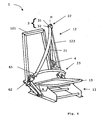
- the upper deflection fitting 7 provides a disc 71 rotatably held in an aperture in the backrest 12.
- the aperture is defined on the illustrated seat structure by the receiving ring 72 for the disc 71.
- the seat belt 21 extends through an elongate through-hole 711 in this disc 71. Due to the rotatable mounting of the disc 71, the elongate through-hole 711 may be suitably aligned with the pulling direction of the seat belt 21.
- the elongate through-hole 711 is preferably designed in the manner of a curved slot.
- the disc 71 may be rotated in the aperture 72, preferably by at least two thirds of a rotation.
Landscapes
- Engineering & Computer Science (AREA)
- Mechanical Engineering (AREA)
- Aviation & Aerospace Engineering (AREA)
- Transportation (AREA)
- Seats For Vehicles (AREA)
- Automotive Seat Belt Assembly (AREA)
Description
- The present invention relates to an end fitting for connecting a seat belt to a reversible seat in a motor vehicle. The present invention further relates to an upper deflection fitting for a reversible seat in a motor vehicle. The present invention further relates to a seat belt arrangement for a reversible seat with a deflection fitting and/or end fitting and a reversible seat with a seat belt arrangement.
- Reversible seats, frequently also denoted as 'reversible vehicle seats', are known. The international patent application
WO 01/70537 A1 - A further mechanism for reversing the seat direction of a passenger on a motor vehicle seat is disclosed in the publication
DE 103 58 719 A1 . The design of a seat facing in two directions and disclosed here, with a backrest part which may be used on both sides and in which the seat surface and the backrest are arranged to be decoupled - from one another, may also be used within the scope of the present invention. - From the generic document
DE 100 34 441 A1 a vehicle seating with a seat base and a backrest, which are adjustable at assigned frame parts opposite the vehicle bodywork, is well-known. Further more the document discloses an articulated end fitting for connecting to a reversible seat with a connecting part and a projecting elongated lug connected thereto for suspending a seat belt.Seats with a backrest which is reversible and/or may be inverted have the advantage that a rotation of the seat about a vertical axis, as was previously provided for reversing the seat direction so that a passenger is able to sit down on the seat either in the direction of travel or opposing the direction of travel, is dispensed with. Such a rotation is disadvantageous, due to the restricted spatial conditions in motor vehicles and due to the anchorage of the seat in the vehicle floor which is frequently weakened by the rotary mechanism. - In contrast to the rotatable seats, the appropriate connection of a seat belt is more complicated with reversible seats. In practice, this has been partially countered by the fact that a seat belt might not be required in the reverse seating position or such a use of the seat might not be allowed during the journey. An adapted seat belt for a reversible seat would, however, be desirable in many cases.
- The object of the present invention, therefore, is to allow an end fitting for a seat belt arrangement on a reversible seat which allows a use of the seat belt in both positions of use. In a further aspect, the object of the present invention is to provide a reversible seat with a seat belt arrangement in which the seat belt may be used in both of the envisaged positions of use.
- In a first aspect, the present invention achieves these objects by a fitting arrangement for a seat belt on a reversible seat with the features according to
Claim 1 and a reversible seat with the features according toClaim 5. - In a second aspect, the object set forth is further achieved by the invention by a reversible seat with an upper deflection fitting, according to the features provided in Claim 8.
- Advantageous embodiments and developments of the present invention are provided in the respective sub-claims.
- The present invention is disclosed by way of example hereinafter, reference being made to the accompanying drawings, in which:
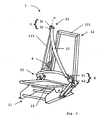
- Figure 1
- is a perspective view of the structure of a reversible seat with a seat belt arrangement according to the present invention in a first position of use;
- Figure 2
- is a perspective view of the reversible seat according to
Figure 1 from a different viewing angle; - Figure 3
- is a perspective view of the reversible seat according to
Figure 1 in a second position of use; - Figure 4
- is a perspective view of the reversible seat according to
Figure 3 from a different viewing angle; - Figure 5
- is a perspective detailed view of the fitting for the lower connecting point of the seat belt to the reversible seat according to
Figure 1 ; - Figure 6
- is a side view of the fitting according to
Figure 5 from the front; - Figure 7
- is a sectional view through the fitting in the plane X-X according to
Figure 6 ; - Figure 8
- is a plan view of the fitting according to
Figure 5 ; and - Figure 9
- is a perspective view of a reversible seat with an alternative embodiment for the upper deflection fitting.
- According to
Figure 1 to Figure 4 , areversible seat 1 for a vehicle and, in particular, for the front passenger seat in a motor vehicle, comprises aseat base 11 with abackrest 12 movably attached thereto. For the sake of clarity, the upholstery placed on the seat structure is not shown. Thereversible seat 1 may be altered between two positions of use by displacing thebackrest 12. Thereversible seat 1 further comprises a seat belt arrangement 2 with aseat belt 21 and a fitting set. The fitting set, in turn, comprises a number offitting elements seat belt 21 to thereversible seat 1. An articulated end fitting 5, a deflection fitting 3, aseat belt buckle 6 and abelt retractor 4 are, in particular, provided. In the variant shown, theseat belt 21 extends away from thebelt retractor 4 inside thebackrest 12, approximately along the centre plane of thebackrest 12 upwardly as far as anupper deflection point 22. Proceeding therefrom, theseat belt 21 crosses the upper body of the passenger and is deflected in the opposingseat belt buckle 6 in an approximately horizontal strand which crosses the lower body of the passenger. The end of theseat belt 21 is held in an articulated end fitting 5. The cooperation of theaforementioned fitting elements reversible seat 1 is disclosed hereinafter in further detail. - In the first position of use of the
reversible seat 1 according toFigure 1 andFigure 2 , thebackrest 12 is located with anupper edge 121 projecting slightly to the left at the left end of theseat surface 13. Thereversible seat 1 may be used with the viewing direction towards the right. In this first position of use, theseat belt 21 according to the illustration has to be guided on the right side in front of thebackrest 12 and along the passenger. - In the second position of use of the
reversible seat 1 according toFigure 3 andFigure 4 , thebackrest 12 is located with anupper edge 121 projecting slightly to the right at the right end of theseat surface 13. Accordingly, thereversible seat 1 may be used with the viewing direction towards the left. In this second position of use, theseat belt 21 according to the illustration has to be guided on the left side in front of thebackrest 12 and along the passenger. - To assist the reversing function disclosed above, all
fitting elements backrest 12 of thereversible seat 1. A special design with regard to the reversing function is not required for thebelt retractor 4 and theseat belt buckle 6. Thebelt retractor 4 is expediently attached to a side edge of thebackrest 12 or in a cavity provided therefor inside thebackrest 12. - In order to allow an alteration to the guidance of the
seat belt 21 when changing between the two disclosed positions of use of thereversible seat 1, specially designedfitting elements upper deflection position 22 and in thelower connecting point 23. Preferably all thesefitting elements backrest 12. Details regarding the construction and mode of operation of thesefitting elements - A
lug 3 with anelongate slot 31 or a D ring is pivotably attached to the top of thebackrest 12 at the side, in theupper deflection position 22 of theseat belt 21. In this connection, the envisaged pivot axis "H" preferably extends in the plane of thebackrest 12 or at a short distance parallel thereto. Particularly preferably, the pivot axis "H" also extends approximately parallel to the side edges of thebackrest 12. In particular in the embodiment shown, it is expedient to align the pivot axis "H" approximately parallel to thelateral tube 123 of the support structure of thebackrest 12. Thedeflection edge 32 defined by theslot 31 in thelug 3 for thebelt 21 may be pivoted about this pivot axis "H" by approximately one full rotation. Thedeflection edge 32 is preferably aligned approximately transversely to the pivot axis "H". - Again according to
Figure 1 to Figure 4 , the lower connectingpoint 23 is arranged on the same side as theupper deflection point 22, laterally on the outside of thebackrest 12. In order to allow a comfortable seat belt fastening position, the lower connectingpoint 23 is preferably also located at a short distance below theseat surface 13 on a downwardly extending part of the seat structure or a specialradial arm 124. Theseat belt 21 is held at the lower connectingpoint 23 by an articulated end fitting 5 with a plurality of pivot axes. The articulated end fitting 5 also comprises, in particular, according toFigure 5 , a connectingpart 51 which is pivotably attached about a first axis "A" on the outer edge of thebackrest 12. Anintermediate part 52 is pivotably held in the connectingpart 51 about a further axis "B". Preferably, the further axis "B" extends approximately perpendicular to the first axis "A". Aflat lug 53 for connecting theseat belt 21 is arranged in theintermediate part 52 of the articulatedend fitting 5. Theflat lug 53 is fully rotatably mounted in theintermediate part 52 about the envisaged pulling direction "C" of theseat belt 21. - For the correct functioning of the articulated end fitting 5 shown, when reversing the
reversible seat 1, the complete rotatability of theflat lug 53 in theintermediate part 52 about the axis "C" is necessary. However, a rotatability with regard to the two further axes "A" and "B" of the articulated end fitting 5 is not required. A pivotability in a range of approximately one half rotation has to be provided about one of the two axes "A" and "B", whereas with regard to the other axis a pivotability about a markedly smaller angle is sufficient. - When reversing the
reversible seat 1, theseat belt buckle 6 has to be opened, i.e. the retainingtongue 61 and latch 62 of theseat belt buckle 6 are separated. The seat belt is then merely held on thereversible seat 1 by the articulated end fitting 5, the deflection fitting 3 and thebelt retractor 4. When tilting thebackrest 12, the user wraps the free part of the seat belt with the retainingtongue 61 around the outside of thebackrest 12. The deflection fitting 3 is therefore slightly pivoted about the axis "H". The articulated end fitting 5 adopts the new pulling direction of theseat belt 21 by a pivoting movement about one of the axes "A" or "B". As a result of the wrapping of theseat belt 21, said seat belt is twisted into itself. By a rotation of theflat lug 53 about the pulling direction of theseat belt 21, i.e. the axis "C", this twisting is easily remedied by the user. - Naturally, as an alternative to the disclosed embodiment of the articulated end fitting 5 in the manner of a universal joint, double joint or double axis joint with a further inner axis of rotation "C" in the pulling direction of the
seat belt 21, a ball joint may also be used to connect theseat belt 21. - Furthermore, as an alternative to the position shown and previously disclosed in
Figure 1 to Figure 4 , thebelt retractor 4 may also be arranged inside thebackrest 12 on its side edge in the region between theupper deflection point 22 and the lower connectingpoint 23. - Departing from the arrangement shown in
Figure 1 to Figure 4 , the deflection fitting 3 may also be pivotably attached to theupper deflection point 22 about a horizontal axis approximately parallel to the centre plane of the backrest. In this connection, however, a sufficient height of thebackrest 12 is required in order to achieve guidance of the belt which is reliable and as straight as possible over the shoulder of the passenger. - An alternative design for the upper deflection fitting is shown and illustrated in
Figure 9 . The upper deflection fitting 7, shown here, provides adisc 71 rotatably held in an aperture in thebackrest 12. The aperture is defined on the illustrated seat structure by the receivingring 72 for thedisc 71. In this connection, theseat belt 21 extends through an elongate through-hole 711 in thisdisc 71. Due to the rotatable mounting of thedisc 71, the elongate through-hole 711 may be suitably aligned with the pulling direction of theseat belt 21. The elongate through-hole 711 is preferably designed in the manner of a curved slot. Thedisc 71 may be rotated in theaperture 72, preferably by at least two thirds of a rotation. -
Reversible seat 1 Seat base 11 Backrest 12 Upper edge 121 Support structure, lateral tube 123 Radial arm 124 Seat surface 13 Seat belt arrangement 2 Seat belt 21 Upper deflection point 22 Lower connecting point 23 Lug 3 Slot 31 Deflection edge 32 Belt retractor 4 Articulated end fitting 5 Connecting part 51 Intermediate part 52 Flat lug 53 Seat belt buckle 6 Retaining tongue 61 Latch 62 Alternative upper deflection fitting 7 Disc 71 Through- hole 711 Receiving ring 72
Claims (11)
- Articulated end fitting (5) for connecting a seat belt (21) to a reversible seat (1) with a connecting part (51) and a projecting elongate lug (53) connected thereto for suspending a seat belt (21), characterized in, that the elongate lug (53) being rotatable about an axis (C) extending approximately in the pulling direction of the seat belt (21).
- Articulated end fitting (5) according to Claim 1, whereas the elongate lug (53) being pivotable relative to the connecting part (51) about two further variable axes (A, B).
- Articulated end fitting (5) according to Claim 1 or 2, whereas the elongate lug (53) of the connecting part (5) being fully rotatable about the envisaged pulling direction of the seat belt (21).
- Articulated end fitting (5) according to Claim 1, whereas the fastening point (51) and the elongate lug (53) being connected by a ball joint on the first fitting element (5).
- Articulated end fitting (5) according to one of Claims 1 to 3, whereas on the first fitting element (5) the fastening point (51) and the elongate lug (53) being connected by a universal joint, double or double axis joint, in which the elongate lug (53) is further pivotably movably held or rotatably movably held about the envisaged pulling direction of the seat belt (21).
- Reversible seat (1) for a vehicle with an articulated end fitting (5) according to one of Claims 1 to 5, whereas the articulated end fitting (5) being arranged in the region of the lower end (23) of the backrest (12) or on a holder located thereunder, in particular on a radial arm (124) projecting downwardly.
- Reversible seat (1) for a motor vehicle according to Claim 6, with a second fitting element (3) which is arranged on the side of the first fitting element (5) in the region of the upper end (121) of the backrest (12) and defines a deflection edge (32) for the seat belt (21), the deflection edge (32) being pivotable about an axis (C) located approximately in the plane of the backrest (12).
- Reversible seat (1) for a motor vehicle according to Claim 6 or 7, whereas all fitting elements (3, 4, 5, 6) for the seat belt (21) being established relative to the movable backrest (12).
- Reversible seat (1) for a motor vehicle with an upper deflection fitting (7) arranged on the backrest (12) for a seat belt (21) and a belt retractor (4) arranged in a space within the backrest (12), whereas the upper deflection fitting (7) comprising a disc (71) rotatably held in an aperture in the backrest (12) with an elongate through-hole (711) for the emergence of the seat belt (21) from the backrest (12).
- Reversible seat according to Claim 9, whereas the elongate through-hole (711) being configured as a curved slot.
- Reversible seat according to Claim 9 or 10, whereas the aperture in the backrest being established by a receiving ring (72).
Applications Claiming Priority (2)
| Application Number | Priority Date | Filing Date | Title |
|---|---|---|---|
| DE102005061541A DE102005061541B4 (en) | 2005-12-22 | 2005-12-22 | Safety belt fitting for a reversible seat |
| PCT/EP2006/012388 WO2007071418A1 (en) | 2005-12-22 | 2006-12-21 | Seat belt fitting for a reversible seat |
Publications (2)
| Publication Number | Publication Date |
|---|---|
| EP1963131A1 EP1963131A1 (en) | 2008-09-03 |
| EP1963131B1 true EP1963131B1 (en) | 2009-07-22 |
Family
ID=37897350
Family Applications (1)
| Application Number | Title | Priority Date | Filing Date |
|---|---|---|---|
| EP06829820A Not-in-force EP1963131B1 (en) | 2005-12-22 | 2006-12-21 | Seat belt fitting for a reversible seat |
Country Status (4)
| Country | Link |
|---|---|
| US (1) | US7954902B2 (en) |
| EP (1) | EP1963131B1 (en) |
| DE (2) | DE102005061541B4 (en) |
| WO (1) | WO2007071418A1 (en) |
Families Citing this family (10)
| Publication number | Priority date | Publication date | Assignee | Title |
|---|---|---|---|---|
| WO2009131551A1 (en) * | 2008-04-22 | 2009-10-29 | Mhd Samer Aldardary | Mechanism for passengers safety at sudden deceleration and acceleration trauma |
| US9707421B2 (en) | 2013-02-08 | 2017-07-18 | D B Industries, Llc | Energy absorber cover |
| US9150178B1 (en) | 2014-03-11 | 2015-10-06 | Ford Global Technologies, Llc | Seatbelt restraint system for reversible vehicle seat |
| US9376089B1 (en) | 2015-03-24 | 2016-06-28 | GM Global Technology Operations LLC | Hinged seatbelt connection |
| US10005422B2 (en) * | 2015-08-12 | 2018-06-26 | Kevin Gallagher | Side seat and swivel restraint system |
| KR101782415B1 (en) | 2016-09-02 | 2017-09-28 | 현대자동차주식회사 | Belt anchor unit and safety belt assembly having the same |
| JP7771856B2 (en) * | 2022-04-21 | 2025-11-18 | 豊田合成株式会社 | Occupant protection devices |
| DE102022002516B4 (en) | 2022-07-11 | 2025-04-24 | Mercedes-Benz Group AG | Belt arrangement for a vehicle |
| DE102022132183B4 (en) * | 2022-12-05 | 2025-12-04 | Autoliv Development Ab | Seatbelt retractor and vehicle seat |
| KR102842687B1 (en) * | 2023-07-28 | 2025-08-06 | 아우토리브 디벨롭먼트 아베 | Seat belt retractor for biderection seat |
Family Cites Families (30)
| Publication number | Priority date | Publication date | Assignee | Title |
|---|---|---|---|---|
| US3080634A (en) * | 1959-09-29 | 1963-03-12 | Lindblad Stig Martin | Attachments for automobile safety belts |
| US3691788A (en) * | 1970-09-10 | 1972-09-19 | Ralph Mazziotti | Stay-rite flex joint |
| SE7500247L (en) * | 1975-01-10 | 1976-07-12 | Lindblad O L | DELIVERY DEVICE FOR SEAT BELTS |
| US4306735A (en) * | 1976-11-30 | 1981-12-22 | Allied Chemical Corporation | Safety belt clamp apparatus, occupant restraint system and method |
| US4191400A (en) * | 1977-03-25 | 1980-03-04 | Repa Feinstanzwerk Gmbh | Swiveling anchor for occupant restraint system |
| US4159848A (en) * | 1978-06-12 | 1979-07-03 | General Motors Corporation | Linear locking seat belt retractor |
| JPS55123543A (en) * | 1979-03-17 | 1980-09-24 | Takata Kk | Belt guide with belt stopper |
| US4431330A (en) * | 1982-04-12 | 1984-02-14 | Tuthill Corporation | Ball joint improvement and method |
| DE3306095A1 (en) * | 1983-02-22 | 1984-08-30 | Repa Feinstanzwerk Gmbh, 7071 Alfdorf | DEVICE FITTING FOR SAFETY BELTS IN MOTOR VEHICLES |
| US4549769A (en) * | 1984-07-20 | 1985-10-29 | General Motors Corporation | Belt clamping guide loop |
| US4648625A (en) * | 1985-06-28 | 1987-03-10 | Lynch James P B | Seat belt tension relief device |
| DE3530495A1 (en) * | 1985-08-27 | 1987-03-05 | Porsche Ag | SAFETY BELT, ESPECIALLY 3-POINT SAFETY BELT FOR VEHICLES, AIRPLANES OR THE LIKE |
| GB8619161D0 (en) * | 1986-08-06 | 1986-09-17 | Britax Ltd | Clamping strap |
| DE3715861A1 (en) | 1987-05-12 | 1988-12-01 | Ase Deutschland Gmbh | Device for tightening a safety belt |
| US5556171A (en) * | 1995-02-21 | 1996-09-17 | Trw Vehicle Safety Systems Inc. | Seat belt bezel assembly |
| US5544917A (en) * | 1995-07-13 | 1996-08-13 | Trw Vehicle Safety Systems Inc. | Seat belt webbing guide assembly |
| US5609396A (en) * | 1995-07-26 | 1997-03-11 | Trw Vehicle Safety Systems Inc. | Apparatus for restraining a vehicle occupant |
| US5730499A (en) * | 1995-09-29 | 1998-03-24 | Ford Global Technologies, Inc. | Adjustable guide assembly for a vehicle seat belt system |
| US5599070A (en) | 1995-12-12 | 1997-02-04 | Trw Vehicle Safety Systems Inc. | Seat and integral seat belt |
| US5658051A (en) * | 1995-12-28 | 1997-08-19 | Alliedsignal Inc. | Gimbaled web guide for a seat-integrated-belt restraint system |
| US5722732A (en) * | 1996-08-26 | 1998-03-03 | General Motors Corporation | Shoulder belt retractor with headrest support |
| US5964505A (en) * | 1996-09-24 | 1999-10-12 | Lear Corp. | Detachable cantilevered headrest having a ratchet mechanism |
| US5988758A (en) * | 1997-05-13 | 1999-11-23 | Breed Automotive Technology, Inc. | Seat belt retractor exit cover with integral escutcheon |
| JP4263409B2 (en) * | 2000-03-22 | 2009-05-13 | マグナ シーティング システムズ インコーポレイテッド | Multi-positionable and reversible seat assembly |
| DE10034441A1 (en) * | 2000-07-15 | 2002-01-24 | Bayerische Motoren Werke Ag | Automobile seat assembly has a rigid L-shaped frame to hold the seat and backrest frame sections with easy adjustments to position and alignment according to the stature of the occupant |
| DE10056127A1 (en) * | 2000-11-13 | 2002-05-23 | Magna Seating Systems Gmbh | Mounting for car safety belt comprises two chain links with gap between them which act as belt guide and are mounted on pivot consisting of bolt in sleeve passing through them |
| US6520588B1 (en) * | 2000-11-16 | 2003-02-18 | Trw Vehicle Safety Systems Inc. | Seat belt guide |
| GB2398547A (en) * | 2003-02-24 | 2004-08-25 | Autoliv Dev | Seat belt retractor with rotatable guide member |
| DE10358719A1 (en) * | 2003-12-10 | 2005-07-14 | Volkswagen Ag | Motor vehicle e.g. minibus, seat, has back rest and seat`s base part that are not attached to each other, where base part is moved by gimbal moving arrangement and rest is displaced around swiveling axes |
| DE102005004954B4 (en) * | 2004-04-06 | 2008-01-03 | Daimlerchrysler Ag | deflecting |
-
2005
- 2005-12-22 DE DE102005061541A patent/DE102005061541B4/en not_active Expired - Fee Related
-
2006
- 2006-12-21 US US12/158,751 patent/US7954902B2/en not_active Expired - Fee Related
- 2006-12-21 WO PCT/EP2006/012388 patent/WO2007071418A1/en not_active Ceased
- 2006-12-21 EP EP06829820A patent/EP1963131B1/en not_active Not-in-force
- 2006-12-21 DE DE602006008037T patent/DE602006008037D1/en active Active
Also Published As
| Publication number | Publication date |
|---|---|
| DE102005061541A1 (en) | 2007-07-05 |
| DE102005061541B4 (en) | 2009-08-27 |
| US7954902B2 (en) | 2011-06-07 |
| DE602006008037D1 (en) | 2009-09-03 |
| WO2007071418A1 (en) | 2007-06-28 |
| EP1963131A1 (en) | 2008-09-03 |
| US20080265643A1 (en) | 2008-10-30 |
Similar Documents
| Publication | Publication Date | Title |
|---|---|---|
| US10239419B2 (en) | Anthropomorphic pivotable upper seatback support | |
| US9126508B2 (en) | Upper seatback pivot system | |
| US9776533B2 (en) | Torsion bar upper seatback support assembly | |
| US9126504B2 (en) | Integrated thin flex composite headrest assembly | |
| EP2923897B1 (en) | Vehicle seat | |
| US9333882B2 (en) | Manual upper seatback support | |
| US9315130B2 (en) | Articulating head restraint | |
| US20060255635A1 (en) | Vehicle seat | |
| US9114880B2 (en) | Aircraft seat back with improved comfort and reduced size | |
| US20170253153A1 (en) | Multi-adjustable head restraint | |
| US7954902B2 (en) | Seat belt fitting for a reversible seat | |
| JP2017039468A (en) | Vehicle seat and vehicle | |
| WO2007026790A1 (en) | Vehicle seat and method of assembling vehicle seat | |
| US20190184878A1 (en) | Vehicle seat with cantilevered headrest assembly and positioning system | |
| US7237842B2 (en) | Headrest, particularly for a motor vehicle seat | |
| CN104228618A (en) | Vehicle seat | |
| US9145071B2 (en) | Vehicle seat, in particular motor vehicle seat | |
| CN106183903B (en) | Device for reclining the rear seats of a vehicle | |
| US20130069405A1 (en) | Vehicle seat | |
| US6533341B2 (en) | Adjustable pivoting means for a vehicle seat backrest | |
| US20090102264A1 (en) | Vehicle Seat | |
| JPH0366882B2 (en) | ||
| US20180015854A1 (en) | Seat structure for vehicle | |
| EP0999093B1 (en) | Headrest assembly for vehicle seats | |
| US8616614B2 (en) | Armrest structure for vehicle and setting method of armrest height for vehicle |
Legal Events
| Date | Code | Title | Description |
|---|---|---|---|
| PUAI | Public reference made under article 153(3) epc to a published international application that has entered the european phase |
Free format text: ORIGINAL CODE: 0009012 |
|
| 17P | Request for examination filed |
Effective date: 20080707 |
|
| AK | Designated contracting states |
Kind code of ref document: A1 Designated state(s): AT BE BG CH CY CZ DE DK EE ES FI FR GB GR HU IE IS IT LI LT LU LV MC NL PL PT RO SE SI SK TR |
|
| 17Q | First examination report despatched |
Effective date: 20081023 |
|
| GRAP | Despatch of communication of intention to grant a patent |
Free format text: ORIGINAL CODE: EPIDOSNIGR1 |
|
| RAP1 | Party data changed (applicant data changed or rights of an application transferred) |
Owner name: MAGNA SEATING (GERMANY) GMBH |
|
| GRAS | Grant fee paid |
Free format text: ORIGINAL CODE: EPIDOSNIGR3 |
|
| GRAA | (expected) grant |
Free format text: ORIGINAL CODE: 0009210 |
|
| AK | Designated contracting states |
Kind code of ref document: B1 Designated state(s): AT BE BG CH CY CZ DE DK EE ES FI FR GB GR HU IE IS IT LI LT LU LV MC NL PL PT RO SE SI SK TR |
|
| REG | Reference to a national code |
Ref country code: GB Ref legal event code: FG4D |
|
| REG | Reference to a national code |
Ref country code: CH Ref legal event code: EP |
|
| REG | Reference to a national code |
Ref country code: IE Ref legal event code: FG4D |
|
| REF | Corresponds to: |
Ref document number: 602006008037 Country of ref document: DE Date of ref document: 20090903 Kind code of ref document: P |
|
| NLV1 | Nl: lapsed or annulled due to failure to fulfill the requirements of art. 29p and 29m of the patents act | ||
| PG25 | Lapsed in a contracting state [announced via postgrant information from national office to epo] |
Ref country code: FI Free format text: LAPSE BECAUSE OF FAILURE TO SUBMIT A TRANSLATION OF THE DESCRIPTION OR TO PAY THE FEE WITHIN THE PRESCRIBED TIME-LIMIT Effective date: 20090722 Ref country code: ES Free format text: LAPSE BECAUSE OF FAILURE TO SUBMIT A TRANSLATION OF THE DESCRIPTION OR TO PAY THE FEE WITHIN THE PRESCRIBED TIME-LIMIT Effective date: 20091102 Ref country code: SE Free format text: LAPSE BECAUSE OF FAILURE TO SUBMIT A TRANSLATION OF THE DESCRIPTION OR TO PAY THE FEE WITHIN THE PRESCRIBED TIME-LIMIT Effective date: 20090722 Ref country code: LT Free format text: LAPSE BECAUSE OF FAILURE TO SUBMIT A TRANSLATION OF THE DESCRIPTION OR TO PAY THE FEE WITHIN THE PRESCRIBED TIME-LIMIT Effective date: 20090722 Ref country code: IS Free format text: LAPSE BECAUSE OF FAILURE TO SUBMIT A TRANSLATION OF THE DESCRIPTION OR TO PAY THE FEE WITHIN THE PRESCRIBED TIME-LIMIT Effective date: 20091122 Ref country code: AT Free format text: LAPSE BECAUSE OF FAILURE TO SUBMIT A TRANSLATION OF THE DESCRIPTION OR TO PAY THE FEE WITHIN THE PRESCRIBED TIME-LIMIT Effective date: 20090722 |
|
| PG25 | Lapsed in a contracting state [announced via postgrant information from national office to epo] |
Ref country code: LV Free format text: LAPSE BECAUSE OF FAILURE TO SUBMIT A TRANSLATION OF THE DESCRIPTION OR TO PAY THE FEE WITHIN THE PRESCRIBED TIME-LIMIT Effective date: 20090722 Ref country code: SI Free format text: LAPSE BECAUSE OF FAILURE TO SUBMIT A TRANSLATION OF THE DESCRIPTION OR TO PAY THE FEE WITHIN THE PRESCRIBED TIME-LIMIT Effective date: 20090722 Ref country code: NL Free format text: LAPSE BECAUSE OF FAILURE TO SUBMIT A TRANSLATION OF THE DESCRIPTION OR TO PAY THE FEE WITHIN THE PRESCRIBED TIME-LIMIT Effective date: 20090722 Ref country code: PL Free format text: LAPSE BECAUSE OF FAILURE TO SUBMIT A TRANSLATION OF THE DESCRIPTION OR TO PAY THE FEE WITHIN THE PRESCRIBED TIME-LIMIT Effective date: 20090722 |
|
| PG25 | Lapsed in a contracting state [announced via postgrant information from national office to epo] |
Ref country code: BG Free format text: LAPSE BECAUSE OF FAILURE TO SUBMIT A TRANSLATION OF THE DESCRIPTION OR TO PAY THE FEE WITHIN THE PRESCRIBED TIME-LIMIT Effective date: 20091022 Ref country code: PT Free format text: LAPSE BECAUSE OF FAILURE TO SUBMIT A TRANSLATION OF THE DESCRIPTION OR TO PAY THE FEE WITHIN THE PRESCRIBED TIME-LIMIT Effective date: 20091122 |
|
| PG25 | Lapsed in a contracting state [announced via postgrant information from national office to epo] |
Ref country code: CZ Free format text: LAPSE BECAUSE OF FAILURE TO SUBMIT A TRANSLATION OF THE DESCRIPTION OR TO PAY THE FEE WITHIN THE PRESCRIBED TIME-LIMIT Effective date: 20090722 Ref country code: DK Free format text: LAPSE BECAUSE OF FAILURE TO SUBMIT A TRANSLATION OF THE DESCRIPTION OR TO PAY THE FEE WITHIN THE PRESCRIBED TIME-LIMIT Effective date: 20090722 Ref country code: EE Free format text: LAPSE BECAUSE OF FAILURE TO SUBMIT A TRANSLATION OF THE DESCRIPTION OR TO PAY THE FEE WITHIN THE PRESCRIBED TIME-LIMIT Effective date: 20090722 Ref country code: RO Free format text: LAPSE BECAUSE OF FAILURE TO SUBMIT A TRANSLATION OF THE DESCRIPTION OR TO PAY THE FEE WITHIN THE PRESCRIBED TIME-LIMIT Effective date: 20090722 |
|
| PLBE | No opposition filed within time limit |
Free format text: ORIGINAL CODE: 0009261 |
|
| STAA | Information on the status of an ep patent application or granted ep patent |
Free format text: STATUS: NO OPPOSITION FILED WITHIN TIME LIMIT |
|
| PG25 | Lapsed in a contracting state [announced via postgrant information from national office to epo] |
Ref country code: BE Free format text: LAPSE BECAUSE OF FAILURE TO SUBMIT A TRANSLATION OF THE DESCRIPTION OR TO PAY THE FEE WITHIN THE PRESCRIBED TIME-LIMIT Effective date: 20090722 Ref country code: SK Free format text: LAPSE BECAUSE OF FAILURE TO SUBMIT A TRANSLATION OF THE DESCRIPTION OR TO PAY THE FEE WITHIN THE PRESCRIBED TIME-LIMIT Effective date: 20090722 |
|
| 26N | No opposition filed |
Effective date: 20100423 |
|
| PG25 | Lapsed in a contracting state [announced via postgrant information from national office to epo] |
Ref country code: MC Free format text: LAPSE BECAUSE OF NON-PAYMENT OF DUE FEES Effective date: 20100701 |
|
| PG25 | Lapsed in a contracting state [announced via postgrant information from national office to epo] |
Ref country code: IE Free format text: LAPSE BECAUSE OF NON-PAYMENT OF DUE FEES Effective date: 20091221 Ref country code: GR Free format text: LAPSE BECAUSE OF FAILURE TO SUBMIT A TRANSLATION OF THE DESCRIPTION OR TO PAY THE FEE WITHIN THE PRESCRIBED TIME-LIMIT Effective date: 20091023 |
|
| PG25 | Lapsed in a contracting state [announced via postgrant information from national office to epo] |
Ref country code: IT Free format text: LAPSE BECAUSE OF FAILURE TO SUBMIT A TRANSLATION OF THE DESCRIPTION OR TO PAY THE FEE WITHIN THE PRESCRIBED TIME-LIMIT Effective date: 20090722 |
|
| PG25 | Lapsed in a contracting state [announced via postgrant information from national office to epo] |
Ref country code: LU Free format text: LAPSE BECAUSE OF NON-PAYMENT OF DUE FEES Effective date: 20091221 |
|
| PG25 | Lapsed in a contracting state [announced via postgrant information from national office to epo] |
Ref country code: HU Free format text: LAPSE BECAUSE OF FAILURE TO SUBMIT A TRANSLATION OF THE DESCRIPTION OR TO PAY THE FEE WITHIN THE PRESCRIBED TIME-LIMIT Effective date: 20100123 |
|
| REG | Reference to a national code |
Ref country code: CH Ref legal event code: PL |
|
| PG25 | Lapsed in a contracting state [announced via postgrant information from national office to epo] |
Ref country code: TR Free format text: LAPSE BECAUSE OF FAILURE TO SUBMIT A TRANSLATION OF THE DESCRIPTION OR TO PAY THE FEE WITHIN THE PRESCRIBED TIME-LIMIT Effective date: 20090722 |
|
| PG25 | Lapsed in a contracting state [announced via postgrant information from national office to epo] |
Ref country code: CY Free format text: LAPSE BECAUSE OF FAILURE TO SUBMIT A TRANSLATION OF THE DESCRIPTION OR TO PAY THE FEE WITHIN THE PRESCRIBED TIME-LIMIT Effective date: 20090722 |
|
| PG25 | Lapsed in a contracting state [announced via postgrant information from national office to epo] |
Ref country code: LI Free format text: LAPSE BECAUSE OF NON-PAYMENT OF DUE FEES Effective date: 20101231 Ref country code: CH Free format text: LAPSE BECAUSE OF NON-PAYMENT OF DUE FEES Effective date: 20101231 |
|
| PGFP | Annual fee paid to national office [announced via postgrant information from national office to epo] |
Ref country code: GB Payment date: 20121220 Year of fee payment: 7 |
|
| GBPC | Gb: european patent ceased through non-payment of renewal fee |
Effective date: 20131221 |
|
| PG25 | Lapsed in a contracting state [announced via postgrant information from national office to epo] |
Ref country code: GB Free format text: LAPSE BECAUSE OF NON-PAYMENT OF DUE FEES Effective date: 20131221 |
|
| PGFP | Annual fee paid to national office [announced via postgrant information from national office to epo] |
Ref country code: FR Payment date: 20141219 Year of fee payment: 9 |
|
| REG | Reference to a national code |
Ref country code: FR Ref legal event code: ST Effective date: 20160831 |
|
| PG25 | Lapsed in a contracting state [announced via postgrant information from national office to epo] |
Ref country code: FR Free format text: LAPSE BECAUSE OF NON-PAYMENT OF DUE FEES Effective date: 20151231 |
|
| PGFP | Annual fee paid to national office [announced via postgrant information from national office to epo] |
Ref country code: DE Payment date: 20231214 Year of fee payment: 18 |
|
| REG | Reference to a national code |
Ref country code: DE Ref legal event code: R119 Ref document number: 602006008037 Country of ref document: DE |
|
| PG25 | Lapsed in a contracting state [announced via postgrant information from national office to epo] |
Ref country code: DE Free format text: LAPSE BECAUSE OF NON-PAYMENT OF DUE FEES Effective date: 20250701 |