EP1962459A2 - Datenkommunikationssystem und Sitzungsverwaltungsserver - Google Patents
Datenkommunikationssystem und Sitzungsverwaltungsserver Download PDFInfo
- Publication number
- EP1962459A2 EP1962459A2 EP20080003203 EP08003203A EP1962459A2 EP 1962459 A2 EP1962459 A2 EP 1962459A2 EP 20080003203 EP20080003203 EP 20080003203 EP 08003203 A EP08003203 A EP 08003203A EP 1962459 A2 EP1962459 A2 EP 1962459A2
- Authority
- EP
- European Patent Office
- Prior art keywords
- communication device
- communication
- message
- session management
- sip
- Prior art date
- Legal status (The legal status is an assumption and is not a legal conclusion. Google has not performed a legal analysis and makes no representation as to the accuracy of the status listed.)
- Withdrawn
Links
Images


Classifications
-
- H—ELECTRICITY
- H04—ELECTRIC COMMUNICATION TECHNIQUE
- H04L—TRANSMISSION OF DIGITAL INFORMATION, e.g. TELEGRAPHIC COMMUNICATION
- H04L65/00—Network arrangements, protocols or services for supporting real-time applications in data packet communication
- H04L65/10—Architectures or entities
- H04L65/1046—Call controllers; Call servers
-
- H—ELECTRICITY
- H04—ELECTRIC COMMUNICATION TECHNIQUE
- H04L—TRANSMISSION OF DIGITAL INFORMATION, e.g. TELEGRAPHIC COMMUNICATION
- H04L67/00—Network arrangements or protocols for supporting network services or applications
- H04L67/01—Protocols
- H04L67/10—Protocols in which an application is distributed across nodes in the network
- H04L67/1001—Protocols in which an application is distributed across nodes in the network for accessing one among a plurality of replicated servers
- H04L67/1027—Persistence of sessions during load balancing
-
- H—ELECTRICITY
- H04—ELECTRIC COMMUNICATION TECHNIQUE
- H04L—TRANSMISSION OF DIGITAL INFORMATION, e.g. TELEGRAPHIC COMMUNICATION
- H04L67/00—Network arrangements or protocols for supporting network services or applications
- H04L67/14—Session management
Definitions
- the present invention relates to a data communication method and system. More particularly, it relates to a data communication method and system that enable data communication between communication devices by using a session management server apparatus.
- a communication control protocol is often used, which is independent of the data communication, in order to exercise control over the data communication, such as enabling the data communication or shutting down the data communication.
- SIP Session Initiation Protocol
- IETF IETF, RFC 3261: SIP: Session Initiation Protocol, ⁇ URL: http://www.ietf.org/rfc/rfc3261.txt> (hereinafter referred to as Patent Document 1").
- a communication session (hereinafter, simply referred to as "session") is established between a first communication device and a second communication device, by using a session management server, thereby enabling the data communication in the SIP.
- the first communication device registers an IP address of the communication device in the session management server.
- the communication device transmits to the session management server, a registration request message (also referred to as "REGISTER message") including an identifier (also referred to as "SIP-URI”) for uniquely specifying the communication device or a user thereof in the session management server, and an IP address of the communication device.
- REGISTER message also referred to as "REGISTER message”
- SIP-URI identifier
- IP-URI IP address of the communication device.
- the session management server records the identifier and the IP address described in the registration request message, such that the identifier and the IP address are associated with each other.
- the configuration is such that an association between the identifier and the IP address of a certain communication device, being recorded in the session management server, is deleted after a lapse of an effective period that is set when the association is recorded.
- the association can be deleted by sending, from the communication device, a registration deletion request message (for example, a directive setting zero as the effective period of the association is included in the aforementioned REGISTER message).
- the communication device being logged into the session management server a state where the identifier and the IP address of a communication device (entity), being associated with each other, are recorded in the session management server.
- the communication device being logged out of the session management server the state where these elements are not recorded.
- This login action enables a transmission of an INVITE message (described below), which the session management server has received from a source communication device, to a destination communication device.
- the session management server becomes available for accepting the INVITE message or the like from the destination device.
- the second communication device prior to the session establishment, the second communication device also is logged into the session management server.
- the first communication device transmits, to the session management server, a session establishment request (hereinafter, also referred to as "INVITE message"), which requests establishment of a session between the first communication device and the second communication device.
- INVITE message a session establishment request
- An identifier of the first communication device and an identifier of the second communication device are described in the INVITE message.
- the session management server which has received the INVITE message transmits this INVITE message to the second communication device.
- the second communication device which received the INVITE message accepts the session establishment request
- the second communication device transmits, to the session management server, a response message (also referred to as "200 OK message" representing the acceptance.
- the session management server returns the response message to the first communication device.
- the communication session between the first communication device and the second communication device is established.
- the session management server Upon receipt of a message from a communication device, the session management server processes the message, while appropriately updating information indicating which communication device currently is logged in, and a communication state between any of the communication devices.
- the state of the communication is also referred to as "call state”, representing “calling”, “established”, “shutting down communication”, or the like. Therefore, as the number of the communication devices that are logged into the session management server increases, the load on the session management server becomes heavier.
- the second session management server transfers the INVITE message to the second communication device.
- the second communication device transmits a response message to the second session management server.
- the second session management server which received the response message transfers the response message to the first session management server.
- the first session management server transfers the response message to the first communication device.
- the SIP-URI of the communication device includes information indicating which session management server manages the communication device.
- the SIP-URI is "USERI@SIPSERVER1.HITACHI.COM”
- "SIPSERVER1.HITACHI.COM” indicates information for identifying the session management server (usually, it is referred to as a "domain").
- the session management server manages a table in which the server's own IP address and identification information of a linked session management server are associated with each other, and decides a session management server to which a message is transmitted.
- Patent Document 2 discloses a method that stores a call state in a database that is readable and writable from the multiple session management servers, and an available server among the multiple servers performs processing.
- Patent Document 1 states that an encrypted communication protocol such as TLS and S/MINE is employed in order to prevent tapping and/or tampering of communication data between the session management server and the communication device.
- an encrypted communication protocol such as TLS and S/MINE is employed in order to prevent tapping and/or tampering of communication data between the session management server and the communication device.
- the load balancer dynamically chooses a session management server for processing and distributing the message, and therefore, the problem as' described above is not present.
- holding the communication session indicates, for example, sharing of state information indicating to what extent data has been transmitted or received, in both of the data transmitting source and the data receiving end. Therefore, the problem above may occur not only in the TLS, but also in a connection-type communication typified by TCP, which performs communication and also checking whether the data has reached the destination, even while the data is being communicated.
- the present invention provides a data communication system which allows load balancing of session management servers without incorporating identification information of the session management server into identification information of a communication device.
- the present invention provides a data communication system which allows a flexible increase and decrease in the number of session management servers.
- the present invention provides a data communication system which enables implementation of data communication while distributing a message-processing load applied on the session management servers, even when communication which needs common information is performed between the session management server and the communication device.
- the present invention is primarily directed to a data communication system including multiple communication devices which perform data communication mutually, multiple session management servers which manage a session of data communication between the communication devices, and a load balancer which assigns any of the session management servers according to a predetermined criterion for processing a message received from any of the communication devices, wherein, the session management servers are provided with, a unit for managing a currently logged-in communication device and a state of the communication performed by the login communication device, and a unit for acquiring information necessary for communicating with any of the communication devices.
- the information necessary for communicating with the communication device corresponds to information relating to the session management server that manages the communication device, and common information for holding a communication session with the communication device.
- the data communication system provided by the present invention includes multiple session management servers which manage a session of the data communication between the communication devices, a load balancer which assigns, to any of the session management servers according to a predetermined criterion, a communication message from a first communication device to a second communication device, the message not being provided with information for identifying the session management server that manages the second communication device, and a unit which causes the session management server that received the communication message from the load balancer to acquire information necessary for communicating with the second communication device.
- the information necessary for communicating with the second communication device may be identification information for specifying the session management server to which the second communication device is logged in.
- the unit which causes the session management server to acquire information necessary for communicating with the second communication device may include, an inquiring unit in which the session management server that received the message of session establishment request inquires other session management server whether or not the second communication device is logged in, and a responding unit, in which a session management server to which the second communication device is logged in, makes a response, indicating that the second communication device is logged in thereto, to the session management server that received the message of session establishment request.
- the unit which causes the session management server to acquire information necessary for communicating with the second communication device may further include a shared database which is accessible to the multiple session management servers, and which records identification information for identifying the session management server to which the communication device is logged in, and a searching unit in which the session management server that has received the message of session establishment request searches the shared database.
- the communication message may be a session establishment request message or a session establishment response message.
- the information necessary for communicating with the second communication device may be an encrypted communication setting used for communicating with the second communication device
- the unit which causes the session management device to acquire information for communicating with the second communication device may include a shared database which is accessible to the multiple session management servers, for recording the encrypted communication setting used for communicating with the second communication device, and a searching unit in which the session management server that received the session establishment request message searches the shared database.
- the communication message may be a call information search request message or a call information search response message.
- the identification information for specifying the session management server may be a domain name, a host name, an IP address, a URI, or the like.
- the session management server to which the communication device is logged into is selected by the load balancer when the communication device transmits a REGISTER message. Therefore, in the SIP-URI domain of the communication device, parent organization information can be described instead of the identification information of the session management server, and simultaneously enabling an operation to increase or decrease the number of the session management servers, according to the number of communication devices.
- the session management server acquires information necessary for communicating with the communication device being a message-sending destination, and transmits the message. Therefore, even when the communication is performed, which requires common information between the session management server and the communication device, data communication can be implemented while distributing the message-processing load that is applied on the session management server.
- a load balancing method is possible which satisfies both reliable communication and secure communication.
- the present invention can be applied to a system for transmitting and receiving a session establishment request message and a response message, via the session management server, when a communication session is established.
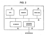
- the following embodiments incorporate devices as illustrated by the configuration example in FIG. 2 : for instance, a processor (CPU) 91, a memory 92 and/or a hard disk 93 for storing various software (programs) executed by the processor 91 and data, a network interface 94 for coupling with network 0 (LAN 1, LAN 2), and an I/O device 95 including an input device such as a mouse and a keyboard, a display device, and a reader/writer for reading to and writing from an external storage medium, and each of the devices is implemented in a general electronic computer where the elements above are mutually coupled via internal communication lines (referred to as "bus") 16.
- a processor CPU
- memory 92 for instance, a memory 92 and/or a hard disk 93 for storing various software (programs) executed by the processor 91 and data
- a network interface 94 for coupling with network 0 (LAN 1, LAN 2)
- an I/O device 95 including an input device such as a mouse and a keyboard, a display device,
- a processing unit provided in each device and its processing stage in each of the following embodiments are implemented, with the processor 91 executing necessary programs stored in the hard disk 93 or in the memory 92 at a necessary timing in each of the devices.
- These programs may be stored in advance in the hard disk 93 or in the memory 92 within each device.
- these programs may be introduced from another device, when needed, into the storage above via a medium available for the device.
- the medium may represent, for example, a detachable storage medium available in the I/O device 95, or a communication medium available via the network interface 94 (i.e., a network, or a carrier wave or a digital signal propagating through the network). It is further possible to configure each processing unit described above as hardware such as an integrated circuit.
- identifiers such as domain name, URL, URI, and IP address used in the following embodiments are hypothetical for illustrative purposes, and have no relationship with actual entities.
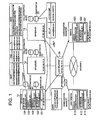
- FIG. 1 illustrates a system configuration of the first embodiment.
- the system illustrated here incorporates three SIP servers (SIP server 11, SIP server 12, SIP server 13) being session management servers, a load balancer 30, a communication device (user terminal) 51 used by a user for performing data communication for a service, and a communication device 52 for providing the service.
- SIP server 11, SIP server 12, SIP server 13 session management servers
- load balancer 30 a communication device 51 used by a user for performing data communication for a service
- communication device 52 for providing the service.
- Three SIP servers and the load balancer 30 are coupled via the LAN 1, and further, the load balancer 30, the communication device 51, and the communication device 52 are coupled via the network 0.
- the SIP server 11 is assigned an IP address of 192.168.10.11, and it is provided with a registrar DB 21 for managing the communication device logging into the SIP server 11, and a call information DB 41 for managing information of a communication session managed by the SIP server 11.
- a software structure of the SIP server 11 incorporates a network interface card (NIC) controller 101 for establishing communicating with other SIP server and the load balancer 30 via the LAN 1, an SIP message processing unit 102 for processing an SIP message, a registrar processing unit 103 for controlling the processing for the registrar DB 21, a session managing unit 104 for controlling the processing for the call information DB 41, and an SIP server searching unit 105 that makes a search for an SIP server to which a target communication device is logged in.
- NIC network interface card
- the SIP server 12 is assigned an IP address of 192.168.10.12, and it is provided with a registrar DB 22 for managing the communication device logging into the SIP server 12 and a call information DB 42 for managing information of a communication session managed by the SIP server 12, having a software structure similar to the SIP server 11.
- the SIP server 13 is assigned an IP address of 192.168.10.13, and it is provided with a registrar DB 23 for managing the communication device logging into the SIP server 13, and a call information DB 43 for managing information of a communication session managed by the SIP server 13, also having a software structure similar to the SIP server 11.
- the load balancer 30 is a device that has functions for receiving a message from the communication device via the network 0 in an integrated manner, and transferring the message to the SIP servers.
- the load balancer is assigned an IP address of 192.168.10.10. It is to be noted that the load balancer 30 used in the present embodiment has a function in that, if another message is received from the same communication device within a predetermined period, the load balancer 30 transfers the message to the SIP server to which a message was transferred just before.
- the software structure of the communication device 51 includes a network interface card (NIC) controller 511 for communicating with the load balancer 30 and the communication device 52 via the network 0, an SIP message processing unit 512 for processing the SIP message, and a service communication device controller 513 for obtaining a service provided by the communication device 52.
- NIC network interface card
- IP address of 192.168.30.11 and SIP-URI of service@hitachi.com are assigned to the communication device 52.
- the software structure of the communication device 52 includes a network interface card (NIC) controller 521 for communicating with the load balancer 30 and the communication device 51 via the network 0, an SIP message processing unit 522 for processing the SIP message, and a service communication device controller 523 for providing a service to the communication device 51.
- NIC network interface card
- FIG. 3 and FIG. 4 are sequence diagrams showing the data communication according to the first embodiment.
- the communication device 51 and the communication device 52 perform processing to log into the SIP servers.
- FIG. 3 is a diagram showing a sequence when the communication device 51 and the communication device 52 perform a login process into the SIP server.
- the communication device 52 performs the login process into the SIP server.
- the communication device 52 performs negotiations for TLS communication with the SIP server, via the load balancer 30 (S1).
- the load balancer 30 which received, from the communication device 52, a message requesting the negotiations for TLS communication, selects an SIP server out of three SIP servers for transferring the message, it transfers the message to the selected SIP server.
- the SIP server 13 is selected, and TLS communication is established between the communication device 52 and the SIP server 13.
- the communication device 52 and the SIP server 13 periodically transmit a message to confirm that a communication session is not shut down. Therefore, while the TLS communication is established between the communication device 52 and the SIP server 13, the load balancer 30 is set so that the message from the communication device 52 is constantly transferred to the SIP server 13.
- the communication device 52 transmits a REGISTER message within the SIP message to the load balancer 30 (S2).
- the load balancer 30 that received the REGISTER message transfers the message to the SIP server 13 (S3).
- the SIP message processing unit 102 transmits to the load balancer an SIP response message directed to the communication device 52 in order to notify success in the location registration (S4).
- the load balancer 30 that received the SIP response message transmits the message to the communication device 52 (S5).
- the login of the communication device 52 to the SIP server is completed, and the communication device 52 waits for a service providing request from the communication device 51.
- the communication device 51 performs the login process to the SIP server.
- the communication device 51 performs negotiations for TLS communication with the SIP server, via the load balancer 30 (S6).
- the load balancer 30 which received from the communication device 51 the message requesting the negotiations for TLS communication, selects an SIP server out of three SIP servers for transferring the message, and transfers the message to the selected SIP server.
- the SIP server 11 is selected, and TLS communication is established between the communication device 51 and the SIP server 11. Subsequently, while the TLS communication is established between the communication device 51 and the SIP server 11, the load balancer 30 transfers the message from the communication device 51 constantly to the SIP server 11.
- the communication device 51 transmits a REGISTER message to the load balancer 30 (S7).
- the load balancer 30 which has received the REGISTER message transfers the message to the SIP server 11 (S8).
- the SIP message processing unit 102 transmits to the load balancer, an SIP response message directed to the communication device 51 in order to notify success in the location registration (S9).
- the load balancer 30 that received the SIP response message transmits the message to the communication device 51 (S10).
- the communication device 51 that has completed the login process requests a servicing from the communication device 52.
- FIG. 4 is a diagram showing a sequence in cases where the communication device 51 that has completed the login process receives the servicing from the communication device 52.
- the communication device 51 requests provision of a service from the communication device 52
- the communication device 51 transmits an INVITE message (S11)
- the load balancer 30 transfers the INVITE message to the SIP server 11 with which the communication device 51 has established TLS communication (S12).
- the SIP server 11 that received the INVITE message processes this INVITE message according to the processing flow as shown in FIG. 5 .
- the registrar processing unit 103 accesses the registrar DB 21, and makes a search for an IP address of the receiver's SIP-URI indicated by a To header of the INVITE message being received (step 1001).
- the processing shifts to step 1007, and the session managing unit 104 of the SIP server 11 records in the call information DB 41 identification information of the communication session represented by Call-ID header of the INVITE message and the information that the communication session is in the state of "calling (waiting for a response from the receiving end)".
- the INVITE message is transmitted to the retrieved IP address (step 1008).
- the SIP server 11 adds the identification information of the SIP server 11 to the Via header of the INVITE message.
- step 1001 if a relevant IP address is not retrieved from the registrar DB 21, in order to find the SIP server that manages the communication device indicated by the SIP-URI, the SIP server searching unit 105 creates an SIP server search request message 81, and transmits the SIP server search request message to LAN 1 via the broadcast communication (step 1003, S13).
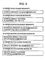
- the SIP server search request message 81 of the present embodiment is made up of the command line including a search target SIP-URI (in FIG. 6 , it is described as "SEARCH_REQUEST sip:service@hitachi.com", and this indicates searching for an SIP server that manages a communication device having the SIP-URI, which is "service@hitachi.com”.
- the SIP server that received the SIP server search request message 81 processes the SIP server search request message 81 according to the processing flow as shown in FIG. 7 .
- the registrar processing unit 103 accesses the registrar DB, and searches the DB for an IP address of the SIP-URI indicated by the command line of the SIP server search request message 81 (step 1012).
- the SIP server searching unit 105 creates an SIP server search response message 82, and transmits the message to a destination indicated by the sending source of the SIP server search request message (step 1014).
- the SIP server search response message 82 of the present embodiment is made up of the command lines indicating a result of searching for the search target SIP-URI (in FIG. 6 , it is described as "SEARCH_RESULT SUCCESS", and this indicates that searching is successful), and identification information for specifying a SIP server that manages the search target SIP-URI (in FIG. 6 , it is described as "IP_ADDRESS: 192.168.10.13", and this indicates that the IP address of the SIP server that manages the search target SIP-URI is 192.168.10.13).
- the SIP server 13 since the communication device 52 is logged into the SIP server 13, the SIP server 13 transmits the SIP server search response message 82 to the SIP server 11 (S14).
- the SIP server 11 which received the SIP server search response message 82 refers to the message and acquires the IP address of the SIP server that manages the communication device (step 1005).
- step 1006 processing shifts to step 1007.
- the session managing unit 104 of the SIP server 11 records in the call information DB 41 identification information of the communication session indicated by the Call-ID header of the INVITE message, an SIP-URI as a sending source of the INVITE message, an SIP-URI as a destination of the INVITE message, and the fact that the communication session is in the state of "calling (waiting for a response from the receiving end)".
- the INVITE message is transmitted to the IP address acquired from the SIP server search response message 82, i.e., in FIG. 4 , to the SIP server 13 (step 1008, S15).
- the SIP server 11 adds identification information of the SIP server 11 to the Via header of the INVITE message.
- the SIP server 13 which received the INVITE message processes this INVITE message, according to the processing flow as shown in FIG. 5 .
- step 1001 the registrar processing unit 103 of the SIP server 13 accesses the registrar DB 23, and searches the DB for the IP address of the receiver SIP-URI indicated by the To header of the INVITE message being received.
- the SIP server 13 is an SIP server to which the communication device 52 is logged in, a relevant IP address can be retrieved from the registrar DB 23.
- the processing of the SIP server 13 shifts to step 1007, and after the session managing unit 104 of the SIP server 13 records in the call information DB 41 identification information of the communication session indicated by the Call-ID header of the INVITE message, identification information of the communication source indicated by the From message, identification information of the communication destination indicated by the To message, and information indicating that the communication session is in the state of "calling (waiting for a response from the receiving end)", the SIP server 13 transmits the INVITE message via the load balancer 30 to the IP address retrieved from the registrar DB 23, i.e., to the communication device 52 (step 1008, S16 and S17) On this occasion, the SIP server 13 adds identification information of the SIP server 13 to the Via header of the INVITE message.
- the SIP message processing unit 522 checks whether or not the communication requested in the message is acceptable. A result of the checking is created in the form of an SIP response message, and the communication device 52 transmits the message to the load balancer 30 (S18). The load balancer 30 transmits the message to the SIP server 13 (S19).
- the SIP message processing unit 102 checks the description of the message, and if it indicates "communication permitted", the session managing unit 104 accesses the call information DB 43, and updates the state of the communication session indicated by the Call-ID header of the message, to "established".
- the session managing unit 104 accesses the call information DB 43, and deletes the entry regarding the communication session indicated by the Call-ID header of the message.
- the SIP server 13 checks the Via header of the SIP response message, and transmits the message to the SIP server 11 (S20).
- the SIP message processing unit 102 updates the call information DB 41 according to the description of the message, and the SIP server 11 transmits the SIP response message to the communication device 51, via the load balancer 30 (S21, S22).
- the SIP message processing unit 512 checks the description of the message, and if it indicates "communication permitted", the service communication device controller 513 performs data communication with the service communication device controller 523 of the communication device 52 (S23), thereby obtaining the service.
- the communication device 51 transmits a BYE message to the load balancer 30 (S24).
- the load balancer 30 which has received the BYE message transmits the message to the SIP server 11 (S25).
- the SIP server 11 which received the BYE message processes the message according to the processing flow as shown in FIG. 5 .
- the SIP server 11 transmits the SIP server search request message 81 by broadcast communication in step 1004 (S26), and receives the SIP server search response message 82 from the SIP server 13 (S27).
- the session managing unit 104 accesses the call information DB 41, and updates the state of the communication session indicated by the Call-ID header of the BYE message to "shutting down communication (waiting for a response from the receiving end)".
- the SIP server 11 transmits the BYE message to the SIP server 13 (S28). At this time, the SIP server 11 adds identification information of the SIP server 11 to the Via header of the BYE message.
- the SIP server 13 which has received the BYE message processes the message according to the processing flow as shown in FIG. 5 .
- the session managing unit 104 accesses the call information DB 43 in step 1007, and the state of the communication session indicated by the Call-ID header of the BYE message is updated to "shutting down communication (waiting for a response from the receiving end)".
- the SIP server 13 transmits the BYE message to the communication device 52 via the load balancer 30 in step 1008 (S29, S30). At this time, the SIP server 13 adds identification information of the SIP server 13 to the Via header of the BYE message.
- the SIP message processing unit 522 performs processing of shutting down the communication requested by the message, and transmits an SIP response message to the load balancer 30 (S31).
- the load balancer 30 transmits the message to the SIP server 13 (S32).
- the session managing unit 104 accesses the call information DB 43, and deletes an entry regarding the communication session indicated by the Call-ID header of the message.
- the SIP server 13 checks the Via header of the SIP response message, and transmits the message to the SIP server 11 (S33).
- the SIP server 11 transmits the SIP response message to the communication device 51 via the load balancer 30 (S34, S35).
- the SIP server search response message 82 is not returned even after a lapse of a predetermined period of time in step 1004 of FIG. 5 , or in cases where a sending source of the message is not obtained from the SIP server search response message 82 in step 1006 of FIG. 5 , the SIP server shifts the processing to step 1009, and the SIP message processing unit 102 creates an SIP response message representing an error occurrence, and returns the message to the sending source of the SIP message. For example, such situation as described above may occur in cases where the communication device 51 transmits an INVITE message to the communication device 52, after the communication device 52 logs out.
- the session management server manages the call information, and need not necessarily have a shared database.
- the load balancing method described in Patent Document 2 updates the shared database every time one message is processed. Therefore, there is a problem in that a shared database having an extremely high processing performance and a high-speed communication means between the session managing server and the shared database are required.
- the load balancing method described in Patent Document 2 has a problem in that if multiple session management servers try to control identical call information simultaneously, the state of the shared database cannot be fixed uniquely.
- neither the high-performance shared database nor the high-speed communication means between the shared database and the session management server is necessary.
- a situation in which the state of the shared database cannot be fixed uniquely will not occur.
- an IP address is used as the identification information for specifying the SIP server described in the SIP server search response message 82, but the present invention is not limited to this example.
- the identification information for specifying the SIP server a combination of the IP address and a port number, a domain name, a host name, a URI, a MAC address, or the like, may be employed, instead of the IP address.
- the configuration in order to make a search for the communication device as a destination of the INVITE message or the BYE message, the configuration is such that the SIP server search message is broadcasted to LAN 1.
- the present invention is not limited to this configuration.
- a configuration is also possible in which an administrator of the LAN 1 sets the multicast communication that reaches multiple SIP servers, and the SIP server transmits an SIP server search message by the use of this multicast communication.
- routers in the LAN 1 may be configured such that when the administrator of the LAN 1 receives a packet directed to this IP address, the packet is transferred to the multiple SIP servers.
- an SIP server manages the IP addresses of other SIP servers, and the SIP server search message is individually transmitted to each of the SIP servers. With this configuration, the load can be distributed even with the SIP servers that belong to different sub domains.
- the communication device 51 is designed to start the processing of shutting down the communication, but the present invention is not limited to this configuration. Shutting down process may be executed from the communication device 52.
- the SIP server searching unit 105 transmits the SIP server search request message 81 by the broadcast communication, the SIP server that has received the SIP server search request message 81 searches the SIP server's own registrar DB, and the SIP server, which is successful in the search, returns the SIP server search response message 82 as a response.
- the second embodiment is distinguished in that an administrative DB is provided, which is accessible from the SIP server and performs management as to which SIP server the currently logged-in communication device is logged into.
- FIG. 8 illustrates a system configuration according to the second embodiment.
- the system illustrated in FIG. 8 incorporates three SIP servers (SIP server 11, SIP server 12, SIP server 13) being session management servers, a load balancer 30, the administrative DB 40 as a feature of the present embodiment, a communication device (also referred to as user terminal) 51 used by a user for performing data communication for a service, and a communication device 52 for providing the service.
- Three SIP servers and the load balancer 30 are coupled via the LAN 1
- three SIP servers and the administrative DB 40 are coupled via the LAN 2
- the load balancer 30, the communication device 51, and the communication device 52 are coupled via the network 0.
- the administrative DB 40 is an information-processing device incorporating the hardware configuration as shown in FIG. 2 .
- an IP address of 192.168.10.11 is assigned to the SIP server 11, and the SIP server 11 is provided with a registrar DB 21 for managing the communication device logging into the SIP server 11, and a call information DB 41 for managing information of a communication session managed by the SIP server 11.
- Software structure of the SIP server 11 incorporates a network interface card (NIC) controller 101 for establishing communicating with another SIP server or the load balancer 30 via the LAN 1, an SIP message processing unit 102 for processing an SIP message, a registrar processing unit 103 for controlling the processing for the registrar DB 21, a session managing unit 104 for controlling the processing for the call information DB 41, and an SIP server searching unit 105 that searches for an SIP server to which a target communication device is logged in.
- NIC network interface card
- the SIP server 12 to which an IP address of 192.168.10.12 is assigned is provided with a registrar DB 22 for managing the communication device that is logged into the SIP server 12, and a call information DB 42 for managing information of a communication session managed by the SIP server 12, and has a software structure similar to the SIP server 11.
- the SIP server 13 to which the IP address of 192.168.10.13 is assigned is provided with a registrar DB 23 for managing the communication device that is logged into the SIP server 13, and a call information DB 43 for managing information of a communication session managed by the SIP server 13, and has a software structure similar to the SIP server 11.
- the load balancer 30 is a device that has functions for receiving a message from the communication device via the network 0 in an integrated manner, and transferring the message to the SIP server.
- the load balancer is assigned an IP address of 192.168.10.10. It is to be noted that the load balancer 30 used in the present embodiment has a function in that if another message is received from the same communication device within a predetermined period, the load balancer 30 transfers the message to the SIP server to which a message was transferred just before.
- the software structure of the communication device 51 includes a network interface card (NIC) controller 511 for communicating with the load balancer 30 and the communication device 52 via the network 0, an SIP message processing unit 512 for processing the SIP message, and a service communication device controller 513 for obtaining a service provided by the communication device 52.
- NIC network interface card
- the IP address of 192.168.30.11 and the SIP-URI of service@hitachi.com are assigned to the communication device 52.
- the software structure of the communication device 52 includes a network interface card (NIC) controller 521 for communicating with the load balancer 30 and the communication device 51 via the network 0, an SIP message processing unit 522 for processing the SIP message, and a service communication device controller 523 for providing a service to the communication device 51.
- NIC network interface card
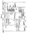
- FIG. 9 and FIG. 10 are sequence diagrams showing data communication according to the second embodiment. Explanations will be omitted as much as possible, concerning steps and messages having the same reference characters as FIG. 3 and FIG. 4 , which have already been explained in the first embodiment.
- the communication device 51 and communication device 52 perform a login process to the SIP servers.
- FIG. 9 is a diagram showing a sequence when the communication device 51 and the communication device 52 perform the login process to the SIP servers.
- the communication device 52 firstly establishes the TLS communication with the SIP server 13, and thereafter transmits a REGISTER message to request the login process (S1 to S3, and S6 to S8).
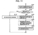
- the SIP server 13 processes the REGISTER message according to the processing flow as shown in FIG. 11 .
- the SIP server 13 which received the REGISTER message, transmits an SIP server search request message 81 to the administrative DB 40 (S301 in FIG. 9 ), and checks whether or not the communication device that transmitted the REGISTER message, i.e., the SIP-URI of the communication device 52, has already been registered in the administrative DB 40.
- An SIP server search response message 82 is received from the administrative DB 40 (S302 in FIG. 9 ), and if the SIP-URI of the communication device 52 has already been registered in the administrative DB 40, the SIP server 13 transmits an SIP response message representing an error, to the communication device 52 via the load balancer 30 (step 2110).
- the SIP-URI of the communication device 52 has not been registered yet in the administrative DB 40, the SIP-URI and the IP address of the communication device 52 are stored in the registrar DB 23, such that they are associated with each other, in step 2103.
- the SIP server 13 transmits an SIP server registration request message 83 in step 2104 (S303 of FIG. 9 ), and associates and registers, in the administrative DB 40, the SIP-URI of the communication device 52 and information of the SIP server to which the communication device 52 is logged in, i.e., the information of the SIP server 13.
- the SIP server registration request message 83 of the present embodiment is made up of command lines including the registration target SIP-URI (in FIG. 6 , it is described as "REGISTER_REQUEST sip:service@hitachi.com", and this indicates that registration of the SIP-URI, service@hitachi.com, is requested) and information of the SIP server that manages the registration target SIP-URI (in FIG. 6 , it is described as "CONTACT: 192.168.10.13: 5060/UDP", and this indicates that the IP address of the SIP server that manages the search target SIP-URI is 192.168.10.13, and No. 5060 port of UDP is waiting for the communication).
- the SIP server 13 transmits to the communication device 52 an SIP response message indicating that the login is successful (step 2105).
- the SIP server registration response message 84 of the present embodiment is made up of command lines, including a registration result of the registration target SIP-URI (in FIG. 6 , it is described as "REGISTER_RESULT SUCCESS", and this indicates that the registration is successful) and a line indicating the registration target SIP-URI (in FIG. 6 , it is described as "SIP-URI: sip:service@hitachi.com”)
- the communication device 51 executes the login process in a similar manner.
- the communication device 51 which has completed the login process requests provision of a service from the communication device 52.
- FIG. 10 is a diagram showing a sequence incases where the communication device 51, which has completed the login process, obtains a service from the communication device 52.
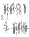
- the SIP server 11 that has received an INVITE message from the communication device 51 via the load balancer 30 processes the INVITE message according to the processing flow as shown in FIG. 12 .
- the SIP server 11 initially determines whether or not the present system employs connection-type communication between the communication device and the SIP server (step 2000).
- step 2006 processing from step 2006 is executed.
- step 2001 a check is made as to whether or not the SIP-URI of the sender of the INVITE message (communication device 51 in FIG. 10 ) is registered in the registrar DB 21.
- step 2006 processing from step 2006 is executed.
- step 2003 the processing shifts to step 2003, and an SIP server search request message 81 is transmitted to the administrative DB 41, to make a search for the SIP server to which the sender of the INVITE message is logged in.
- step 2020 the processing shifts to step 2020, and the SIP response message indicating an error is transmitted to the sender of the INVITE message.
- step 2005 if the SIP server, to which the sender of the INVITE message is logged in, exists, a check is made as to whether or not information regarding this SIP server exists in the Via header of the INVITE message (step 2005) .
- step 2005 if such information does not exist in the Via header of the INVITE message regarding the SIP server to which the sender of the INVITE message is logged in, the SIP server 11 transmits an INVITE message to the SIP server to which the sender of the INVITE message is logged in (step 2012). (On this occasion, it is not necessary for the SIP server 11 to include the information of the SIP server 11 in the Via header of the INVITE message).
- step 2005 if there exists information in the Via header of the INVITE message regarding the SIP server to which the sender of the INVITE message is logged in, the SIP server 11 executes the processing from step 2006.
- the load balancer 30 transfers the INVITE message to the SIP server to which the communication device is not logged in.
- the processing from step 2001 to step 2005 it is possible to transmit the INVITE message to the SIP server to which the communication device is logged in, and the call information DB of the SIP server to which the communication device is logged in can be properly updated.
- the processing shifts to step 2006 after the determination in step 2000.
- step 2006 the SIP server 11 searches to find out whether or not the SIP-URI of the receiver of the INVITE message (communication device 52 in FIG. 10 ) is registered in the registrar DB 21.
- the session managing unit 104 records in the call information DB 41, identification information of the communication session indicated by the Call-ID header of the INVITE message, identification information of the communication source indicated by a "From” message, identification information of the communication destination indicated by a "To” message, and information that the communication session is in the state of "calling (waiting for a response from the receiving end)" (step 2010).
- the SIP server 11 transmits an INVITE message to the IP address that is associated with the SIP-URI (step 2011).
- the SIP server 11 includes, in the Via header of the INVITE message, the information of the SIP server 11.
- the SIP server 11 transmits an SIP server search request message 81 to the administrative DB 40 in step 2008 (S103 in FIG. 10 ), and makes a search for the SIP server to which the receiver of the INVITE message is logged in.
- the session managing unit 104 records in the call information DB 41 the identification information of the communication session indicated by the Call-ID header of the INVITE message and information that the communication session is in the state of "calling (waiting for a response from the receiving end)". Thereafter, the SIP server 11 transmits the INVITE message to the IP address of the SIP server obtained from the SIP server search response message 82 (S15). On this occasion, the SIP server 11 includes in the Via header of the INVITE message the information of the SIP server 11.
- the SIP server 11 transmits to the sender of the INVITE message an SIP response message representing an error (step 2020).
- the SIP server 13 that received the INVITE message from the SIP server 11 processes the INVITE message according to the processing flow shown in FIG. 12 , similar to the processing in the SIP server 11.
- the session managing unit 104 records, in the call information DB 43, identification information of the communication session indicated by the Call-ID header of the INVITE message, and information indicating that the communication session is in the state of "calling (waiting for a response from the receiving end)". Thereafter, the SIP server 13 transmits the INVITE message via the load balancer 30 to the IP address obtained from the registrar DB 23 (S16 and S17).
- the sequence and processing are the same as in the first embodiment, other than that the SIP server, which has received the BYE message, processes the BYE message according to the processing flow shown in FIG. 12 , and explanations will be omitted.
- FIG. 13 is a diagram showing a sequence when the communication device 51 performs logout processing.
- FIG. 13 illustrates the sequence from S51 to S57 when the communication device 51 logs out.
- the communication device 51 When the communication device 51 logs out, the communication device 51 firstly transmits to the load balancer 30 a REGISTER message in which a value of an Expires header is set to zero (S51) .
- the load balancer 30 which received the REGISTER message transfers the REGISTER message to the SIP server 11 (S52).
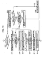
- the SIP server 11 which has received the REGISTER message processes the REGISTER message according to the flow as shown in FIG. 14 .
- the SIP server 11 firstly determines whether or not the present system employs connection-type communication for the communication between the communication device and the SIP server (step 2200).
- step 2204 processing from step 2204 is executed.
- the processing shifts to step 2201.
- the SIP server 11 transmits an SIP server search request message to the administrative DB 40, and makes a search for an SIP server to which the sender of the REGISTER message is logged in (communication device 51 in FIG. 13 ) .
- the processing shifts to step 2230, and an SIP response message representing an error is transmitted to the sender of the REGISTER message.
- the SIP server 11 checks whether the IP address of the retrieved SIP server agrees with its own IP address (step 2203). In step 2203, if the IP addresses do not match, the SIP server 11 transmits the REGISTER message to the SIP server to which the sender of the REGISTER message is logged in. (On this occasion, it is not necessary for the SIP server 11 to include the information of the SIP server 11 in the Via header of the REGISTER message).
- the SIP.server 11 executes the processing from step 2204.
- connectionless communication it may happen that when a certain communication device transmits a REGISTER message, the load balancer 30 transfers the REGISTER message to a SIP server to which the communication device is not logged in.
- the load balancer 30 transfers the REGISTER message to a SIP server to which the communication device is not logged in.
- the processing from step 2201 to step 2203 it is possible to transmit the REGISTER message to the SIP server to which the communication device is logged in, and the registrar DB of the SIP server to which the communication device is logged in can be properly updated.
- step 2204 the SIP server 11 searches the call information DB 41 for an entry that includes the SIP-URI of the sender of the REGISTER message.
- step 2205 if a relevant entry does not exist (No in step 2205), the processing shifts to step 2209.
- step 2205 if a relevant entry exists (Yes in step 2205), the SIP server executes the processing to terminate the pertinent communication. After the termination of the communication, the processing shifts to step 2207.
- step 2207 the SIP server 11 searches the registrar DB 21 to check whether or not the SIP-URI of the sender of the REGISTER message is registered therein.
- step 2208 If a relevant SIP-URI is not registered (No in step 2208), the processing shifts to step 2230, and the SIP server 11 transmits an SIP response message that represents an error to the sender of the REGISTER message.
- the SIP server 11 transmits to the administrative DB 40 an SIP server deletion request message 85 (S53 in FIG. 13 ).
- the SIP server deletion request message 85 of the present embodiment is made up of command line including the deletion target SIP-URI (described in FIG. 6 as "DELETE_REQUEST sip: user@hitachi.com”; this indicates a request for deleting the SIP-URI, "user@hitachi.com”).
- the administrative DB 40 that received the SIP server deletion request message 85 deletes an entry including the SIP-URI that is specified in the SIP server deletion request message 85, and then transmits an SIP server deletion response message 86 to the SIP server 11 (S54 in FIG. 13 ).
- the SIP server deletion response message 86 of the present embodiment is made up of command lines including a deletion result of the deletion target SIP-URI (described in FIG. 6 as "DELETE_RESULT SUCCESS"; this indicates that the deletion is successful), and a line indicating the deletion target SIP-URI (described in FIG. 6 as "SIP-URI: sip:user@hitachi.com”).
- the SIP server 11 that received the SIP server deletion response message 86 shifts the processing to step 2210, and deletes from the registrar DB 21 the entry including the SIP-URI of the sender of the REGISTER message.
- the SIP server 11 transmits the SIP response message to the communication device 51 via the load balancer 30, for notifying the sender of the REGISTER message that the processing is successful (S55 and S56 in FIG. 13 ) .
- the communication device 51 that received the SIP response message terminates the TLS communication (S57).
- the session management server manages the call information, and therefore the administrative DB is only required to record at least the information regarding the SIP server to which the communication device is logged in.
- the shared database is updated every time when one message is processed, and therefore a shared database having an extremely high performance and a high speed communication unit between the session management server and the shared database are required.
- a shared database having an extremely high performance and a high speed communication unit between the session management server and the shared database are required.
- neither such high performance for the administrative DB, nor the high-speed communication means between the SIP server and the administrative DB is necessary.
- the state of the administrative DB can be uniquely fixed, unlike the load balancing method as described in Patent Document 2.
- the shared database is employed instead of the broadcast communication, in order to obtain information of the SIP server that manages the communication device. Therefore, there is an effect in that it is possible to suppress the communications traffic sent and received between the SIP servers.
- an SIP server that received an SIP message obtains information of a second SIP server to which the destination of the SIP message is logged in, and transmits the SIP message to the second SIP server.
- the third embodiment is mainly distinguished in that an administrative DB is provided which is accessible from the SIP server and which manages communication settings for establishing communication with the communication device currently logged in, and in that the SIP server which has received an SIP message obtains communication settings from the administrative DB and communicates with the destination of the SIP message.
- FIG. 15 illustrates a system configuration of the third embodiment.
- the system illustrated here incorporates three SIP servers (SIP server 11, SIP server 12, SIP server 13), the load balancer 30, the administrative DB 40, the communication device 51, and the communication device 52, and three SIP servers and the load balancer 30 are coupled via the LAN 1, three SIP servers and the administrative DB 40 are coupled via the LAN 2, and further, the load balancer 30, the communication device 51, and the communication device 52 are coupled via the network 0.
- SIP server 11, SIP server 12, SIP server 13 the load balancer 30, the administrative DB 40, the communication device 51, and the communication device 52, and three SIP servers and the load balancer 30 are coupled via the LAN 1
- three SIP servers and the administrative DB 40 are coupled via the LAN 2
- the load balancer 30, the communication device 51, and the communication device 52 are coupled via the network 0.
- the SIP server 11 is assigned an IP address of 192.168.10.11, and it is further provided with the registrar DB 21.
- the SIP server 12 is assigned an IP address of 192.168.10.12, and it is further provided with the registrar DB 22.
- the SIP server 13 is assigned an IP address of 192.168.10.13, and it is further provided with the registrar DB 23.
- the load balancer is assigned an IP address of 192.168.10.10. It is to be noted that also the load balancer 30 used in the present embodiment has a function in that if another message is received from the same communication device within a predetermined period, the load balancer 30 transfers the message to the SIP server to which a message was transferred just before.
- IP address of 192.168.20.11 and the SIP-URI of user@hitachi.com are assigned to the communication device 51.
- IP address of 192.168.30.11 and the SIP-URI of service@hitachi.com are assigned to the communication device 52.
- the software structures of the communication device 51 and the communication device 52 are the same as the software structures of the communication device 51 and the communication device 52 according to the second embodiment.
- the administrative DB 40 of the present embodiment is made up of a call information table 401 for recording the call information managed by the SIP server 11, SIP server 12, and SIP server 13, and a communication shared information table 402 for recording communication settings for the SIP server 11, SIP server 12, and SIP server 13 to perform communication with the communication device 51 and communication device 52.
- the call information table 401 records a Call-ID as identification information of a communication session, the SIP-URI of a communication session sender, the SIP-URI of a communication session receiver, and a state of the communication session.
- the communication shared information table 402 records the SIP-URI being the identification information of a communication device, access point information (i.e., a combination of IP address, port number, and transport layer protocol type) in establishing communication with the communication device, an encryption algorithm type used for encrypted communication with the communication device, a value of key used for the encrypted communication, and a sequence number for identifying the sequence of the message.
- access point information i.e., a combination of IP address, port number, and transport layer protocol type
- FIG. 16 and FIG. 17 are sequence diagrams, each showing the data communication according to the third embodiment. Explanations are omitted as much as possible concerning steps and messages having the same reference symbols as FIG. 3 and FIG. 4 , which have already been explained in the first embodiment.
- FIG. 16 is a diagram showing the sequence in cases where the communication device 51 performs a login process to the SIP server.
- the SIP server 11 when the communication device 51 has established encrypted communication with the SIP server (in FIG. 16 , SIP server 11) by performing negotiation for the encrypted communication (S6), the SIP server 11 registers in the administrative DB 40 communication settings of the established encrypted communication (S401, S402).
- the SIP server 11 which has received a REGISTER message that the communication device 51 transmitted, acquires from the administrative DB 40 the communication settings between the SIP server 11 and the communication device 51 (S403, S404), and decrypts the REGISTER message by using the settings.
- the SIP server 11 acquires the communication settings with the communication device 51 from the administrative DB (S407, S408), encrypts the SIP response message by using the settings, and transmits the encrypted message to the communication device 51 (S9, S10).
- the SIP server 11 updates the communication settings between the SIP server 11 and the communication device 51 (S409, S410).
- the SIP server acquires from the administrative DB 40 the communication settings between the SIP server and the communication device, performs encryption and decryption processing, and simultaneously updates the communication settings recorded in the administrative DB 40 every time the SIP server exchanges an SIP message and an SIP response message with the communication device.
- the processing for acquiring the communication settings from the administrative DB 40 and updating thereof will be omitted.
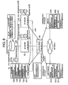
- FIG. 17 is a diagram showing a sequence in cases where the communication device 51 establishes communication with the communication device 52.
- the communication device 51 transmits an INVITE message to the load balancer 30 (S501).
- the load balancer Upon receipt of the INVITE message, the load balancer selects an SIP server out of three SIP servers to transfer the INVITE message, and transfers the INVITE message to the selected SIP server (S502) .
- FIG. 17 shows cases where the SIP server 11 is selected as the transfer target SIP server.
- the SIP server 11 that received the INVITE message searches the call information table 402 in the administrative DB 40 to check whether or not the call information having the identification information of the communication session indicated by the Call-ID header of the INVITE message is registered (S503, S504).
- the SIP server transmits an SIP response message via the load balancer 30 to the communication device 51, giving notification that the communication session is already being processed.
- the SIP server transmits a call information update request message to the call information table 402 in the administrative DB, and records in the call information table 402 identification information of the communication session indicated by the Call-ID header of the INVITE message, an SIP-URI of the INVITE message sender, an SIP-URI of the INVITE message destination, and the fact that the communication session is in the state of "calling (waiting for a response from the receiving end) " (S505, S506).
- the SIP server 11 transmits the INVITE message, via the load balancer 30, to the communication device 52 that is assigned as the destination of the INVITE message (S507, S508).
- the communication device 52 that received the INVITE message creates an SIP response message for the INVITE message, and transmits the message to the load balancer 30 (S509).
- the load balancer 30 Upon receipt of the SIP response message, the load balancer 30 selects from three SIP servers an SIP server for transferring the SIP response message, and transfers the SIP response message to the SIP server being selected (S510).
- FIG. 17 illustrates cases where the SIP server 13 is selected as the transfer target SIP server.
- the SIP server 13 that received the SIP response message searches the call information table 402 of the administrative DB 40, to check whether or not the call information having the identification information of the communication session indicated by the Call-ID header of the SIP response message is registered (S511, S512).
- the SIP server 13 transmits, via the load balancer 30 to the communication device 52, an SIP response message indicating that an error has occurred.
- the SIP server 13 transmits a call information update request message to the call information table 402 in the administrative DB 40, and deletes the call information of the communication session indicated by the Call-ID header of the SIP response message in the call information table 402.
- the SIP server 13 transmits the call information update request message to the call information table 402 of the administrative DB 40, and updates the state of the call information of the communication session indicated by the Call-ID header of the SIP response message in the call information table 402 to "established” (S513, 5514).
- the SIP server 13 transmits the SIP response message, via the load balancer 30, to the communication device 51 that is assigned as a sending destination of the SIP response message (S515, S516).
- the SIP server acquires call information regarding the communication session from the administrative DB 40 and processes the message, every time the SIP server receives an INVITE message from and transmits an SIP response message for the INVITE message to the communication device.
- the SIP server 11 updates the call information recorded in the administrative DB 40. It is to be noted here that in the present embodiment, upon receipt of a BYE message or an SIP response message for the BYE message, the SIP server 11 acquires, from the administrative DB 40, call information regarding the communication session, and processes the message. Further, in accordance with the result after the processing, the SIP serer 11 updates the call information recorded in the administrative DB 40.
- a shared database is provided that is accessible from the SIP server, and that records communication settings for performing communication with the communication device. Therefore, the SIP server that received the SIP message or the SIP response message, refers to the shared database and acquires the communication settings, thereby producing an effect in that even the SIP server, to which the sending source of the SIP message or the SIP response message does not log in, is capable of processing the message (for example, if encrypted communication is performed, decryption can be properly carried out).
- the SIP server acquires the communication settings by referring to the shared database, when the SIP message or the SIP response message is transmitted. Therefore, there is an effect in the message can be directly transmitted to the communication device, without transmitting the message to the SIP server to which the communication device as a sending destination of the SIP message or the SIP response message is logged in.
Applications Claiming Priority (1)
| Application Number | Priority Date | Filing Date | Title |
|---|---|---|---|
| JP2007041670A JP2008205988A (ja) | 2007-02-22 | 2007-02-22 | データ通信システムおよびセッション管理サーバ |
Publications (1)
| Publication Number | Publication Date |
|---|---|
| EP1962459A2 true EP1962459A2 (de) | 2008-08-27 |
Family
ID=39643031
Family Applications (1)
| Application Number | Title | Priority Date | Filing Date |
|---|---|---|---|
| EP20080003203 Withdrawn EP1962459A2 (de) | 2007-02-22 | 2008-02-21 | Datenkommunikationssystem und Sitzungsverwaltungsserver |
Country Status (4)
| Country | Link |
|---|---|
| US (1) | US20080256224A1 (de) |
| EP (1) | EP1962459A2 (de) |
| JP (1) | JP2008205988A (de) |
| CN (1) | CN101252581A (de) |
Cited By (2)
| Publication number | Priority date | Publication date | Assignee | Title |
|---|---|---|---|---|
| CN104992288A (zh) * | 2015-07-01 | 2015-10-21 | 上海众材工程检测有限公司 | 一种楼宇能耗监测信息系统 |
| EP3072285A4 (de) * | 2013-11-18 | 2016-11-16 | Ricoh Co Ltd | Steuerungssystem, kommunikationssystem, computerprogramm, steuerungsverfahren und computerprogrammprodukt |
Families Citing this family (117)
| Publication number | Priority date | Publication date | Assignee | Title |
|---|---|---|---|---|
| US7343413B2 (en) | 2000-03-21 | 2008-03-11 | F5 Networks, Inc. | Method and system for optimizing a network by independently scaling control segments and data flow |
| US8380854B2 (en) | 2000-03-21 | 2013-02-19 | F5 Networks, Inc. | Simplified method for processing multiple connections from the same client |
| US8837465B2 (en) | 2008-04-02 | 2014-09-16 | Twilio, Inc. | System and method for processing telephony sessions |
| CN102027721B (zh) | 2008-04-02 | 2015-05-13 | 特维里奥公司 | 处理电话会话的系统和方法 |
| US8806053B1 (en) | 2008-04-29 | 2014-08-12 | F5 Networks, Inc. | Methods and systems for optimizing network traffic using preemptive acknowledgment signals |
| US8516126B2 (en) * | 2008-09-24 | 2013-08-20 | International Business Machines Corporation | Processing SIP messages based on multiple cores |
| US8964726B2 (en) | 2008-10-01 | 2015-02-24 | Twilio, Inc. | Telephony web event system and method |
| US8566444B1 (en) | 2008-10-30 | 2013-10-22 | F5 Networks, Inc. | Methods and system for simultaneous multiple rules checking |
| US20100211544A1 (en) * | 2009-02-19 | 2010-08-19 | Jyshyang Chen | System with session synchronization |
| EP2404412B1 (de) | 2009-03-02 | 2019-05-01 | Twilio Inc. | Verfahren und system für ein mehrteilnehmer-telefonnetzwerk |
| US10157280B2 (en) | 2009-09-23 | 2018-12-18 | F5 Networks, Inc. | System and method for identifying security breach attempts of a website |
| US9210275B2 (en) | 2009-10-07 | 2015-12-08 | Twilio, Inc. | System and method for running a multi-module telephony application |
| US8868961B1 (en) | 2009-11-06 | 2014-10-21 | F5 Networks, Inc. | Methods for acquiring hyper transport timing and devices thereof |
| US10721269B1 (en) | 2009-11-06 | 2020-07-21 | F5 Networks, Inc. | Methods and system for returning requests with javascript for clients before passing a request to a server |
| US9141625B1 (en) | 2010-06-22 | 2015-09-22 | F5 Networks, Inc. | Methods for preserving flow state during virtual machine migration and devices thereof |
| US9459926B2 (en) | 2010-06-23 | 2016-10-04 | Twilio, Inc. | System and method for managing a computing cluster |
| US20120208495A1 (en) | 2010-06-23 | 2012-08-16 | Twilio, Inc. | System and method for monitoring account usage on a platform |
| US9338064B2 (en) | 2010-06-23 | 2016-05-10 | Twilio, Inc. | System and method for managing a computing cluster |
| US9459925B2 (en) | 2010-06-23 | 2016-10-04 | Twilio, Inc. | System and method for managing a computing cluster |
| US9590849B2 (en) | 2010-06-23 | 2017-03-07 | Twilio, Inc. | System and method for managing a computing cluster |
| US10015286B1 (en) | 2010-06-23 | 2018-07-03 | F5 Networks, Inc. | System and method for proxying HTTP single sign on across network domains |
| US8838707B2 (en) | 2010-06-25 | 2014-09-16 | Twilio, Inc. | System and method for enabling real-time eventing |
| JP5693065B2 (ja) * | 2010-07-06 | 2015-04-01 | キヤノン株式会社 | 通信端末、通信端末の制御方法及びプログラム |
| US8908545B1 (en) | 2010-07-08 | 2014-12-09 | F5 Networks, Inc. | System and method for handling TCP performance in network access with driver initiated application tunnel |
| US8347100B1 (en) | 2010-07-14 | 2013-01-01 | F5 Networks, Inc. | Methods for DNSSEC proxying and deployment amelioration and systems thereof |
| US9083760B1 (en) | 2010-08-09 | 2015-07-14 | F5 Networks, Inc. | Dynamic cloning and reservation of detached idle connections |
| US8630174B1 (en) | 2010-09-14 | 2014-01-14 | F5 Networks, Inc. | System and method for post shaping TCP packetization |
| US8886981B1 (en) | 2010-09-15 | 2014-11-11 | F5 Networks, Inc. | Systems and methods for idle driven scheduling |
| US8804504B1 (en) | 2010-09-16 | 2014-08-12 | F5 Networks, Inc. | System and method for reducing CPU load in processing PPP packets on a SSL-VPN tunneling device |
| WO2012058486A2 (en) | 2010-10-29 | 2012-05-03 | F5 Networks, Inc. | Automated policy builder |
| US9554276B2 (en) | 2010-10-29 | 2017-01-24 | F5 Networks, Inc. | System and method for on the fly protocol conversion in obtaining policy enforcement information |
| US8627467B2 (en) | 2011-01-14 | 2014-01-07 | F5 Networks, Inc. | System and method for selectively storing web objects in a cache memory based on policy decisions |
| US10135831B2 (en) | 2011-01-28 | 2018-11-20 | F5 Networks, Inc. | System and method for combining an access control system with a traffic management system |
| US8649268B2 (en) | 2011-02-04 | 2014-02-11 | Twilio, Inc. | Method for processing telephony sessions of a network |
| US9578126B1 (en) | 2011-04-30 | 2017-02-21 | F5 Networks, Inc. | System and method for automatically discovering wide area network optimized routes and devices |
| US20140044123A1 (en) | 2011-05-23 | 2014-02-13 | Twilio, Inc. | System and method for real time communicating with a client application |
| US9648006B2 (en) | 2011-05-23 | 2017-05-09 | Twilio, Inc. | System and method for communicating with a client application |
| US9398622B2 (en) | 2011-05-23 | 2016-07-19 | Twilio, Inc. | System and method for connecting a communication to a client |
| US9246819B1 (en) | 2011-06-20 | 2016-01-26 | F5 Networks, Inc. | System and method for performing message-based load balancing |
| EP2759123B1 (de) | 2011-09-21 | 2018-08-15 | Twilio, Inc. | System und verfahren zum autorisieren und verbinden von anwendungsentwicklern und -benutzern |
| US10182147B2 (en) | 2011-09-21 | 2019-01-15 | Twilio Inc. | System and method for determining and communicating presence information |
| FR2984063A1 (fr) * | 2011-12-12 | 2013-06-14 | France Telecom | Enrichissement, gestion de contenus multimedia et etablissement d'une communication en fonction de contenus multimedia enrichis |
| US9270766B2 (en) | 2011-12-30 | 2016-02-23 | F5 Networks, Inc. | Methods for identifying network traffic characteristics to correlate and manage one or more subsequent flows and devices thereof |
| EP2813044A1 (de) * | 2012-02-07 | 2014-12-17 | Telefonaktiebolaget L M Ericsson (publ) | Sitzungspersistente daten und verwendungsverfahren dafür |
| US9495227B2 (en) | 2012-02-10 | 2016-11-15 | Twilio, Inc. | System and method for managing concurrent events |
| US10230566B1 (en) | 2012-02-17 | 2019-03-12 | F5 Networks, Inc. | Methods for dynamically constructing a service principal name and devices thereof |
| US9172753B1 (en) | 2012-02-20 | 2015-10-27 | F5 Networks, Inc. | Methods for optimizing HTTP header based authentication and devices thereof |
| US9231879B1 (en) | 2012-02-20 | 2016-01-05 | F5 Networks, Inc. | Methods for policy-based network traffic queue management and devices thereof |
| WO2013163648A2 (en) | 2012-04-27 | 2013-10-31 | F5 Networks, Inc. | Methods for optimizing service of content requests and devices thereof |
| US20130304928A1 (en) | 2012-05-09 | 2013-11-14 | Twilio, Inc. | System and method for managing latency in a distributed telephony network |
| US9602586B2 (en) | 2012-05-09 | 2017-03-21 | Twilio, Inc. | System and method for managing media in a distributed communication network |
| US9240941B2 (en) | 2012-05-09 | 2016-01-19 | Twilio, Inc. | System and method for managing media in a distributed communication network |
| US9167041B2 (en) | 2012-06-01 | 2015-10-20 | International Business Machines Corporation | Maintaining session initiation protocol application session affinity in SIP container cluster environments |
| US9247062B2 (en) | 2012-06-19 | 2016-01-26 | Twilio, Inc. | System and method for queuing a communication session |
| US8737962B2 (en) | 2012-07-24 | 2014-05-27 | Twilio, Inc. | Method and system for preventing illicit use of a telephony platform |
| US8938053B2 (en) | 2012-10-15 | 2015-01-20 | Twilio, Inc. | System and method for triggering on platform usage |
| US8948356B2 (en) | 2012-10-15 | 2015-02-03 | Twilio, Inc. | System and method for routing communications |
| US9253254B2 (en) | 2013-01-14 | 2016-02-02 | Twilio, Inc. | System and method for offering a multi-partner delegated platform |
| US10375155B1 (en) | 2013-02-19 | 2019-08-06 | F5 Networks, Inc. | System and method for achieving hardware acceleration for asymmetric flow connections |
| US9282124B2 (en) | 2013-03-14 | 2016-03-08 | Twilio, Inc. | System and method for integrating session initiation protocol communication in a telecommunications platform |
| US9001666B2 (en) | 2013-03-15 | 2015-04-07 | Twilio, Inc. | System and method for improving routing in a distributed communication platform |
| US9160696B2 (en) | 2013-06-19 | 2015-10-13 | Twilio, Inc. | System for transforming media resource into destination device compatible messaging format |
| US9225840B2 (en) | 2013-06-19 | 2015-12-29 | Twilio, Inc. | System and method for providing a communication endpoint information service |
| US9338280B2 (en) | 2013-06-19 | 2016-05-10 | Twilio, Inc. | System and method for managing telephony endpoint inventory |
| US9483328B2 (en) | 2013-07-19 | 2016-11-01 | Twilio, Inc. | System and method for delivering application content |
| EP2833307A1 (de) | 2013-07-30 | 2015-02-04 | Google, Inc. | Handhabung von Suchanfragen |
| US9274858B2 (en) | 2013-09-17 | 2016-03-01 | Twilio, Inc. | System and method for tagging and tracking events of an application platform |
| US9137127B2 (en) | 2013-09-17 | 2015-09-15 | Twilio, Inc. | System and method for providing communication platform metadata |
| US9338018B2 (en) | 2013-09-17 | 2016-05-10 | Twilio, Inc. | System and method for pricing communication of a telecommunication platform |
| US10637929B1 (en) * | 2013-09-23 | 2020-04-28 | Ribbon Communications Operating Company, Inc. | Methods and apparatus for storing and/or retrieving session state information |
| US9553799B2 (en) | 2013-11-12 | 2017-01-24 | Twilio, Inc. | System and method for client communication in a distributed telephony network |
| US9325624B2 (en) | 2013-11-12 | 2016-04-26 | Twilio, Inc. | System and method for enabling dynamic multi-modal communication |
| US10187317B1 (en) | 2013-11-15 | 2019-01-22 | F5 Networks, Inc. | Methods for traffic rate control and devices thereof |
| JP6244894B2 (ja) * | 2013-12-24 | 2017-12-13 | 富士通株式会社 | 通信システム、通信方法および呼制御サーバ装置 |
| WO2015122177A1 (ja) * | 2014-02-12 | 2015-08-20 | 日本電気株式会社 | 情報処理装置、通信方法、ネットワーク制御装置、ネットワーク制御方法、およびプログラム |
| US9344573B2 (en) | 2014-03-14 | 2016-05-17 | Twilio, Inc. | System and method for a work distribution service |
| US9226217B2 (en) | 2014-04-17 | 2015-12-29 | Twilio, Inc. | System and method for enabling multi-modal communication |
| US10015143B1 (en) | 2014-06-05 | 2018-07-03 | F5 Networks, Inc. | Methods for securing one or more license entitlement grants and devices thereof |
| US9516101B2 (en) | 2014-07-07 | 2016-12-06 | Twilio, Inc. | System and method for collecting feedback in a multi-tenant communication platform |
| US9774687B2 (en) | 2014-07-07 | 2017-09-26 | Twilio, Inc. | System and method for managing media and signaling in a communication platform |
| US9246694B1 (en) | 2014-07-07 | 2016-01-26 | Twilio, Inc. | System and method for managing conferencing in a distributed communication network |
| US9251371B2 (en) | 2014-07-07 | 2016-02-02 | Twilio, Inc. | Method and system for applying data retention policies in a computing platform |
| US11838851B1 (en) | 2014-07-15 | 2023-12-05 | F5, Inc. | Methods for managing L7 traffic classification and devices thereof |
| US10122630B1 (en) | 2014-08-15 | 2018-11-06 | F5 Networks, Inc. | Methods for network traffic presteering and devices thereof |
| US9363301B2 (en) | 2014-10-21 | 2016-06-07 | Twilio, Inc. | System and method for providing a micro-services communication platform |
| US10182013B1 (en) | 2014-12-01 | 2019-01-15 | F5 Networks, Inc. | Methods for managing progressive image delivery and devices thereof |
| US11895138B1 (en) | 2015-02-02 | 2024-02-06 | F5, Inc. | Methods for improving web scanner accuracy and devices thereof |
| US9477975B2 (en) | 2015-02-03 | 2016-10-25 | Twilio, Inc. | System and method for a media intelligence platform |
| US10834065B1 (en) | 2015-03-31 | 2020-11-10 | F5 Networks, Inc. | Methods for SSL protected NTLM re-authentication and devices thereof |
| US10505818B1 (en) | 2015-05-05 | 2019-12-10 | F5 Networks. Inc. | Methods for analyzing and load balancing based on server health and devices thereof |
| US11350254B1 (en) | 2015-05-05 | 2022-05-31 | F5, Inc. | Methods for enforcing compliance policies and devices thereof |
| US9948703B2 (en) | 2015-05-14 | 2018-04-17 | Twilio, Inc. | System and method for signaling through data storage |
| US10419891B2 (en) | 2015-05-14 | 2019-09-17 | Twilio, Inc. | System and method for communicating through multiple endpoints |
| CN105516245B (zh) * | 2015-11-25 | 2018-12-14 | 国家计算机网络与信息安全管理中心 | 一种基于流的负载均衡的系统以及实现方法 |
| US11757946B1 (en) | 2015-12-22 | 2023-09-12 | F5, Inc. | Methods for analyzing network traffic and enforcing network policies and devices thereof |
| US10447773B2 (en) * | 2015-12-29 | 2019-10-15 | General Motors Llc | Aggregating vehicle-related big data |
| US10404698B1 (en) | 2016-01-15 | 2019-09-03 | F5 Networks, Inc. | Methods for adaptive organization of web application access points in webtops and devices thereof |
| US11178150B1 (en) | 2016-01-20 | 2021-11-16 | F5 Networks, Inc. | Methods for enforcing access control list based on managed application and devices thereof |
| US10797888B1 (en) | 2016-01-20 | 2020-10-06 | F5 Networks, Inc. | Methods for secured SCEP enrollment for client devices and devices thereof |
| US10659349B2 (en) | 2016-02-04 | 2020-05-19 | Twilio Inc. | Systems and methods for providing secure network exchanged for a multitenant virtual private cloud |
| US10686902B2 (en) | 2016-05-23 | 2020-06-16 | Twilio Inc. | System and method for a multi-channel notification service |
| US10063713B2 (en) | 2016-05-23 | 2018-08-28 | Twilio Inc. | System and method for programmatic device connectivity |
| US10791088B1 (en) | 2016-06-17 | 2020-09-29 | F5 Networks, Inc. | Methods for disaggregating subscribers via DHCP address translation and devices thereof |
| US11063758B1 (en) | 2016-11-01 | 2021-07-13 | F5 Networks, Inc. | Methods for facilitating cipher selection and devices thereof |
| US10505792B1 (en) | 2016-11-02 | 2019-12-10 | F5 Networks, Inc. | Methods for facilitating network traffic analytics and devices thereof |
| US11496438B1 (en) | 2017-02-07 | 2022-11-08 | F5, Inc. | Methods for improved network security using asymmetric traffic delivery and devices thereof |
| US10791119B1 (en) | 2017-03-14 | 2020-09-29 | F5 Networks, Inc. | Methods for temporal password injection and devices thereof |
| US10812266B1 (en) | 2017-03-17 | 2020-10-20 | F5 Networks, Inc. | Methods for managing security tokens based on security violations and devices thereof |
| US10931662B1 (en) | 2017-04-10 | 2021-02-23 | F5 Networks, Inc. | Methods for ephemeral authentication screening and devices thereof |
| US10972453B1 (en) | 2017-05-03 | 2021-04-06 | F5 Networks, Inc. | Methods for token refreshment based on single sign-on (SSO) for federated identity environments and devices thereof |
| US11122042B1 (en) | 2017-05-12 | 2021-09-14 | F5 Networks, Inc. | Methods for dynamically managing user access control and devices thereof |
| US11343237B1 (en) | 2017-05-12 | 2022-05-24 | F5, Inc. | Methods for managing a federated identity environment using security and access control data and devices thereof |
| US11122083B1 (en) | 2017-09-08 | 2021-09-14 | F5 Networks, Inc. | Methods for managing network connections based on DNS data and network policies and devices thereof |
| US11658995B1 (en) | 2018-03-20 | 2023-05-23 | F5, Inc. | Methods for dynamically mitigating network attacks and devices thereof |
| US11044200B1 (en) | 2018-07-06 | 2021-06-22 | F5 Networks, Inc. | Methods for service stitching using a packet header and devices thereof |
| CN110445882A (zh) | 2019-09-19 | 2019-11-12 | 腾讯科技(深圳)有限公司 | 通信连接方法、装置、计算机设备及存储介质 |
| CN112039729B (zh) * | 2020-08-28 | 2022-04-01 | 中移(杭州)信息技术有限公司 | 设备识别方法、服务器、电子设备和存储介质 |
Citations (2)
| Publication number | Priority date | Publication date | Assignee | Title |
|---|---|---|---|---|
| JP3730545B2 (ja) | 2001-08-16 | 2006-01-05 | 日本電信電話株式会社 | サービス制御アプリケーション実行方法及びシステム |
| JP2007041670A (ja) | 2005-08-01 | 2007-02-15 | Matsushita Electric Ind Co Ltd | 半導体集積回路の設計データ構造、設計装置および設計方法 |
Family Cites Families (11)
| Publication number | Priority date | Publication date | Assignee | Title |
|---|---|---|---|---|
| CA2287813C (en) * | 1998-10-22 | 2005-03-29 | At&T Corp. | System and method for network load balancing |
| US6564261B1 (en) * | 1999-05-10 | 2003-05-13 | Telefonaktiebolaget Lm Ericsson (Publ) | Distributed system to intelligently establish sessions between anonymous users over various networks |
| US7606909B1 (en) * | 2001-02-20 | 2009-10-20 | Michael Ely | Method and apparatus for a business contact center |
| US9015297B2 (en) * | 2002-01-15 | 2015-04-21 | Avaya Inc. | Communication application server for converged communication services |
| JP3855909B2 (ja) * | 2002-10-23 | 2006-12-13 | 株式会社日立製作所 | ポリシ設定可能なピアツーピア通信システム |
| JP4345368B2 (ja) * | 2003-06-17 | 2009-10-14 | 株式会社日立製作所 | プレゼンス管理装置および情報配信システム |
| EP1503558A1 (de) * | 2003-08-01 | 2005-02-02 | Siemens Aktiengesellschaft | Verbindung von Teilnehmern in hybriden Kommunikationsnetzen |
| WO2006048759A1 (en) * | 2004-11-08 | 2006-05-11 | Nokia Corporation | Method enabling sessions and applications in instant messaging and presence serviced |
| JP4830503B2 (ja) * | 2006-01-18 | 2011-12-07 | 株式会社日立製作所 | 個人情報を保護した通信セッション確立仲介システムおよび方法 |
| JP4770494B2 (ja) * | 2006-02-03 | 2011-09-14 | 株式会社日立製作所 | 暗号通信方法およびシステム |
| US8862746B2 (en) * | 2006-05-17 | 2014-10-14 | Sonim Technologies, Inc. | Systems and methods for integrating applications on user equipment utilizing special URI control messages |
-
2007
- 2007-02-22 JP JP2007041670A patent/JP2008205988A/ja active Pending
-
2008
- 2008-02-21 EP EP20080003203 patent/EP1962459A2/de not_active Withdrawn
- 2008-02-22 US US12/071,592 patent/US20080256224A1/en not_active Abandoned
- 2008-02-22 CN CNA2008100808499A patent/CN101252581A/zh active Pending
Patent Citations (2)
| Publication number | Priority date | Publication date | Assignee | Title |
|---|---|---|---|---|
| JP3730545B2 (ja) | 2001-08-16 | 2006-01-05 | 日本電信電話株式会社 | サービス制御アプリケーション実行方法及びシステム |
| JP2007041670A (ja) | 2005-08-01 | 2007-02-15 | Matsushita Electric Ind Co Ltd | 半導体集積回路の設計データ構造、設計装置および設計方法 |
Cited By (3)
| Publication number | Priority date | Publication date | Assignee | Title |
|---|---|---|---|---|
| EP3072285A4 (de) * | 2013-11-18 | 2016-11-16 | Ricoh Co Ltd | Steuerungssystem, kommunikationssystem, computerprogramm, steuerungsverfahren und computerprogrammprodukt |
| US10187219B2 (en) | 2013-11-18 | 2019-01-22 | Ricoh Company, Limited | Control system, communication system, computer program, controlling method, and computer program product |
| CN104992288A (zh) * | 2015-07-01 | 2015-10-21 | 上海众材工程检测有限公司 | 一种楼宇能耗监测信息系统 |
Also Published As
| Publication number | Publication date |
|---|---|
| JP2008205988A (ja) | 2008-09-04 |
| CN101252581A (zh) | 2008-08-27 |
| US20080256224A1 (en) | 2008-10-16 |
Similar Documents
| Publication | Publication Date | Title |
|---|---|---|
| EP1962459A2 (de) | Datenkommunikationssystem und Sitzungsverwaltungsserver | |
| JP4690767B2 (ja) | ネットワークシステム、サーバ装置および通信方法 | |
| JP5143125B2 (ja) | ドメイン間情報通信のための認証方法、システム、およびその装置 | |
| US8499083B2 (en) | Relay device and communication system | |
| KR100924692B1 (ko) | 데이터 전송시스템, 정보처리장치 및 방법, 데이터중계장치 및 방법과, 기록매체 | |
| US20070078986A1 (en) | Techniques for reducing session set-up for real-time communications over a network | |
| US20070162744A1 (en) | Data communication method and data communication system | |
| JP5239341B2 (ja) | ゲートウェイ、中継方法及びプログラム | |
| US8874911B2 (en) | Terminal device, system, connection management server, and computer readable medium | |
| JP2008181427A (ja) | シングルサインオンシステム、情報端末装置、シングルサインオンサーバ、プログラム | |
| JP2017108417A (ja) | ネットワーク通信システムおよび方法 | |
| US20090067419A1 (en) | Transmission control apparatus and method | |
| US7818437B2 (en) | Connection management system, connection management method, and management server | |
| US20050135269A1 (en) | Automatic configuration of a virtual private network | |
| US11716222B2 (en) | Communications bridge | |
| US20100257274A1 (en) | Communication system, communication method, and shared-authentication apparatus | |
| US20100268833A1 (en) | Communication system, communication method, and communication session centralizing apparatus | |
| US10880393B2 (en) | Method for caching a piece of content in a content distribution network | |
| US11310191B2 (en) | Receiving device, receiving device control method, network system, network system control method, and medium | |
| JP5022474B2 (ja) | サーバ装置、通信方法およびプログラム | |
| US7904506B2 (en) | Context information management system | |
| US20100250758A1 (en) | Communication system, communication method, and server management apparatus | |
| JP5415388B2 (ja) | 仮想通信路接続システム、制御方法、制御プログラム、第1の端末及び第2の端末 | |
| JP5028995B2 (ja) | サービス提供装置、認証方法及び認証プログラム | |
| JP5233905B2 (ja) | 通信制御装置 |
Legal Events
| Date | Code | Title | Description |
|---|---|---|---|
| PUAI | Public reference made under article 153(3) epc to a published international application that has entered the european phase |
Free format text: ORIGINAL CODE: 0009012 |
|
| 17P | Request for examination filed |
Effective date: 20080319 |
|
| AK | Designated contracting states |
Kind code of ref document: A2 Designated state(s): AT BE BG CH CY CZ DE DK EE ES FI FR GB GR HR HU IE IS IT LI LT LU LV MC MT NL NO PL PT RO SE SI SK TR |
|
| AX | Request for extension of the european patent |
Extension state: AL BA MK RS |
|
| RIC1 | Information provided on ipc code assigned before grant |
Ipc: H04L 29/06 20060101ALI20090327BHEP Ipc: H04L 29/08 20060101AFI20090327BHEP |
|
| RTI1 | Title (correction) |
Free format text: DATA COMMUNICATION SYSTEM AND SESSION MANAGEMENT SERVER FOR LOADBALANCING |
|
| 18W | Application withdrawn |
Effective date: 20110824 |
|
| D18W | Application withdrawn (deleted) | ||
| STAA | Information on the status of an ep patent application or granted ep patent |
Free format text: STATUS: THE APPLICATION IS DEEMED TO BE WITHDRAWN |
|
| 18D | Application deemed to be withdrawn |
Effective date: 20120901 |