EP1962026A1 - Indoor machine of air conditioner - Google Patents
Indoor machine of air conditioner Download PDFInfo
- Publication number
- EP1962026A1 EP1962026A1 EP06822220A EP06822220A EP1962026A1 EP 1962026 A1 EP1962026 A1 EP 1962026A1 EP 06822220 A EP06822220 A EP 06822220A EP 06822220 A EP06822220 A EP 06822220A EP 1962026 A1 EP1962026 A1 EP 1962026A1
- Authority
- EP
- European Patent Office
- Prior art keywords
- heat exchanger
- indoor heat
- indoor
- disposed
- unit
- Prior art date
- Legal status (The legal status is an assumption and is not a legal conclusion. Google has not performed a legal analysis and makes no representation as to the accuracy of the status listed.)
- Withdrawn
Links
Images



Classifications
-
- F—MECHANICAL ENGINEERING; LIGHTING; HEATING; WEAPONS; BLASTING
- F24—HEATING; RANGES; VENTILATING
- F24F—AIR-CONDITIONING; AIR-HUMIDIFICATION; VENTILATION; USE OF AIR CURRENTS FOR SCREENING
- F24F1/00—Room units for air-conditioning, e.g. separate or self-contained units or units receiving primary air from a central station
- F24F1/0007—Indoor units, e.g. fan coil units
- F24F1/0059—Indoor units, e.g. fan coil units characterised by heat exchangers
-
- F—MECHANICAL ENGINEERING; LIGHTING; HEATING; WEAPONS; BLASTING
- F24—HEATING; RANGES; VENTILATING
- F24F—AIR-CONDITIONING; AIR-HUMIDIFICATION; VENTILATION; USE OF AIR CURRENTS FOR SCREENING
- F24F1/00—Room units for air-conditioning, e.g. separate or self-contained units or units receiving primary air from a central station
- F24F1/0007—Indoor units, e.g. fan coil units
- F24F1/0043—Indoor units, e.g. fan coil units characterised by mounting arrangements
- F24F1/0057—Indoor units, e.g. fan coil units characterised by mounting arrangements mounted in or on a wall
-
- F—MECHANICAL ENGINEERING; LIGHTING; HEATING; WEAPONS; BLASTING
- F24—HEATING; RANGES; VENTILATING
- F24F—AIR-CONDITIONING; AIR-HUMIDIFICATION; VENTILATION; USE OF AIR CURRENTS FOR SCREENING
- F24F1/00—Room units for air-conditioning, e.g. separate or self-contained units or units receiving primary air from a central station
- F24F1/0007—Indoor units, e.g. fan coil units
- F24F1/0059—Indoor units, e.g. fan coil units characterised by heat exchangers
- F24F1/0063—Indoor units, e.g. fan coil units characterised by heat exchangers by the mounting or arrangement of the heat exchangers
-
- F—MECHANICAL ENGINEERING; LIGHTING; HEATING; WEAPONS; BLASTING
- F24—HEATING; RANGES; VENTILATING
- F24F—AIR-CONDITIONING; AIR-HUMIDIFICATION; VENTILATION; USE OF AIR CURRENTS FOR SCREENING
- F24F1/00—Room units for air-conditioning, e.g. separate or self-contained units or units receiving primary air from a central station
- F24F1/0007—Indoor units, e.g. fan coil units
- F24F1/0059—Indoor units, e.g. fan coil units characterised by heat exchangers
- F24F1/0067—Indoor units, e.g. fan coil units characterised by heat exchangers by the shape of the heat exchangers or of parts thereof, e.g. of their fins
-
- F—MECHANICAL ENGINEERING; LIGHTING; HEATING; WEAPONS; BLASTING
- F24—HEATING; RANGES; VENTILATING
- F24F—AIR-CONDITIONING; AIR-HUMIDIFICATION; VENTILATION; USE OF AIR CURRENTS FOR SCREENING
- F24F8/00—Treatment, e.g. purification, of air supplied to human living or working spaces otherwise than by heating, cooling, humidifying or drying
- F24F8/30—Treatment, e.g. purification, of air supplied to human living or working spaces otherwise than by heating, cooling, humidifying or drying by ionisation
Definitions
- the present invention relates to an indoor unit of an air conditioner.
- a heat exchanger In an indoor unit of an air conditioner, oftentimes a heat exchanger is given a curved shape because of the standpoints of improving heat exchange capability and restrictions on storage space. In such a heat exchanger, there are instances where the thickness of the curved portion is smaller than that of other portions and instances where there is a gap at the curved portion, and there is the potential for air to end up passing through the curved portion without being sufficiently heat-exchanged. For this reason, in an air conditioner disposed with a heat exchanger having a curved shape, a shield member for preventing passage of air through the curved portion is disposed.
- This shield member includes plural claw portions that are press-fitted between plural fins that configure the heat exchanger, and the claw portions are press-fitted between the fins and lock, whereby the shield member is fixed to the heat exchanger (see Patent Document 1).
- An indoor unit of an air conditioner pertaining to a first invention comprises a heat exchanger, a blowing component, an added functional unit, and a shield member.
- the heat exchanger has a curved shape.
- the blowing component generates a flow of air that passes through the heat exchanger and is blown out indoors.
- the added functional unit is disposed on an upstream side of the heat exchanger and is fixed to the heat exchanger or to a member that becomes integral with the heat exchanger.
- the shield member is integrated with the added functional unit and covers a curved portion of the heat exchanger from the upstream side.
- the added functional unit and the shield member are integrated, so by fixing the added functional unit to the heat exchanger or to a member that becomes integral with the heat exchanger, the shield member can be attached to the curved portion of the heat exchanger. For this reason, the number of claw portions for fixing that are disposed on the shield member can be reduced. Or, the shield member can be attached to the heat exchanger without disposing claw portions for fixing on the shield member. Thus, the shield member can be easily attached to the heat exchanger, and the productivity of the indoor unit of the air conditioner can be improved. Further, because the number of parts is reduced, the number of assembly man-hours is reduced, whereby the productivity of the indoor unit of the air conditioner can be improved.
- An indoor unit of an air conditioner pertaining to a second invention comprises the indoor unit of an air conditioner of the first invention, wherein the added functional unit is an air purifying unit that purifies the air that passes through the heat exchanger.
- the air that passes through the heat exchanger can be purified by the added functional unit and sent indoors.
- An indoor unit of an air conditioner pertaining to a third invention comprises the indoor unit of an air conditioner of either the first or second invention, wherein the shield member is disposed on a top portion of the heat exchanger. Further, the added functional unit is disposed on a front side or a rear side of the heat exchanger.
- the added functional unit is disposed on the front side or the rear side of the heat exchanger and is fixed to the heat exchanger or to a member that becomes integral with the heat exchanger, whereby the shield member is disposed on the top portion of the heat exchanger.
- An indoor unit pertaining to a fourth invention comprises the indoor unit of an air conditioner of the third invention, wherein the added functional unit and the shield member are integrated by a coupling member that couples together the added functional unit and the shield member.
- the added functional unit and the shield member are integrated by the coupling member, so the added functional member and the shield member can be disposed apart. For this reason, the degree of freedom of the placement of the added functional unit and the shield member can be improved.
- An indoor unit of an air conditioner pertaining to a fifth invention comprises the indoor unit of an air conditioner of the fourth invention, wherein the coupling member has a shape that is curved along the shape of the heat exchanger.
- the coupling member has a shape that is curved along the shape of the heat exchanger, so the added functional unit and the shield member can be disposed along the shape of the heat exchanger.
- the number of claw portions for fixing that are disposed on the shield member can be reduced.
- the shield member can be attached to the heat exchanger without disposing, on the shield member, claw portions for fixing.
- the shield member can be easily attached to the heat exchanger, and the productivity of the indoor unit of the air conditioner can be improved.
- the productivity of the indoor unit of the air conditioner can be improved.
- the number of parts is reduced, the number of assembly man-hours is reduced, whereby the productivity of the indoor unit of the air conditioner can be improved.
- the air that passes through the heat exchanger can be purified by the added functional unit and sent indoors.
- the added functional unit is disposed on the front side or the rear side of the heat exchanger and is fixed to the heat exchanger or to a member that becomes integral with the heat exchanger, whereby the shield member is disposed on the top portion of the heat exchanger.
- the added functional unit and the shield member are integrated by the coupling member, so the added functional member and the shield member can be disposed apart. For this reason, the degree of freedom of the placement of the added functional unit and the shield member can be improved.
- the coupling member has a shape that is curved along the shape of the heat exchanger, so the added functional unit and the shield member can be disposed along the shape of the heat exchanger.
- FIG. 1 shows the exterior of an air conditioner 1 in which an embodiment of the present invention is employed.
- This air conditioner 1 is disposed with an indoor unit 2 that is attached to an indoor wall surface or the likes and an outdoor unit 3 that is installed outdoors.
- An indoor heat exchanger 20 (heat exchanger) is housed inside the indoor unit 2
- an outdoor heat exchanger 30 (see FIG. 2 ) is housed inside the outdoor unit 3
- a refrigerant circuit is configured as a result of eath of the heat exchangers being interconnected by a refrigerant pipe 4.
- FIG. 2 shows the configuration of the refrigerant circuit of the air conditioner 1.
- This refrigerant circuit is mainly configured with the indoor heat exchanger 20, an accumulator 31, a compressor 32, a four-way switch valve 33, the outdoor heat exchanger 30 and an electrically powered expansion valve 34.
- the indoor heat exchanger 20 disposed in the indoor unit 2 performs heat exchange with air coming into contact therewith. Further, a cross-flow fan 21 (blowing component) for sucking in indoor air and blowing out, into the indoors, air with respect to which heat exchange has been performed between that air and the indoor heat exchanger 20 is disposed in the indoor unit 2.
- the cross-flow fan 21 is configured in a circular cylinder shape, with blades being disposed in an axis-of-rotation direction on the peripheral surface thereof, and generates an airflow in a direction intersecting the axis of rotation.
- This cross-flow fan 21 is driven to rotate by a fan motor 22 disposed inside the indoor unit 2. The detailed configuration of the indoor unit will be described later.
- the compressor 32 Disposed in the outdoor unit 3 are the compressor 32, the four-way switch valve 33 that is connected to a discharge side of the compressor 32, the accumulator 31 that is connected to a suction side of the compressor 32, the outdoor heat exchanger 30 that is connected to the four-way switch valve 33, and the electrically powered expansion valve 34 that is connected to the outdoor heat exchanger 30.
- the electrically powered expansion valve 34 is connected to a pipe 41 via a liquid closing valve 36 and is connected to one end of the indoor heat exchanger 20 via this pipe 41.
- the four-way switch valve 33 is connected to a pipe 42 via a gas closing valve 37 and is connected to the other end of the indoor heat exchanger 20 via this pipe 42.
- These pipes 41 and 42 correspond to the refrigerant pipe 4 in FIG. 1 .
- a propeller fan 38 is disposed in the outdoor unit 3 in order to discharge air to the outside after the air is being heat exchanged by the outdoor heat exchanger 30. This propeller fan 38 is driven to rotate by a fan motor 39.
- the indoor unit 2 is disposed with an indoor unit casing 23 that is long in a horizontal direction when seen from the front, and the aforementioned indoor heat exchanger 20 and the cross-flow fan 21 are housed inside the indoor unit casing 23 of the indoor unit 2.
- this indoor heat exchanger 20 has a curved shape when seen from the side, and the indoor unit 2 is disposed with a shield member 24 that prevents air and water droplets from passing through a curved portion T of the indoor heat exchanger 20 (see FIG. 3 to FIG. 5 ).
- the indoor unit 2 is disposed with an added functional unit 25 (see FIG. 3 to FIG. 5 ) that includes an air purifying function.
- the shield member 24 and the added functional unit 25 are integrated and attached to the indoor heat exchanger 20 as one part.
- FIG. 3 shows a side sectional view of the indoor unit 2.
- the indoor unit casing 23 is configured with a front panel 23a and a bottom frame 23b.
- the front panel 23a is configured with a top face 230, a bottom face 232, a front face 235, and side faces 236 and 237 (see FIG. 1 ).
- the top face 230 covers the top of the indoor heat exchanger 20, and a suction opening 231 comprising plural slit-like openings is disposed in the top face 230.
- the bottom face 232 covers the bottom of the indoor heat exchanger 20 and the cross-flow fan 21, and a blowout opening 233 comprising an opening along a longitudinal direction of the indoor unit 2 is disposed in the bottom face 232. Further, a horizontal flap 234 by which air to be blown out to the indoors is guided is disposed in the blowout opening 233.
- This horizontal flap 234 is disposed such that it may freely rotate about an axis parallel to the longitudinal direction of the indoor unit 2.
- the horizontal flap 234 is rotated by a flap motor (not shown) such that it can open and close the blowout opening 233.
- the front face 235 is generally formed flatly and covers the front of the indoor heat exchanger 20.
- the side faces 236 and 237 cover the sides of the indoor heat exchanger 20 as shown in FIG. 1 .
- the side faces 236 and 237 comprise a left side face 236 and a right side face 237, with the left side face 236 being disposed on the left side of the indoor heat exchanger 20 and the right side face being disposed on the right side of the indoor heat exchanger 20 when seen from the front.
- the bottom frame 23b configures the back face of the indoor unit 2 and covers the rear of the indoor heat exchanger 20.
- drain pans 238 for receiving water droplets generated on the surface of the indoor heat exchanger during heat exchange are disposed below the indoor heat exchanger 20.
- a drain hose (not shown) for discharging the water droplets that the drain hose has received to the outside is attached to these drain pans 238.
- the indoor heat exchanger 20 acts as an evaporation heat exchanger, so moisture included in the air that comes into contact with the indoor heat exchanger 20 condenses and drops as water droplets.
- the drain pans 238 are configured to receive such water droplets and discharge the water droplets by the drain hose.
- the indoor heat exchanger 20 is attached so as to surround the front, the top and the upper rear portion of the cross-flow fan 21.
- the indoor heat exchanger 20 allows air that has been sucked in from the suction opening 231 by the driving of the cross-flow fan 21 to pass therethrough towards the cross-flow fan 21 and causes heat exchange to be performed between the air and refrigerant passing through the insides of heat exchange tubes 205.
- the indoor heat exchanger 20 has a cross-sectional shape that is curved in a generally inverted "V" shape when seen from the side.
- the indoor heat exchanger 20 is divided into four portions comprising a first indoor heat exchanger 20a, a second indoor heat exchanger 20b, a third indoor heat exchanger 20c and a fourth indoor heat exchanger 20d.
- Each of the divided indoor heat exchangers 20a, 20b, 20c and 20d has a plate-like shape that is long in the horizontal direction.
- the first indoor heat exchanger 20a is disposed such that its upper end slants towards the front of the indoor unit 2, and is disposed so as to cover the cross-flow fan 21 from the top to the upper rear portion.
- the second indoor heat exchanger 20b is disposed in front of the first indoor heat exchanger 20a such that its upper end slants towards the rear of the indoor unit 2.
- the upper end of the second indoor heat exchanger 20b is in proximity to the upper end of the first indoor heat exchanger 20a. Because the upper end of the first indoor heat exchanger 20a and the upper end of the second indoor heat exchanger 20b are disposed in proximity to each other in this manner, a curved portion T of the inverted "V" shape is formed in the top portion of the indoor heat exchanger 20.
- the second indoor heat exchanger 20b is disposed so as to cover the top of the cross-flow fan 21.
- the third indoor heat exchanger 20c is disposed below the second indoor heat exchanger 20b, and the upper end of the third indoor heat exchanger 20c is in proximity to the lower end of the second indoor heat exchanger 20b.
- the third indoor heat exchanger 20c is disposed so as to cover the front of the cross-flow fan 21.
- the fourth indoor heat exchanger 20d is disposed below the third indoor heat exchanger 20c such that its lower end slants towards the rear of the indoor unit 2. The upper end of the fourth indoor heat exchanger 20d is in proximity to the lower end of the third indoor heat exchanger 20c.
- the first indoor heat exchanger 20a, the second indoor heat exchanger 20b, the third indoor heat exchanger 20c and the fourth indoor heat exchanger 20d are fixed to each other by metal side plates (not shown) disposed on both ends thereof (ends in the left-right direction when seen from the front), whereby they are integrated and form the indoor heat exchanger 20.
- Each of the indoor heat exchangers 20a, 20b, 20c and 20d is configured with heat exchange tubes 205 that are folded back several times at both side ends and plural fins 206 through which the heat exchange tubes 205 are inserted.
- the heat exchange tubes 205 are disposed in parallel in the longitudinal direction of each of the indoor heat exchangers 20a, 20b, 20c and 20d and are folded back by U-shaped heat exchange tubes (not shown) at both side ends of each of the indoor heat exchangers 20a, 20b, 20c and 20d.
- the U-shaped heat exchange tubes project in the longitudinal direction of the indoor heat exchanger 20 from both sides of each of the indoor heat exchangers 20a, 20b, 20c and 20d.
- this indoor heat exchanger 20 is disposed towards the left side inside the indoor unit 2, and the left side end of the indoor heat exchanger 20 is in proximity to the left side face 236 of the indoor unit casing 23.
- a fixing plate 26 that is made of a resin and in which plural holes are disposed is attached to the left side end of the indoor heat exchanger 20 and is configured so as to be integral with the indoor heat exchanger 20. It will be noted that FIG. 4 shows a state where the front panel 23a has been removed from the indoor unit 2.
- the U-shaped heat exchange tubes that project to the side from the left side end of the indoor heat exchanger 20 are passed through the holes in the fixing plate 26.
- This fixing plate 26 is fixed to the bottom frame 23b and fixes the indoor heat exchanger 20 to the bottom frame 23b. Further, the fixing plate 26 has a shape that projects frontward from the front of the indoor heat exchanger 20 and projects upward from the curved portion T in a state where the fixing plate 26 has been attached to the indoor heat exchanger 20. A hole for attaching a later-described added functional unit 25 is disposed in a projecting portion 26a of this fixing plate 26. Further, the space between the right side end of the indoor heat exchanger 20 and the right side face 237 of the indoor unit casing 23 serves as a storage space for refrigerant pipes that are led inside the indoor unit 2 and connected to the indoor heat exchanger 20 and an electrical parts box 10 that houses electrical parts.
- the indoor heat exchanger 20 is a unit in which the indoor heat exchangers 20a, 20b, 20c and 20d are fixed at both side ends by the fixing plate 26 and configured to be integral, so gaps are present along the longitudinal direction between the divided surfaces of the indoor heat exchangers 20a, 20b, 20c and 20d.
- the gap at the curved portion T formed by the first indoor heat exchanger 20a and the second indoor heat exchanger 20b is positioned directly on the inside of the suction opening 231 and between the suction opening 231 and the cross-flow fan 21, so it becomes easy for air to pass therethrough. Additionally, air passing through this gap causes a drop in heat exchange effectiveness. For this reason, a shield member 24 that blocks this gap is attached to the indoor heat exchanger 20.
- left and right in the above description means left and right when the indoor unit 2 is seen from the front, and that “left and right” particularly relating to the indoor heat exchanger 20 means left and right when seen from the front in a state where the indoor heat exchanger 20 has been disposed in the indoor unit 2. Further, “left and right” relating to the shield member 24 that will be described below also means left and right when seen from the front in a state where the indoor heat exchanger 20 to which the shield member 24 has been attached has been disposed in the indoor unit 2.
- the shield member 24 is a member that is made of a resin and prevents air and water droplets from passing through the divided indoor heat exchanger 20. As shown in FIG. 3 , the shield member 24 is attached so as to cover, from an upstream side, the gap at the curved portion T formed by the first indoor heat exchanger 20a and the second indoor heat exchanger 20b and covers and blocks the gap.
- the shield member 24 covers the gap from above along the curved portion T, so it has a substantially V-shaped cross-sectional shape that follows the shape of the curved portion T formed by the first indoor heat exchanger 20a and the second indoor heat exchanger 20b.
- the gap at this curved portion T is present along the longitudinal direction of the indoor heat exchanger 20, so as shown in FIG. 4 and FIG 5 , the shield member 24 also has a long and narrow shape of substantially the same length as the longitudinal direction length of the indoor heat exchanger 20.
- a locking protrusion 24a that projects towards the left side is disposed on the left side end portion of the shield member 24. This locking protrusion 24a is inserted into a hole disposed in the vicinity of the upper end of the fixing plate 26 for fixing the indoor heat exchanger 20, and the shield member 24 is locked to the fixing plate 26.
- the added functional unit 25 is an air purifying unit that includes an air purifying function and is disposed on the upstream side of the indoor heat exchanger 20.
- the added functional unit 25 can purify air passing through the indoor heat exchanger 20 by creating a streamer discharge.
- the added functional unit 25 includes an attachment member 27 and a cover member 28.
- the attachment member 27 is a member that is made of a resin and has generally the same length as the longitudinal direction length of the indoor heat exchanger 20, and is disposed in proximity to the second indoor heat exchanger 20b on the upstream side of the second indoor heat exchanger 20b.
- the cover member 28 is attached to the side of the attachment member 27 that is close to the electrical parts box 10 (the right side when seen from the front), and a discharging electrode and an opposing electrode for creating the streamer discharge and a filter and the like (not shown) are housed therein.
- the portion of the attachment member 27 where the cover member 28 is not disposed is formed in a lattice and has a shape that sufficiently transmits air. Further, first fixing portions 27a and a second fixing portion 27b are disposed respectively on both side ends of the attachment member 27.
- the first fixing portions 27a are plural protrusions that project from the left side end of the attachment member 27, are inserted into holes in the fixing plate 26, and the attachment member 27 is locked to the fixing plate 26. It will be noted that the holes in the fixing plate 26 are disposed so as to match the shape and placement of the first fixing portions 27a.
- the second fixing portion 27b is disposed in the vicinity of the right side end of the attachment member 27 and includes a screw hole 27c that penetrates the second fixing portion 27b in the front-rear direction thereof.
- This screw hole 27c in the attachment member 27 is disposed so as to coincide with a screw hole disposed in a side plate on the right side of the indoor heat exchanger 20, and screws are passed through these screw holes, whereby the attachment member 27 and the side plate are fixed to each other.
- a flange portion that is folded back in an almost right angle for example, is disposed on the side plate on the right side of the indoor heat exchanger 20, and a screw hole that matches the screw hole 27c in the attachment member 27 is disposed in this flange portion.
- a storage pocket 43 for storing a harness that interconnects the discharging electrode and the like and the electrical parts is disposed in the vicinity of the right side end of the attachment member 27.
- the attachment member 27 is coupled to the shield member 24 by plural coupling members 29.
- the plural coupling members 29 are arranged along the longitudinal direction of the indoor heat exchanger 20 and curve so as to follow the shape of the indoor heat exchanger 20. It will be noted that the attachment member 27, the coupling members 29 and the shield member 24 are integrally molded by a resin.
- the added functional unit 25 is attached as follows.
- the added functional unit 25 is disposed along the surface of the second indoor heat exchanger 20b. Because the added functional unit 25 is integrated with the shield member 24, the shield member 24 is disposed so as to cover the curved portion T at the same time that the added functional unit 25 is disposed along the surface of the second indoor heat exchanger 20b. Next, the added functional unit 25 is moved in the left direction, and the first fixing portions 27a of the added functional unit 25 are inserted into the holes in the fixing plate 26 from the right side of the fixing plate 26. It will be noted that, by this operation, the locking protrusion 24a of the shield member 24 is also inserted into a hole in the fixing plate 26.
- the positions of the screw hole 27c in the second fixing portion 27b and the screw hole in the side plate on the right side of the indoor heat exchanger 20 are fitted and fixed by a screw.
- the added functional unit 25 and the shield member 24 are fixed to the indoor heat exchanger 20.
- the added functional unit 25 is fixed to the side plate of the indoor heat exchanger 20 and the fixing plate 26, whereby the shield member 24 is fixedly attached to the indoor heat exchanger 20.
- the shield member 24 can be easily attached to the indoor heat exchanger 20 without disposing, on the shield member 24, claw portions for press-fitting between the fins of the indoor heat exchanger 20.
- the number of parts is reduced, and the added functional unit 25 and the shield member 24 can be attached at once to the indoor heat exchanger 20 rather than being separately attached.
- screwing for fixing suffices at one place.
- the assemblability of the parts is improved and productivity can be improved.
- the added functional unit 25 and the shield member 24 are integrated by the coupling members 29, and the added functional unit 25, the shield member 24 and the coupling members 29 are disposed along the shape of the indoor heat exchanger 20 because of the curved shape of the coupling members 29.
- the indoor unit 2 can be configured compactly.
- the added functional unit 25 can be disposed in proximity to the indoor heat exchanger 20.
- the folded portions can be formed without considering the press-fitting positions of the claw portions, and the work of forming the folded portions is easy.
- the added functional unit 25 is fixed to the side plate that configures the indoor heat exchanger 20 and to the fixing plate 26 that is integrally fixed to the indoor heat exchanger 20, but the added functional unit 25 may also be fixed to just the side plate.
- the fixing plate 26 that is integrally fixed to the indoor heat exchanger 20 may also be disposed on both ends of the indoor heat exchanger, and the added functional unit 25 may be fixed to just the fixing plates 26. That is, it suffices for the added functional unit 25 to be fixedly disposed with respect to the indoor heat exchanger 20 regardless of whether it is directly or indirectly fixed.
- the fixing of the added functional unit 25 to the side plate that configures the indoor heat exchanger 20 is accomplished by a screw, and the fixing to the fixing plate 26 is accomplished by fitting in, but the fixing means are not limited to these and other fixing means may also be used.
- the added functional unit 25 is disposed on the front face of the indoor heat exchanger 20, but the added functional unit 25 may also be disposed on the rear face of the indoor heat exchanger 20.
- the added functional unit 25 is an air purifying unit that includes an air purifying function performed by streamer discharge, but the added functional unit 25 may also include an air purifying function performed by another principle.
- an air purifying function performed by another principle include a dust collecting function that collects dust by electrically charging dust passing therethrough.
- an added functional unit for adding another function rather than an air purifying function may also be utilized.
- the indoor heat exchanger 20 is formed in a curved shape overall as a result of the divided plural indoor heat exchangers 20a to 20d being assembled together, but the indoor heat exchanger 20 may also be formed in a curved shape as a result of an integrally formed heat exchanger undergoing bending or the like.
- the present invention has the effect that it can improve productivity and is useful as an indoor unit of an air conditioner.
Landscapes
- Engineering & Computer Science (AREA)
- Chemical & Material Sciences (AREA)
- Combustion & Propulsion (AREA)
- Mechanical Engineering (AREA)
- General Engineering & Computer Science (AREA)
- Physics & Mathematics (AREA)
- Thermal Sciences (AREA)
- Air Filters, Heat-Exchange Apparatuses, And Housings Of Air-Conditioning Units (AREA)
Abstract
To provide an indoor unit of an air conditioner whose productivity can be improved. An indoor unit of an air conditioner is disposed with an indoor heat exchanger, a cross-flow fan, an added functional unit (25) and a shield member (24). The indoor heat exchanger has a curved shape. The cross-flow fan generates a flow of air that passes through the indoor heat exchanger and is blown out indoors. The added functional unit (25) is disposed on an upstream side of the indoor heat exchanger and is fixed to the indoor heat exchanger or to a member that becomes integral with the indoor heat exchanger. The shield member (24) is integrated with the added functional unit (25) and covers a curved portion of the indoor heat exchanger from the upstream side.
Description
- The present invention relates to an indoor unit of an air conditioner.
- In an indoor unit of an air conditioner, oftentimes a heat exchanger is given a curved shape because of the standpoints of improving heat exchange capability and restrictions on storage space. In such a heat exchanger, there are instances where the thickness of the curved portion is smaller than that of other portions and instances where there is a gap at the curved portion, and there is the potential for air to end up passing through the curved portion without being sufficiently heat-exchanged. For this reason, in an air conditioner disposed with a heat exchanger having a curved shape, a shield member for preventing passage of air through the curved portion is disposed. This shield member includes plural claw portions that are press-fitted between plural fins that configure the heat exchanger, and the claw portions are press-fitted between the fins and lock, whereby the shield member is fixed to the heat exchanger (see Patent Document 1).
- <Patent Document 1>
JP-ANo. 2004-156891 - However, the spaces between the fins are extremely small, and the plural claw portions must be press-fitted between the fins, so assemblability is poor, which becomes a contributing factor that lowers the productivity of the indoor unit of the air conditioner.
- It is an object of the present invention to provide an indoor unit of an air conditioner whose productivity can be improved.
- An indoor unit of an air conditioner pertaining to a first invention comprises a heat exchanger, a blowing component, an added functional unit, and a shield member. The heat exchanger has a curved shape. The blowing component generates a flow of air that passes through the heat exchanger and is blown out indoors. The added functional unit is disposed on an upstream side of the heat exchanger and is fixed to the heat exchanger or to a member that becomes integral with the heat exchanger. The shield member is integrated with the added functional unit and covers a curved portion of the heat exchanger from the upstream side.
- In the indoor unit of this air conditioner, the added functional unit and the shield member are integrated, so by fixing the added functional unit to the heat exchanger or to a member that becomes integral with the heat exchanger, the shield member can be attached to the curved portion of the heat exchanger. For this reason, the number of claw portions for fixing that are disposed on the shield member can be reduced. Or, the shield member can be attached to the heat exchanger without disposing claw portions for fixing on the shield member. Thus, the shield member can be easily attached to the heat exchanger, and the productivity of the indoor unit of the air conditioner can be improved. Further, because the number of parts is reduced, the number of assembly man-hours is reduced, whereby the productivity of the indoor unit of the air conditioner can be improved.
- An indoor unit of an air conditioner pertaining to a second invention comprises the indoor unit of an air conditioner of the first invention, wherein the added functional unit is an air purifying unit that purifies the air that passes through the heat exchanger.
- In the indoor unit of this air conditioner, the air that passes through the heat exchanger can be purified by the added functional unit and sent indoors.
- An indoor unit of an air conditioner pertaining to a third invention comprises the indoor unit of an air conditioner of either the first or second invention, wherein the shield member is disposed on a top portion of the heat exchanger. Further, the added functional unit is disposed on a front side or a rear side of the heat exchanger.
- In the indoor unit of this air conditioner, the added functional unit is disposed on the front side or the rear side of the heat exchanger and is fixed to the heat exchanger or to a member that becomes integral with the heat exchanger, whereby the shield member is disposed on the top portion of the heat exchanger.
- An indoor unit pertaining to a fourth invention comprises the indoor unit of an air conditioner of the third invention, wherein the added functional unit and the shield member are integrated by a coupling member that couples together the added functional unit and the shield member.
- In the indoor unit of this air conditioner, the added functional unit and the shield member are integrated by the coupling member, so the added functional member and the shield member can be disposed apart. For this reason, the degree of freedom of the placement of the added functional unit and the shield member can be improved.
- An indoor unit of an air conditioner pertaining to a fifth invention comprises the indoor unit of an air conditioner of the fourth invention, wherein the coupling member has a shape that is curved along the shape of the heat exchanger.
- In the indoor unit of this air conditioner, the coupling member has a shape that is curved along the shape of the heat exchanger, so the added functional unit and the shield member can be disposed along the shape of the heat exchanger.
- In the indoor unit of an air conditioner pertaining to the first invention, the number of claw portions for fixing that are disposed on the shield member can be reduced. Or, the shield member can be attached to the heat exchanger without disposing, on the shield member, claw portions for fixing. Thus, the shield member can be easily attached to the heat exchanger, and the productivity of the indoor unit of the air conditioner can be improved. Further, because the number of parts is reduced, the number of assembly man-hours is reduced, whereby the productivity of the indoor unit of the air conditioner can be improved.
- In the indoor unit of an air conditioner pertaining to the second invention, the air that passes through the heat exchanger can be purified by the added functional unit and sent indoors.
- In the indoor unit of an air conditioner pertaining to the third invention, the added functional unit is disposed on the front side or the rear side of the heat exchanger and is fixed to the heat exchanger or to a member that becomes integral with the heat exchanger, whereby the shield member is disposed on the top portion of the heat exchanger.
- In the indoor unit of an air conditioner pertaining to the fourth invention, the added functional unit and the shield member are integrated by the coupling member, so the added functional member and the shield member can be disposed apart. For this reason, the degree of freedom of the placement of the added functional unit and the shield member can be improved.
- In the indoor unit of an air conditioner pertaining to the fifth invention, the coupling member has a shape that is curved along the shape of the heat exchanger, so the added functional unit and the shield member can be disposed along the shape of the heat exchanger.
-
-
FIG. 1 is an external view of an air conditioner. -
FIG. 2 is a configuration diagram of a refrigerant circuit. -
FIG. 3 is a side sectional view of an indoor unit. -
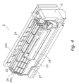
FIG. 4 is a diagram showing a state where a part in which a shield member and an added functional unit are integrated is attached to an indoor heat exchanger. -
FIG. 5 is a diagram showing the part in which the shield member and the added functional unit are integrated. -
- 1
- Air Conditioner
- 2
- Indoor Unit
- 20
- Indoor Heat Exchanger (Heat Exchanger)
- 21
- Cross-flow Fan (Blowing Component)
- 24
- Shield Member
- 25
- Added Functional Unit
- 29
- Coupling Member
- T
- Curved Portion
-
FIG. 1 shows the exterior of an air conditioner 1 in which an embodiment of the present invention is employed. - This air conditioner 1 is disposed with an
indoor unit 2 that is attached to an indoor wall surface or the likes and anoutdoor unit 3 that is installed outdoors. - An indoor heat exchanger 20 (heat exchanger) is housed inside the
indoor unit 2, an outdoor heat exchanger 30 (seeFIG. 2 ) is housed inside theoutdoor unit 3, and a refrigerant circuit is configured as a result of eath of the heat exchangers being interconnected by arefrigerant pipe 4. -
FIG. 2 shows the configuration of the refrigerant circuit of the air conditioner 1. This refrigerant circuit is mainly configured with theindoor heat exchanger 20, anaccumulator 31, acompressor 32, a four-way switch valve 33, theoutdoor heat exchanger 30 and an electricallypowered expansion valve 34. - The
indoor heat exchanger 20 disposed in theindoor unit 2 performs heat exchange with air coming into contact therewith. Further, a cross-flow fan 21 (blowing component) for sucking in indoor air and blowing out, into the indoors, air with respect to which heat exchange has been performed between that air and theindoor heat exchanger 20 is disposed in theindoor unit 2. Thecross-flow fan 21 is configured in a circular cylinder shape, with blades being disposed in an axis-of-rotation direction on the peripheral surface thereof, and generates an airflow in a direction intersecting the axis of rotation. Thiscross-flow fan 21 is driven to rotate by afan motor 22 disposed inside theindoor unit 2. The detailed configuration of the indoor unit will be described later. - Disposed in the
outdoor unit 3 are thecompressor 32, the four-way switch valve 33 that is connected to a discharge side of thecompressor 32, theaccumulator 31 that is connected to a suction side of thecompressor 32, theoutdoor heat exchanger 30 that is connected to the four-way switch valve 33, and the electricallypowered expansion valve 34 that is connected to theoutdoor heat exchanger 30. The electricallypowered expansion valve 34 is connected to apipe 41 via aliquid closing valve 36 and is connected to one end of theindoor heat exchanger 20 via thispipe 41. Further, the four-way switch valve 33 is connected to apipe 42 via agas closing valve 37 and is connected to the other end of theindoor heat exchanger 20 via thispipe 42. Thesepipes refrigerant pipe 4 inFIG. 1 . Further, apropeller fan 38 is disposed in theoutdoor unit 3 in order to discharge air to the outside after the air is being heat exchanged by theoutdoor heat exchanger 30. Thispropeller fan 38 is driven to rotate by afan motor 39. - As shown in
FIG. 1 , theindoor unit 2 is disposed with anindoor unit casing 23 that is long in a horizontal direction when seen from the front, and the aforementionedindoor heat exchanger 20 and thecross-flow fan 21 are housed inside the indoor unit casing 23 of theindoor unit 2. As described later, thisindoor heat exchanger 20 has a curved shape when seen from the side, and theindoor unit 2 is disposed with ashield member 24 that prevents air and water droplets from passing through a curved portion T of the indoor heat exchanger 20 (seeFIG. 3 to FIG. 5 ). Further, theindoor unit 2 is disposed with an added functional unit 25 (seeFIG. 3 to FIG. 5 ) that includes an air purifying function. As mentioned later, theshield member 24 and the addedfunctional unit 25 are integrated and attached to theindoor heat exchanger 20 as one part. -
FIG. 3 shows a side sectional view of theindoor unit 2. - The
indoor unit casing 23 is configured with afront panel 23a and abottom frame 23b. - The
front panel 23a is configured with atop face 230, abottom face 232, afront face 235, and side faces 236 and 237 (seeFIG. 1 ). Thetop face 230 covers the top of theindoor heat exchanger 20, and asuction opening 231 comprising plural slit-like openings is disposed in thetop face 230. Thebottom face 232 covers the bottom of theindoor heat exchanger 20 and thecross-flow fan 21, and ablowout opening 233 comprising an opening along a longitudinal direction of theindoor unit 2 is disposed in thebottom face 232. Further, ahorizontal flap 234 by which air to be blown out to the indoors is guided is disposed in theblowout opening 233. Thishorizontal flap 234 is disposed such that it may freely rotate about an axis parallel to the longitudinal direction of theindoor unit 2. Thehorizontal flap 234 is rotated by a flap motor (not shown) such that it can open and close theblowout opening 233. Thefront face 235 is generally formed flatly and covers the front of theindoor heat exchanger 20. The side faces 236 and 237 cover the sides of theindoor heat exchanger 20 as shown inFIG. 1 . The side faces 236 and 237 comprise aleft side face 236 and aright side face 237, with theleft side face 236 being disposed on the left side of theindoor heat exchanger 20 and the right side face being disposed on the right side of theindoor heat exchanger 20 when seen from the front. - The
bottom frame 23b configures the back face of theindoor unit 2 and covers the rear of theindoor heat exchanger 20. - Further, drain pans 238 for receiving water droplets generated on the surface of the indoor heat exchanger during heat exchange are disposed below the
indoor heat exchanger 20. A drain hose (not shown) for discharging the water droplets that the drain hose has received to the outside is attached to these drain pans 238. During cooling operation, theindoor heat exchanger 20 acts as an evaporation heat exchanger, so moisture included in the air that comes into contact with theindoor heat exchanger 20 condenses and drops as water droplets. The drain pans 238 are configured to receive such water droplets and discharge the water droplets by the drain hose. - The
indoor heat exchanger 20 is attached so as to surround the front, the top and the upper rear portion of thecross-flow fan 21. Theindoor heat exchanger 20 allows air that has been sucked in from thesuction opening 231 by the driving of thecross-flow fan 21 to pass therethrough towards thecross-flow fan 21 and causes heat exchange to be performed between the air and refrigerant passing through the insides ofheat exchange tubes 205. Theindoor heat exchanger 20 has a cross-sectional shape that is curved in a generally inverted "V" shape when seen from the side. - The
indoor heat exchanger 20 is divided into four portions comprising a firstindoor heat exchanger 20a, a secondindoor heat exchanger 20b, a thirdindoor heat exchanger 20c and a fourthindoor heat exchanger 20d. Each of the dividedindoor heat exchangers - The first
indoor heat exchanger 20a is disposed such that its upper end slants towards the front of theindoor unit 2, and is disposed so as to cover thecross-flow fan 21 from the top to the upper rear portion. The secondindoor heat exchanger 20b is disposed in front of the firstindoor heat exchanger 20a such that its upper end slants towards the rear of theindoor unit 2. The upper end of the secondindoor heat exchanger 20b is in proximity to the upper end of the firstindoor heat exchanger 20a. Because the upper end of the firstindoor heat exchanger 20a and the upper end of the secondindoor heat exchanger 20b are disposed in proximity to each other in this manner, a curved portion T of the inverted "V" shape is formed in the top portion of theindoor heat exchanger 20. The secondindoor heat exchanger 20b is disposed so as to cover the top of thecross-flow fan 21. The thirdindoor heat exchanger 20c is disposed below the secondindoor heat exchanger 20b, and the upper end of the thirdindoor heat exchanger 20c is in proximity to the lower end of the secondindoor heat exchanger 20b. The thirdindoor heat exchanger 20c is disposed so as to cover the front of thecross-flow fan 21. The fourthindoor heat exchanger 20d is disposed below the thirdindoor heat exchanger 20c such that its lower end slants towards the rear of theindoor unit 2. The upper end of the fourthindoor heat exchanger 20d is in proximity to the lower end of the thirdindoor heat exchanger 20c. - The first
indoor heat exchanger 20a, the secondindoor heat exchanger 20b, the thirdindoor heat exchanger 20c and the fourthindoor heat exchanger 20d are fixed to each other by metal side plates (not shown) disposed on both ends thereof (ends in the left-right direction when seen from the front), whereby they are integrated and form theindoor heat exchanger 20. - Each of the
indoor heat exchangers heat exchange tubes 205 that are folded back several times at both side ends andplural fins 206 through which theheat exchange tubes 205 are inserted. Theheat exchange tubes 205 are disposed in parallel in the longitudinal direction of each of theindoor heat exchangers indoor heat exchangers indoor heat exchanger 20 from both sides of each of theindoor heat exchangers - As shown in
FIG. 1 andFIG. 4 , thisindoor heat exchanger 20 is disposed towards the left side inside theindoor unit 2, and the left side end of theindoor heat exchanger 20 is in proximity to theleft side face 236 of theindoor unit casing 23. As shown inFIG. 4 , a fixingplate 26 that is made of a resin and in which plural holes are disposed is attached to the left side end of theindoor heat exchanger 20 and is configured so as to be integral with theindoor heat exchanger 20. It will be noted thatFIG. 4 shows a state where thefront panel 23a has been removed from theindoor unit 2. The U-shaped heat exchange tubes that project to the side from the left side end of theindoor heat exchanger 20 are passed through the holes in the fixingplate 26. This fixingplate 26 is fixed to thebottom frame 23b and fixes theindoor heat exchanger 20 to thebottom frame 23b. Further, the fixingplate 26 has a shape that projects frontward from the front of theindoor heat exchanger 20 and projects upward from the curved portion T in a state where the fixingplate 26 has been attached to theindoor heat exchanger 20. A hole for attaching a later-described addedfunctional unit 25 is disposed in a projectingportion 26a of this fixingplate 26. Further, the space between the right side end of theindoor heat exchanger 20 and theright side face 237 of theindoor unit casing 23 serves as a storage space for refrigerant pipes that are led inside theindoor unit 2 and connected to theindoor heat exchanger 20 and anelectrical parts box 10 that houses electrical parts. - As described above, the
indoor heat exchanger 20 is a unit in which theindoor heat exchangers plate 26 and configured to be integral, so gaps are present along the longitudinal direction between the divided surfaces of theindoor heat exchangers indoor heat exchanger 20a and the secondindoor heat exchanger 20b is positioned directly on the inside of thesuction opening 231 and between thesuction opening 231 and thecross-flow fan 21, so it becomes easy for air to pass therethrough. Additionally, air passing through this gap causes a drop in heat exchange effectiveness. For this reason, ashield member 24 that blocks this gap is attached to theindoor heat exchanger 20. - It will be noted that "left and right" in the above description means left and right when the
indoor unit 2 is seen from the front, and that "left and right" particularly relating to theindoor heat exchanger 20 means left and right when seen from the front in a state where theindoor heat exchanger 20 has been disposed in theindoor unit 2. Further, "left and right" relating to theshield member 24 that will be described below also means left and right when seen from the front in a state where theindoor heat exchanger 20 to which theshield member 24 has been attached has been disposed in theindoor unit 2. - The
shield member 24 is a member that is made of a resin and prevents air and water droplets from passing through the dividedindoor heat exchanger 20. As shown inFIG. 3 , theshield member 24 is attached so as to cover, from an upstream side, the gap at the curved portion T formed by the firstindoor heat exchanger 20a and the secondindoor heat exchanger 20b and covers and blocks the gap. - The
shield member 24 covers the gap from above along the curved portion T, so it has a substantially V-shaped cross-sectional shape that follows the shape of the curved portion T formed by the firstindoor heat exchanger 20a and the secondindoor heat exchanger 20b. The gap at this curved portion T is present along the longitudinal direction of theindoor heat exchanger 20, so as shown inFIG. 4 andFIG 5 , theshield member 24 also has a long and narrow shape of substantially the same length as the longitudinal direction length of theindoor heat exchanger 20. It will be noted that a lockingprotrusion 24a that projects towards the left side is disposed on the left side end portion of theshield member 24. This lockingprotrusion 24a is inserted into a hole disposed in the vicinity of the upper end of the fixingplate 26 for fixing theindoor heat exchanger 20, and theshield member 24 is locked to the fixingplate 26. - The added
functional unit 25 is an air purifying unit that includes an air purifying function and is disposed on the upstream side of theindoor heat exchanger 20. The addedfunctional unit 25 can purify air passing through theindoor heat exchanger 20 by creating a streamer discharge. As shown inFIG. 5 , the addedfunctional unit 25 includes anattachment member 27 and acover member 28. - The
attachment member 27 is a member that is made of a resin and has generally the same length as the longitudinal direction length of theindoor heat exchanger 20, and is disposed in proximity to the secondindoor heat exchanger 20b on the upstream side of the secondindoor heat exchanger 20b. Thecover member 28 is attached to the side of theattachment member 27 that is close to the electrical parts box 10 (the right side when seen from the front), and a discharging electrode and an opposing electrode for creating the streamer discharge and a filter and the like (not shown) are housed therein. The portion of theattachment member 27 where thecover member 28 is not disposed (the portion on the left side when seen from the front) is formed in a lattice and has a shape that sufficiently transmits air. Further, first fixingportions 27a and asecond fixing portion 27b are disposed respectively on both side ends of theattachment member 27. - The
first fixing portions 27a are plural protrusions that project from the left side end of theattachment member 27, are inserted into holes in the fixingplate 26, and theattachment member 27 is locked to the fixingplate 26. It will be noted that the holes in the fixingplate 26 are disposed so as to match the shape and placement of thefirst fixing portions 27a. - The
second fixing portion 27b is disposed in the vicinity of the right side end of theattachment member 27 and includes ascrew hole 27c that penetrates thesecond fixing portion 27b in the front-rear direction thereof. Thisscrew hole 27c in theattachment member 27 is disposed so as to coincide with a screw hole disposed in a side plate on the right side of theindoor heat exchanger 20, and screws are passed through these screw holes, whereby theattachment member 27 and the side plate are fixed to each other. It will be noted that a flange portion that is folded back in an almost right angle, for example, is disposed on the side plate on the right side of theindoor heat exchanger 20, and a screw hole that matches thescrew hole 27c in theattachment member 27 is disposed in this flange portion. By configuring in this manner, screws can be screwed from the front direction. It will be noted that astorage pocket 43 for storing a harness that interconnects the discharging electrode and the like and the electrical parts is disposed in the vicinity of the right side end of theattachment member 27. - Further, the
attachment member 27 is coupled to theshield member 24 byplural coupling members 29. Theplural coupling members 29 are arranged along the longitudinal direction of theindoor heat exchanger 20 and curve so as to follow the shape of theindoor heat exchanger 20. It will be noted that theattachment member 27, thecoupling members 29 and theshield member 24 are integrally molded by a resin. - In the
indoor unit 2 of this air conditioner 1, the addedfunctional unit 25 is attached as follows. - First, the added
functional unit 25 is disposed along the surface of the secondindoor heat exchanger 20b. Because the addedfunctional unit 25 is integrated with theshield member 24, theshield member 24 is disposed so as to cover the curved portion T at the same time that the addedfunctional unit 25 is disposed along the surface of the secondindoor heat exchanger 20b. Next, the addedfunctional unit 25 is moved in the left direction, and thefirst fixing portions 27a of the addedfunctional unit 25 are inserted into the holes in the fixingplate 26 from the right side of the fixingplate 26. It will be noted that, by this operation, the lockingprotrusion 24a of theshield member 24 is also inserted into a hole in the fixingplate 26. Additionally, the positions of thescrew hole 27c in thesecond fixing portion 27b and the screw hole in the side plate on the right side of theindoor heat exchanger 20 are fitted and fixed by a screw. Thus, the addedfunctional unit 25 and theshield member 24 are fixed to theindoor heat exchanger 20. - As described above, in the
indoor unit 2 of this air conditioner 1, the addedfunctional unit 25 is fixed to the side plate of theindoor heat exchanger 20 and the fixingplate 26, whereby theshield member 24 is fixedly attached to theindoor heat exchanger 20. For this reason, theshield member 24 can be easily attached to theindoor heat exchanger 20 without disposing, on theshield member 24, claw portions for press-fitting between the fins of theindoor heat exchanger 20. Further, the number of parts is reduced, and the addedfunctional unit 25 and theshield member 24 can be attached at once to theindoor heat exchanger 20 rather than being separately attached. Moreover, screwing for fixing suffices at one place. Thus, in theindoor unit 2 of this air conditioner 1, the assemblability of the parts is improved and productivity can be improved. - In the
indoor unit 2 of this air conditioner 1, the addedfunctional unit 25 and theshield member 24 are integrated by thecoupling members 29, and the addedfunctional unit 25, theshield member 24 and thecoupling members 29 are disposed along the shape of theindoor heat exchanger 20 because of the curved shape of thecoupling members 29. Thus, theindoor unit 2 can be configured compactly. Further, the addedfunctional unit 25 can be disposed in proximity to theindoor heat exchanger 20. - In an indoor unit of a conventional air conditioner where numerous claw portions have been disposed on the shield member, when the corners of the fins of the indoor heat exchanger are collapsed to form folded portions, it has been necessary to form the folded portions so as to avoid the positions where the claw portions of the shield member are press-fitted, which has been cumbersome.
- However, in the
indoor unit 2 of this air conditioner 1, the folded portions can be formed without considering the press-fitting positions of the claw portions, and the work of forming the folded portions is easy. - In the preceding embodiment, it is stated that it is not necessary to dispose claw portions on the
shield member 24, but a few claw portions may be disposed in order to prevent theshield member 24 from rising and shifting. In this case also, assemblability can be improved by relatively reducing the number of claw portions. - In the preceding embodiment, the added
functional unit 25 is fixed to the side plate that configures theindoor heat exchanger 20 and to the fixingplate 26 that is integrally fixed to theindoor heat exchanger 20, but the addedfunctional unit 25 may also be fixed to just the side plate. Further, the fixingplate 26 that is integrally fixed to theindoor heat exchanger 20 may also be disposed on both ends of the indoor heat exchanger, and the addedfunctional unit 25 may be fixed to just the fixingplates 26. That is, it suffices for the addedfunctional unit 25 to be fixedly disposed with respect to theindoor heat exchanger 20 regardless of whether it is directly or indirectly fixed. - In the preceding embodiment, the fixing of the added
functional unit 25 to the side plate that configures theindoor heat exchanger 20 is accomplished by a screw, and the fixing to the fixingplate 26 is accomplished by fitting in, but the fixing means are not limited to these and other fixing means may also be used. - In the preceding embodiment, the added
functional unit 25 is disposed on the front face of theindoor heat exchanger 20, but the addedfunctional unit 25 may also be disposed on the rear face of theindoor heat exchanger 20. - In the preceding embodiment, the added
functional unit 25 is an air purifying unit that includes an air purifying function performed by streamer discharge, but the addedfunctional unit 25 may also include an air purifying function performed by another principle. Examples of an air purifying function performed by another principle include a dust collecting function that collects dust by electrically charging dust passing therethrough. Further, an added functional unit for adding another function rather than an air purifying function may also be utilized. - In the preceding embodiment, the
indoor heat exchanger 20 is formed in a curved shape overall as a result of the divided pluralindoor heat exchangers 20a to 20d being assembled together, but theindoor heat exchanger 20 may also be formed in a curved shape as a result of an integrally formed heat exchanger undergoing bending or the like. - The present invention has the effect that it can improve productivity and is useful as an indoor unit of an air conditioner.
Claims (5)
- An indoor unit (2) of an air conditioner (1) comprising:a heat exchanger (20) that has a curved shape;a blowing component (21) that generates a flow of air that passes through the heat exchanger (20) and is blown out indoors;an added functional unit (25) that is disposed on an upstream side of the heat exchanger (20) and is fixed to the heat exchanger (20) or to a member that becomes integral with the heat exchanger (20); anda shield member (24) that is integrated with the added functional unit (25) and covers a curved portion (T) of the heat exchanger (20) from the upstream side.
- The indoor unit (2) of an air conditioner (1) of claim 1, wherein the added functional unit (25) is an air purifying unit that purifies the air that passes through the heat exchanger (20).
- The indoor unit (2) of an air conditioner (1) of either claim 1 or 2, wherein the shield member (24) is disposed on a top portion of the heat exchanger (20), and the added functional unit (25) is disposed on a front side or a rear side of the heat exchanger (20).
- The indoor unit (2) of an air conditioner (1) of claim 3, wherein the added functional unit (25) and the shield member (24) are integrated by a coupling member (29) that couples together the added functional unit (25) and the shield member (24).
- The indoor unit (2) of an air conditioner (1) of claim 4, wherein the coupling member (29) has a shape that is curved along the shape of the heat exchanger (20).
Applications Claiming Priority (2)
| Application Number | Priority Date | Filing Date | Title |
|---|---|---|---|
| JP2005317611A JP4010327B2 (en) | 2005-10-31 | 2005-10-31 | Air conditioner indoor unit |
| PCT/JP2006/321243 WO2007052509A1 (en) | 2005-10-31 | 2006-10-25 | Indoor machine of air conditioner |
Publications (2)
| Publication Number | Publication Date |
|---|---|
| EP1962026A1 true EP1962026A1 (en) | 2008-08-27 |
| EP1962026A4 EP1962026A4 (en) | 2011-05-25 |
Family
ID=38005660
Family Applications (1)
| Application Number | Title | Priority Date | Filing Date |
|---|---|---|---|
| EP06822220A Withdrawn EP1962026A4 (en) | 2005-10-31 | 2006-10-25 | INTERNAL MACHINE OF A CLIMATISEUR |
Country Status (3)
| Country | Link |
|---|---|
| EP (1) | EP1962026A4 (en) |
| JP (1) | JP4010327B2 (en) |
| WO (1) | WO2007052509A1 (en) |
Cited By (2)
| Publication number | Priority date | Publication date | Assignee | Title |
|---|---|---|---|---|
| US20130035028A1 (en) * | 2010-04-02 | 2013-02-07 | Gree Electric Appliances, Inc. Of Zhuhai | Indoor Unit of Air Conditioner |
| EP3012541A3 (en) * | 2014-07-31 | 2016-08-10 | Mitsubishi Heavy Industries, Ltd. | Air conditioner indoor unit |
Families Citing this family (2)
| Publication number | Priority date | Publication date | Assignee | Title |
|---|---|---|---|---|
| JP5142767B2 (en) * | 2008-03-07 | 2013-02-13 | 日立アプライアンス株式会社 | Air conditioner |
| JP5040866B2 (en) * | 2008-09-09 | 2012-10-03 | ダイキン工業株式会社 | air conditioner |
Family Cites Families (5)
| Publication number | Priority date | Publication date | Assignee | Title |
|---|---|---|---|---|
| JP3676547B2 (en) * | 1997-08-29 | 2005-07-27 | 東芝キヤリア株式会社 | Air conditioner |
| TW449654B (en) * | 1999-08-25 | 2001-08-11 | Fujitsu General Ltd | Air conditioner |
| JP2001248855A (en) * | 2000-03-06 | 2001-09-14 | Fujitsu General Ltd | Air conditioner |
| JP4333121B2 (en) * | 2002-11-08 | 2009-09-16 | ダイキン工業株式会社 | Air conditioner |
| JP4043387B2 (en) * | 2003-03-18 | 2008-02-06 | 三菱重工業株式会社 | Indoor unit for air conditioning and air conditioner equipped with the same |
-
2005
- 2005-10-31 JP JP2005317611A patent/JP4010327B2/en not_active Expired - Fee Related
-
2006
- 2006-10-25 EP EP06822220A patent/EP1962026A4/en not_active Withdrawn
- 2006-10-25 WO PCT/JP2006/321243 patent/WO2007052509A1/en not_active Ceased
Cited By (2)
| Publication number | Priority date | Publication date | Assignee | Title |
|---|---|---|---|---|
| US20130035028A1 (en) * | 2010-04-02 | 2013-02-07 | Gree Electric Appliances, Inc. Of Zhuhai | Indoor Unit of Air Conditioner |
| EP3012541A3 (en) * | 2014-07-31 | 2016-08-10 | Mitsubishi Heavy Industries, Ltd. | Air conditioner indoor unit |
Also Published As
| Publication number | Publication date |
|---|---|
| JP2007120928A (en) | 2007-05-17 |
| WO2007052509A1 (en) | 2007-05-10 |
| EP1962026A4 (en) | 2011-05-25 |
| JP4010327B2 (en) | 2007-11-21 |
Similar Documents
| Publication | Publication Date | Title |
|---|---|---|
| CN103557561B (en) | Air conditioning indoor unit embedded in ceiling | |
| US7998233B2 (en) | Air cleaner unit for vehicle and fan shroud having the same | |
| CN101375107B (en) | air conditioner | |
| CN106796038B (en) | Outdoor unit of air conditioner | |
| JPWO2019239630A1 (en) | Outdoor unit | |
| JP2002071157A (en) | Air conditioner | |
| CN102141275B (en) | Outdoor unit for air conditioner | |
| CN203595201U (en) | Outdoor unit of refrigeration plant | |
| JP2003074904A (en) | Electrical equipment and air conditioner | |
| JP4986696B2 (en) | Refrigeration air conditioner | |
| EP1677053A1 (en) | Outdoor unit of air conditioner | |
| JP3676547B2 (en) | Air conditioner | |
| JP4010327B2 (en) | Air conditioner indoor unit | |
| JP2005188831A (en) | Air conditioner indoor unit | |
| JP5101333B2 (en) | Air conditioner outdoor unit | |
| EP1780473A1 (en) | Air conditioner | |
| CN101268319B (en) | Side panel arrangement for evaporator units | |
| KR100732039B1 (en) | Indoor unit of air conditioner | |
| JP2011163564A (en) | Indoor unit of air conditioner | |
| CN100565022C (en) | The indoor unit of air-conditioning | |
| KR101198577B1 (en) | Open and close structure of outdoor air suction equipment | |
| JP5800740B2 (en) | Air conditioner indoor unit | |
| JP4857794B2 (en) | Air conditioner indoor unit | |
| JP4333121B2 (en) | Air conditioner | |
| JP2006349317A (en) | Assembling method of air conditioner and air conditioner |
Legal Events
| Date | Code | Title | Description |
|---|---|---|---|
| PUAI | Public reference made under article 153(3) epc to a published international application that has entered the european phase |
Free format text: ORIGINAL CODE: 0009012 |
|
| 17P | Request for examination filed |
Effective date: 20080527 |
|
| AK | Designated contracting states |
Kind code of ref document: A1 Designated state(s): AT BE BG CH CY CZ DE DK EE ES FI FR GB GR HU IE IS IT LI LT LU LV MC NL PL PT RO SE SI SK TR |
|
| A4 | Supplementary search report drawn up and despatched |
Effective date: 20110427 |
|
| STAA | Information on the status of an ep patent application or granted ep patent |
Free format text: STATUS: THE APPLICATION HAS BEEN WITHDRAWN |
|
| 18W | Application withdrawn |
Effective date: 20110706 |