EP1961892A2 - A shiftable wall for swimming pools - Google Patents
A shiftable wall for swimming pools Download PDFInfo
- Publication number
- EP1961892A2 EP1961892A2 EP08380049A EP08380049A EP1961892A2 EP 1961892 A2 EP1961892 A2 EP 1961892A2 EP 08380049 A EP08380049 A EP 08380049A EP 08380049 A EP08380049 A EP 08380049A EP 1961892 A2 EP1961892 A2 EP 1961892A2
- Authority
- EP
- European Patent Office
- Prior art keywords
- swimming pools
- wall
- shiftable wall
- shiftable
- per
- Prior art date
- Legal status (The legal status is an assumption and is not a legal conclusion. Google has not performed a legal analysis and makes no representation as to the accuracy of the status listed.)
- Withdrawn
Links
Images
Classifications
-
- E—FIXED CONSTRUCTIONS
- E04—BUILDING
- E04H—BUILDINGS OR LIKE STRUCTURES FOR PARTICULAR PURPOSES; SWIMMING OR SPLASH BATHS OR POOLS; MASTS; FENCING; TENTS OR CANOPIES, IN GENERAL
- E04H4/00—Swimming or splash baths or pools
- E04H4/14—Parts, details or accessories not otherwise provided for
- E04H4/145—Dividing means for swimming pools, e.g. panels, bulkheads
Definitions
- a shiftable wall for swimming pools is provided.
- a swimming pool will have to be of some given dimensions according to the use for which it is intended.
- the swimming pools for children are of more reduced dimensions as compared with those being intended for adults, said dimensions being bigger in the case of the competition swimming pools.
- a shiftable wall allowing to have them divided into two spaces of different dimensions.
- Said wall is shiftable along the length of the swimming pool and is made up by a bridge being arranged in a transversal arrangement and resting at its ends and by means of wheels on the lateral edges of the swimming pool, said lateral edges being provided with the corresponding rails.
- the shifting of the wall is obtained by linking each of its rolling ends to a respective hauling rope forming a guided loop and being driven by a motor.
- the ropes run along a pulley-guided path and have their ends linked to a drum having a helical periphery and being driven by the motor.
- the shiftable wall structure is made up by a framework comprising several lengths being joined together, the front and back faces of said framework being formed by grid panels.
- the wheels are of the double-wheel type and are divergently tapered at their periphery in correspondence with the tapers of the rail.
- the shiftable wall ends have been each provided with a respective resilient edge in order to thus have them properly adapted to the swimming pool vessel.
- the wall (1) being the object of this invention is a prefabricated wall and makes up a bridge (2) being arranged in a transversal arrangement in a swimming pool (3) and having at each of its ends a respective bearing (4) and (5) resting on the respective lateral edge (6) and (7) of the swimming pool.
- Two wheel pairs (8) and (9) ( Fig. 3 ) are fitted to each of these bearings and run on corresponding rails (10) ( Fig. 6 ), the wheels of each pair being divergently tapered at their periphery (11) in correspondence with the tapers (12) of the rails.
- the bridge (2) adapts at its ends to the swimming pool vessel by means of resilient edges (13) and the shiftable wall is made up by a framework (14) being formed by three lengths (a), (b) and (c) being joined together and at their front and back faces comprising grid panels (15) ( Fig. 4 ).
- the bridge ends being formed by the bearings (4) and (5) being provided with the wheel pairs (8) and (9) are each linked to a respective rope (16) and (17) ( Fig. 5 ) forming a respective loop being guided by pulleys (18), said ropes being driven by a motor (19) ( Fig. 7 ), the ropes being linked at their ends to a drum (20) having a helical periphery and being driven by the motor (19) through transmissions by means of sprockets and the corresponding sprocket chains (21), said drum being shifted on the screw spindle (22) and thus allowing the ropes to always be wound on the drum as per an arrangement being perpendicular to the axis of this latter.
- the motor unit will comprise means being such as to assure a synchronised shifting of the two ends of the bridge, this latter being provided with the proper safety devices that will deactivate the motor when the bridge during its shifting travel comes into juxtaposition to one of the ends walls of the swimming pool, or when there is an anomaly in its operation.
Abstract
Description
- A shiftable wall for swimming pools.
- As is known, a swimming pool will have to be of some given dimensions according to the use for which it is intended. For example the swimming pools for children are of more reduced dimensions as compared with those being intended for adults, said dimensions being bigger in the case of the competition swimming pools.
- Having several swimming pools with different dimensions represents a big space requirement and a high cost for building them.
- In order to solve this problem some swimming pools have been provided with a shiftable wall allowing to have them divided into two spaces of different dimensions. Said wall is shiftable along the length of the swimming pool and is made up by a bridge being arranged in a transversal arrangement and resting at its ends and by means of wheels on the lateral edges of the swimming pool, said lateral edges being provided with the corresponding rails.
- It is the object of this invention to improve this type of shiftable walls as regards both their make-up and their operation.
- For such a purpose the shifting of the wall is obtained by linking each of its rolling ends to a respective hauling rope forming a guided loop and being driven by a motor.
- The ropes run along a pulley-guided path and have their ends linked to a drum having a helical periphery and being driven by the motor.
- The shiftable wall structure is made up by a framework comprising several lengths being joined together, the front and back faces of said framework being formed by grid panels.
- The wheels are of the double-wheel type and are divergently tapered at their periphery in correspondence with the tapers of the rail.
- The shiftable wall ends have been each provided with a respective resilient edge in order to thus have them properly adapted to the swimming pool vessel.
- These and other characterising features will be best made apparent by the following detailed description whose understanding will be made easier by the accompanying two sheets of drawings showing a practical embodiment being cited only by way of example not limiting the scope of the present invention.
- In the drawings:
-
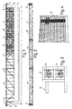
Fig. 1 illustrates in an elevational view the bridge making up the shiftable wall; -
Fig. 2 shows in a plan-view the framework of said shiftable wall; -
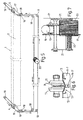
Fig. 3 shows in a plan-view one of the rolling ends of the bridge; -
Fig. 4 is a detail of the grid panels covering the front and back faces of the bridge framework; -
Fig. 5 diagrammatically depicts the loops of the ropes being used to drive the bridge; -
Fig. 6 is an elevational detail of the make-up of the wheels and the rail; and -
Fig. 7 shows in a plan-view the drum and motor unit being operable for driving the ropes. - According to the drawings the wall (1) being the object of this invention is a prefabricated wall and makes up a bridge (2) being arranged in a transversal arrangement in a swimming pool (3) and having at each of its ends a respective bearing (4) and (5) resting on the respective lateral edge (6) and (7) of the swimming pool.
- Two wheel pairs (8) and (9) (
Fig. 3 ) are fitted to each of these bearings and run on corresponding rails (10) (Fig. 6 ), the wheels of each pair being divergently tapered at their periphery (11) in correspondence with the tapers (12) of the rails. - The bridge (2) adapts at its ends to the swimming pool vessel by means of resilient edges (13) and the shiftable wall is made up by a framework (14) being formed by three lengths (a), (b) and (c) being joined together and at their front and back faces comprising grid panels (15) (
Fig. 4 ). - The bridge ends being formed by the bearings (4) and (5) being provided with the wheel pairs (8) and (9) are each linked to a respective rope (16) and (17) (
Fig. 5 ) forming a respective loop being guided by pulleys (18), said ropes being driven by a motor (19) (Fig. 7 ), the ropes being linked at their ends to a drum (20) having a helical periphery and being driven by the motor (19) through transmissions by means of sprockets and the corresponding sprocket chains (21), said drum being shifted on the screw spindle (22) and thus allowing the ropes to always be wound on the drum as per an arrangement being perpendicular to the axis of this latter. - The fact of the framework being made up of several lengths facilitates its transportation, said lengths being assembled together with no need for special machinery since they are joined together by means of screw fastening.
- The motor unit will comprise means being such as to assure a synchronised shifting of the two ends of the bridge, this latter being provided with the proper safety devices that will deactivate the motor when the bridge during its shifting travel comes into juxtaposition to one of the ends walls of the swimming pool, or when there is an anomaly in its operation.
- The invention can within its essentiality be put into practice in other embodiments only in detail differing from the one having been described above only by way of example, said other embodiments also falling within the scope of the protection being sought. This shiftable wall can hence be manufactured in any shape and size, with the best suited means and materials and with the most convenient accessories, and its integrating elements can be replaced with others being technically equivalent, all this falling within the spirit of the appended claims.
Claims (6)
- A shiftable wall for swimming pools which is made up by a transversal bridge (2) resting on the lateral edges (6 and 7) of the swimming pool (3) by means of wheels (8 and 9) running on rails (10) being provided at said edges (6 and 7), characterised in that the rolling ends of the bridge are each linked to a respective rope (16 and 17) forming a respective guided loop and being driven by a motor (19).
- A shiftable wall for swimming pools, as per claim 1, characterised in that the ropes (16 and 17) run along a path being guided by pulleys (18) and have their ends linked to a drum (20) having a helical periphery and being driven by the motor (19).
- A shiftable wall for swimming pools, as per claim 1, characterised in that it is made up by a framework (14) at its front and back faces comprising grid panels (15).
- A shiftable wall for swimming pools, as per claim 1, characterised in that the wheels (8 and 9) are of the double-wheel type and are divergently tapered at their periphery (11) in correspondence with the tapers (12) of the rails (10).
- A shiftable wall for swimming pools, as per claim 1, characterised in that its ends have been each provided with a respective resilient edge (13) in order to thus have them properly adapted to the vessel of the swimming pool (3).
- A shiftable wall for swimming pools, as per claim 3, characterised in that the framework (14) is made up by several lengths (a, b and c) being joined together.
Applications Claiming Priority (1)
| Application Number | Priority Date | Filing Date | Title |
|---|---|---|---|
| ES200700408U ES1064922Y (en) | 2007-02-23 | 2007-02-23 | WALL MOVABLE FOR POOLS |
Publications (2)
| Publication Number | Publication Date |
|---|---|
| EP1961892A2 true EP1961892A2 (en) | 2008-08-27 |
| EP1961892A3 EP1961892A3 (en) | 2011-04-27 |
Family
ID=38326704
Family Applications (1)
| Application Number | Title | Priority Date | Filing Date |
|---|---|---|---|
| EP08380049A Withdrawn EP1961892A3 (en) | 2007-02-23 | 2008-02-21 | A shiftable wall for swimming pools |
Country Status (2)
| Country | Link |
|---|---|
| EP (1) | EP1961892A3 (en) |
| ES (1) | ES1064922Y (en) |
Cited By (1)
| Publication number | Priority date | Publication date | Assignee | Title |
|---|---|---|---|---|
| WO2012062948A1 (en) * | 2010-11-08 | 2012-05-18 | Metalast, S.A. (Sociedad Unipersonal) | Movable support for the ends of the movable partition walls of swimming pools |
Citations (4)
| Publication number | Priority date | Publication date | Assignee | Title |
|---|---|---|---|---|
| US2754899A (en) * | 1954-06-29 | 1956-07-17 | Karobonik Jack | Safety cover for swimming pools |
| US3499174A (en) * | 1967-12-18 | 1970-03-10 | Thomas Francis Carey | Retractable swimming pool cover |
| US3501783A (en) * | 1967-10-24 | 1970-03-24 | Capitol Holding Corp | Swimming pool cover |
| EP1288396A1 (en) * | 2001-09-03 | 2003-03-05 | A & T Europe S.p.A. | Translation device for a mobile wall of a swimming pool |
-
2007
- 2007-02-23 ES ES200700408U patent/ES1064922Y/en not_active Expired - Fee Related
-
2008
- 2008-02-21 EP EP08380049A patent/EP1961892A3/en not_active Withdrawn
Patent Citations (4)
| Publication number | Priority date | Publication date | Assignee | Title |
|---|---|---|---|---|
| US2754899A (en) * | 1954-06-29 | 1956-07-17 | Karobonik Jack | Safety cover for swimming pools |
| US3501783A (en) * | 1967-10-24 | 1970-03-24 | Capitol Holding Corp | Swimming pool cover |
| US3499174A (en) * | 1967-12-18 | 1970-03-10 | Thomas Francis Carey | Retractable swimming pool cover |
| EP1288396A1 (en) * | 2001-09-03 | 2003-03-05 | A & T Europe S.p.A. | Translation device for a mobile wall of a swimming pool |
Cited By (3)
| Publication number | Priority date | Publication date | Assignee | Title |
|---|---|---|---|---|
| WO2012062948A1 (en) * | 2010-11-08 | 2012-05-18 | Metalast, S.A. (Sociedad Unipersonal) | Movable support for the ends of the movable partition walls of swimming pools |
| EP2639386A1 (en) * | 2010-11-08 | 2013-09-18 | Metalast, S.A. (Sociedad Unipersonal) | Movable support for the ends of the movable partition walls of swimming pools |
| EP2639386A4 (en) * | 2010-11-08 | 2014-09-10 | Metalast S A Soc Unipersonal | Movable support for the ends of the movable partition walls of swimming pools |
Also Published As
| Publication number | Publication date |
|---|---|
| ES1064922U (en) | 2007-05-16 |
| ES1064922Y (en) | 2007-08-16 |
| EP1961892A3 (en) | 2011-04-27 |
Similar Documents
| Publication | Publication Date | Title |
|---|---|---|
| US9227816B2 (en) | Vertical support structure and lifting device having the same | |
| JP2597077Y2 (en) | Synchronous drive belt and synchronous conduction pulley | |
| ES2344104T3 (en) | ELEVATOR WITH DRIVE DRIVE SYSTEM COMPOSED OF A BELT AND PULLEY. | |
| US6450317B1 (en) | Escalator drive machine | |
| EP1961892A2 (en) | A shiftable wall for swimming pools | |
| US1724713A (en) | Scaffolding | |
| DK30285D0 (en) | DRAWING FOR A HALL | |
| US10242597B2 (en) | Apparatus for moving vehicle crash test dummy and dummy testing apparatus | |
| JP2016166061A (en) | Extension member and passenger conveyor using the same | |
| AT511023B1 (en) | HANDRAIL FOR RIDING | |
| KR101733844B1 (en) | Belt Conveyor Carousel | |
| US3107773A (en) | Drive mechanism for an escalator | |
| JP5814146B2 (en) | Passenger conveyor | |
| CN206156550U (en) | Spiral automatic escalator | |
| US1772526A (en) | Amusement device for bathing pools | |
| EP2639386B1 (en) | Movable support for the ends of movable partition walls of swimming pools | |
| JP2017001826A (en) | Passenger conveyor | |
| CN107672680B (en) | A kind of cargo transport trolley of energy stair climbing | |
| JP2009007150A (en) | Chain conveyer apparatus | |
| CN215827801U (en) | Blocking mechanism based on VEX robot platform | |
| DE20204029U1 (en) | Escalator or moving walk | |
| AT515740B1 (en) | Mechanical compact garage system | |
| JP6077058B2 (en) | Passenger conveyor | |
| US516372A (en) | g-oebel | |
| DE202012007050U1 (en) | timing belts |
Legal Events
| Date | Code | Title | Description |
|---|---|---|---|
| PUAI | Public reference made under article 153(3) epc to a published international application that has entered the european phase |
Free format text: ORIGINAL CODE: 0009012 |
|
| AK | Designated contracting states |
Kind code of ref document: A2 Designated state(s): AT BE BG CH CY CZ DE DK EE ES FI FR GB GR HR HU IE IS IT LI LT LU LV MC MT NL NO PL PT RO SE SI SK TR |
|
| AX | Request for extension of the european patent |
Extension state: AL BA MK RS |
|
| PUAL | Search report despatched |
Free format text: ORIGINAL CODE: 0009013 |
|
| AK | Designated contracting states |
Kind code of ref document: A3 Designated state(s): AT BE BG CH CY CZ DE DK EE ES FI FR GB GR HR HU IE IS IT LI LT LU LV MC MT NL NO PL PT RO SE SI SK TR |
|
| AX | Request for extension of the european patent |
Extension state: AL BA MK RS |
|
| AKY | No designation fees paid | ||
| REG | Reference to a national code |
Ref country code: DE Ref legal event code: R108 |
|
| REG | Reference to a national code |
Ref country code: DE Ref legal event code: R108 Effective date: 20120104 |
|
| STAA | Information on the status of an ep patent application or granted ep patent |
Free format text: STATUS: THE APPLICATION IS DEEMED TO BE WITHDRAWN |
|
| 18D | Application deemed to be withdrawn |
Effective date: 20111028 |