EP1961858A1 - Laundry dryer - Google Patents
Laundry dryer Download PDFInfo
- Publication number
- EP1961858A1 EP1961858A1 EP07102792A EP07102792A EP1961858A1 EP 1961858 A1 EP1961858 A1 EP 1961858A1 EP 07102792 A EP07102792 A EP 07102792A EP 07102792 A EP07102792 A EP 07102792A EP 1961858 A1 EP1961858 A1 EP 1961858A1
- Authority
- EP
- European Patent Office
- Prior art keywords
- drum
- clothes
- electrode
- conductive contact
- contact member
- Prior art date
- Legal status (The legal status is an assumption and is not a legal conclusion. Google has not performed a legal analysis and makes no representation as to the accuracy of the status listed.)
- Granted
Links
- 238000001035 drying Methods 0.000 claims abstract description 26
- 239000002184 metal Substances 0.000 claims description 36
- 229910052751 metal Inorganic materials 0.000 claims description 36
- 239000012790 adhesive layer Substances 0.000 claims description 5
- 125000006850 spacer group Chemical group 0.000 claims description 5
- 238000010276 construction Methods 0.000 claims description 3
- 239000000463 material Substances 0.000 description 5
- 239000004033 plastic Substances 0.000 description 5
- 229920003023 plastic Polymers 0.000 description 5
- 230000000694 effects Effects 0.000 description 4
- 238000010292 electrical insulation Methods 0.000 description 4
- 239000012811 non-conductive material Substances 0.000 description 4
- 238000004891 communication Methods 0.000 description 2
- 239000003292 glue Substances 0.000 description 2
- 239000010410 layer Substances 0.000 description 2
- 238000005259 measurement Methods 0.000 description 2
- OKTJSMMVPCPJKN-UHFFFAOYSA-N Carbon Chemical compound [C] OKTJSMMVPCPJKN-UHFFFAOYSA-N 0.000 description 1
- RYGMFSIKBFXOCR-UHFFFAOYSA-N Copper Chemical compound [Cu] RYGMFSIKBFXOCR-UHFFFAOYSA-N 0.000 description 1
- 239000004743 Polypropylene Substances 0.000 description 1
- 238000010521 absorption reaction Methods 0.000 description 1
- 238000004026 adhesive bonding Methods 0.000 description 1
- 239000004020 conductor Substances 0.000 description 1
- 229910052802 copper Inorganic materials 0.000 description 1
- 239000010949 copper Substances 0.000 description 1
- 239000006260 foam Substances 0.000 description 1
- 229910002804 graphite Inorganic materials 0.000 description 1
- 239000010439 graphite Substances 0.000 description 1
- 238000010438 heat treatment Methods 0.000 description 1
- 239000012212 insulator Substances 0.000 description 1
- 239000002984 plastic foam Substances 0.000 description 1
- -1 polypropylene Polymers 0.000 description 1
- 229920001155 polypropylene Polymers 0.000 description 1
- 239000011347 resin Substances 0.000 description 1
- 229920005989 resin Polymers 0.000 description 1
- 230000000630 rising effect Effects 0.000 description 1
- 238000007789 sealing Methods 0.000 description 1
- 229910001220 stainless steel Inorganic materials 0.000 description 1
- 239000010935 stainless steel Substances 0.000 description 1
- 210000002105 tongue Anatomy 0.000 description 1
Images

Classifications
-
- D—TEXTILES; PAPER
- D06—TREATMENT OF TEXTILES OR THE LIKE; LAUNDERING; FLEXIBLE MATERIALS NOT OTHERWISE PROVIDED FOR
- D06F—LAUNDERING, DRYING, IRONING, PRESSING OR FOLDING TEXTILE ARTICLES
- D06F34/00—Details of control systems for washing machines, washer-dryers or laundry dryers
- D06F34/14—Arrangements for detecting or measuring specific parameters
- D06F34/18—Condition of the laundry, e.g. nature or weight
-
- D—TEXTILES; PAPER
- D06—TREATMENT OF TEXTILES OR THE LIKE; LAUNDERING; FLEXIBLE MATERIALS NOT OTHERWISE PROVIDED FOR
- D06F—LAUNDERING, DRYING, IRONING, PRESSING OR FOLDING TEXTILE ARTICLES
- D06F2101/00—User input for the control of domestic laundry washing machines, washer-dryers or laundry dryers
- D06F2101/16—Target humidity for the drying process, e.g. very-dry cycles
-
- D—TEXTILES; PAPER
- D06—TREATMENT OF TEXTILES OR THE LIKE; LAUNDERING; FLEXIBLE MATERIALS NOT OTHERWISE PROVIDED FOR
- D06F—LAUNDERING, DRYING, IRONING, PRESSING OR FOLDING TEXTILE ARTICLES
- D06F2103/00—Parameters monitored or detected for the control of domestic laundry washing machines, washer-dryers or laundry dryers
- D06F2103/02—Characteristics of laundry or load
- D06F2103/08—Humidity
- D06F2103/10—Humidity expressed as capacitance or resistance
-
- D—TEXTILES; PAPER
- D06—TREATMENT OF TEXTILES OR THE LIKE; LAUNDERING; FLEXIBLE MATERIALS NOT OTHERWISE PROVIDED FOR
- D06F—LAUNDERING, DRYING, IRONING, PRESSING OR FOLDING TEXTILE ARTICLES
- D06F2105/00—Systems or parameters controlled or affected by the control systems of washing machines, washer-dryers or laundry dryers
- D06F2105/62—Stopping or disabling machine operation
-
- D—TEXTILES; PAPER
- D06—TREATMENT OF TEXTILES OR THE LIKE; LAUNDERING; FLEXIBLE MATERIALS NOT OTHERWISE PROVIDED FOR
- D06F—LAUNDERING, DRYING, IRONING, PRESSING OR FOLDING TEXTILE ARTICLES
- D06F58/00—Domestic laundry dryers
- D06F58/32—Control of operations performed in domestic laundry dryers
- D06F58/34—Control of operations performed in domestic laundry dryers characterised by the purpose or target of the control
- D06F58/36—Control of operational steps, e.g. for optimisation or improvement of operational steps depending on the condition of the laundry
- D06F58/38—Control of operational steps, e.g. for optimisation or improvement of operational steps depending on the condition of the laundry of drying, e.g. to achieve the target humidity
-
- D—TEXTILES; PAPER
- D06—TREATMENT OF TEXTILES OR THE LIKE; LAUNDERING; FLEXIBLE MATERIALS NOT OTHERWISE PROVIDED FOR
- D06F—LAUNDERING, DRYING, IRONING, PRESSING OR FOLDING TEXTILE ARTICLES
- D06F58/00—Domestic laundry dryers
- D06F58/32—Control of operations performed in domestic laundry dryers
- D06F58/34—Control of operations performed in domestic laundry dryers characterised by the purpose or target of the control
- D06F58/52—Preventing or reducing noise
Definitions
- the present invention refers to a clothes drying machine.
- a laundry dryer In a laundry dryer, a very important feature is the ability to appropriately measure the degree of dryness of the clothes in order to adjust the duration of the drying cycle accordingly.
- a laundry dryer is generally provided with an electric circuit adapted to measure the residual moisture content in the clothes based on such parameter as the electric conductivity or resistance.
- Such circuit provided to carry out these moisture measurements generally comprises an electrically conductive contact strip supported on the metal annular wall of the dryer drum.
- the strip is electrically insulated from the drum by an electrically non-conductive pad bonded to the drum and interposed between the strip and the drum.
- the strip itself is electrically connected to electrodes, i.e. electric terminals, provided on the clothes rising ribs, or lifters, disposed on the metal inner surface of the annular wall of the drum.
- the electrodes are adapted to contact the laundry placed within the drum as it is tumbled during the rotation of the same drum, and they are suitably insulated from the metal inner surface of the drum annular wall by means of non-conductive elements.
- a scanning arm carrying a brush is mounted on the machine casing such that the brush is able to engage the conductive strip.
- the brush itself is electrically connected to a control unit, which is also electrically connected to the metal inner surface of the drum annular wall acting as the electric terminal of the circuit.
- the wet clothes inside the drum enable the electrodes on the drum clothes lifters to establish an electric communication with the metal inner surface of the drum, thereby closing, i.e. completing the circuit.
- the wet clothes connect the electric terminals of the circuit, i.e. the electrodes on the one side and the metal inner surface of the drum on the other side.
- this current can therefore flow through the wet clothes being dried, and a control unit in the machine can calculate the resistance and/or the conductivity of said clothes, thereby determining the appropriate duration of the drying cycle being performed.
- the clothes tumble within the drum they keep falling against the metal inner surface of drum, wherein heavier clothing items, as well as buttons, zippers and other metal or, anyway, hard ornaments that may be associated with the clothes being dried or hanging loose thereamong (e.g. coins) have a tendency to strike against the metal inner surface and generate noise in the course of the drying process.
- the metal drum works in this case as a resonant chamber, so that the level of the thus generated noise is eventually boosted.
- a need is therefore felt for the noise generated by clothes and other items tumbling within the dryer drum to be suitably reduced.
- both these sound-deadening solutions have the drawback of making the inner surface of the drum electrically non-conductive, since polymeric materials, as they are generally used to this purpose, are good electric insulators.
- the drying machine as generally indicated with the reference numeral 1, comprises a rotating drum 2 adapted to receive and hold clothes items 3 to be dried, one or more clothes lifters 4 provided on an inner annular surface 5 of the drum 2, and an electric circuit for determining the resistance and/or conductivity of the laundry contained in the rotating drum 2.
- Each clothes lifter 4 comprises at least a first electrode 6 and at least a second electrode 7 adapted to contact the laundry, wherein said electrodes are electrically insulated from each other.
- first conductive contact member 8 and a second conductive contact member 9 which extend round an external annular surface 10 of the drum 2 and are electrically connected to the first electrode 6 and to the second electrode 7, respectively; such conductive contact members 8, 9 are electrically insulated from each other.
- a first sliding contact 11 and a second sliding contact 12 are provided to slide along the first conductive contact member 8 and the second conductive contact member 9, respectively, under constant galvanic connection therewith when the drum 2 is rotating.
- a control unit 13 is electrically connected to both sliding contacts 11, 12 for measuring an electrical quantity depending on the residual moisture content in the laundry being tumbled in the drum and connecting said first and second electrodes 6, 7.
- the drying machine is provided with an outer casing adapted to allow the control panel of the machine to be mounted thereon, as well as a rotating drum 2 to be accommodated therein, along with motor and blower means.
- Such outer casing is provided with a door enabling the user to gain access to the interior of the drum through an access opening.
- the drum 2 is mounted inside this casing for rotation about the central axis thereof, as driven by a motor arranged to drive the drum 2.
- the drum 2 is also arranged so as to be included in an air flow-path, thereby enabling dry heated air to be forced therethrough to remove moisture from the clothes being tumbled therein.
- the drum 2 can comprise a side wall made of metal, in particular stainless steel, and lined inside with a sound-dampening layer in the form of an electrically non-conductive sheet, or it can comprise a side wall made of electrically non-conductive polymeric material, the latter embodiment being the one illustrated in the Figures accompanying this description.
- One or more clothes lifters 4 adapted to assist in appropriately tumbling the clothes being dried in the drum 2, are provided on the inner annular surface 5 of the drum side wall.
- the drum 2 can include a front flange 14 with a clothes-loading access opening and a rear flange 15 that is mechanically connected to a shaft about which the drum 2 is adapted to rotate.
- the flanges 14, 15 may be made both of metal and plastics and - possibly - in a single-piece unitary construction with the side wall of the drum.
- the drum can be comprised of a cylindrical side wall that is open at the front and rear ends thereof.
- the cylindrical side wall is rotatably fitted to a front support and a rear support to close the respective ends of the drum, while allowing the cylindrical side wall to rotate relative to the front and rear head members, which are stationary relative to the outer cabinet.
- Sealing members, fitted between the front support and the cylindrical side wall and the rear support and the cylindrical side wall, are provided for both allowing relative motion and preventing leakages.
- Each clothes lifter 4 comprises at least a first electrode 6 and at least a second electrode 7 that are electrically insulated from each other and adapted to contact the laundry placed within the drum 2 as it is tumbled during the rotation of the same drum 2.
- the first and the second electrode 6, 7 may for instance be provided in the form of a pair of metal surfaces that are electrically insulated from each other and associated externally to a support structure, which is advantageously made of an electrically non-conductive material, is applied to the inner annular surface 5 of the drum 2.
- the first electrode 6 of each clothes lifter 4 is electrically connected to the first electrically conductive contact member 8 consisting of a metal strip provided on the external annular surface 10 of the drum 2.
- first electrically conductive member 16 passing through a passage provided in the cylindrical wall of the drum 2 in correspondence to the portion of the drum 2 where the first electrode 6 of each clothes lifter 4 is situated.
- Such first electrically conductive member 16 protrudes from the cylindrical wall of the drum 2 in such manner as to bring about and establish the electric contact with the metal strip of the first electrically conductive contact member 8.
- the second electrode 7 of each clothes lifter 4 is electrically connected to the second conductive contact member 9, which is in turn formed of a metal strip provided on the external annular surface 10 of the drum 2.
- the connection itself is ensured by a second electrically conductive member 17 that passes through a further passage provided in the cylindrical wall of the drum 2 in correspondence to the portion of the drum 2 where the second electrode 7 of each clothes lifter 4 is situated.
- Such second electrically conductive member 17 protrudes from the cylindrical wall of the drum so as to contact the second electrically conductive contact member 9.
- the electrically conductive members 16, 17 passing through the wall of the drum are of course so positioned as to prevent them from being capable of coming into contact with each other, while ensuring an effective electrical insulation between the first and the second electrode 6, 7.
- first and second electrically conductive members 16, 17 are provided in a single-piece unitary construction, i.e. integral with the first and second electrodes 6, 7, respectively, and may for instance consist of metal tongues, or the like, arranged to pass through appropriate passages extending through the cylindrical wall of the drum 2 in correspondence to the positions where the clothes lifters 4 are situated.
- the drum 2 is made of an electrically non-conductive material, e.g. a polymeric plastic material, there is no need for the electrodes 6, 7 and the respective electrically conductive members 16, 17 to be electrically insulated from the drum 2, actually.
- an electrically non-conductive material e.g. a polymeric plastic material
- the electrodes 6, 7 are advantageously applied on to a support structure of the clothes lifters, which - further to ensuring proper electrical insulation between the first electrode 6 and the second electrode 7 - is also effective in electrically insulating the electrodes 6, 7 from the same drum 2. Insulating means are further provided between each electrically conductive member 16, 17 and the corresponding passageway through the wall of the drum, so as to electrically insulate each such electrically conductive member 16, 17 from the drum 2.
- each clothes lifter 4 is comprised of a first metal portion 6 and a second metal portion 7 acting as a first and a second electrode, respectively, which are applied to the inner annular surface 5 of the drum 2, as separated and electrically insulated from each other by a spacer member 18.
- each clothes lifter 4 is comprised of two metal halves 6, 7 that are separated from each other through the insulating spacer member 18. These two halves 6, 7 may be positioned in a side-by-side arrangement relative to each other along a direction extending parallel or perpendicular to the axis of rotation of the drum, with the spacer member 18 arranged between such two halves as illustrated in Figures 3 and 4 .
- insulating means are provided to electrically insulate the first and the second metal half 6, 7 of each clothes lifter 4 from the drum 2.
- use can be made of the sound-dampening sheet lining the inner annular surface 5 of the drum 2.
- further insulating means are provided to electrically insulate the electrically conductive members 16, 17 of each metal half 6, 7 of the clothes lifters from the side, i.e. annular metal wall of the drum 2 made of metal.
- the metal clothes lifters 4 are directly associated to the inner annular surface 5 of the drum 2, without any insulating means having to be interposed therebetween.
- both the metal strip of each conductive contact member 8, 9 and the related fastening means will of course be suitably insulated electrically from the drum 2 with the use of insulating means to be properly placed between the various electrically conductive bodies or members.
- electrically non-conductive members - usually made of rubber or plastics - are interposed between receptacles provided to extend through the wall of the drum and the fastening means due to be received therein, while a plastic band is positioned between the external annular surface of the drum 2 and the conductive contact member 8, 9 concerned.
- an adhesive layer of electrically insulating glue would be able to provide the required electrically insulating effect, without any need arising for further or additional insulating means to be interposed between the conductive contact members 8, 9 and the drum 2, actually.
- the clothes drying machine is also provided with a first sliding contact 11, which is adapted to slide on the first conductive contact member 8 in a constant galvanic connection therewith, and a second sliding contact 12, which is in turn adapted to slide on the second conductive contact member 9 in constant galvanic connection therewith, while the drum 2 is rotating.
- the sliding contacts 11, 12 are made of graphite, copper or a similar material, and each one of them is preferably provided in the form of a contact wiper, or brush, associated to the internal structure of the machine so as to maintain a stationary, i.e. fixed position relative to the same machine.
- a scanning arm 19 may for example be provided for carrying each such brush, i.e. each such sliding contact 11, 12.
- Each scanning arm 19 is mounted on the machine casing so as to be able to slidably engage the respective conductive contact members 8, 9 and enable the first and the second sliding contact 11, 12 to stay in a condition of electric contact constantly established with the first and the second conductive contact member 8, 9, respectively, while these members rotate jointly with the drum 2 during a drying cycle.
- Both sliding contacts 11, 12 are electrically connected with a control unit 13 to form an electric circuit adapted to determine the variation in the electric conductivity and/or the electric resistance of the clothes contained and being handled in the rotating drum 2 during a drying cycle.
- the above-cited electric circuit is therefore basically comprised of a first contact path including the first electrode 6 of each clothes lifter 4, the first conductive contact member 8 and the first sliding contact 11, and a second contact path including the second electrode 7 of each clothes lifter 4, the second conductive contact member 9 and the second sliding contact 12, wherein the control unit 13 connects the two contact paths with each other.
- the wet clothes inside the drum enable the first electrode 6 of each clothes lifter 4 to establish an electric communication with the second electrode 7 of each clothes lifter 4, thereby closing, i.e. completing the circuit.
- the control unit 13 is adapted to power the electric circuit so that an electric current is able to flow across the electric circuit and, as a result, also through the wet clothes residing in the drum. Since the resistance or the conductivity, as the case may be, of the electric circuit depends on the residual moisture content in the clothes being dried, the control unit 8 is able to continuously determine the degree of dryness reached by the laundry at each moment during the operation of the drying machine, so as to be in a position as to identify an end-of-cycle condition, at which the drying cycle is to be interrupted upon reaching the final degree of dryness selected by the user for the clothes being handled.
- the adhesive layer and the conductive contact members 8, 9 form a kind of sound-deadening lining that is particularly effective and advantageous in absorbing the sound waves generated by the clothes falling upon or colliding against the metal wall of the drum as the latter is rotating, especially when striking against such wall are some hard items generally associated to garment pieces, such as buttons or zippers.
- the sound waves that are generated by the pulse-like occurrences deriving from the clothes striking against the inner surface of the drum are for the most part absorbed by the adhesive layer which, by the effect of its viscoelastic properties, substantially converts these sound waves into heat, thereby heating up the adhesive layer.
- the conductive contact members 8, 9 are provided to cover most of the external annular surface 10 of the metallic drum 2, so as to be able to maximize the sound-wave absorption effect.
- the conductive contact members 8, 9 can be wrapped around the entire external annular surface of the drum 2, while of course ensuring due electrical insulation between the first and the second conductive contact member 8, 9.
- the clothes drying machine enables the electric conductivity and/or the electric resistance of the clothes being handled within the rotating drum to be determined, even when the inner surface of the drum adapted to come into contact with said clothes is made of an electrically non-conductive material.
Landscapes
- Engineering & Computer Science (AREA)
- Textile Engineering (AREA)
- Detail Structures Of Washing Machines And Dryers (AREA)
- Control Of Washing Machine And Dryer (AREA)
- Woven Fabrics (AREA)
- Polarising Elements (AREA)
- Crystals, And After-Treatments Of Crystals (AREA)
Abstract
Description
- The present invention refers to a clothes drying machine.
- In a laundry dryer, a very important feature is the ability to appropriately measure the degree of dryness of the clothes in order to adjust the duration of the drying cycle accordingly. To this purpose, a laundry dryer is generally provided with an electric circuit adapted to measure the residual moisture content in the clothes based on such parameter as the electric conductivity or resistance. Such circuit provided to carry out these moisture measurements generally comprises an electrically conductive contact strip supported on the metal annular wall of the dryer drum. The strip is electrically insulated from the drum by an electrically non-conductive pad bonded to the drum and interposed between the strip and the drum. On the other hand, the strip itself is electrically connected to electrodes, i.e. electric terminals, provided on the clothes rising ribs, or lifters, disposed on the metal inner surface of the annular wall of the drum.
- The electrodes are adapted to contact the laundry placed within the drum as it is tumbled during the rotation of the same drum, and they are suitably insulated from the metal inner surface of the drum annular wall by means of non-conductive elements.
- A scanning arm carrying a brush is mounted on the machine casing such that the brush is able to engage the conductive strip. The brush itself is electrically connected to a control unit, which is also electrically connected to the metal inner surface of the drum annular wall acting as the electric terminal of the circuit.
- The wet clothes inside the drum enable the electrodes on the drum clothes lifters to establish an electric communication with the metal inner surface of the drum, thereby closing, i.e. completing the circuit.
- In practice, the wet clothes connect the electric terminals of the circuit, i.e. the electrodes on the one side and the metal inner surface of the drum on the other side.
- When an electric current is supplied to the circuit, this current can therefore flow through the wet clothes being dried, and a control unit in the machine can calculate the resistance and/or the conductivity of said clothes, thereby determining the appropriate duration of the drying cycle being performed.
- As the clothes tumble within the drum, they keep falling against the metal inner surface of drum, wherein heavier clothing items, as well as buttons, zippers and other metal or, anyway, hard ornaments that may be associated with the clothes being dried or hanging loose thereamong (e.g. coins) have a tendency to strike against the metal inner surface and generate noise in the course of the drying process. Furthermore, the metal drum works in this case as a resonant chamber, so that the level of the thus generated noise is eventually boosted.
- A need is therefore felt for the noise generated by clothes and other items tumbling within the dryer drum to be suitably reduced.
- To compensate for or reduce the noise generated by the clothes and items being tumbled in the dryer drum, use is currently made of sheets of plastic foam, such as for instance polypropylene foam, to line the metal inner surface of the drum as a soundproofing means, or use is even made of a drum that is entirely made of such polymeric materials as resins or plastics that are inherently effective in dampening noise.
- However, both these sound-deadening solutions have the drawback of making the inner surface of the drum electrically non-conductive, since polymeric materials, as they are generally used to this purpose, are good electric insulators.
- It readily appears, therefore, that the afore-described electric circuit used to measure the residual moisture content of the clothes being dried would not be able to operate in this case, since the inner surface of the drum annular wall - owing to its being electrically non-conductive - cannot act as an electric terminal, i.e. is not in a position as to perform as an electric contact of the circuit to be connected - via the clothes - to the other electric terminals of the circuit, i.e. the electrodes provided on the clothes lifters inside the drum.
- It is therefore a main object of the present invention to provide a drying machine, which is effective in doing away with the above-noted drawbacks of the cited prior art.
- According to the present invention, this aim, along with further ones that will become apparent from the following disclosure, is reached in a drying machine that incorporates the features as defined and recited in the claims appended hereto.
- Features and advantages of the present invention will anyway be more readily understood from the description that is given below by way of nonlimiting example with reference to the accompanying drawings, in which:
-
Figure 1 is a front elevational, cross-sectional view of a drying machine according to the present invention; -
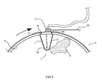
Figure 2 is an enlarged view of a detail ofFigure 1 ; -
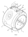
Figure 3 is a perspective view of the drum of the drying machine according to the present invention; -
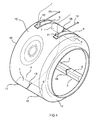
Figure 4 is a perspective view of the drum according to a second embodiment of the present invention. - With reference to the above-cited Figures, the drying machine, as generally indicated with the
reference numeral 1, comprises a rotatingdrum 2 adapted to receive and holdclothes items 3 to be dried, one ormore clothes lifters 4 provided on an innerannular surface 5 of thedrum 2, and an electric circuit for determining the resistance and/or conductivity of the laundry contained in the rotatingdrum 2. - Each
clothes lifter 4 comprises at least afirst electrode 6 and at least asecond electrode 7 adapted to contact the laundry, wherein said electrodes are electrically insulated from each other. - There are provided a first
conductive contact member 8 and a secondconductive contact member 9, which extend round an externalannular surface 10 of thedrum 2 and are electrically connected to thefirst electrode 6 and to thesecond electrode 7, respectively; suchconductive contact members - A first sliding
contact 11 and a second slidingcontact 12 are provided to slide along the firstconductive contact member 8 and the secondconductive contact member 9, respectively, under constant galvanic connection therewith when thedrum 2 is rotating. - A
control unit 13 is electrically connected to both slidingcontacts second electrodes - The drying machine is provided with an outer casing adapted to allow the control panel of the machine to be mounted thereon, as well as a rotating
drum 2 to be accommodated therein, along with motor and blower means. - Such outer casing is provided with a door enabling the user to gain access to the interior of the drum through an access opening. The
drum 2 is mounted inside this casing for rotation about the central axis thereof, as driven by a motor arranged to drive thedrum 2. - Within said outer casing, the
drum 2 is also arranged so as to be included in an air flow-path, thereby enabling dry heated air to be forced therethrough to remove moisture from the clothes being tumbled therein. - The
drum 2 can comprise a side wall made of metal, in particular stainless steel, and lined inside with a sound-dampening layer in the form of an electrically non-conductive sheet, or it can comprise a side wall made of electrically non-conductive polymeric material, the latter embodiment being the one illustrated in the Figures accompanying this description. - One or
more clothes lifters 4, adapted to assist in appropriately tumbling the clothes being dried in thedrum 2, are provided on the innerannular surface 5 of the drum side wall. - The
drum 2 can include afront flange 14 with a clothes-loading access opening and arear flange 15 that is mechanically connected to a shaft about which thedrum 2 is adapted to rotate. Theflanges - In an alternative embodiment, the drum can be comprised of a cylindrical side wall that is open at the front and rear ends thereof. The cylindrical side wall is rotatably fitted to a front support and a rear support to close the respective ends of the drum, while allowing the cylindrical side wall to rotate relative to the front and rear head members, which are stationary relative to the outer cabinet. Sealing members, fitted between the front support and the cylindrical side wall and the rear support and the cylindrical side wall, are provided for both allowing relative motion and preventing leakages.
- Each
clothes lifter 4 comprises at least afirst electrode 6 and at least asecond electrode 7 that are electrically insulated from each other and adapted to contact the laundry placed within thedrum 2 as it is tumbled during the rotation of thesame drum 2. The first and thesecond electrode annular surface 5 of thedrum 2. - It will of course be most readily appreciated that the greater is the extension of such surfaces, the greater will be the ability thereof to come into contact with the clothes being dried and, hence, the greater will be the accuracy in the measurement of the conductivity of the same clothes, in particular when such clothes have already reached a relatively advanced stage of the drying process, i.e. are already in a near-dry condition, or when the laundry load in the drum is a relatively small one.
- The
first electrode 6 of eachclothes lifter 4 is electrically connected to the first electricallyconductive contact member 8 consisting of a metal strip provided on the externalannular surface 10 of thedrum 2. For such electrical connection there is provided a first electricallyconductive member 16 passing through a passage provided in the cylindrical wall of thedrum 2 in correspondence to the portion of thedrum 2 where thefirst electrode 6 of eachclothes lifter 4 is situated. Such first electricallyconductive member 16 protrudes from the cylindrical wall of thedrum 2 in such manner as to bring about and establish the electric contact with the metal strip of the first electricallyconductive contact member 8. - In a fully similar manner, the
second electrode 7 of eachclothes lifter 4 is electrically connected to the secondconductive contact member 9, which is in turn formed of a metal strip provided on the externalannular surface 10 of thedrum 2. The connection itself is ensured by a second electricallyconductive member 17 that passes through a further passage provided in the cylindrical wall of thedrum 2 in correspondence to the portion of thedrum 2 where thesecond electrode 7 of eachclothes lifter 4 is situated. Such second electricallyconductive member 17 protrudes from the cylindrical wall of the drum so as to contact the second electricallyconductive contact member 9. - The electrically
conductive members second electrode - Advantageously, the first and second electrically
conductive members second electrodes drum 2 in correspondence to the positions where theclothes lifters 4 are situated. - In the case that the
drum 2 is made of an electrically non-conductive material, e.g. a polymeric plastic material, there is no need for theelectrodes conductive members drum 2, actually. - In the case that the
drum 2 is on the contrary made of metal, theelectrodes first electrode 6 and the second electrode 7 - is also effective in electrically insulating theelectrodes same drum 2. Insulating means are further provided between each electricallyconductive member conductive member drum 2. - In a preferred embodiment of the present invention, each
clothes lifter 4 is comprised of afirst metal portion 6 and asecond metal portion 7 acting as a first and a second electrode, respectively, which are applied to the innerannular surface 5 of thedrum 2, as separated and electrically insulated from each other by aspacer member 18. In an advantageous manner, eachclothes lifter 4 is comprised of twometal halves insulating spacer member 18. These twohalves spacer member 18 arranged between such two halves as illustrated inFigures 3 and4 . - In the case that the
drum 2 is made of metal, insulating means are provided to electrically insulate the first and thesecond metal half clothes lifter 4 from thedrum 2. To such purpose, use can be made of the sound-dampening sheet lining the innerannular surface 5 of thedrum 2. In addition, further insulating means are provided to electrically insulate the electricallyconductive members metal half drum 2 made of metal. - It can of course be readily appreciated that, when the
drum 2 is entirely made of an electrically non-conductive material, themetal clothes lifters 4 are directly associated to the innerannular surface 5 of thedrum 2, without any insulating means having to be interposed therebetween. - Each
conductive contact members annular surface 10 of thedrum 2 with the help of appropriate fastening means or by adhesive bonding. - If the
drum 2 is made of an electrically conductive material, both the metal strip of eachconductive contact member drum 2 with the use of insulating means to be properly placed between the various electrically conductive bodies or members. - For example, in view of ensuring the required electrical insulation between the
drum 2 and theconductive contact members drum 2 and theconductive contact member - On the other hand, an adhesive layer of electrically insulating glue would be able to provide the required electrically insulating effect, without any need arising for further or additional insulating means to be interposed between the
conductive contact members drum 2, actually. - All this is further effective in ensuring that the first
conductive contact member 8 and the secondconductive contact member 9 are electrically insulated also from each other. - In addition, according to the present invention the clothes drying machine is also provided with a first sliding
contact 11, which is adapted to slide on the firstconductive contact member 8 in a constant galvanic connection therewith, and a second slidingcontact 12, which is in turn adapted to slide on the secondconductive contact member 9 in constant galvanic connection therewith, while thedrum 2 is rotating. - The sliding
contacts scanning arm 19 may for example be provided for carrying each such brush, i.e. each such slidingcontact - Each
scanning arm 19 is mounted on the machine casing so as to be able to slidably engage the respectiveconductive contact members contact conductive contact member drum 2 during a drying cycle. - Both sliding
contacts control unit 13 to form an electric circuit adapted to determine the variation in the electric conductivity and/or the electric resistance of the clothes contained and being handled in therotating drum 2 during a drying cycle. - The above-cited electric circuit is therefore basically comprised of a first contact path including the
first electrode 6 of each clothes lifter 4, the firstconductive contact member 8 and the first slidingcontact 11, and a second contact path including thesecond electrode 7 of each clothes lifter 4, the secondconductive contact member 9 and the second slidingcontact 12, wherein thecontrol unit 13 connects the two contact paths with each other. - The wet clothes inside the drum enable the
first electrode 6 of each clothes lifter 4 to establish an electric communication with thesecond electrode 7 of each clothes lifter 4, thereby closing, i.e. completing the circuit. - The
control unit 13 is adapted to power the electric circuit so that an electric current is able to flow across the electric circuit and, as a result, also through the wet clothes residing in the drum. Since the resistance or the conductivity, as the case may be, of the electric circuit depends on the residual moisture content in the clothes being dried, thecontrol unit 8 is able to continuously determine the degree of dryness reached by the laundry at each moment during the operation of the drying machine, so as to be in a position as to identify an end-of-cycle condition, at which the drying cycle is to be interrupted upon reaching the final degree of dryness selected by the user for the clothes being handled. - It should further be noticed that the adhesive layer and the
conductive contact members - This is of particular advantage in the case that the drum is made of metal, since it would contribute to boosting the noise-dampening effect generally ensured by the non-conductive sound-deadening sheet lining the inner metal surface of the drum.
- The sound waves that are generated by the pulse-like occurrences deriving from the clothes striking against the inner surface of the drum are for the most part absorbed by the adhesive layer which, by the effect of its viscoelastic properties, substantially converts these sound waves into heat, thereby heating up the adhesive layer.
- On the other hand, the sound waves that succeed in passing through and issuing from the glue layer are transmitted to the
conductive contact members - In a particularly advantageous embodiment of the present invention, the
conductive contact members annular surface 10 of themetallic drum 2, so as to be able to maximize the sound-wave absorption effect. In practice, theconductive contact members drum 2, while of course ensuring due electrical insulation between the first and the secondconductive contact member - Conclusively, it can therefore be stated that the clothes drying machine according to the present invention enables the electric conductivity and/or the electric resistance of the clothes being handled within the rotating drum to be determined, even when the inner surface of the drum adapted to come into contact with said clothes is made of an electrically non-conductive material.
Claims (8)
- Clothes drying machine comprising a rotating drum (2) adapted to receive laundry items (3) to be dried, one or more clothes lifters (4) provided on an inner annular surface (5) of the drum (2), and an electric circuit for determining the electrical resistance and/or conductivity of the laundry contained in the rotating drum (2), characterized in that each clothes lifter (4) comprises at least a first electrode (6) and at least a second electrode (7) adapted to contact the laundry and electrically insulated from each other, a first conductive contact member (8) and a second conductive contact member (9), extending all along an external annular surface (10) of the drum (2), are electrically connected to the first electrode (6) and to the second electrode (7), respectively, said conductive contact members (8, 9) being electrically insulated from each other, a first sliding contact (11) and a second sliding contact (12) are adapted to slide along the first conductive contact member (8) and the second conductive contact member (9), respectively, in constant galvanic connection therewith when the drum (2) is rotating, and a control unit (13) is electrically connected to both sliding contacts (11,12) for measuring an electrical quantity depending on the residual moisture content in the laundry being dried and connecting said first and second electrodes (6, 7).
- Clothes drying machine according to claim 1, wherein each clothes lifter (4) comprises a first metal portion that acts as the first electrode (6), and a second metal portion that acts as the second electrode (7), such portions being applied to the inner annular surface (5) of the drum (2) and electrically insulated from each other by an insulating spacer member (18).
- Clothes drying machine according to claim 2, wherein each clothes lifter (4) is comprised of two metal halves that are separated from each other by said insulating spacer member (18).
- Clothes drying machine according to any of the preceding claims, wherein a first electrically conductive member (16) extends through the wall of the drum (2) to electrically connect said first electrode (6) of each clothes lifter (4) with said first conductive contact member (8).
- Clothes drying machine according to any of the preceding claims, wherein a second electrically conductive member (17) extends through the wall of the drum (2) to electrically connect said second electrode (7) of each clothes lifter (4) with said second conductive contact member (9).
- Clothes drying machine according to claims 4 and 5, wherein said first and second electrically conductive members (16, 17) are provided in the form of a single-piece unitary construction with the first and the second electrode (6, 7), respectively.
- Clothes drying machine according to any of the preceding claims, wherein said electric circuit comprises a first contact path including the first electrode (6) of each clothes lifter (4), the first conductive contact member (8) and the first sliding contact (11), and a second contact path including the second electrode (7) of each clothes lifter (4), the second conductive contact member (9) and the second sliding contact (12), wherein the control unit (13) connects the two contact paths with each other.
- Clothes drying machine according to any of the preceding claims, wherein each conductive contact member (8, 9) is attached to the external annular surface (10) of the drum (2) by means of an adhesive layer.
Priority Applications (6)
| Application Number | Priority Date | Filing Date | Title |
|---|---|---|---|
| PL07102792T PL1961858T3 (en) | 2007-02-21 | 2007-02-21 | Laundry dryer |
| ES07102792T ES2360250T3 (en) | 2007-02-21 | 2007-02-21 | COLADA DRYER. |
| DE602007012048T DE602007012048D1 (en) | 2007-02-21 | 2007-02-21 | clothes dryer |
| AT07102792T ATE496164T1 (en) | 2007-02-21 | 2007-02-21 | CLOTH DRYER |
| EP07102792A EP1961858B1 (en) | 2007-02-21 | 2007-02-21 | Laundry dryer |
| RU2008106637/12A RU2466229C2 (en) | 2007-02-21 | 2008-02-20 | Dryer for laundry |
Applications Claiming Priority (1)
| Application Number | Priority Date | Filing Date | Title |
|---|---|---|---|
| EP07102792A EP1961858B1 (en) | 2007-02-21 | 2007-02-21 | Laundry dryer |
Publications (2)
| Publication Number | Publication Date |
|---|---|
| EP1961858A1 true EP1961858A1 (en) | 2008-08-27 |
| EP1961858B1 EP1961858B1 (en) | 2011-01-19 |
Family
ID=38235363
Family Applications (1)
| Application Number | Title | Priority Date | Filing Date |
|---|---|---|---|
| EP07102792A Not-in-force EP1961858B1 (en) | 2007-02-21 | 2007-02-21 | Laundry dryer |
Country Status (6)
| Country | Link |
|---|---|
| EP (1) | EP1961858B1 (en) |
| AT (1) | ATE496164T1 (en) |
| DE (1) | DE602007012048D1 (en) |
| ES (1) | ES2360250T3 (en) |
| PL (1) | PL1961858T3 (en) |
| RU (1) | RU2466229C2 (en) |
Cited By (9)
| Publication number | Priority date | Publication date | Assignee | Title |
|---|---|---|---|---|
| US20120291302A1 (en) * | 2011-05-16 | 2012-11-22 | Bsh Home Appliances Corporation | Noise-reducing laundry drum for a household appliance |
| WO2013182402A1 (en) | 2012-06-06 | 2013-12-12 | Arcelik Anonim Sirketi | Laundry washing/drying machine |
| WO2019132809A1 (en) * | 2017-12-25 | 2019-07-04 | Arcelik Anonim Sirketi | A device detecting dryness of laundry |
| CN112086301A (en) * | 2020-09-19 | 2020-12-15 | 杨光华 | Capacitor drying device capable of lifting and discharging |
| CN118007388A (en) * | 2024-02-04 | 2024-05-10 | 珠海格力电器股份有限公司 | Clothes processing device and control method |
| CN118007387A (en) * | 2024-02-04 | 2024-05-10 | 珠海格力电器股份有限公司 | Clothes treatment equipment |
| CN118029096A (en) * | 2024-02-04 | 2024-05-14 | 珠海格力电器股份有限公司 | Clothes processing equipment |
| CN119980668A (en) * | 2025-01-24 | 2025-05-13 | 珠海格力电器股份有限公司 | Dryness determination method, drying method and clothing treatment equipment |
| WO2026051451A1 (en) * | 2024-09-03 | 2026-03-12 | 无锡美芝电器有限公司 | Lifter assembly and laundry treatment device |
Families Citing this family (1)
| Publication number | Priority date | Publication date | Assignee | Title |
|---|---|---|---|---|
| TR2024011594A2 (en) | 2024-09-03 | 2026-03-23 | Arçeli̇k Anoni̇m Şi̇rketi̇ | A HOUSEHOLD APPLIANCE THAT PROVIDES EFFECTIVE DRYING AND A METHOD FOR ITS CONTROL. |
Citations (3)
| Publication number | Priority date | Publication date | Assignee | Title |
|---|---|---|---|---|
| US3603805A (en) * | 1968-07-11 | 1971-09-07 | Holzer Patent Ag | Device for controlling laundry driers with mechanical movement of the washing, in dependence upon the degree of drying |
| JPS6214900A (en) * | 1985-07-12 | 1987-01-23 | 株式会社東芝 | Operation controller of dryer |
| KR20040049186A (en) * | 2002-12-05 | 2004-06-11 | 엘지전자 주식회사 | device for detecting dryness and method for controlling clothes dryer |
Family Cites Families (2)
| Publication number | Priority date | Publication date | Assignee | Title |
|---|---|---|---|---|
| GB2068099B (en) * | 1980-01-28 | 1983-07-06 | Philips Electronic Associated | Control device for laundry drier |
| DE19522432A1 (en) * | 1995-06-21 | 1997-01-02 | Miele & Cie | Laundry dryer with reduced cost and simplified assembly |
-
2007
- 2007-02-21 ES ES07102792T patent/ES2360250T3/en active Active
- 2007-02-21 DE DE602007012048T patent/DE602007012048D1/en active Active
- 2007-02-21 AT AT07102792T patent/ATE496164T1/en not_active IP Right Cessation
- 2007-02-21 EP EP07102792A patent/EP1961858B1/en not_active Not-in-force
- 2007-02-21 PL PL07102792T patent/PL1961858T3/en unknown
-
2008
- 2008-02-20 RU RU2008106637/12A patent/RU2466229C2/en not_active IP Right Cessation
Patent Citations (3)
| Publication number | Priority date | Publication date | Assignee | Title |
|---|---|---|---|---|
| US3603805A (en) * | 1968-07-11 | 1971-09-07 | Holzer Patent Ag | Device for controlling laundry driers with mechanical movement of the washing, in dependence upon the degree of drying |
| JPS6214900A (en) * | 1985-07-12 | 1987-01-23 | 株式会社東芝 | Operation controller of dryer |
| KR20040049186A (en) * | 2002-12-05 | 2004-06-11 | 엘지전자 주식회사 | device for detecting dryness and method for controlling clothes dryer |
Cited By (10)
| Publication number | Priority date | Publication date | Assignee | Title |
|---|---|---|---|---|
| US20120291302A1 (en) * | 2011-05-16 | 2012-11-22 | Bsh Home Appliances Corporation | Noise-reducing laundry drum for a household appliance |
| WO2013182402A1 (en) | 2012-06-06 | 2013-12-12 | Arcelik Anonim Sirketi | Laundry washing/drying machine |
| WO2019132809A1 (en) * | 2017-12-25 | 2019-07-04 | Arcelik Anonim Sirketi | A device detecting dryness of laundry |
| CN112086301A (en) * | 2020-09-19 | 2020-12-15 | 杨光华 | Capacitor drying device capable of lifting and discharging |
| CN118007388A (en) * | 2024-02-04 | 2024-05-10 | 珠海格力电器股份有限公司 | Clothes processing device and control method |
| CN118007387A (en) * | 2024-02-04 | 2024-05-10 | 珠海格力电器股份有限公司 | Clothes treatment equipment |
| CN118029096A (en) * | 2024-02-04 | 2024-05-14 | 珠海格力电器股份有限公司 | Clothes processing equipment |
| CN118007388B (en) * | 2024-02-04 | 2026-01-16 | 珠海格力电器股份有限公司 | Clothes treatment equipment and control method |
| WO2026051451A1 (en) * | 2024-09-03 | 2026-03-12 | 无锡美芝电器有限公司 | Lifter assembly and laundry treatment device |
| CN119980668A (en) * | 2025-01-24 | 2025-05-13 | 珠海格力电器股份有限公司 | Dryness determination method, drying method and clothing treatment equipment |
Also Published As
| Publication number | Publication date |
|---|---|
| ATE496164T1 (en) | 2011-02-15 |
| PL1961858T3 (en) | 2011-06-30 |
| ES2360250T3 (en) | 2011-06-02 |
| EP1961858B1 (en) | 2011-01-19 |
| RU2466229C2 (en) | 2012-11-10 |
| DE602007012048D1 (en) | 2011-03-03 |
| RU2008106637A (en) | 2009-08-27 |
Similar Documents
| Publication | Publication Date | Title |
|---|---|---|
| EP1961858B1 (en) | Laundry dryer | |
| US9758920B2 (en) | Clothes treating apparatus with detecting device for insertion of filter | |
| RU2453643C2 (en) | Machine for drying clothes | |
| CN108138432B (en) | Laundry appliance with capacitive laundry dryness sensing function | |
| EP1988209B1 (en) | Method of controlling a tumble laundry drier | |
| CN219908191U (en) | Clothes treating apparatus | |
| KR101186597B1 (en) | Exausting Type of Dryer | |
| EP1914341B1 (en) | Drying machine | |
| CN103080411B (en) | Method for operating a clothes drying appliance and clothes drying appliance | |
| US11920272B2 (en) | Appliance with capacitive humidity sensor | |
| KR20050095434A (en) | Clothing dryer | |
| CN219908188U (en) | Clothes treating apparatus | |
| KR20040049186A (en) | device for detecting dryness and method for controlling clothes dryer | |
| US7043944B2 (en) | Drum type washing and drying apparatus | |
| KR20030041428A (en) | cloth dryer | |
| EP2126188A1 (en) | A washer / dryer with output from humidity sensor selectively input to control unit | |
| CN220224686U (en) | Drying equipment | |
| JP2013128637A (en) | Drum type dryer | |
| EP2377989A1 (en) | Method of assembling the drum of a laundry drier and drum for laundry driers | |
| CN1854381B (en) | A new type of dryer | |
| KR20070063997A (en) | Drying Machine of Drum Washing Machine | |
| EP1449954B1 (en) | Low-noise household clothes drying machine | |
| WO2007077113A1 (en) | A washer/ dryer | |
| CN222349350U (en) | Clothes treatment equipment with drying function | |
| KR200264786Y1 (en) | cloth dryer |
Legal Events
| Date | Code | Title | Description |
|---|---|---|---|
| PUAI | Public reference made under article 153(3) epc to a published international application that has entered the european phase |
Free format text: ORIGINAL CODE: 0009012 |
|
| AK | Designated contracting states |
Kind code of ref document: A1 Designated state(s): AT BE BG CH CY CZ DE DK EE ES FI FR GB GR HU IE IS IT LI LT LU LV MC NL PL PT RO SE SI SK TR |
|
| AX | Request for extension of the european patent |
Extension state: AL BA HR MK RS |
|
| 17P | Request for examination filed |
Effective date: 20081222 |
|
| 17Q | First examination report despatched |
Effective date: 20090318 |
|
| AKX | Designation fees paid |
Designated state(s): AT BE BG CH CY CZ DE DK EE ES FI FR GB GR HU IE IS IT LI LT LU LV MC NL PL PT RO SE SI SK TR |
|
| GRAP | Despatch of communication of intention to grant a patent |
Free format text: ORIGINAL CODE: EPIDOSNIGR1 |
|
| GRAS | Grant fee paid |
Free format text: ORIGINAL CODE: EPIDOSNIGR3 |
|
| GRAA | (expected) grant |
Free format text: ORIGINAL CODE: 0009210 |
|
| AK | Designated contracting states |
Kind code of ref document: B1 Designated state(s): AT BE BG CH CY CZ DE DK EE ES FI FR GB GR HU IE IS IT LI LT LU LV MC NL PL PT RO SE SI SK TR |
|
| REG | Reference to a national code |
Ref country code: GB Ref legal event code: FG4D |
|
| REG | Reference to a national code |
Ref country code: CH Ref legal event code: EP |
|
| REG | Reference to a national code |
Ref country code: IE Ref legal event code: FG4D |
|
| REF | Corresponds to: |
Ref document number: 602007012048 Country of ref document: DE Date of ref document: 20110303 Kind code of ref document: P |
|
| REG | Reference to a national code |
Ref country code: DE Ref legal event code: R096 Ref document number: 602007012048 Country of ref document: DE Effective date: 20110303 |
|
| RAP2 | Party data changed (patent owner data changed or rights of a patent transferred) |
Owner name: ELECTROLUX HOME PRODUCTS CORPORATION N.V. |
|
| REG | Reference to a national code |
Ref country code: NL Ref legal event code: VDEP Effective date: 20110119 |
|
| REG | Reference to a national code |
Ref country code: ES Ref legal event code: FG2A Ref document number: 2360250 Country of ref document: ES Kind code of ref document: T3 Effective date: 20110602 |
|
| LTIE | Lt: invalidation of european patent or patent extension |
Effective date: 20110119 |
|
| REG | Reference to a national code |
Ref country code: PL Ref legal event code: T3 |
|
| RAP2 | Party data changed (patent owner data changed or rights of a patent transferred) |
Owner name: ELECTROLUX HOME PRODUCTS CORPORATION N.V. |
|
| PG25 | Lapsed in a contracting state [announced via postgrant information from national office to epo] |
Ref country code: SE Free format text: LAPSE BECAUSE OF FAILURE TO SUBMIT A TRANSLATION OF THE DESCRIPTION OR TO PAY THE FEE WITHIN THE PRESCRIBED TIME-LIMIT Effective date: 20110119 Ref country code: PT Free format text: LAPSE BECAUSE OF FAILURE TO SUBMIT A TRANSLATION OF THE DESCRIPTION OR TO PAY THE FEE WITHIN THE PRESCRIBED TIME-LIMIT Effective date: 20110519 Ref country code: GR Free format text: LAPSE BECAUSE OF FAILURE TO SUBMIT A TRANSLATION OF THE DESCRIPTION OR TO PAY THE FEE WITHIN THE PRESCRIBED TIME-LIMIT Effective date: 20110420 Ref country code: IS Free format text: LAPSE BECAUSE OF FAILURE TO SUBMIT A TRANSLATION OF THE DESCRIPTION OR TO PAY THE FEE WITHIN THE PRESCRIBED TIME-LIMIT Effective date: 20110519 Ref country code: LT Free format text: LAPSE BECAUSE OF FAILURE TO SUBMIT A TRANSLATION OF THE DESCRIPTION OR TO PAY THE FEE WITHIN THE PRESCRIBED TIME-LIMIT Effective date: 20110119 Ref country code: LV Free format text: LAPSE BECAUSE OF FAILURE TO SUBMIT A TRANSLATION OF THE DESCRIPTION OR TO PAY THE FEE WITHIN THE PRESCRIBED TIME-LIMIT Effective date: 20110119 |
|
| PG25 | Lapsed in a contracting state [announced via postgrant information from national office to epo] |
Ref country code: BE Free format text: LAPSE BECAUSE OF FAILURE TO SUBMIT A TRANSLATION OF THE DESCRIPTION OR TO PAY THE FEE WITHIN THE PRESCRIBED TIME-LIMIT Effective date: 20110119 Ref country code: SI Free format text: LAPSE BECAUSE OF FAILURE TO SUBMIT A TRANSLATION OF THE DESCRIPTION OR TO PAY THE FEE WITHIN THE PRESCRIBED TIME-LIMIT Effective date: 20110119 Ref country code: NL Free format text: LAPSE BECAUSE OF FAILURE TO SUBMIT A TRANSLATION OF THE DESCRIPTION OR TO PAY THE FEE WITHIN THE PRESCRIBED TIME-LIMIT Effective date: 20110119 Ref country code: FI Free format text: LAPSE BECAUSE OF FAILURE TO SUBMIT A TRANSLATION OF THE DESCRIPTION OR TO PAY THE FEE WITHIN THE PRESCRIBED TIME-LIMIT Effective date: 20110119 Ref country code: CY Free format text: LAPSE BECAUSE OF FAILURE TO SUBMIT A TRANSLATION OF THE DESCRIPTION OR TO PAY THE FEE WITHIN THE PRESCRIBED TIME-LIMIT Effective date: 20110119 Ref country code: AT Free format text: LAPSE BECAUSE OF FAILURE TO SUBMIT A TRANSLATION OF THE DESCRIPTION OR TO PAY THE FEE WITHIN THE PRESCRIBED TIME-LIMIT Effective date: 20110119 Ref country code: BG Free format text: LAPSE BECAUSE OF FAILURE TO SUBMIT A TRANSLATION OF THE DESCRIPTION OR TO PAY THE FEE WITHIN THE PRESCRIBED TIME-LIMIT Effective date: 20110419 |
|
| PG25 | Lapsed in a contracting state [announced via postgrant information from national office to epo] |
Ref country code: MC Free format text: LAPSE BECAUSE OF NON-PAYMENT OF DUE FEES Effective date: 20110228 |
|
| REG | Reference to a national code |
Ref country code: CH Ref legal event code: PL |
|
| PG25 | Lapsed in a contracting state [announced via postgrant information from national office to epo] |
Ref country code: CH Free format text: LAPSE BECAUSE OF NON-PAYMENT OF DUE FEES Effective date: 20110228 Ref country code: LI Free format text: LAPSE BECAUSE OF NON-PAYMENT OF DUE FEES Effective date: 20110228 Ref country code: EE Free format text: LAPSE BECAUSE OF FAILURE TO SUBMIT A TRANSLATION OF THE DESCRIPTION OR TO PAY THE FEE WITHIN THE PRESCRIBED TIME-LIMIT Effective date: 20110119 Ref country code: DK Free format text: LAPSE BECAUSE OF FAILURE TO SUBMIT A TRANSLATION OF THE DESCRIPTION OR TO PAY THE FEE WITHIN THE PRESCRIBED TIME-LIMIT Effective date: 20110119 |
|
| REG | Reference to a national code |
Ref country code: IE Ref legal event code: MM4A |
|
| PLBE | No opposition filed within time limit |
Free format text: ORIGINAL CODE: 0009261 |
|
| STAA | Information on the status of an ep patent application or granted ep patent |
Free format text: STATUS: NO OPPOSITION FILED WITHIN TIME LIMIT |
|
| PG25 | Lapsed in a contracting state [announced via postgrant information from national office to epo] |
Ref country code: RO Free format text: LAPSE BECAUSE OF FAILURE TO SUBMIT A TRANSLATION OF THE DESCRIPTION OR TO PAY THE FEE WITHIN THE PRESCRIBED TIME-LIMIT Effective date: 20110119 Ref country code: SK Free format text: LAPSE BECAUSE OF FAILURE TO SUBMIT A TRANSLATION OF THE DESCRIPTION OR TO PAY THE FEE WITHIN THE PRESCRIBED TIME-LIMIT Effective date: 20110119 Ref country code: CZ Free format text: LAPSE BECAUSE OF FAILURE TO SUBMIT A TRANSLATION OF THE DESCRIPTION OR TO PAY THE FEE WITHIN THE PRESCRIBED TIME-LIMIT Effective date: 20110119 |
|
| 26N | No opposition filed |
Effective date: 20111020 |
|
| PG25 | Lapsed in a contracting state [announced via postgrant information from national office to epo] |
Ref country code: IE Free format text: LAPSE BECAUSE OF NON-PAYMENT OF DUE FEES Effective date: 20110221 |
|
| REG | Reference to a national code |
Ref country code: DE Ref legal event code: R097 Ref document number: 602007012048 Country of ref document: DE Effective date: 20111020 |
|
| PGFP | Annual fee paid to national office [announced via postgrant information from national office to epo] |
Ref country code: IT Payment date: 20120222 Year of fee payment: 6 |
|
| REG | Reference to a national code |
Ref country code: AT Ref legal event code: MK05 Ref document number: 496164 Country of ref document: AT Kind code of ref document: T Effective date: 20110119 |
|
| PGFP | Annual fee paid to national office [announced via postgrant information from national office to epo] |
Ref country code: GB Payment date: 20130218 Year of fee payment: 7 Ref country code: FR Payment date: 20130301 Year of fee payment: 7 Ref country code: ES Payment date: 20130227 Year of fee payment: 7 Ref country code: DE Payment date: 20130219 Year of fee payment: 7 |
|
| PG25 | Lapsed in a contracting state [announced via postgrant information from national office to epo] |
Ref country code: LU Free format text: LAPSE BECAUSE OF NON-PAYMENT OF DUE FEES Effective date: 20110221 |
|
| PGFP | Annual fee paid to national office [announced via postgrant information from national office to epo] |
Ref country code: PL Payment date: 20130124 Year of fee payment: 7 |
|
| PG25 | Lapsed in a contracting state [announced via postgrant information from national office to epo] |
Ref country code: TR Free format text: LAPSE BECAUSE OF FAILURE TO SUBMIT A TRANSLATION OF THE DESCRIPTION OR TO PAY THE FEE WITHIN THE PRESCRIBED TIME-LIMIT Effective date: 20110119 |
|
| PG25 | Lapsed in a contracting state [announced via postgrant information from national office to epo] |
Ref country code: HU Free format text: LAPSE BECAUSE OF FAILURE TO SUBMIT A TRANSLATION OF THE DESCRIPTION OR TO PAY THE FEE WITHIN THE PRESCRIBED TIME-LIMIT Effective date: 20110119 |
|
| REG | Reference to a national code |
Ref country code: DE Ref legal event code: R119 Ref document number: 602007012048 Country of ref document: DE |
|
| GBPC | Gb: european patent ceased through non-payment of renewal fee |
Effective date: 20140221 |
|
| REG | Reference to a national code |
Ref country code: FR Ref legal event code: ST Effective date: 20141031 |
|
| REG | Reference to a national code |
Ref country code: DE Ref legal event code: R119 Ref document number: 602007012048 Country of ref document: DE Effective date: 20140902 |
|
| PG25 | Lapsed in a contracting state [announced via postgrant information from national office to epo] |
Ref country code: FR Free format text: LAPSE BECAUSE OF NON-PAYMENT OF DUE FEES Effective date: 20140228 Ref country code: DE Free format text: LAPSE BECAUSE OF NON-PAYMENT OF DUE FEES Effective date: 20140902 Ref country code: GB Free format text: LAPSE BECAUSE OF NON-PAYMENT OF DUE FEES Effective date: 20140221 |
|
| PG25 | Lapsed in a contracting state [announced via postgrant information from national office to epo] |
Ref country code: PL Free format text: LAPSE BECAUSE OF NON-PAYMENT OF DUE FEES Effective date: 20140221 |
|
| REG | Reference to a national code |
Ref country code: PL Ref legal event code: LAPE |
|
| PG25 | Lapsed in a contracting state [announced via postgrant information from national office to epo] |
Ref country code: IT Free format text: LAPSE BECAUSE OF NON-PAYMENT OF DUE FEES Effective date: 20140221 |
|
| PG25 | Lapsed in a contracting state [announced via postgrant information from national office to epo] |
Ref country code: ES Free format text: LAPSE BECAUSE OF NON-PAYMENT OF DUE FEES Effective date: 20140222 |