EP1961603A1 - Method of determining wheel slippage and engaging a differential lock in a work vehicle - Google Patents
Method of determining wheel slippage and engaging a differential lock in a work vehicle Download PDFInfo
- Publication number
- EP1961603A1 EP1961603A1 EP07012245A EP07012245A EP1961603A1 EP 1961603 A1 EP1961603 A1 EP 1961603A1 EP 07012245 A EP07012245 A EP 07012245A EP 07012245 A EP07012245 A EP 07012245A EP 1961603 A1 EP1961603 A1 EP 1961603A1
- Authority
- EP
- European Patent Office
- Prior art keywords
- work vehicle
- ground speed
- wheel slippage
- determining wheel
- radar
- Prior art date
- Legal status (The legal status is an assumption and is not a legal conclusion. Google has not performed a legal analysis and makes no representation as to the accuracy of the status listed.)
- Granted
Links
Images


Classifications
-
- B—PERFORMING OPERATIONS; TRANSPORTING
- B60—VEHICLES IN GENERAL
- B60K—ARRANGEMENT OR MOUNTING OF PROPULSION UNITS OR OF TRANSMISSIONS IN VEHICLES; ARRANGEMENT OR MOUNTING OF PLURAL DIVERSE PRIME-MOVERS IN VEHICLES; AUXILIARY DRIVES FOR VEHICLES; INSTRUMENTATION OR DASHBOARDS FOR VEHICLES; ARRANGEMENTS IN CONNECTION WITH COOLING, AIR INTAKE, GAS EXHAUST OR FUEL SUPPLY OF PROPULSION UNITS IN VEHICLES
- B60K23/00—Arrangement or mounting of control devices for vehicle transmissions, or parts thereof, not otherwise provided for
- B60K23/04—Arrangement or mounting of control devices for vehicle transmissions, or parts thereof, not otherwise provided for for differential gearing
-
- B—PERFORMING OPERATIONS; TRANSPORTING
- B60—VEHICLES IN GENERAL
- B60K—ARRANGEMENT OR MOUNTING OF PROPULSION UNITS OR OF TRANSMISSIONS IN VEHICLES; ARRANGEMENT OR MOUNTING OF PLURAL DIVERSE PRIME-MOVERS IN VEHICLES; AUXILIARY DRIVES FOR VEHICLES; INSTRUMENTATION OR DASHBOARDS FOR VEHICLES; ARRANGEMENTS IN CONNECTION WITH COOLING, AIR INTAKE, GAS EXHAUST OR FUEL SUPPLY OF PROPULSION UNITS IN VEHICLES
- B60K28/00—Safety devices for propulsion-unit control, specially adapted for, or arranged in, vehicles, e.g. preventing fuel supply or ignition in the event of potentially dangerous conditions
- B60K28/10—Safety devices for propulsion-unit control, specially adapted for, or arranged in, vehicles, e.g. preventing fuel supply or ignition in the event of potentially dangerous conditions responsive to conditions relating to the vehicle
- B60K28/16—Safety devices for propulsion-unit control, specially adapted for, or arranged in, vehicles, e.g. preventing fuel supply or ignition in the event of potentially dangerous conditions responsive to conditions relating to the vehicle responsive to, or preventing, spinning or skidding of wheels
- B60K28/165—Safety devices for propulsion-unit control, specially adapted for, or arranged in, vehicles, e.g. preventing fuel supply or ignition in the event of potentially dangerous conditions responsive to conditions relating to the vehicle responsive to, or preventing, spinning or skidding of wheels acting on elements of the vehicle drive train other than the propulsion unit and brakes, e.g. transmission, clutch, differential
-
- B—PERFORMING OPERATIONS; TRANSPORTING
- B60—VEHICLES IN GENERAL
- B60W—CONJOINT CONTROL OF VEHICLE SUB-UNITS OF DIFFERENT TYPE OR DIFFERENT FUNCTION; CONTROL SYSTEMS SPECIALLY ADAPTED FOR HYBRID VEHICLES; ROAD VEHICLE DRIVE CONTROL SYSTEMS FOR PURPOSES NOT RELATED TO THE CONTROL OF A PARTICULAR SUB-UNIT
- B60W2510/00—Input parameters relating to a particular sub-units
- B60W2510/10—Change speed gearings
- B60W2510/104—Output speed
-
- B—PERFORMING OPERATIONS; TRANSPORTING
- B60—VEHICLES IN GENERAL
- B60W—CONJOINT CONTROL OF VEHICLE SUB-UNITS OF DIFFERENT TYPE OR DIFFERENT FUNCTION; CONTROL SYSTEMS SPECIALLY ADAPTED FOR HYBRID VEHICLES; ROAD VEHICLE DRIVE CONTROL SYSTEMS FOR PURPOSES NOT RELATED TO THE CONTROL OF A PARTICULAR SUB-UNIT
- B60W2520/00—Input parameters relating to overall vehicle dynamics
- B60W2520/10—Longitudinal speed
-
- B—PERFORMING OPERATIONS; TRANSPORTING
- B60—VEHICLES IN GENERAL
- B60Y—INDEXING SCHEME RELATING TO ASPECTS CROSS-CUTTING VEHICLE TECHNOLOGY
- B60Y2200/00—Type of vehicle
- B60Y2200/20—Off-Road Vehicles
- B60Y2200/22—Agricultural vehicles
- B60Y2200/221—Tractors
-
- B—PERFORMING OPERATIONS; TRANSPORTING
- B60—VEHICLES IN GENERAL
- B60Y—INDEXING SCHEME RELATING TO ASPECTS CROSS-CUTTING VEHICLE TECHNOLOGY
- B60Y2200/00—Type of vehicle
- B60Y2200/40—Special vehicles
- B60Y2200/41—Construction vehicles, e.g. graders, excavators
- B60Y2200/411—Bulldozers, Graders
Definitions
- the present invention relates to work vehicles, and, more particularly, to methods of determining wheel slippage and engaging a differential lock in a work vehicle.
- Work vehicles such as agricultural, construction or forestry work vehicles, typically include an internal combustion engine which drives a transmission, which in turn drives at least one axle through a differential lock.
- a differential lock In the event that traction is lost and a wheel begins to slip, all power is applied to the slipping wheel through the differential and the opposite wheel receives little or no torque.
- an operator can typically lock the rear wheels together by operating a foot or hand lever to engage the differential lock. By engaging the differential lock, the wheels spin at the same speed and the wheel that is not spinning can be used to regain traction.
- the assignee of the present invention also manufactures and sells a front wheel assist work vehicle used primarily in the construction and agricultural markets (also known as a mechanical front wheel drive, or MFWD).
- MFWD mechanical front wheel drive
- the front wheels are typically locked together through a differential using an electric switch on the floor.
- Certain types of work vehicles such as front end loaders, may be used to push earth or the like, resulting in a load which could cause wheel slippage.
- Another example is an agricultural tractor pulling a pull-type implement through wet soil, in which event the drive wheels could also slip. Under such conditions, it may be desirable to automatically engage the differential lock of the rear and/or front differentials without operator intervention, thereby allowing the operator to focus on the work operation at hand.
- the invention in one form is directed to a method of determining wheel slippage in a work vehicle, including the steps of: sensing an absolute ground speed of the work vehicle; calculating a ground speed of the work vehicle using at least one drive train component; comparing the absolute ground speed with the calculated ground speed; generating a scaling factor based upon the comparison; and adjusting the calculated ground speed using the scaling factor.
- the invention in another form is directed to a method of determining wheel slippage in a work vehicle, including the steps of: sensing an absolute ground speed of the work vehicle; calculating a ground speed of the work vehicle using at least one drive train component; scaling the absolute ground speed to a threshold value; comparing the calculated ground speed with the threshold value; and engaging a differential lock if the calculated ground speed is greater than the threshold value.
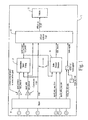
- Fig. 1 is a schematic system level view of a work machine configured for carrying out an embodiment of the method of the present invention for sensing wheel slippage and automatically engaging a differential lock;
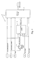
- Fig. 2 is a schematic illustration of various inputs used in the method of the present invention.
- Fig. 3 is a schematic illustration of a portion of the logic of the method of the present invention.
- Fig. 4 is a schematic illustration of another portion of the logic of the method of the present invention.
- Fig. 1 there is shown a schematic system level view of a work vehicle 10 which is configured for carrying out an embodiment of the method of the present invention for sensing wheel slippage and automatically engaging a differential lock (also referred to as "difflock" herein).
- Work vehicle 10 could be a construction vehicle, agricultural vehicle or other type of work vehicle.
- Fig. 1 generally corresponds to the inputs, control logic and outputs for an electronic control unit (ECU) 12 onboard work vehicle 10.
- ECU 12 generally includes control logic for carrying out transmission speed scaling (box 14), radar dropout detection (box 16), and difflock on/off logic (box 18).
- Inputs to ECU 12 are shown in box 20, and outputs are shown in box 22.
- the various inputs shown in box 20 and the radar dropout detection shown in box 16 will be described in more detail below with regard to Fig. 2 .
- the transmission speed scaling shown in block 14 will be described in more detail below with regard to Fig. 3 .
- the difflock on/off logic shown in box 18 will be described in more detail below with regard to Fig. 4 .
- a drive train component 24 provides an output signal "speed_trans_out" which is used to calculate a ground speed of work vehicle 10 by ECU 12.
- drive train component 24 is preferably in the form of a transmission output shaft and corresponding sensor providing the transmission speed output signal.
- the box labeled gear position 26 is a sensor providing a sensor output signal with an indication of whether a gear shift lever in an operators cab is in a forward, neutral or reverse position.
- the differential lock may only be automatically engaged when the gear shift lever is in the forward or reverse positions, and thus this signal provides an input to the boolean logic in determining whether the difflock may be engaged.
- the box labeled brake pedal position 28 provides an output signal indicating whether the service brakes of work vehicle 10 have been engaged. The difflock is not automatically engaged if the brake pedal has been depressed.
- the box labeled radar 30 corresponds to a radar which is used to sense an absolute ground speed of work vehicle 10.
- the radar includes a front horn 32 and a rear horn 34 positioned at an angle ⁇ therebetween (e.g., 90°), which are positioned to reflect radar signals at an angle off of the ground surface.
- Front horn 32 is positioned at a forward angle relative to the direction of travel of work vehicle 10, and provides an output signal "radar_machine_speed_front_horn" corresponding to the absolute ground speed sensed by front horn 32.
- rear horn 34 is positioned at a rearward angle relative to the direction of travel of work vehicle 10, and provides an output signal "radar_machine_speed_rear_horn” corresponding to the absolute ground speed of work vehicle 10 sensed by rear horn 34.
- the radar unit also provides a composite output signal labeled "radar_machine_speed”.
- Input signal 36 is the unscaled absolute ground speed of work vehicle 10 which is sensed using the radar (composite radar signal), converted to appropriate units as shown in Fig. 1 .
- Input 36 is transmitted via line 42 to box 44 for speed error correction, and is also transmitted via line 46 to boolean operators making sure that certain operating conditions exist.
- Boolean operators at boxes 48, 50 and 52 ensure that scaling of the radar signal only occurs if the ground speed of work vehicle 10 is greater than 20 kilometers per hour and less than 30 kilometers per hour.
- the output from box 52 is a yes (1) or no (0) which is transmitted as an input to boolean operator 54.
- Input 38 is a signal value indicating whether the gear shift is in the forward, neutral or reverse position, and is received from gear position 26 in Fig. 2 .
- input 38 has a value of 0, 1 or 2 with the value 2 indicating that the gear shift is in the forward position.
- the value of the input signal is compared at boolean operator 56 with a constant value from box 58 (i.e., in this case, the value 2) and an output signal is provided to boolean operator 54.
- the output signal from boolean operator 56 is true (1) if the gear shift lever is determined to be in a forward position, and false (0) if not.
- Boolean operator 54 is basically a switch which passes the value of the top line or the bottom line, depending upon the value of the signal from boolean operator 56. If the gear shift lever is not in a forward position, then a false (0) value is passed through boolean operator 54. On the other hand, if the gear shift lever is determined to be in a forward position, then the value of the top line is passed through boolean operator 54, in this instance a true (1) or false (0) representing whether scaling is to take place dependent upon the operating speed of work vehicle 10. It will thus be apparent that an output signal of one from boolean operator 54 only occurs if the gear shift lever is in the forward position and the sensed operating speed is within a particular range.
- Boolean operator 60 receives the output signal from boolean operator 54. If the signal value is high (i.e., a value of 1) then boolean operator 60 basically acts as a switch to pass through the value of the top line corresponding to a corrected speed error signal. Otherwise, boolean operator 60 passes through a false (0) value from the bottom line. In the event the top line is passed through, the value is a difference between a sensed absolute ground speed of work vehicle 10 and a scaled, calculated ground speed of work vehicle 10, as will be described in more detail hereinafter.
- the output signal from boolean operator 60 is passed to an integrator 62, and desirably is a small number indicating a small difference between the sensed and calculated ground speeds. Such errors between the sensed and calculated ground speeds can result, e.g., because of differing tire diameters caused by inflation pressures within tires, tread wear on tires, loading on work vehicle 10, etc.
- integrator 62 integrates the speed error signal over a specified time period (e.g., approximately 10 minutes) and can be used to detect an abrupt change in the error signal over time.
- Integrator 62 provides an output signal in the form of a scaling factor which is transmitted to box 64.
- the scaling factor is used as an adjustment to the calculated ground speed represented by input signal 40, converted to appropriate units as shown in Fig. 1 .
- the adjusted, calculated ground speed is fed back via line 66 in a closed loop fashion to an input of box 44.
- This continual closed loop correction between the sensed and calculated ground speeds using the scaling factor from integrator 62 should result in the scaled, calculated ground speed being closer over time to the sensed ground speed at the input to box 44, thus resulting in a smaller speed error correction output from box 44 over time.
- the output signal over time at output 68 thus should be close to the sensed ground speed of work vehicle 10.
- the scaling factor from integrator 62 is stored to a flash memory as indicated by box 70, and is restored as indicated by box 71 as in input to integrator 62 at machine startup.
- the scaled, calculated ground speed is transmitted to difflock on/off logic 18, and also is transmitted as an input to radar dropout detection logic 16.
- Input signals to radar dropout detection 16 are also received from front horn 32 and rear horn 34 of the radar unit ( Fig. 2 ).
- radar dropout detection 16 is used to detect a signal dropout resulting from radar transmission onto a highly reflective ground surface such as water. For example, as the work vehicle 10 moves across an area of standing water, the front horn 32 would first experience a signal dropout while the rear horn 34 would continue to provide a signal while moving into the water and then also lose signal when transmitting onto the water. If the scaled, calculated ground speed input signal to radar dropout detection 16 indicates that the wheels are still turning, while one or both of the radar horns have experienced signal dropout, then an output signal is provided from radar dropout detection 16 indicating such to difflock on/off logic 18.
- the unscaled, composite radar signal indicating the absolute ground speed of work machine 10 is transmitted as an input for difflock latch conditions 72 and radar speed scaling 74.
- Radar speed scaling 74 generally is in the form of a memory with a lookup table correlating the unscaled radar ground speed of work vehicle 10 with a corresponding threshold value at which the differential lock is to be automatically engaged. In other words, for a given sensed absolute ground speed using a radar, a corresponding threshold value is compared against a scaled, calculated ground speed. If the scaled, calculated ground speed is higher than the threshold value, then the difflock is automatically engaged.
- the scaling of the speed radar signal to the corresponding threshold value is shown as an approximate linear relationship in Fig. 4 . However, it is to be understood that the scaling of the speed radar signal to a corresponding threshold value need not necessarily be a linear relationship across the range of input speed radar signals.
- the output from speed radar scaling 74 thus corresponds to a threshold value at which the differential lock is automatically engaged.
- a block 76 labeled difflock engagement conditions is used to determine whether to automatically engage the difflock. If the scaled, calculated ground speed is less than a maximum value (i.e., 12kph) and higher than the scaled radar signal (i.e., threshold value), and the brake is not applied, and radar dropout has not been detected, then the difflock engagement conditions are true (1) and a corresponding signal is output to difflock latch conditions 72.
- the various latch conditions for automatically engaging the difflock are shown in difflock latch conditions block 72.
Landscapes
- Engineering & Computer Science (AREA)
- Chemical & Material Sciences (AREA)
- Combustion & Propulsion (AREA)
- Transportation (AREA)
- Mechanical Engineering (AREA)
- Control Of Transmission Device (AREA)
- Arrangement And Mounting Of Devices That Control Transmission Of Motive Force (AREA)
- Retarders (AREA)
- Regulating Braking Force (AREA)
- Operation Control Of Excavators (AREA)
Abstract
Description
- The present invention relates to work vehicles, and, more particularly, to methods of determining wheel slippage and engaging a differential lock in a work vehicle.
- Work vehicles, such as agricultural, construction or forestry work vehicles, typically include an internal combustion engine which drives a transmission, which in turn drives at least one axle through a differential lock. In the event that traction is lost and a wheel begins to slip, all power is applied to the slipping wheel through the differential and the opposite wheel receives little or no torque. In the case of a rear wheel drive work vehicle, an operator can typically lock the rear wheels together by operating a foot or hand lever to engage the differential lock. By engaging the differential lock, the wheels spin at the same speed and the wheel that is not spinning can be used to regain traction.
- The assignee of the present invention, John Deere, also manufactures and sells a front wheel assist work vehicle used primarily in the construction and agricultural markets (also known as a mechanical front wheel drive, or MFWD). With an MFWD, the front wheels are typically locked together through a differential using an electric switch on the floor.
- Certain types of work vehicles, such as front end loaders, may be used to push earth or the like, resulting in a load which could cause wheel slippage. Another example is an agricultural tractor pulling a pull-type implement through wet soil, in which event the drive wheels could also slip. Under such conditions, it may be desirable to automatically engage the differential lock of the rear and/or front differentials without operator intervention, thereby allowing the operator to focus on the work operation at hand.
- What is needed in the art is a method of automatically engaging a differential lock in a work vehicle upon accurate detection of wheel slippage of one or more axles.
- The invention in one form is directed to a method of determining wheel slippage in a work vehicle, including the steps of: sensing an absolute ground speed of the work vehicle; calculating a ground speed of the work vehicle using at least one drive train component; comparing the absolute ground speed with the calculated ground speed; generating a scaling factor based upon the comparison; and adjusting the calculated ground speed using the scaling factor.
- The invention in another form is directed to a method of determining wheel slippage in a work vehicle, including the steps of: sensing an absolute ground speed of the work vehicle; calculating a ground speed of the work vehicle using at least one drive train component; scaling the absolute ground speed to a threshold value; comparing the calculated ground speed with the threshold value; and engaging a differential lock if the calculated ground speed is greater than the threshold value.
-
Fig. 1 is a schematic system level view of a work machine configured for carrying out an embodiment of the method of the present invention for sensing wheel slippage and automatically engaging a differential lock; -
Fig. 2 is a schematic illustration of various inputs used in the method of the present invention; -
Fig. 3 is a schematic illustration of a portion of the logic of the method of the present invention; and -
Fig. 4 is a schematic illustration of another portion of the logic of the method of the present invention. - Referring now to the drawings, and more particularly to
Fig. 1 , there is shown a schematic system level view of awork vehicle 10 which is configured for carrying out an embodiment of the method of the present invention for sensing wheel slippage and automatically engaging a differential lock (also referred to as "difflock" herein).Work vehicle 10 could be a construction vehicle, agricultural vehicle or other type of work vehicle. -
Fig. 1 generally corresponds to the inputs, control logic and outputs for an electronic control unit (ECU) 12onboard work vehicle 10. As shown,ECU 12 generally includes control logic for carrying out transmission speed scaling (box 14), radar dropout detection (box 16), and difflock on/off logic (box 18). Inputs toECU 12 are shown inbox 20, and outputs are shown in box 22. The various inputs shown inbox 20 and the radar dropout detection shown inbox 16 will be described in more detail below with regard toFig. 2 . The transmission speed scaling shown inblock 14 will be described in more detail below with regard toFig. 3 . The difflock on/off logic shown inbox 18 will be described in more detail below with regard toFig. 4 . - Referring now to
Fig. 2 , there is shown a schematic illustration of the various inputs used in the method of the present invention illustrated inFig. 1 . Adrive train component 24 provides an output signal "speed_trans_out" which is used to calculate a ground speed ofwork vehicle 10 by ECU 12. In the embodiment shown,drive train component 24 is preferably in the form of a transmission output shaft and corresponding sensor providing the transmission speed output signal. - The box labeled gear position 26 is a sensor providing a sensor output signal with an indication of whether a gear shift lever in an operators cab is in a forward, neutral or reverse position. The differential lock may only be automatically engaged when the gear shift lever is in the forward or reverse positions, and thus this signal provides an input to the boolean logic in determining whether the difflock may be engaged.
- The box labeled
brake pedal position 28 provides an output signal indicating whether the service brakes ofwork vehicle 10 have been engaged. The difflock is not automatically engaged if the brake pedal has been depressed. - The box labeled
radar 30 corresponds to a radar which is used to sense an absolute ground speed ofwork vehicle 10. As shown withinbox 30, the radar includes afront horn 32 and arear horn 34 positioned at an angle α therebetween (e.g., 90°), which are positioned to reflect radar signals at an angle off of the ground surface.Front horn 32 is positioned at a forward angle relative to the direction of travel ofwork vehicle 10, and provides an output signal "radar_machine_speed_front_horn" corresponding to the absolute ground speed sensed byfront horn 32. Similarly,rear horn 34 is positioned at a rearward angle relative to the direction of travel ofwork vehicle 10, and provides an output signal "radar_machine_speed_rear_horn" corresponding to the absolute ground speed ofwork vehicle 10 sensed byrear horn 34. The radar unit also provides a composite output signal labeled "radar_machine_speed". - Referring now to
Fig. 3 , the transmission speed scaling shown atbox 14 inFig. 1 will be described in greater detail. There are three primary inputs to this control logic, indicated atinputs Input signal 36 is the unscaled absolute ground speed ofwork vehicle 10 which is sensed using the radar (composite radar signal), converted to appropriate units as shown inFig. 1 .Input 36 is transmitted vialine 42 tobox 44 for speed error correction, and is also transmitted vialine 46 to boolean operators making sure that certain operating conditions exist. Boolean operators atboxes work vehicle 10 is greater than 20 kilometers per hour and less than 30 kilometers per hour. The output frombox 52 is a yes (1) or no (0) which is transmitted as an input toboolean operator 54. -
Input 38 is a signal value indicating whether the gear shift is in the forward, neutral or reverse position, and is received from gear position 26 inFig. 2 . In the example shown,input 38 has a value of 0, 1 or 2 with thevalue 2 indicating that the gear shift is in the forward position. The value of the input signal is compared atboolean operator 56 with a constant value from box 58 (i.e., in this case, the value 2) and an output signal is provided toboolean operator 54. In the example shown, the output signal fromboolean operator 56 is true (1) if the gear shift lever is determined to be in a forward position, and false (0) if not. -
Boolean operator 54 is basically a switch which passes the value of the top line or the bottom line, depending upon the value of the signal fromboolean operator 56. If the gear shift lever is not in a forward position, then a false (0) value is passed throughboolean operator 54. On the other hand, if the gear shift lever is determined to be in a forward position, then the value of the top line is passed throughboolean operator 54, in this instance a true (1) or false (0) representing whether scaling is to take place dependent upon the operating speed ofwork vehicle 10. It will thus be apparent that an output signal of one fromboolean operator 54 only occurs if the gear shift lever is in the forward position and the sensed operating speed is within a particular range. -
Boolean operator 60 receives the output signal fromboolean operator 54. If the signal value is high (i.e., a value of 1) thenboolean operator 60 basically acts as a switch to pass through the value of the top line corresponding to a corrected speed error signal. Otherwise,boolean operator 60 passes through a false (0) value from the bottom line. In the event the top line is passed through, the value is a difference between a sensed absolute ground speed ofwork vehicle 10 and a scaled, calculated ground speed ofwork vehicle 10, as will be described in more detail hereinafter. - The output signal from
boolean operator 60 is passed to anintegrator 62, and desirably is a small number indicating a small difference between the sensed and calculated ground speeds. Such errors between the sensed and calculated ground speeds can result, e.g., because of differing tire diameters caused by inflation pressures within tires, tread wear on tires, loading onwork vehicle 10, etc. In the embodiment shown,integrator 62 integrates the speed error signal over a specified time period (e.g., approximately 10 minutes) and can be used to detect an abrupt change in the error signal over time. -
Integrator 62 provides an output signal in the form of a scaling factor which is transmitted tobox 64. The scaling factor is used as an adjustment to the calculated ground speed represented byinput signal 40, converted to appropriate units as shown inFig. 1 . The adjusted, calculated ground speed is fed back vialine 66 in a closed loop fashion to an input ofbox 44. This continual closed loop correction between the sensed and calculated ground speeds using the scaling factor fromintegrator 62 should result in the scaled, calculated ground speed being closer over time to the sensed ground speed at the input tobox 44, thus resulting in a smaller speed error correction output frombox 44 over time. The output signal over time atoutput 68 thus should be close to the sensed ground speed ofwork vehicle 10. - At shutdown of
work vehicle 10, the scaling factor fromintegrator 62 is stored to a flash memory as indicated bybox 70, and is restored as indicated bybox 71 as in input tointegrator 62 at machine startup. - As shown in
Fig. 1 , the scaled, calculated ground speed is transmitted to difflock on/offlogic 18, and also is transmitted as an input to radardropout detection logic 16. Input signals toradar dropout detection 16 are also received fromfront horn 32 andrear horn 34 of the radar unit (Fig. 2 ). Generally,radar dropout detection 16 is used to detect a signal dropout resulting from radar transmission onto a highly reflective ground surface such as water. For example, as thework vehicle 10 moves across an area of standing water, thefront horn 32 would first experience a signal dropout while therear horn 34 would continue to provide a signal while moving into the water and then also lose signal when transmitting onto the water. If the scaled, calculated ground speed input signal toradar dropout detection 16 indicates that the wheels are still turning, while one or both of the radar horns have experienced signal dropout, then an output signal is provided fromradar dropout detection 16 indicating such to difflock on/offlogic 18. - Referring now to
Fig. 4 , the difflock on/offlogic 18 will be described in greater detail. The unscaled, composite radar signal indicating the absolute ground speed ofwork machine 10 is transmitted as an input fordifflock latch conditions 72 and radar speed scaling 74. Radar speed scaling 74 generally is in the form of a memory with a lookup table correlating the unscaled radar ground speed ofwork vehicle 10 with a corresponding threshold value at which the differential lock is to be automatically engaged. In other words, for a given sensed absolute ground speed using a radar, a corresponding threshold value is compared against a scaled, calculated ground speed. If the scaled, calculated ground speed is higher than the threshold value, then the difflock is automatically engaged. The scaling of the speed radar signal to the corresponding threshold value is shown as an approximate linear relationship inFig. 4 . However, it is to be understood that the scaling of the speed radar signal to a corresponding threshold value need not necessarily be a linear relationship across the range of input speed radar signals. The output from speed radar scaling 74 thus corresponds to a threshold value at which the differential lock is automatically engaged. - A
block 76 labeled difflock engagement conditions is used to determine whether to automatically engage the difflock. If the scaled, calculated ground speed is less than a maximum value (i.e., 12kph) and higher than the scaled radar signal (i.e., threshold value), and the brake is not applied, and radar dropout has not been detected, then the difflock engagement conditions are true (1) and a corresponding signal is output to difflock latch conditions 72. The various latch conditions for automatically engaging the difflock are shown in difflock latch conditions block 72. - Having described the preferred embodiment, it will become apparent that various modifications can be made without departing from the scope of the invention as defined in the accompanying claims.
Claims (19)
- A method of determining wheel slippage in a work vehicle, comprising the steps of:sensing an absolute ground speed of the work vehicle;calculating a ground speed of the work vehicle using at least one drive train component;comparing said absolute ground speed with said calculated ground speed;generating a scaling factor based upon said comparison; andadjusting said calculated ground speed using said scaling factor.
- The method of determining wheel slippage in a work vehicle of claim 1, including the step of feeding back said adjusted calculated ground speed to said comparing step in a closed loop fashion.
- The method of determining wheel slippage in a work vehicle of claim 1, wherein said comparing step results in a speed error signal, and said generating step is carried out by integrating said speed error signal over time to generate said scaling factor.
- The method of determining wheel slippage in a work vehicle of claim 3, wherein said integration can be used to detect an abrupt change in said error signal over time.
- The method of determining wheel slippage in a work vehicle of claim 1, including the step of outputting a scaled calculated ground speed based upon said adjusted calculated ground speed.
- The method of determining wheel slippage in a work vehicle of claim 1, wherein said calculating step comprises calculating a ground speed of the work vehicle using a transmission output speed.
- The method of determining wheel slippage in a work vehicle of claim 1, wherein said absolute ground speed is sensed using a radar.
- The method of determining wheel slippage in a work vehicle of claim 1, including the step of scaling said absolute ground speed to a threshold value at which a differential lock is engaged.
- The method of determining wheel slippage in a work vehicle of claim 8, including the step of comparing said scaled absolute ground speed with said scaled calculated ground speed.
- The method of determining wheel slippage in a work vehicle of claim 9, including the step of engaging a differential lock if said scaled calculated ground speed is greater than said scaled absolute ground speed.
- The method of determining wheel slippage in a work vehicle of claim 10, wherein said absolute ground speed is sensed using a radar, and including the step of not engaging said differential lock if said radar has a signal fallout from a reflective ground surface.
- The method of determining wheel slippage in a work vehicle of claim 11, wherein said radar has two sensing horns, and said signal fallout is determined when one said sensing horn ceases providing an output while an other said sensing horn continues providing an output.
- A method of determining wheel slippage in a work vehicle, comprising the steps of:sensing an absolute ground speed of the work vehicle;calculating a ground speed of the work vehicle using at least one drive train component;seating said absolute ground speed to a threshold value;comparing said said calculated ground speed with said threshold value; andengaging a differential lock if said calculated ground speed is greater than said threshold value.
- The method of determining wheel slippage in a work vehicle of claim 13, wherein said absolute ground speed is sensed using a radar.
- The method of determining wheel slippage in a work vehicle of claim 13, wherein said threshold value comprises one of a plurality of threshold values stored in a memory, each said threshold value corresponding to a different said sensed absolute ground speed of the work vehicle.
- The method of determining wheel slippage in a work vehicle of claim 15, wherein said memory includes a lookup table with said plurality of threshold values.
- The method of determining wheel slippage in a work vehicle of claim 13, wherein said absolute ground speed is sensed using a radar, and including the step of not engaging said differential lock if said radar has a signal fallout from a reflective ground surface.
- The method of determining wheel slippage in a work vehicle of claim 17, wherein said radar has two sensing horns, and said signal fallout is determined when one said sensing horn ceases providing an output while an other said sensing horn continues providing an output.
- The method of determining wheel slippage in a work vehicle of claim 13, wherein said calculating step comprises calculating a ground speed of the work vehicle using a transmission output speed.
Applications Claiming Priority (1)
| Application Number | Priority Date | Filing Date | Title |
|---|---|---|---|
| US11/678,118 US7856303B2 (en) | 2007-02-23 | 2007-02-23 | Method of determining wheel slippage and engaging a differential lock in a work vehicle |
Publications (2)
| Publication Number | Publication Date |
|---|---|
| EP1961603A1 true EP1961603A1 (en) | 2008-08-27 |
| EP1961603B1 EP1961603B1 (en) | 2009-12-23 |
Family
ID=39370911
Family Applications (1)
| Application Number | Title | Priority Date | Filing Date |
|---|---|---|---|
| EP07012245A Not-in-force EP1961603B1 (en) | 2007-02-23 | 2007-06-22 | Method of determining wheel slippage and engaging a differential lock in a work vehicle |
Country Status (6)
| Country | Link |
|---|---|
| US (1) | US7856303B2 (en) |
| EP (1) | EP1961603B1 (en) |
| JP (1) | JP4799508B2 (en) |
| CN (1) | CN101251185B (en) |
| CA (1) | CA2592647C (en) |
| DE (1) | DE602007003947D1 (en) |
Families Citing this family (11)
| Publication number | Priority date | Publication date | Assignee | Title |
|---|---|---|---|---|
| US9539097B2 (en) * | 2007-11-08 | 2017-01-10 | Linares Medical Devices, Llc | Hip and knee joint assemblies incorporating debris collection architecture between the ball and seat interface |
| US8626404B2 (en) * | 2010-11-19 | 2014-01-07 | Caterpillar Inc. | Motor grader wheel slip control for cut to grade |
| US20120221222A1 (en) * | 2011-02-28 | 2012-08-30 | Eric Anderson | Method of compensating for vehicle kinematics in controlling independent wheel motors |
| US9709969B2 (en) | 2013-03-15 | 2017-07-18 | Deere & Company | Methods and apparatus to control machine configurations |
| DE102014207088B4 (en) * | 2014-04-14 | 2020-07-23 | Zf Friedrichshafen Ag | Procedure for releasing a stuck vehicle |
| SE539607C2 (en) * | 2014-06-24 | 2017-10-17 | Dsensed Tech Ab | A method and system for controlling the stability and response of a vehicle |
| US10053100B2 (en) * | 2015-10-09 | 2018-08-21 | Cnh Industrial America Llc | Slip control system for an off-road vehicle |
| EP3208380B1 (en) * | 2016-02-17 | 2021-08-11 | Joseph Vögele AG | Method of controlling a road paver with wheel running gear and road paver with wheel running gear |
| US11136040B2 (en) * | 2018-05-21 | 2021-10-05 | Deere & Company | IMU based traction control for wheeled or tracked machine |
| DE102019204129A1 (en) * | 2019-03-26 | 2020-10-01 | Zf Friedrichshafen Ag | Method for controlling a driving dynamics function of a work machine |
| CN114932810B (en) * | 2021-07-12 | 2025-03-04 | 长城汽车股份有限公司 | Control method, device, medium and equipment of electronic differential lock |
Citations (4)
| Publication number | Priority date | Publication date | Assignee | Title |
|---|---|---|---|---|
| EP0457743A1 (en) * | 1990-05-14 | 1991-11-21 | Valmet Oy | Method and control system for switching on/off of the differential lock of a tractor or of a corresponding working machine |
| EP0500403A1 (en) * | 1991-02-18 | 1992-08-26 | Automobiles Peugeot | Method and device for regulating traction slip of driven wheels of a vehicle |
| EP1090799A2 (en) * | 1999-10-05 | 2001-04-11 | Deere & Company | Work vehicle with automatic differential lock |
| US20040176898A1 (en) * | 2003-03-06 | 2004-09-09 | Delphi Technologies Inc. | Tcs stability utilizing a controlled center coupling and controlled brake system |
Family Cites Families (14)
| Publication number | Priority date | Publication date | Assignee | Title |
|---|---|---|---|---|
| JPS5219297Y2 (en) * | 1972-11-02 | 1977-05-02 | ||
| JPS5630662A (en) * | 1979-08-22 | 1981-03-27 | Komatsu Ltd | Slip ratio detector |
| JPS6147577A (en) * | 1984-08-11 | 1986-03-08 | Iseki & Co Ltd | Ground speed detector |
| JPH0735133B2 (en) * | 1988-07-01 | 1995-04-19 | 日産自動車株式会社 | Vehicular differential limiting controller |
| US5574643A (en) * | 1994-07-15 | 1996-11-12 | Caterpillar Inc. | Traction control for a machine with electronic engine and transmission controls |
| DE4427040C2 (en) * | 1994-07-29 | 1998-05-20 | Steyr Daimler Puch Ag | Method for controlling a locking clutch acting as a differential lock |
| JPH0858410A (en) * | 1994-08-23 | 1996-03-05 | Iseki & Co Ltd | Travel drive controller for tractor |
| JPH10119743A (en) * | 1996-10-23 | 1998-05-12 | Aisin Seiki Co Ltd | Vehicle motion control device |
| US5944769A (en) * | 1996-11-08 | 1999-08-31 | Zip2 Corporation | Interactive network directory service with integrated maps and directions |
| AT405158B (en) * | 1996-12-04 | 1999-06-25 | Steyr Daimler Puch Ag | METHOD FOR AUTOMATICALLY CONTROLLING THE LOCKING CLUTCHES OF AN ALL-WHEEL DRIVE VEHICLE AND VEHICLE WITH ARTICULATED STEERING AND LOCKABLE DIFFERENTIALS |
| US6583754B2 (en) * | 2001-10-31 | 2003-06-24 | Deere & Company | Fast fourier transform signal processing method for doppler radar speed sensor |
| US6600979B1 (en) * | 2002-02-26 | 2003-07-29 | General Electric Company | Method and system for determining an inertially-adjusted vehicle reference speed |
| US6885930B2 (en) * | 2003-07-31 | 2005-04-26 | Siemens Energy & Automation, Inc. | System and method for slip slide control |
| JP4779452B2 (en) * | 2005-06-01 | 2011-09-28 | トヨタ自動車株式会社 | Vehicle control device |
-
2007
- 2007-02-23 US US11/678,118 patent/US7856303B2/en not_active Expired - Fee Related
- 2007-06-22 DE DE602007003947T patent/DE602007003947D1/en active Active
- 2007-06-22 EP EP07012245A patent/EP1961603B1/en not_active Not-in-force
- 2007-06-26 CA CA002592647A patent/CA2592647C/en not_active Expired - Fee Related
- 2007-07-27 CN CN2007101367639A patent/CN101251185B/en not_active Expired - Fee Related
- 2007-08-14 JP JP2007211188A patent/JP4799508B2/en not_active Expired - Fee Related
Patent Citations (4)
| Publication number | Priority date | Publication date | Assignee | Title |
|---|---|---|---|---|
| EP0457743A1 (en) * | 1990-05-14 | 1991-11-21 | Valmet Oy | Method and control system for switching on/off of the differential lock of a tractor or of a corresponding working machine |
| EP0500403A1 (en) * | 1991-02-18 | 1992-08-26 | Automobiles Peugeot | Method and device for regulating traction slip of driven wheels of a vehicle |
| EP1090799A2 (en) * | 1999-10-05 | 2001-04-11 | Deere & Company | Work vehicle with automatic differential lock |
| US20040176898A1 (en) * | 2003-03-06 | 2004-09-09 | Delphi Technologies Inc. | Tcs stability utilizing a controlled center coupling and controlled brake system |
Also Published As
| Publication number | Publication date |
|---|---|
| US20080208428A1 (en) | 2008-08-28 |
| CN101251185A (en) | 2008-08-27 |
| JP4799508B2 (en) | 2011-10-26 |
| US7856303B2 (en) | 2010-12-21 |
| JP2008208986A (en) | 2008-09-11 |
| CN101251185B (en) | 2013-04-17 |
| CA2592647C (en) | 2010-01-19 |
| EP1961603B1 (en) | 2009-12-23 |
| DE602007003947D1 (en) | 2010-02-04 |
| CA2592647A1 (en) | 2008-08-23 |
Similar Documents
| Publication | Publication Date | Title |
|---|---|---|
| EP1961603B1 (en) | Method of determining wheel slippage and engaging a differential lock in a work vehicle | |
| US8364369B2 (en) | Low range drive ratio transfer changeover anti-rollback system and method | |
| US20160251005A1 (en) | Vehicle Braking Methods and Related Apparatuses | |
| US20150321671A1 (en) | Vehicle Speed Control System | |
| US10286893B2 (en) | Device for operating an all-wheel-drive agricultural commercial vehicle | |
| CN107975593B (en) | Work vehicle drive assembly with electric motor overspeed protection | |
| US8676459B2 (en) | Powertrain for a vehcile and system and method for controlling the powertrain | |
| US20100318308A1 (en) | Calibration in indirect tire pressure monitoring | |
| US20100076645A1 (en) | Method for operating a motor vehicle | |
| US20150224978A1 (en) | Braking/driving force control device | |
| US8000877B2 (en) | Fuel economy system and method for a vehicle | |
| US20080204214A1 (en) | Method for Controlling the Driving Operating of Motor Vehicles or Other Vehicles | |
| US11084529B2 (en) | Utility vehicle braking | |
| JP5633026B2 (en) | Braking system integrated with continuous service brake | |
| US11834095B2 (en) | Utility vehicle braking | |
| CN104228941A (en) | Caculation device for vehicle steering angle | |
| EP2137008B1 (en) | Indirect tire pressure monitoring | |
| CA2610548C (en) | Fuel economy system and method for a vehicle | |
| EP2558320A1 (en) | System for controlling a torque transfer actuator with multiple modes of operation | |
| US7979188B2 (en) | Method for activating and deactivating the four-wheel drive of service and working vehicles without interactive differential locks | |
| US6554376B2 (en) | Method and device for adjusting the braking and/or driving effect on the wheels of a motor vehicle | |
| US20060207810A1 (en) | Hybrid drive | |
| EP2177414B1 (en) | Method for determining the tyre radius variation between the front and rear wheels of a motor vehicle | |
| US20150081190A1 (en) | Traction system and a method for controlling said traction system | |
| US20050102087A1 (en) | Vehicle behavior estimating device and vehicle behavior controlling device |
Legal Events
| Date | Code | Title | Description |
|---|---|---|---|
| PUAI | Public reference made under article 153(3) epc to a published international application that has entered the european phase |
Free format text: ORIGINAL CODE: 0009012 |
|
| AK | Designated contracting states |
Kind code of ref document: A1 Designated state(s): AT BE BG CH CY CZ DE DK EE ES FI FR GB GR HU IE IS IT LI LT LU LV MC MT NL PL PT RO SE SI SK TR |
|
| AX | Request for extension of the european patent |
Extension state: AL BA HR MK RS |
|
| 17P | Request for examination filed |
Effective date: 20081209 |
|
| AKX | Designation fees paid |
Designated state(s): DE GB SE |
|
| GRAP | Despatch of communication of intention to grant a patent |
Free format text: ORIGINAL CODE: EPIDOSNIGR1 |
|
| GRAS | Grant fee paid |
Free format text: ORIGINAL CODE: EPIDOSNIGR3 |
|
| GRAA | (expected) grant |
Free format text: ORIGINAL CODE: 0009210 |
|
| AK | Designated contracting states |
Kind code of ref document: B1 Designated state(s): DE GB SE |
|
| REG | Reference to a national code |
Ref country code: GB Ref legal event code: FG4D |
|
| REF | Corresponds to: |
Ref document number: 602007003947 Country of ref document: DE Date of ref document: 20100204 Kind code of ref document: P |
|
| REG | Reference to a national code |
Ref country code: SE Ref legal event code: TRGR |
|
| PLBE | No opposition filed within time limit |
Free format text: ORIGINAL CODE: 0009261 |
|
| STAA | Information on the status of an ep patent application or granted ep patent |
Free format text: STATUS: NO OPPOSITION FILED WITHIN TIME LIMIT |
|
| 26N | No opposition filed |
Effective date: 20100924 |
|
| REG | Reference to a national code |
Ref country code: DE Ref legal event code: R082 Ref document number: 602007003947 Country of ref document: DE |
|
| PGFP | Annual fee paid to national office [announced via postgrant information from national office to epo] |
Ref country code: DE Payment date: 20160519 Year of fee payment: 10 |
|
| PGFP | Annual fee paid to national office [announced via postgrant information from national office to epo] |
Ref country code: SE Payment date: 20160629 Year of fee payment: 10 |
|
| PGFP | Annual fee paid to national office [announced via postgrant information from national office to epo] |
Ref country code: GB Payment date: 20170627 Year of fee payment: 11 |
|
| REG | Reference to a national code |
Ref country code: DE Ref legal event code: R119 Ref document number: 602007003947 Country of ref document: DE |
|
| REG | Reference to a national code |
Ref country code: SE Ref legal event code: EUG |
|
| PG25 | Lapsed in a contracting state [announced via postgrant information from national office to epo] |
Ref country code: SE Free format text: LAPSE BECAUSE OF NON-PAYMENT OF DUE FEES Effective date: 20170623 |
|
| PG25 | Lapsed in a contracting state [announced via postgrant information from national office to epo] |
Ref country code: DE Free format text: LAPSE BECAUSE OF NON-PAYMENT OF DUE FEES Effective date: 20180103 |
|
| GBPC | Gb: european patent ceased through non-payment of renewal fee |
Effective date: 20180622 |
|
| PG25 | Lapsed in a contracting state [announced via postgrant information from national office to epo] |
Ref country code: GB Free format text: LAPSE BECAUSE OF NON-PAYMENT OF DUE FEES Effective date: 20180622 |