EP1960932B1 - Apparatus and methods for multi-channel metering - Google Patents
Apparatus and methods for multi-channel metering Download PDFInfo
- Publication number
- EP1960932B1 EP1960932B1 EP06849894.8A EP06849894A EP1960932B1 EP 1960932 B1 EP1960932 B1 EP 1960932B1 EP 06849894 A EP06849894 A EP 06849894A EP 1960932 B1 EP1960932 B1 EP 1960932B1
- Authority
- EP
- European Patent Office
- Prior art keywords
- operable
- meter head
- customer
- meter
- communication
- Prior art date
- Legal status (The legal status is an assumption and is not a legal conclusion. Google has not performed a legal analysis and makes no representation as to the accuracy of the status listed.)
- Not-in-force
Links
Images


Classifications
-
- G—PHYSICS
- G01—MEASURING; TESTING
- G01R—MEASURING ELECTRIC VARIABLES; MEASURING MAGNETIC VARIABLES
- G01R22/00—Arrangements for measuring time integral of electric power or current, e.g. electricity meters
- G01R22/06—Arrangements for measuring time integral of electric power or current, e.g. electricity meters by electronic methods
- G01R22/061—Details of electronic electricity meters
- G01R22/066—Arrangements for avoiding or indicating fraudulent use
-
- H—ELECTRICITY
- H04—ELECTRIC COMMUNICATION TECHNIQUE
- H04Q—SELECTING
- H04Q9/00—Arrangements in telecontrol or telemetry systems for selectively calling a substation from a main station, in which substation desired apparatus is selected for applying a control signal thereto or for obtaining measured values therefrom
-
- G—PHYSICS
- G01—MEASURING; TESTING
- G01R—MEASURING ELECTRIC VARIABLES; MEASURING MAGNETIC VARIABLES
- G01R22/00—Arrangements for measuring time integral of electric power or current, e.g. electricity meters
- G01R22/06—Arrangements for measuring time integral of electric power or current, e.g. electricity meters by electronic methods
- G01R22/061—Details of electronic electricity meters
- G01R22/063—Details of electronic electricity meters related to remote communication
-
- H—ELECTRICITY
- H02—GENERATION; CONVERSION OR DISTRIBUTION OF ELECTRIC POWER
- H02J—ELECTRIC POWER NETWORKS; CIRCUIT ARRANGEMENTS OR SYSTEMS FOR SUPPLYING OR DISTRIBUTING ELECTRIC POWER; SYSTEMS FOR STORING ELECTRIC ENERGY
- H02J13/00—Circuit arrangements for providing remote monitoring or remote control of equipment in a power distribution network
- H02J13/13—Circuit arrangements for providing remote monitoring or remote control of equipment in a power distribution network characterised by the transmission of data to equipment in the power network
- H02J13/1311—Circuit arrangements for providing remote monitoring or remote control of equipment in a power distribution network characterised by the transmission of data to equipment in the power network using the power network as support for the transmission
-
- H—ELECTRICITY
- H02—GENERATION; CONVERSION OR DISTRIBUTION OF ELECTRIC POWER
- H02J—ELECTRIC POWER NETWORKS; CIRCUIT ARRANGEMENTS OR SYSTEMS FOR SUPPLYING OR DISTRIBUTING ELECTRIC POWER; SYSTEMS FOR STORING ELECTRIC ENERGY
- H02J13/00—Circuit arrangements for providing remote monitoring or remote control of equipment in a power distribution network
- H02J13/18—Circuit arrangements for providing remote monitoring or remote control of equipment in a power distribution network characterised by the remotely-controlled equipment, e.g. converters or transformers
- H02J13/333—Circuit arrangements for providing remote monitoring or remote control of equipment in a power distribution network characterised by the remotely-controlled equipment, e.g. converters or transformers the equipment forming part of substations
-
- H—ELECTRICITY
- H04—ELECTRIC COMMUNICATION TECHNIQUE
- H04Q—SELECTING
- H04Q2209/00—Arrangements in telecontrol or telemetry systems
- H04Q2209/30—Arrangements in telecontrol or telemetry systems using a wired architecture
-
- H—ELECTRICITY
- H04—ELECTRIC COMMUNICATION TECHNIQUE
- H04Q—SELECTING
- H04Q2209/00—Arrangements in telecontrol or telemetry systems
- H04Q2209/60—Arrangements in telecontrol or telemetry systems for transmitting utility meters data, i.e. transmission of data from the reader of the utility meter
-
- Y—GENERAL TAGGING OF NEW TECHNOLOGICAL DEVELOPMENTS; GENERAL TAGGING OF CROSS-SECTIONAL TECHNOLOGIES SPANNING OVER SEVERAL SECTIONS OF THE IPC; TECHNICAL SUBJECTS COVERED BY FORMER USPC CROSS-REFERENCE ART COLLECTIONS [XRACs] AND DIGESTS
- Y02—TECHNOLOGIES OR APPLICATIONS FOR MITIGATION OR ADAPTATION AGAINST CLIMATE CHANGE
- Y02E—REDUCTION OF GREENHOUSE GAS [GHG] EMISSIONS, RELATED TO ENERGY GENERATION, TRANSMISSION OR DISTRIBUTION
- Y02E60/00—Enabling technologies; Technologies with a potential or indirect contribution to GHG emissions mitigation
-
- Y—GENERAL TAGGING OF NEW TECHNOLOGICAL DEVELOPMENTS; GENERAL TAGGING OF CROSS-SECTIONAL TECHNOLOGIES SPANNING OVER SEVERAL SECTIONS OF THE IPC; TECHNICAL SUBJECTS COVERED BY FORMER USPC CROSS-REFERENCE ART COLLECTIONS [XRACs] AND DIGESTS
- Y04—INFORMATION OR COMMUNICATION TECHNOLOGIES HAVING AN IMPACT ON OTHER TECHNOLOGY AREAS
- Y04S—SYSTEMS INTEGRATING TECHNOLOGIES RELATED TO POWER NETWORK OPERATION, COMMUNICATION OR INFORMATION TECHNOLOGIES FOR IMPROVING THE ELECTRICAL POWER GENERATION, TRANSMISSION, DISTRIBUTION, MANAGEMENT OR USAGE, i.e. SMART GRIDS
- Y04S40/00—Systems for electrical power generation, transmission, distribution or end-user application management characterised by the use of communication or information technologies, or communication or information technology specific aspects supporting them
- Y04S40/12—Systems for electrical power generation, transmission, distribution or end-user application management characterised by the use of communication or information technologies, or communication or information technology specific aspects supporting them characterised by data transport means between the monitoring, controlling or managing units and monitored, controlled or operated electrical equipment
- Y04S40/121—Systems for electrical power generation, transmission, distribution or end-user application management characterised by the use of communication or information technologies, or communication or information technology specific aspects supporting them characterised by data transport means between the monitoring, controlling or managing units and monitored, controlled or operated electrical equipment using the power network as support for the transmission
Definitions
- US 5696501 relates to an electrical metering device and a method therefor.
- the apparatus has a common node and a number of electrical metering devices connected to the node.
- the metering devices measure power consumption and transmit a signal indicative thereof to the node.
- the node calculates the power consumed and stores the results in a register.
- EP 1379012 relates to an automated and integrated meter reading procedure and transfer of obtained digital data to a remote computer system and an apparatus therefor.
- the apparatus measures power, gas, and water usage, processes the measured data, and transmits the data to a utility company substation.
- US 2005/0137813 relates to a system and method for on-line monitoring and billing of power consumption.
- the system has a metering device connected to a power line and a transponder connected to the metering device.
- the transponder receives and transmits data from and to the metering device via the power line, and receives and transmits data from and to a remotely located computer.
- One embodiment of the present invention comprises a metering device that is related to the Quadlogic ASIC-based family of meters (see U.S. Pat. No. 6,947,854 , and U.S. Pat. App. Pub. No. 20060036388 ).
- this embodiment (referred to herein for convenience as "Energy Guard") is a multi-channel meter that preferably is capable of providing much of the functionality of the above-mentioned family of meters, and further provides the improvements, features, and components listed below.
- a MiniCloset is a 24-channel metering device that can measure electric usage for up to 24 single-phase customers, 12 two-phase customer, or 8 three-phase customers.
- Preferably connected to the MiniCloset are one or more Load Control Modules (LCMs), discussed below.
- LCMs Load Control Modules
- Energy Guard preferably comprises a MiniCloset meter head module and two LCMs mounted into a steel box. Relays that allow for an electricity customer to be remotely disconnected and reconnected, along with current transformers, also are mounted into the box. See FIG. 1 .
- Energy Guard meters preferably are operable to provide:
- the invention comprises a device for measuring electricity usage, comprising: means for remote disconnection via power line communication; means for detection of electricity theft; means for tamper detection; and means for reverse voltage detection.
- the invention comprises an apparatus for multi-channel metering of electricity, comprising: (a) a meter head operable to measure electricity usage for a plurality of electricity consumer lines; (b) a transponder in communication with the meter head and operable to transmit data received from the meter head via power line communication to a remotely located computer, and to transmit data received via power line communication from the remotely located computer to the meter head; and (c) a load control module in communication with the meter head and operable to actuate connection and disconnection of each of a plurality of relays, each relay of the plurality of relays corresponding to one of the plurality of electricity consumer lines.
- the apparatus further comprises a tamper detector in communication with the meter head; (2) the tamper detector comprises a light and a reflective surface, and the meter head is operable to instruct the load control module to disconnect all of the customer lines if the tamper detector provides notification that the light is not detected reflecting from the reflective surface; (3) the apparatus further comprises a box containing the meter head, the load control module, and the relays, and wherein the tamper detector comprises a detector of ambient light entering the box; (4) the apparatus further comprises a box containing the meter head, the load control module, and the relays, and wherein the box is installed on a utility pole; (5) the apparatus further comprises means for comparing transformer energy to total energy used by the consumer lines; (6) the apparatus further comprises means for detecting reverse voltage flow through the consumer lines; (7) the apparatus further comprises a computer readable memory in communication with the meter head and a counter in communication with the meter head, the counter corresponding to a customer line and operable to count down an
- an Energy Guard metering apparatus comprises a MiniCloset (that is, a metering apparatus operable to meter a plurality of customer lines); a Scan Transponder; one or more relays operable to disconnect service to selected customers; a Load Control Module; and optical tamper detection means.
- MiniCloset and Scan Transponder referred to herein are largely the same as described in U.S. Pat. No. 6,947,854 . That is, although each has been improved over the years, the functionality and structure relevant to this description may be taken to be the same as described in that patent.
- One aspect of the invention comprises taking existing multichannel metering functionality found in the MiniCloset and adding remote connect and disconnect via PLC. Providing such additional functionality required adding new hardware and software.
- the added hardware comprises a Load Control Module (LCM) and
- connect/disconnect relays Also added was support circuitry to route signal traces to and from the main meter processor- the MiniCloset5 Meter Head.
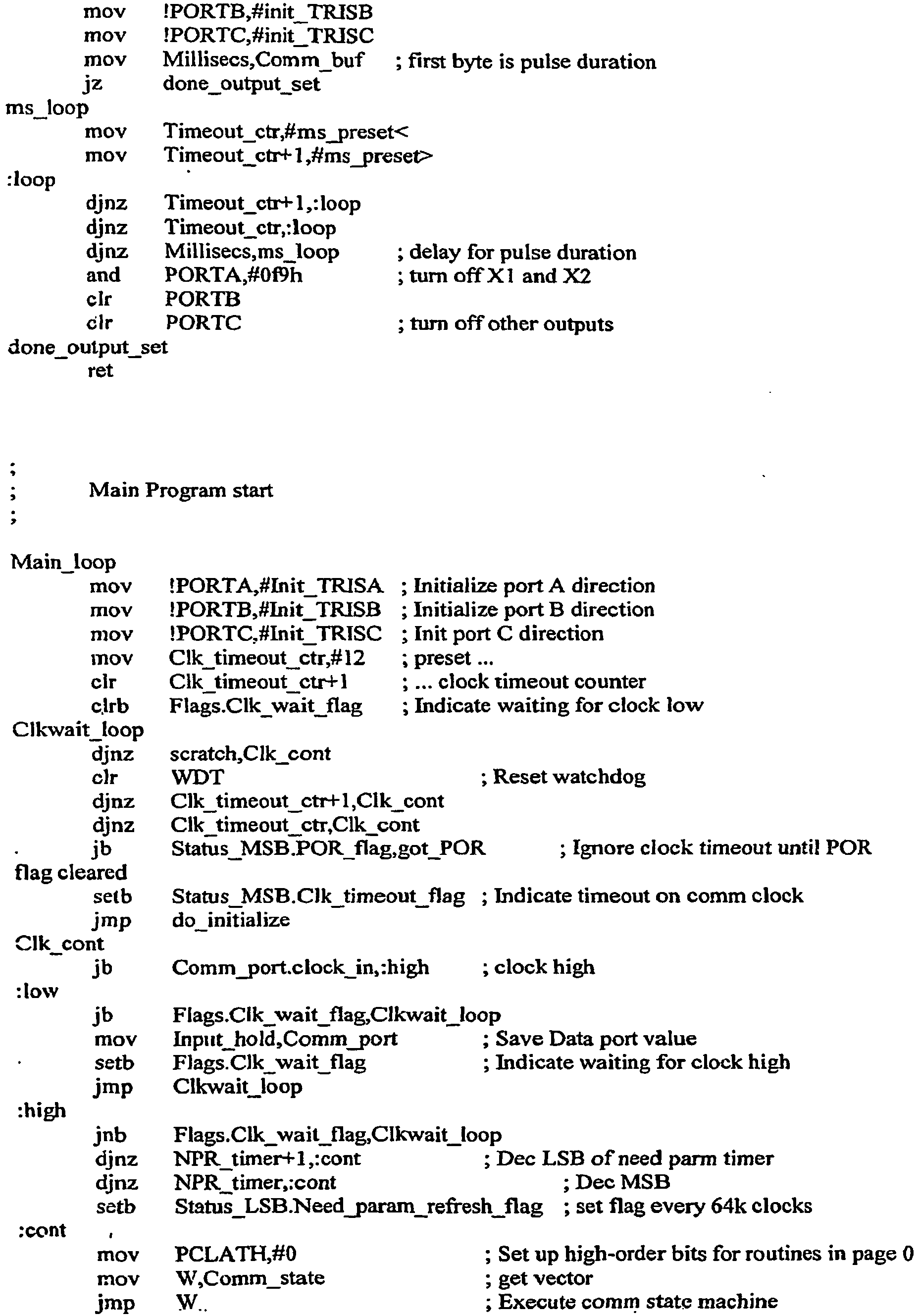
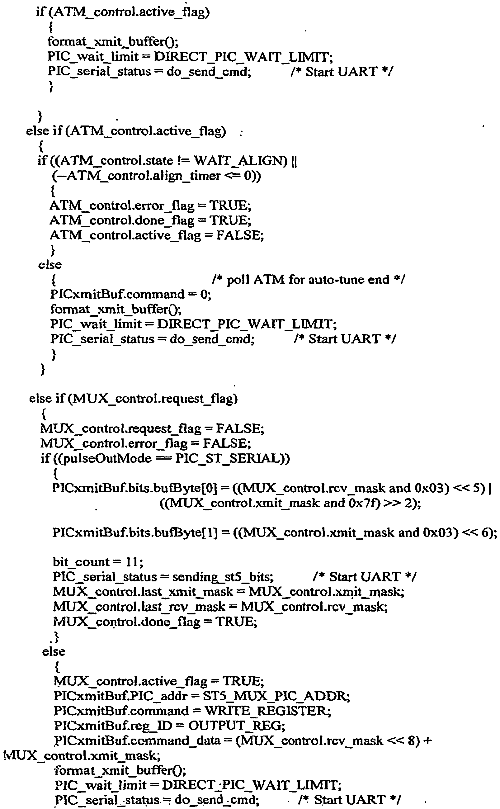
- the software additions include code modules that communicate with the added hardware, as described in the tables below.
- FIG. 1 is a block diagram of connections of a preferred embodiment.
- Medium voltage power lines A, B, C, and N feed into Distribution Transformer 110.
- Low voltage lines connect (via current transformers 120) Distribution Transformer 110 to Energy Guard unit 140.
- Energy Guard unit 140 monitors current transformers 120, and feeds single phase customer lines 1-24.
- FIG. 2 is a block diagram of preferred structure of an Energy Guard unit 140.
- Scan Transponder 210 is the preferred data collector for the unit 140, may be located external to or inside the MiniCloset, and may be the main data collector for more than one MiniCloset at a time.
- the Scan Transponder 210 preferably : (a) verifies data (each communication preferably begins with clock and meter identity verification to ensure data integrity); (b) collects data (periodically it collects a data block from each meter unit, with each block containing previously collected meter readings, interval readings, and event logs); (c) stores data (preferably the data is stored in non-volatile memory for a specified period (e.g., 40 days)); and (d) reports data (either via PLC, telephone modem, RS-232 connection, or other means).
- the slide plate 280 comprises a Minicloset meter head and a load control module 240 that provides the control signals to activate the relays. All of the electronics preferably is powered up by power supply 250.
- the back plate assembly 270 comprises multiple (e.g., 24) Current Transformers and relays - grouped, in this example, as three sets of 8 CTs and relays. Customer cables are wired through the CTs and connect to the circuit on customer premises 290.
- the remotely located Scan Transponder 210 accesses the Energy Guard meter head and bi-directionally communicates using power line carrier communication.
- the signal flow shown in FIGS. 1 and 2 preferably is accomplished by implementing different software code modules that work concurrently to enable remote connect/disconnect ability in the Minicloset.
- These software modules are: Code Module Location Function lcm.def and pic.def Load Control Module Actuate connect and disconnect of relays. pulse.c and pulse.h Meter Head Establish communication with LCM. picend.def and picvars.def Meter Head Provide control signals to LCM. pulselink.def and pulseoutm.c Meter Head Provides LCM with pulses to be used for connecting and disconnecting relays.
- FIGS. 3-10 are schematics of preferred components, as described below.
- the preferred connect/disconnect relays are series K850 KG relays, but those skilled in the art will recognize that other relays may be used without departing from the scope of the invention.
- Figure Schematic Detail 3 PCB 107D CPU board of the Scan Transponder and MiniCloset 4
- 5 PCB 144C Power Supply for MiniCloset 6
- This board brings back the Current Transformer information back to MiniCloset meter head.
- 7 160A Board for Load Control Module.
- 8 PCB 170 EG power supply board that adds capability for optical tamper detection.
- 9 PCB 171 EG Connection board. A board with traces to route the signal.
- 10 PCB 172 Control circuitry board for Relay control.
- the implementation of Energy Guard takes advantage of the similarity of architecture of traditional circuit breaker panels, with the multichannel metering environment.
- electricity is fed to the panel and distributed among various customer circuits via circuit breakers that provide the ability to connect or disconnect the customer circuits.
- MiniCloset/Energy Guard multiple current transformers measure the current in customer circuits and bring this data back to a central processing unit where the metering quantities are calculated.
- the MiniCloset/Energy Guard has several key differences with a circuit breaker panel. For example, whereas circuit breakers are found near customer premises, the Energy Guard typically is installed near the utility distribution transformer. The advantages offered by this alternate embodiment will be apparent to those skilled in the art. For example, this embodiment offers improved dimensions and overall size over the embodiments discussed above. Space is always a constraint when equipment additions are made to existing electrical installations.
- This version of the Energy Guard (“EG”) with preferred dimensions of 28" X 22" X 11" provides a substantial advantage in situations where volumetric constraints exist.
- this embodiment is operable to providing remote disconnect/connect operations, preventing theft, detecting tampering, detecting reverse voltage, performing pre-payment and limiting load, and performing meter validation.
- primary components of the EG are :
- the EG base comprises an enclosure bottom with screws and retaining washers as a locking mechanism for the top cover of EG, which is connected on one side by piano hinges. See FIG. 11 .
- the enclosure bottom provides routing for the customer cables.
- Three aluminum phase bus bars are placed towards the center of the Energy Guard assembly and staggered. See FIGS. 12 and 13 . These provide connection to the customer metering modules by the use of transition bars. A staggered bus bar layout is depicted in FIG. 13 . Bus bars are shown in black.
- the EG preferably comprises 4 neutral bars that form a frame for EG assembly, thereby providing a path for the neutral current. This is shown in FIG. 14 .
- the lug on the cross bar provides the neutral feed from the utility distribution transformer.
- transition bars complete the mechanical and electrical connection between the customer metering modules and the phase bus bars. See FIG. 15 .
- a transition bar for phase A and C is shown in FIG. 15A ; a transition bar for phase B is shown in FIG. 15B .
- FIG. 16 shows the transition bars in black.
- An acceptor module preferably is made of plastic and mechanically accepts the metering modules that can be easily fitted in the EG assembly.
- Each EG has 4 acceptor modules that are stacked together and can accommodate either 12 two-phase or 8 three-phase metering modules. See FIG. 17 .
- the acceptor module also provides a mechanical route for the motherboard neutral bar which connects to the control module. See FIG. 18 .
- Preferred customer metering modules provide metrology required to measure the consumption for a single phase, two phase, or three phase customer.
- An individual module functions as a complete stand-alone meter that can be tested and evaluated as a separate metering unit.
- Each module preferably comprises an integrated current sensing and relay module and metrology electronics, and provides a connection between the customer circuit and the phase bus bars.
- FIG. 19 depicts a preferred integrated current sensing and relay module.
- FIG. 20 depicts an exploded view of a preferred integrated current sensing and relay module.
- FIG. 21 shows exploded views of preferred metering modules.
- FIG. 22 shows the metering modules (shown in black) placed in the EG frame assembly and acceptor module.
- FIG. 23 shows an exploded view of Energy Guard
- FIG. 24 shows an exploded view of a preferred EG Assembly and EG Base Assembly.
- the Control Module boxes preferably comprise various PCBs that work concurrently to collect metering data from the individual metering modules and communicate over power lines to transmit this data to a master device, such as a Scan Transponder ("ST").
- ST Scan Transponder
- FIG. 25 shows a preferred Energy Guard layout for this embodiment.
- Each customer line has a corresponding Metering Module (PCB 203 and PCB 204, discussed below) (schematics shown in FIGS. 26 and 27 ).
- PCB 203 and PCB 204 discussed below
- a Back Place Board 2510 shown in FIG. 25 (PCB 234; see FIG. 28 for construction diagram and schematic) is the common bus that routes signals within the EG.
- the Control Module 2520 comprises a Power Board (PCB 210; see FIG. 29 for schematic) is the power supply board that also has the PLC transmit and receive circuitry on it.
- the Power Board provides power to the CPU board and the electronics of 203 boards.
- the Control Module 2520 also comprises an I/O Extension Board (PCB 230; see FIG. 30 for schematic) is a board with several I/O extension options that enable communication from Metering Modules to the CPU board.
- Control Module 2520 also comprises a CPU Board (PCB 202; see FIG. 31 for schematic), which has a Digital Signal Processing (DSP) processor on board.
- PCB 202 see FIG. 31 for schematic
- DSP Digital Signal Processing
- Control Module 2520 comprises a routing board (PCB 235; see FIG. 32 for schematic) with traces and a header with no electronic components on it.
- PCB 235 routing board
- Each Customer Display Module (CDM) 2530 is installed at the customer's premises and can bidirectionally communicate with the EG installed at the distribution transformer serving the customer.
- Two-way PLC enables utility-customer communication over low voltage power lines and allows the utility to send regular information, warnings, special information about outages, etc. to the customer.
- Each CDM 2530 comprises a selected combination of metering and power supply along with PLC circuitry on the same board (PCB 240; see FIG. 33 for schematic).
- Each CDM preferably also has a 9-digit display board (PCB 220; see FIG. 34 for schematic). This display communicates with EG and shows information about consumption, cautions, warnings, and other utility messages.
- the Energy Guard implements Fast Fourier Transform (FFT) on the PLC communication signal both at the ST and the meter, and for metering purposes performs detailed harmonic analysis.
- FFT Fast Fourier Transform
- the Control Module 2520 comprises power supply and PLC circuitry (PCB 210; see FIGS. 25 and 29 ); I/O extension (PCB 230; see FIG. 30 ) and CPU board named D Meter (PCB 202; see FIG. 31 ).
- the power supply supplies power to the D meter and I/O extension and contains the PLC transmitter and receiver circuitry.
- PCB 235 provides a trace routing and header connection between various boards.
- the Metering Module may have two versions: 2-phase or 3-phase.
- the 2-phase version can be programmed by software to function as a single 2-phase meter or two 1-phase meters.
- the 2-phase version comprises a B2 meter (PCB 203 schematic shown in FIG. 26 ), whereas the 3-phase version comprises a B3 meter (PCB204 schematic shown in FIG. 27 ).
- the B meters act as slaves to the D meter in Control Module 2520.
- the D and B meters can communicate via a serial ASCII protocol.
- the various B meters are interconnected via BPB 2510 to 2520 that provides power, a J Hz reference and serial communications to the D meter.
- the preferred DSP engine for the B meter is the Freescale 56F8014VFAE chip.
- the preferred microprocessor used for implementing the CPU on the D meter is one among the family of ColdFire Integrated Microprocessors, MCF5207.
- the use of a specific processor is determined by RAM and Flash requirements dictated by the meter version.
- a separate power supply and LCD board complete the electronic portion of the D meter as a product.
- the D meter is also a 3-phase meter and measures the total transformer output on which the EG is installed. As an anti-theft feature, this total is compared with the total consumption reported by the various B meters.
- the signal streams constituency is as follows:
- Each stream has an associated circuit to effect analog amplification and anti-aliasing.
- D meter Specific to the D meter is the preferred implementation of:
- Each metering and communication channel preferably comprises front-end analog circuitry followed by the signal processing.
- Unique to the analog circuitry is an anti-aliasing filter with fixed gain which provides first-order temperature tracking, hence eliminating the need to recalibrate meters when temperature drifts are encountered. This is discussed next, and then a preferred signal processing implementation is discussed.
- the analog front-end for voltage (current) channels comprises voltage (current) sensing elements and a programmable attenuator, followed by an anti-aliasing filter.
- the attenuator reduces the incoming signal level so that no clipping occurs after the anti-aliasing filter.
- the constant gain anti-aliasing filter restores the signal to full value at the input of the Analog to Digital Converter (ADC).
- ADC Analog to Digital Converter
- the anti-aliasing filter cuts off frequencies above 5 kHz. The inputs are then fed into the ADC which is a part of the DSP. See FIG. 35 , which is a block diagram of a preferred analog front-end for metering.
- a typical implementation would include a Programmable Gain Amplifier (PGA) followed by a low gain anti-aliasing filter
- the invention implements a programmable attenuator followed by a large fixed-gain filter.
- the implementation of both the anti-aliasing filters on a single chip is the same using the same Quad Op Amps along with 25 ppm resistors and NPO/COG capacitors.
- This unique implementation by pairing the anti-aliasing filters ensures that the phase drifts encountered in both voltage and current channels are exactly identical and hence accuracy of the power calculation (given by the product of V and I) is not compromised. This provides a means for both V and I channels to track temperature drifts up to first order without recalibrating the meter.
- FIG. 36 is a block diagram of the PCB 202 board; the functions of each block will be apparent to those skilled in the art.
- FIG. 36 shows a preferred DSP implementation.
- This embodiment preferably uses a PLL to lock the sampling of the signal streams to a multiple of the incoming A/C line frequency.
- the sampling is at a rate asynchronous to the power line.
- the VCO In the D meter, there is a VCO at 90-100 MHz which is controlled by the DSP engine via two PWM modules.
- the VCO directly drives the system clock of the DSP chip (disabling the internal PLL), so the DSP becomes an integral part of the PLL. Locking the system clock of the DSP to the power line facilitates the alignment of the sampling to the waveform of the power line.
- the phase detector should function so as to respond only to the fundamental of the incoming 60Hz wave and not to it harmonics.
- FIG. 37 is a block diagram of this preferred DSP implementation.
- a DSP BIOS or voluntary context switching code provides three stacks, each for background, PLC communications and serial communications.
- the small micro communicates with the DSP using a I2C driver.
- the MSP430F2002 integrated circuit measures the power supplies, tamper port, temperature and battery voltage.
- the tasks of the MSP430F2002 include:
- a typical installation consists of multiple EGs and STs communicating over the power lines.
- the D meter communicates bi-directionally with a remotely located Scan Transponder through the distribution transformer.
- This embodiment uses a 10-25 kHz band for PLC communication.
- the PLC signal is sampled at about 240 kHz (212 * 60), synchronous with line voltage, following which a Finite Impulse Response (FIR) filter is applied to decimate the data.
- FIR Finite Impulse Response
- Preferred FIR specifications are given below: 10-25 kHz Band Number of Taps 65 Stop Band Attenuation 71.23dB Pass band Upper Freq 25kHz Stop band Lower Freq 35kHz Sampled in 60 * 4096 Sample Out 30* 2048
- a 2048-point FFT is then performed on the decimated data.
- the data rate is thus determined to be 30 baud depending on the choice of FIR filters. Every FFT yields two bits approximately every 66 msec when using FIR in the 10-25 kHz band to communicate through distribution transformers.
- this embodiment preferably implements a unique technique for robust and reliable communication. This is done by injecting PLC signals at frequencies that are half odd harmonics of the line frequency (60Hz). This is discussed below, for an embodiment using a typical noise spectrum found on AC lines in the range 12-12.2 kHz.
- FIG. 39 illustrates injecting PLC signals at half-odd harmonics of 60 Hz. Since FFT is done every 30 Hz and the harmonics are separated by 60 Hz, the data bits reside in the bin corresponding to the 201.5th and 202.5th harmonic of 60 Hz in FIG. 39 . The algorithm considers these two bins of frequencies and compares the amplitude of the signal in the two to determine 1 or 0. This FSK scheme uses two frequencies and yields a data rate of 30 baud. Alternatively, QFSK, which uses 4 frequencies, can be implemented to yield 60 baud.
- both STs and D meters When traversing through transformers, both STs and D meters preferably perform FFT on the PLC and data signals every 30 Hz in a 10-25 kHZ range. Because the Phase Lock Loops (PLLs) implemented in both the ST and the D meter are locked to the line, the data frames are synchronized to the line frequency (60 Hz) as well. However, the data frames can shift in phase due to:
- the signal to noise ratio (SNR) is maximized when the meter data frame and ST data frames are aligned close to perfection. From a meter's standpoint, this requires receiving PLC signal from all possible STs that it can "hear,” decoding the signal, checking for SNR by aligning data frames, and then responding to the ST that is yielding maximum SNR.
- FIG. 40 depicts the 12 possible ways in which the FFT frame received by the meter can be out of phase with ST FFT frame. Dotted lines correspond to a 30 degree rotation accounting for a delta transformer in the signal path between ST and the meter.
- each frame of the ST there are an odd integral number of cycles of the carrier frequency. Since the preferred modulation scheme is Frequency Shift Keying (FSK), if there are n cycles for transmitting bit 1, bit 0 is transmitted using n+2 cycles of the carrier frequency. It becomes vital for the meter to recognize its own 2 cycles of 60 Hz in order to be able to decode its data bits which are available every 1/30th of a second.
- FSK Frequency Shift Keying
- the D meter decodes signals with misaligned data frames, there is energy that spills over into the adjacent (half-odd separated) frequencies. If the signal level that falls into the "adjacent" frequency bin is less than the noise floor, the signal can be decoded correctly. However, if the spill-over is more than the noise floor, the ability to distinguish between 1 and 0 decreases, and hence the overall SNR drops, resulting in an error in decoding.
- the meter then locks until a significant change in SNR ratio is encountered by the meter, in which case the process repeats.
- the D meter also is responsible for collecting the metering information from the various B meters via PCB 234.
- Each data stream in the meters has an associated circuit to effect analog amplification and anti-aliasing.
- Each of the analog front end sections has a programmable attenuator that is controlled by the higher level code.
- the data stream is sampled at 60 kHz (2 10 * 60) and then an FIR filter is applied to decimate the data stream to ⁇ 15 kHz (2 8 * 60). Preferred filter specifications are shown in the table below and FIG. 41 . Number of Taps 29 Stop Band Attenuation 80.453dB Pass band Upper Freq 3kHz Stop band Lower Freq 12kHz
- a 256-point complex FFT can be performed on every phase of the decimated data stream. This yields 2 pairs of data streams: a real part, which is the voltage, and an imaginary part, which is the current. This approach requires a 256 complex FFT every 16.667 milliseconds.
- V m,n denotes the m th harmonic of the n th cycle number.
- V 11 and I 11 correspond to the fundamental of the first cycle
- V 21 and I 21 to the first harmonic of the first cycle, etc., as shown in FIG. 42 , which depicts FFT frames for voltage, indicating the harmonics.
- the imaginary part of voltage is the measure of lack of synchronization between the PLL and the line frequency.
- the calculations are done in the time domain.
- the FFT functionality offers the flexibility to calculate metering quantities either using only the fundamental or including the harmonics.
- THD Total Harmonic Distortion
- the customer display module is installed at the customer premises, communicates with Energy Guard near the transformer, and comprises: PCB 240, power supply and PLC circuitry (see FIG. 33 ); and PCB 220, LCD display (see FIG. 34 ).
- the customer display unit installed at customers residence is a bidirectiorod PLC unit that communicates with EG. For example, not only can the utility send messages, the customer can also request a consumption verification with the EG installed at the pole.
Landscapes
- Engineering & Computer Science (AREA)
- Computer Networks & Wireless Communication (AREA)
- Power Engineering (AREA)
- Physics & Mathematics (AREA)
- General Physics & Mathematics (AREA)
- Arrangements For Transmission Of Measured Signals (AREA)
- Remote Monitoring And Control Of Power-Distribution Networks (AREA)
- Selective Calling Equipment (AREA)
- Measuring And Recording Apparatus For Diagnosis (AREA)
Description
- This application claims the priority of
U.S. Provisional Patent Application No. 60/737,580, filed November 15, 2005 U.S. Provisional Patent Application No. 60/739,375, filed November 23, 2005 U.S. Provisional Application No. 60/813,901, filed June 15, 2006 U.S. Pat. App. No. 11/431,849, filed May 9, 2006 U.S. Pat App. No. 11/030,417, filed January 6,2005 (nowU.S. Pat. No. 7,054,770 ), which is a divisional ofU.S. Pat. App. No. 09/795,838, filed February 28, 2001 U.S. Pat. No. 6,947,854 ). -
US 5696501 relates to an electrical metering device and a method therefor. The apparatus has a common node and a number of electrical metering devices connected to the node. The metering devices measure power consumption and transmit a signal indicative thereof to the node. The node calculates the power consumed and stores the results in a register. -
EP 1379012 relates to an automated and integrated meter reading procedure and transfer of obtained digital data to a remote computer system and an apparatus therefor. The apparatus measures power, gas, and water usage, processes the measured data, and transmits the data to a utility company substation. -
US 2005/0137813 relates to a system and method for on-line monitoring and billing of power consumption. The system has a metering device connected to a power line and a transponder connected to the metering device. The transponder receives and transmits data from and to the metering device via the power line, and receives and transmits data from and to a remotely located computer. - In accordance with the invention, there is provided an apparatus for multi-channel metering of electricity as recited in
claim 1. - One embodiment of the present invention comprises a metering device that is related to the Quadlogic ASIC-based family of meters (see
U.S. Pat. No. 6,947,854 , andU.S. Pat. App. Pub. No. 20060036388 ). Specifically, this embodiment (referred to herein for convenience as "Energy Guard") is a multi-channel meter that preferably is capable of providing much of the functionality of the above-mentioned family of meters, and further provides the improvements, features, and components listed below. - Used in at least one embodiment, a MiniCloset is a 24-channel metering device that can measure electric usage for up to 24 single-phase customers, 12 two-phase customer, or 8 three-phase customers. Preferably connected to the MiniCloset are one or more Load Control Modules (LCMs), discussed below.
- Energy Guard preferably comprises a MiniCloset meter head module and two LCMs mounted into a steel box. Relays that allow for an electricity customer to be remotely disconnected and reconnected, along with current transformers, also are mounted into the box. See
FIG. 1 . - Upon installation, an electricity customer's electricity supply line is tapped off the main electric feeder, passed through the Energy Guard apparatus, and run directly to the customer's home. The construction and usage of the Energy Guard will be
- apparent to those skilled in the art upon review of the description below and related figures. Source code is supplied in the attached Appendix.
- Energy Guard meters preferably are operable to provide:
- (A) Remote Disconnect/Reconnect: The meter supports full duplex (bidirectional) communication via power line communication ("PLC") and may be equipped with remotely operated relays (60 amp, 100 amp, or 200 amp) that allow for disconnect and reconnect of electric users remotely.
- (B) Theft Prevention: The system is designed with three specific features to prevent theft. First, an Energy Guard apparatus preferably is installed on a utility pole above the medium-tension lines, making it difficult for customers to reach and tamper with. Second, because there are no additional signal wires with the system (i.e., all communication is via the power line), any severed communication wires are immediately detectable. That is, if a communication wire is cut, service is cut, which is readily apparent. A third theft prevention feature is that the meter may be used to measure the transformer energy in order to validate the measured totals of individual clients. Discrepancies can indicate theft of power.
- (C) Tamper Detection: The Energy Guard preferably provides two modes of optical tamper detection. Each unit contains a light that reflects against a small mirror-like adhesive sticker. The absence of this reflective light indicates that the box has been opened. This detection will automatically disconnect all clients measured by that Energy Guard unit. In addition, if the Energy Guard enclosure is opened and ambient light enters, this will also automatically disconnect all clients measured by that Energy Guard unit. These two modes of tamper detection are continuously engaged and alternate multiple times per second for maximum security.
- (D) Reverse Voltage Detection: In some cases, a utility company can disconnect power to an individual client and that client is able to obtain power via an alternative feed. If the utility were to reconnect power under these conditions, damage could occur to the metering equipment and/or the distribution system. Energy Guard preferably is able to detect this fault condition. The Energy Guard can detect any voltage that feeds back into the open disconnect through the lines that connect to the customers' premises. If voltage is detected, the firmware of the Energy Guard will automatically prevent the reconnection.
- (E) Pre-Payment: Pre-payment for energy can be done via phone, electronic transaction, or in person. The amount of kWh purchased is transmitted to the meter and stored in its memory. The meter will count down, showing how much energy is still available before reaching zero and disconnecting. As long as the customer continues to purchase energy, there will be no interruption in service, and the utility company will have a daily activity report.
- (F) Load Limiting: As an alternative to disconnection for nonpayment or part of a pre-payment system, Energy Guard meters can allow the utility to remotely limit the power delivered to a set level, disconnecting when that load is exceeded. If the customer exceeds that load and is disconnected, the customer can reset a button on the optional remote display unit to restore load as long as the connected load is less than the pre-set limit. Alternatively, clients can call an electric utility service line by telephone to have the service restored. This feature allows electric utilities to provide electricity for critical systems even, for example, in the case of a non-paying customer.
- (G) Monthly Consumption Limiting: Some customers benefit from subsidized rates and are given a maximum total consumption per month. The Energy Guard firmware is capable of shutting down power when a certain consumption level is reached. However, this type of program is best implemented when advanced notification to customers is provided. This can be achieved either with a display in the home whereby a message or series of messages notifies customers that their rate of consumption is approaching the projected consumption for the month. Alternatively (or in conjunction) timed service interruptions can be programmed so that as the limit is approaching, power is disconnected for periods of time with longer and longer increments to notify the residents. These planned interruptions in service act as a warning to customers that their limit is nearing so that they have time to alter their consumption patterns.
- (H) Meter Validation: The integrated module of the system preferably is removable. This permits easy laboratory re-validation of meter accuracy in the event of client billing disputes.
- (I) Operational Benefits for Utility: The Energy Guard has extensive onboard event logs and diagnostic functions, providing field technicians with a wealth of data for commissioning and trouble shooting the electrical and communication systems. Non billing parameters include: amps, volts, temperature, total harmonic distortion, frequency, instantaneous values of watts, vars and volt-amperes, V2 hrs, 12 hrs, power factor, and phase angle.
- These features and others will be apparent to those skilled in the art after reviewing the attached descriptions, software code, and schematics.
- In one aspect, the invention comprises a device for measuring electricity usage, comprising: means for remote disconnection via power line communication; means for detection of electricity theft; means for tamper detection; and means for reverse voltage detection.
- In another aspect, the invention comprises an apparatus for multi-channel metering of electricity, comprising: (a) a meter head operable to measure electricity usage for a plurality of electricity consumer lines; (b) a transponder in communication with the meter head and operable to transmit data received from the meter head via power line communication to a remotely located computer, and to transmit data received via power line communication from the remotely located computer to the meter head; and (c) a load control module in communication with the meter head and operable to actuate connection and disconnection of each of a plurality of relays, each relay of the plurality of relays corresponding to one of the plurality of electricity consumer lines.
- In various embodiments: (1) the apparatus further comprises a tamper detector in communication with the meter head; (2) the tamper detector comprises a light and a reflective surface, and the meter head is operable to instruct the load control module to disconnect all of the customer lines if the tamper detector provides notification that the light is not detected reflecting from the reflective surface; (3) the apparatus further comprises a box containing the meter head, the load control module, and the relays, and wherein the tamper detector comprises a detector of ambient light entering the box; (4) the apparatus further comprises a box containing the meter head, the load control module, and the relays, and wherein the box is installed on a utility pole; (5) the apparatus further comprises means for comparing transformer energy to total energy used by the consumer lines; (6) the apparatus further comprises means for detecting reverse voltage flow through the consumer lines; (7) the apparatus further comprises a computer readable memory in communication with the meter head and a counter in communication with the meter head, the counter corresponding to a customer line and operable to count down an amount of energy stored in the memory, and the meter head operable to send a disconnect signal to the load control module to disconnect the customer line when the counter reaches zero; (8) the apparatus further comprises a computer readable memory in communication with the meter head, the memory operable to store a load limit for a customer line, and the meter head operable to send a disconnect signal to the load control module to disconnect the customer line when the load limit is exceeded; (9) the apparatus further comprises a computer readable memory in communication with the meter head, the memory operable to store a usage limit for a customer line, and the meter head operable to send a disconnect signal to the load control module to disconnect the customer line when the usage limit is exceeded; (10) the transponder is operable to communicate with the remotely located computer over medium tension power lines; (11) the apparatus further comprises a display unit in communication with the meter head and operable to display data received from the meter head; (12) the display unit is operable to display information regarding a customer's energy consumption; (13) the display unit is operable to display warnings regarding a customer's energy usage or suspected theft of energy; and (14) the display unit is operable to transmit to said meter head information entered by a customer.
-
-
FIG. 1 is a block/wiring diagram showing connection of preferred embodiments. -
FIG. 2 is a block diagram showing physical configuration of preferred embodiments. -
FIGS. 3A-3B are schematic diagrams of a preferred CPU board of a Scan Transponder and MiniCloset. -
FIG. 4 is a schematic diagram of a preferred Scan Transponder power supply. -
FIG. 5 is a schematic diagram of a preferred MiniCloset power supply. -
FIG. 6 is a schematic diagram of a preferred circuit board for returning current transformer information to a MiniCloset meter head. -
FIGS. 7A-7C are schematic diagrams of a preferred Load Control Module circuit board. -
FIGS. 8A-8D are schematic diagrams of a preferred power supply board that provides for optical tamper detection. -
FIGS. 9A-9C are schematic diagrams of a preferred Energy Guard connection board. -
FIG. 10 is a schematic diagram for a control circuitry board operable to provide relay control. -
FIG. 11 is a diagram of preferred Energy Guard base assembly.FIGS. 12 and13 are diagrams of preferred phase bus bars and construction of same. -
FIG. 14 is a diagram depicting preferred neutral bar frame construction and assembly. -
FIG. 15 depicts preferred transition bars;FIG. 16 depicts preferred placement of transition bars. -
FIGS. 17 and depict preferred acceptor module constructiono. -
FIG. 19 depicts a preferred integrated current sensing and relay module.FIG. 20 depicts an exploded view of a preferred integrated current sensing and relay module. -
FIG. 21 shows exploded views of preferred metering modules. -
FIG. 22 shows the metering modules placed in an EG frame assembly and acceptor module. -
FIG. 23 shows an exploded view a preferred embodiment of Energy Guard.FIG. 24 shows an exploded view of a preferred EG assembly and base assembly. -
FIG. 25 shows a preferred EG layout. -
FIGS. 26 and27 are preferred metering module schematics. -
FIG. 28 has preferred schematics for a back place board. -
FIG. 29 has preferred schematics for a power board. -
FIG. 30 has preferred schematics for an I/O extension board. -
FIG. 31 has preferred schematics for a CPU board. -
FIG. 32 has preferred schematics for a control module. -
FIG. 33 has preferred schematics for metering and power supply circuitry for a customer display module;FIG. 34 has preferred schematics for a display board for the CDM. -
FIG. 35 is a block diagram of a preferred analog front end for metering.FIGS. 36 and37 depict preferred DSP implementations. -
FIG. 38 illustrates preferred in-phase filter frequency and implulse response characteristics. -
FIG. 39 illustrates injecting PLC signals at half-odd harmonics of 60 Hz.FIG. 40 depicts 12 possible ways in which an FFT frame received by a meter can be out of phase with a scan transponded FFT frame. -
FIG. 41 illustrates preferred FIR filter specifications. -
FIG. 42 depicts voltage and current resulting from a preferred FFT. - In one embodiment, an Energy Guard metering apparatus comprises a MiniCloset (that is, a metering apparatus operable to meter a plurality of customer lines); a Scan Transponder; one or more relays operable to disconnect service to selected customers; a Load Control Module; and optical tamper detection means.
- The MiniCloset and Scan Transponder referred to herein are largely the same as described in
U.S. Pat. No. 6,947,854 . That is, although each has been improved over the years, the functionality and structure relevant to this description may be taken to be the same as described in that patent. - One aspect of the invention comprises taking existing multichannel metering functionality found in the MiniCloset and adding remote connect and disconnect via PLC. Providing such additional functionality required adding new hardware and software. The added hardware comprises a Load Control Module (LCM) and
- connect/disconnect relays. Also added was support circuitry to route signal traces to and from the main meter processor- the MiniCloset5 Meter Head. The software additions include code modules that communicate with the added hardware, as described in the tables below.
-
FIG. 1 is a block diagram of connections of a preferred embodiment. Medium voltage power lines A, B, C, and N (neutral) feed intoDistribution Transformer 110. Low voltage lines connect (via current transformers 120)Distribution Transformer 110 toEnergy Guard unit 140.Energy Guard unit 140 monitorscurrent transformers 120, and feeds single phase customer lines 1-24. -
FIG. 2 is a block diagram of preferred structure of anEnergy Guard unit 140. -
Scan Transponder 210 is the preferred data collector for theunit 140, may be located external to or inside the MiniCloset, and may be the main data collector for more than one MiniCloset at a time. TheScan Transponder 210 preferably : (a) verifies data (each communication preferably begins with clock and meter identity verification to ensure data integrity); (b) collects data (periodically it collects a data block from each meter unit, with each block containing previously collected meter readings, interval readings, and event logs); (c) stores data (preferably the data is stored in non-volatile memory for a specified period (e.g., 40 days)); and (d) reports data (either via PLC, telephone modem, RS-232 connection, or other means). - The
slide plate 280 comprises a Minicloset meter head and aload control module 240 that provides the control signals to activate the relays. All of the electronics preferably is powered up bypower supply 250. Theback plate assembly 270 comprises multiple (e.g., 24) Current Transformers and relays - grouped, in this example, as three sets of 8 CTs and relays. Customer cables are wired through the CTs and connect to the circuit oncustomer premises 290. The remotely locatedScan Transponder 210 accesses the Energy Guard meter head and bi-directionally communicates using power line carrier communication. - The signal flow shown in
FIGS. 1 and2 preferably is accomplished by implementing different software code modules that work concurrently to enable remote connect/disconnect ability in the Minicloset. These software modules, provided in the Appendix below, are:Code Module Location Function lcm.def and pic.def Load Control Module Actuate connect and disconnect of relays. pulse.c and pulse.h Meter Head Establish communication with LCM. picend.def and picvars.def Meter Head Provide control signals to LCM. pulselink.def and pulseoutm.c Meter Head Provides LCM with pulses to be used for connecting and disconnecting relays. -
FIGS. 3-10 are schematics of preferred components, as described below. The preferred connect/disconnect relays are series K850 KG relays, but those skilled in the art will recognize that other relays may be used without departing from the scope of the invention.Figure Schematic Detail 3 PCB 107D CPU board of the Scan Transponder and MiniCloset 4 PCB 135C Power Supply for Scan Transponder. 5 PCB 144C Power Supply for MiniCloset 6 PCB 146C This board brings back the Current Transformer information back to MiniCloset meter head. 7 PCB 160A Board for Load Control Module. 8 PCB 170 EG power supply board that adds capability for optical tamper detection. 9 PCB 171 EG Connection board. A board with traces to route the signal. 10 PCB 172 Control circuitry board for Relay control. - In another embodiment, the implementation of Energy Guard takes advantage of the similarity of architecture of traditional circuit breaker panels, with the multichannel metering environment. In a circuit breaker panel, electricity is fed to the panel and distributed among various customer circuits via circuit breakers that provide the ability to connect or disconnect the customer circuits.
- In the MiniCloset/Energy Guard, multiple current transformers measure the current in customer circuits and bring this data back to a central processing unit where the metering quantities are calculated. However, the MiniCloset/Energy Guard has several key differences with a circuit breaker panel. For example, whereas circuit breakers are found near customer premises, the Energy Guard typically is installed near the utility distribution transformer. The advantages offered by this alternate embodiment will be apparent to those skilled in the art. For example, this embodiment offers improved dimensions and overall size over the embodiments discussed above. Space is always a constraint when equipment additions are made to existing electrical installations. This version of the Energy Guard ("EG"), with preferred dimensions of 28"
X 22"X 11" provides a substantial advantage in situations where volumetric constraints exist. - The following description includes preferred construction details, detailed schematics, and software descriptions. As with the embodiments discussed above, this embodiment is operable to providing remote disconnect/connect operations, preventing theft, detecting tampering, detecting reverse voltage, performing pre-payment and limiting load, and performing meter validation.
- Preferred EG Construction Details
- In this embodiment, primary components of the EG are :
- 1. Energy Guard Base Assembly
- 2. Energy Guard Assembly
- a. Phase Bus Bars and Neutral Bars
- b. Transition Bars
- c. Acceptor Module
- 3. Energy Guard Metering Modules
- a. Metering Modules
- i. Integrated Current Sensing and Relay Modules
- a. Metering Modules
- 4. Energy Guard Electronics
- a.
PCB 203 - b.
PCB 204 - c.
PCB 234 - d. PCB 235
- e. PCB 202
- f.
PCB 210 - g.
PCB 230 - h. PCB 206
- a.
- The EG base comprises an enclosure bottom with screws and retaining washers as a locking mechanism for the top cover of EG, which is connected on one side by piano hinges. See
FIG. 11 . The enclosure bottom provides routing for the customer cables. - Three aluminum phase bus bars are placed towards the center of the Energy Guard assembly and staggered. See
FIGS. 12 and13 . These provide connection to the customer metering modules by the use of transition bars. A staggered bus bar layout is depicted inFIG. 13 . Bus bars are shown in black. - The EG preferably comprises 4 neutral bars that form a frame for EG assembly, thereby providing a path for the neutral current. This is shown in
FIG. 14 . The lug on the cross bar provides the neutral feed from the utility distribution transformer. Also, there are 2 mother board neutral bars that carry the neutral current to the control module. - The transition bars complete the mechanical and electrical connection between the customer metering modules and the phase bus bars. See
FIG. 15 . A transition bar for phase A and C is shown inFIG. 15A ; a transition bar for phase B is shown inFIG. 15B .FIG. 16 shows the transition bars in black. - An acceptor module preferably is made of plastic and mechanically accepts the metering modules that can be easily fitted in the EG assembly. Each EG has 4 acceptor modules that are stacked together and can accommodate either 12 two-phase or 8 three-phase metering modules. See
FIG. 17 . The acceptor module also provides a mechanical route for the motherboard neutral bar which connects to the control module. SeeFIG. 18 . - Preferred customer metering modules provide metrology required to measure the consumption for a single phase, two phase, or three phase customer. An individual module functions as a complete stand-alone meter that can be tested and evaluated as a separate metering unit. Each module preferably comprises an integrated current sensing and relay module and metrology electronics, and provides a connection between the customer circuit and the phase bus bars.
FIG. 19 depicts a preferred integrated current sensing and relay module.FIG. 20 depicts an exploded view of a preferred integrated current sensing and relay module. -
FIG. 21 shows exploded views of preferred metering modules.FIG. 22 shows the metering modules (shown in black) placed in the EG frame assembly and acceptor module. -
FIG. 23 shows an exploded view of Energy Guard, andFIG. 24 shows an exploded view of a preferred EG Assembly and EG Base Assembly. - The Control Module boxes preferably comprise various PCBs that work concurrently to collect metering data from the individual metering modules and communicate over power lines to transmit this data to a master device, such as a Scan Transponder ("ST").
-
FIG. 25 shows a preferred Energy Guard layout for this embodiment. Each customer line has a corresponding Metering Module (PCB 203 andPCB 204, discussed below) (schematics shown inFIGS. 26 and27 ). - A
Back Place Board 2510 shown inFIG. 25 (PCB 234; seeFIG. 28 for construction diagram and schematic) is the common bus that routes signals within the EG. There are two kinds of communication options on theBack Place Board 2510 to enable data transfer fromControl Module 2520 to individualMetering Modules PCB 203. This can be done either using the 2 wire I2C option or the 1 wire serial option. - The
Control Module 2520 comprises a Power Board (PCB 210; seeFIG. 29 for schematic) is the power supply board that also has the PLC transmit and receive circuitry on it. The Power Board provides power to the CPU board and the electronics of 203 boards. TheControl Module 2520 also comprises an I/O Extension Board (PCB 230; seeFIG. 30 for schematic) is a board with several I/O extension options that enable communication from Metering Modules to the CPU board. -
Control Module 2520 also comprises a CPU Board (PCB 202; seeFIG. 31 for schematic), which has a Digital Signal Processing (DSP) processor on board. - Finally,
Control Module 2520 comprises a routing board (PCB 235; seeFIG. 32 for schematic) with traces and a header with no electronic components on it. - Each Customer Display Module (CDM) 2530 is installed at the customer's premises and can bidirectionally communicate with the EG installed at the distribution transformer serving the customer. Two-way PLC enables utility-customer communication over low voltage power lines and allows the utility to send regular information, warnings, special information about outages, etc. to the customer.
- Each
CDM 2530 comprises a selected combination of metering and power supply along with PLC circuitry on the same board (PCB 240; seeFIG. 33 for schematic). Each CDM preferably also has a 9-digit display board (PCB 220; seeFIG. 34 for schematic). This display communicates with EG and shows information about consumption, cautions, warnings, and other utility messages. - In one embodiment, the Energy Guard implements Fast Fourier Transform (FFT) on the PLC communication signal both at the ST and the meter, and for metering purposes performs detailed harmonic analysis. This section discusses an implementation scheme of the Metering Modules, communication with Control Modules and PLC communication of the Control Module with a remotely located Scan Transponder.
- The
Control Module 2520 comprises power supply and PLC circuitry (PCB 210; seeFIGS. 25 and29 ); I/O extension (PCB 230; seeFIG. 30 ) and CPU board named D Meter (PCB 202; seeFIG. 31 ). The power supply supplies power to the D meter and I/O extension and contains the PLC transmitter and receiver circuitry. PCB 235 provides a trace routing and header connection between various boards. - The Metering Module may have two versions: 2-phase or 3-phase. The 2-phase version can be programmed by software to function as a single 2-phase meter or two 1-phase meters. The 2-phase version comprises a B2 meter (
PCB 203 schematic shown inFIG. 26 ), whereas the 3-phase version comprises a B3 meter (PCB204 schematic shown inFIG. 27 ). The B meters act as slaves to the D meter inControl Module 2520. The D and B meters can communicate via a serial ASCII protocol. The various B meters are interconnected viaBPB 2510 to 2520 that provides power, a J Hz reference and serial communications to the D meter. The preferred DSP engine for the B meter is the Freescale 56F8014VFAE chip. The preferred microprocessor used for implementing the CPU on the D meter is one among the family of ColdFire Integrated Microprocessors, MCF5207. The use of a specific processor is determined by RAM and Flash requirements dictated by the meter version. A separate power supply and LCD board complete the electronic portion of the D meter as a product. Apart from acting as a master for B meters, the D meter is also a 3-phase meter and measures the total transformer output on which the EG is installed. As an anti-theft feature, this total is compared with the total consumption reported by the various B meters.
- The signal streams constituency is as follows:
- B2: Two voltage, Two current, and No Power Line Carrier (PLC) Channel.
- B3: Three voltage, Three current, and No PLC Channel.
- D: Three voltage, Three current, and one PLC Channel.
- Each stream has an associated circuit to effect analog amplification and anti-aliasing.
- Specific to the D meter is the preferred implementation of:
- A Phase Locked Loop (PLL) to lock the sampling of the signal streams to a multiple of the incoming A/C line (synchronous sampling to the power line).
- A Voltage Controlled Oscillator (VCO) at 90-100 MHz controlled by DSP processor via two PWM modules directly driving the system clock hence making the DSP coherent with the PLL.
- A synchronous phase detector that responds only to the fundamental of the incoming line frequency wave and not to its harmonics.
- Option for performing FSK and PSK modulation schemes.
- Each metering and communication channel preferably comprises front-end analog circuitry followed by the signal processing. Unique to the analog circuitry is an anti-aliasing filter with fixed gain which provides first-order temperature tracking, hence eliminating the need to recalibrate meters when temperature drifts are encountered. This is discussed next, and then a preferred signal processing implementation is discussed.
- The analog front-end for voltage (current) channels comprises voltage (current) sensing elements and a programmable attenuator, followed by an anti-aliasing filter. The attenuator reduces the incoming signal level so that no clipping occurs after the anti-aliasing filter. The constant gain anti-aliasing filter restores the signal to full value at the input of the Analog to Digital Converter (ADC). For metering, the anti-aliasing filter cuts off frequencies above 5 kHz. The inputs are then fed into the ADC which is a part of the DSP. See
FIG. 35 , which is a block diagram of a preferred analog front-end for metering. - Whereas a typical implementation would include a Programmable Gain Amplifier (PGA) followed by a low gain anti-aliasing filter, the invention, in this embodiment, implements a programmable attenuator followed by a large fixed-gain filter. In addition, the implementation of both the anti-aliasing filters on a single chip is the same using the same Quad Op Amps along with 25 ppm resistors and NPO/COG capacitors. This unique implementation by pairing the anti-aliasing filters ensures that the phase drifts encountered in both voltage and current channels are exactly identical and hence accuracy of the power calculation (given by the product of V and I) is not compromised. This provides a means for both V and I channels to track temperature drifts up to first order without recalibrating the meter.
- In contrast, using a PGA along with a low gain filter cannot track the phase shift in the V and I signals introduced due to temperature. This is because the phase shift introduced by PGA is a function of the gain.
-
FIG. 36 is a block diagram of the PCB 202 board; the functions of each block will be apparent to those skilled in the art.FIG. 36 shows a preferred DSP implementation. - This embodiment preferably uses a PLL to lock the sampling of the signal streams to a multiple of the incoming A/C line frequency. In the embodiment discussed above, the sampling is at a rate asynchronous to the power line. In the D meter, there is a VCO at 90-100 MHz which is controlled by the DSP engine via two PWM modules. The VCO directly drives the system clock of the DSP chip (disabling the internal PLL), so the DSP becomes an integral part of the PLL. Locking the system clock of the DSP to the power line facilitates the alignment of the sampling to the waveform of the power line. The phase detector should function so as to respond only to the fundamental of the incoming 60Hz wave and not to it harmonics.
FIG. 37 is a block diagram of this preferred DSP implementation. - A DSP BIOS or voluntary context switching code provides three stacks, each for background, PLC communications and serial communications. The small micro communicates with the DSP using a I2C driver. The MSP430F2002 integrated circuit measures the power supplies, tamper port, temperature and battery voltage. The tasks of the MSP430F2002 include:
- i. maintain an RTC;
- ii. measure the battery voltage;
- iii. measure the temperature;
- iv. measure the +U power supply;
- v. reset the DSP on brown out;
- vi. provide an additional watchdog circuit; and
- vii. provide a 1-second reference to go into the DSP for a time reference to measure the 1-second reference against the system clock from the VCO.
- A typical installation consists of multiple EGs and STs communicating over the power lines. The D meter communicates bi-directionally with a remotely located Scan Transponder through the distribution transformer. To enable this, this embodiment uses a 10-25 kHz band for PLC communication. The PLC signal is sampled at about 240 kHz (212 * 60), synchronous with line voltage, following which a Finite Impulse Response (FIR) filter is applied to decimate the data. Preferred FIR specifications are given below:
10-25 kHz Band Number of Taps 65 Stop Band Attenuation 71.23dB Pass band Upper Freq 25kHz Stop band Lower Freq 35kHz Sampled in 60 * 4096 Sample Out 30* 2048 - See
FIG. 38 for preferred inphase filter frequency response and impulse response characteristics. - After the decimation is done to 60 kHz (211 * 30), a 2048-point FFT is then performed on the decimated data. The data rate is thus determined to be 30 baud depending on the choice of FIR filters. Every FFT yields two bits approximately every 66 msec when using FIR in the 10-25 kHz band to communicate through distribution transformers.
- To circumvent the problem of communicating in the presence of line noise, this embodiment preferably implements a unique technique for robust and reliable communication. This is done by injecting PLC signals at frequencies that are half odd harmonics of the line frequency (60Hz). This is discussed below, for an embodiment using a typical noise spectrum found on AC lines in the range 12-12.2 kHz.
-
FIG. 39 illustrates injecting PLC signals at half-odd harmonics of 60 Hz. Since FFT is done every 30 Hz and the harmonics are separated by 60 Hz, the data bits reside in the bin corresponding to the 201.5th and 202.5th harmonic of 60 Hz inFIG. 39 . The algorithm considers these two bins of frequencies and compares the amplitude of the signal in the two to determine 1 or 0. This FSK scheme uses two frequencies and yields a data rate of 30 baud. Alternatively, QFSK, which uses 4 frequencies, can be implemented to yield 60 baud. - When traversing through transformers, both STs and D meters preferably perform FFT on the PLC and data signals every 30 Hz in a 10-25 kHZ range. Because the Phase Lock Loops (PLLs) implemented in both the ST and the D meter are locked to the line, the data frames are synchronized to the line frequency (60 Hz) as well. However, the data frames can shift in phase due to:
- 1. various transformer configurations that can exist in the path between the ST and meter (delta-Wye, etc.); and
- 2. a shift in phase due to the fact that STs are locked on a particular phase, whereas single and polyphase meters can be powered up by other phases.
- The signal to noise ratio (SNR) is maximized when the meter data frame and ST data frames are aligned close to perfection. From a meter's standpoint, this requires receiving PLC signal from all possible STs that it can "hear," decoding the signal, checking for SNR by aligning data frames, and then responding to the ST that is yielding maximum SNR.
FIG. 40 depicts the 12 possible ways in which the FFT frame received by the meter can be out of phase with ST FFT frame. Dotted lines correspond to a 30 degree rotation accounting for a delta transformer in the signal path between ST and the meter. - In addition, because the data frames are available every 30 Hz on a 60 Hz line, there are two possibilities corresponding to the 2 possible phases obtained by dividing 60 Hz by 2. Hence, there are 24 ways that meter data frames can be misaligned with ST data frames.
- In each frame of the ST, there are an odd integral number of cycles of the carrier frequency. Since the preferred modulation scheme is Frequency Shift Keying (FSK), if there are n cycles for transmitting
bit 1,bit 0 is transmitted using n+2 cycles of the carrier frequency. It becomes vital for the meter to recognize its own 2 cycles of 60 Hz in order to be able to decode its data bits which are available every 1/30th of a second. - If the D meter decodes signals with misaligned data frames, there is energy that spills over into the adjacent (half-odd separated) frequencies. If the signal level that falls into the "adjacent" frequency bin is less than the noise floor, the signal can be decoded correctly. However, if the spill-over is more than the noise floor, the ability to distinguish between 1 and 0 decreases, and hence the overall SNR drops, resulting in an error in decoding. In conclusion:
- a. If the frames are misaligned, smearing of data bits occurs and the SNR degrades.
- b. In the event that the frequency changes and there are misaligned data frames, there is a substantial amount of energy that spills over into the adjacent FFT bins, hence interfering with the other STs in the system that communicate using frequencies in that specific bins.
- Once the clock shift is determined corresponding to the highest SNR, the meter then locks until a significant change in SNR ratio is encountered by the meter, in which case the process repeats.
- Whereas versions of the B meter and the D meter perform metering, the D meter also is responsible for collecting the metering information from the various B meters via
PCB 234. Each data stream in the meters has an associated circuit to effect analog amplification and anti-aliasing. Each of the analog front end sections has a programmable attenuator that is controlled by the higher level code. The data stream is sampled at 60 kHz (210 * 60) and then an FIR filter is applied to decimate the data stream to ~15 kHz (28 * 60). Preferred filter specifications are shown in the table below andFIG. 41 .Number of Taps 29 Stop Band Attenuation 80.453dB Pass band Upper Freq 3kHz Stop band Lower Freq 12kHz - Since only the data up to 3 kHz is of interest, praferably a 3-12 kHz roll off on the decimating FIR is used with ~15kHZ sample rate. The frequencies from 0-3 kHz or 12-15 kHz are mapped into 0-3 kHZ. A real FFTs is performed to yield 2 streams of data which can be further decomposed into 4 streams of data: Real and Imaginary Voltage and Real and Imaginary Current. This is achieved by adding and subtracting positive and negative mirror frequencies for the real and imaginary parts, respectively. Since the aliased signal in the 12-15 kHZ range falls below 80 dB, the accuracy is achieved using the above-discussed FIR filter. Alternatively, a 256-point complex FFT can be performed on every phase of the decimated data stream. This yields 2 pairs of data streams: a real part, which is the voltage, and an imaginary part, which is the current. This approach requires a 256 complex FFT every 16.667 milliseconds.
- The results of performing either FFT are the voltage and current shown in
FIG. 42 , where the notation Vm,n denotes the mth harmonic of the nth cycle number. For example, V11 and I11 correspond to the fundamental of the first cycle, and V21 and I21 to the first harmonic of the first cycle, etc., as shown inFIG. 42 , which depicts FFT frames for voltage, indicating the harmonics. - The real and imaginary parts of the harmonic content of any kth cycle are given by:


- The imaginary part of voltage is the measure of lack of synchronization between the PLL and the line frequency. In order to calculate metering quantities, the calculations are done in the time domain. In the time domain, the FFT functionality offers the flexibility to calculate metering quantities either using only the fundamental or including the harmonics. Using the complex form of voltage and current obtained from the FFT, the metering quantities are calculated as:


- However, in the above formulas, when the harmonics are included (Vmk & Imk ; m = 1...M, k =1...n), all metering quantities include the effects of harmonics. On the other hand, when only the fundamental is used (V lk & I lk ), all calculated quantities represent only the 60 Hz contribution. As an example, we show the calculations when only the fundamental is used to perform calculations. Only Vl and Il are used from all FFT data frames. The following quantities are calculated for a given set of N frames and a line frequency of fline :


- The displacement power factor is given by:


- This flexibility to either include or exclude the harmonics when calculating metering quantities translates to a significant improvement over the capabilities offered by the above-described embodiment Yet another feature offered by this embodiment is the calculation of Total Harmonic Distortion (THD). The THD is the measurement of the harmonic distortion present, and is defined as the ratio of the sum of the powers of all harmonic components to the power of the fundamental. For the nth cycle, this is evaluated as:


- The customer display module is installed at the customer premises, communicates with Energy Guard near the transformer, and comprises:
PCB 240, power supply and PLC circuitry (seeFIG. 33 ); andPCB 220, LCD display (seeFIG. 34 ). In one embodiment, the customer display unit installed at customers residence is a bidirectiorod PLC unit that communicates with EG. For example, not only can the utility send messages, the customer can also request a consumption verification with the EG installed at the pole. -






Claims (20)
- An apparatus for multi-channel metering of electricity, comprising:a meter head (140) located on a secondary side of a transformer (110),said meter head in communication with a transponder (210) located on a primary side of the transformer operable to transmit data to and receive data from said transponder via power line communication, said transponder operable to transmit data to and receive data from a remotely located computer;characterised in that:the meter head is operable to separately measure electricity usage for each of a plurality of electricity consumer lines; andthe apparatus further comprises:one or more load control modules (240) in communication with said meter head and operable to actuate connection and disconnection of each of a plurality of relays, each relay of said plurality of relays corresponding to one of said plurality of electricity consumer lines; anda box containing said meter head, said load control module, and said relays.
- An apparatus as in claim 1, further comprising a tamper detector in communication with said meter head (140).
- An apparatus as in claim 2, wherein said tamper detector comprises a light and a reflective surface, and wherein said meter head is operable to instruct said one or more load control modules (240) to disconnect all of said customer lines if said tamper detector provides notification that said light is not detected reflecting from said reflective surface.
- An apparatus as in claim 2, wherein said tamper detector comprises a detector of ambient light entering said box.
- An apparatus as in claim 1, wherein said box is installed on a utility pole.
- An apparatus as in claim 1, further comprising means for comparing transformer energy to total energy used by said consumer lines.
- An apparatus as in claim 1, further comprising means for detecting reverse voltage flow through said consumer lines.
- An apparatus as in claim 1, further comprising a computer readable memory in communication with said meter head (140) and a counter in communication with said meter head, said counter corresponding to a customer line and operable to count down an amount of energy stored in said memory, and said meter head operable to send a disconnect signal to a corresponding load control module (240) to disconnect said customer line when said counter reaches zero.
- An apparatus as in claim 1, further comprising a computer readable memory in communication with said meter head (140), said memory operable to store a load limit for a customer line, and said meter head operable to send a disconnect signal to a corresponding load control module to disconnect said customer line when said load limit is exceeded.
- An apparatus as in claim 1, further comprising a computer readable memory in communication with said meter head (140), said memory operable to store a usage limit for a customer line, and said meter head operable to send a disconnect signal to a corresponding load control module to disconnect said customer line when said usage limit is exceeded.
- An apparatus as in claim 1, wherein said transponder (210) is operable to communicate with said remotely located computer over medium tension power lines.
- An apparatus as in claim I, further comprising a display unit in communication with said meter head (140) and operable to display data received from said meter head.
- An apparatus as in claim 12, wherein said display unit is operable to display information regarding a customer's energy consumption.
- An apparatus as in claim 12, wherein said display unit is operable to display warnings regarding a customer's energy usage or suspected theft of energy.
- An apparatus as in claim 12, wherein said display unit is operable to transmit to said meter head information entered by a customer.
- An apparatus as in claim 1, wherein said transponder (210) is operable to report data to said remotely located computer via a telephone line.
- An apparatus as in claim 1, wherein said meter head (140) is operable to measure electricity supplied to said meter head.
- An apparatus as in claim 1, wherein said meter head (140) is operable to transmit data directly to said transponder (210) at frequencies within the range 10-25 kHz.
- An apparatus as in claim 1, wherein said meter head (140) is operable to transmit data directly to said transponder (210) at frequencies corresponding to half-odd harmonics of line frequency.
- An apparatus as in claim 1, wherein said box is installed on a utility pole above a medium tension line.
Priority Applications (1)
| Application Number | Priority Date | Filing Date | Title |
|---|---|---|---|
| PL06849894T PL1960932T4 (en) | 2005-11-15 | 2006-11-15 | DEVICE AND METHODS FOR MULTICHANNEL MEASUREMENT |
Applications Claiming Priority (5)
| Application Number | Priority Date | Filing Date | Title |
|---|---|---|---|
| US73758005P | 2005-11-15 | 2005-11-15 | |
| US73937505P | 2005-11-23 | 2005-11-23 | |
| US11/431,849 US7539581B2 (en) | 2000-02-29 | 2006-05-09 | System and method for on-line monitoring and billing of power consumption |
| US81390106P | 2006-06-15 | 2006-06-15 | |
| PCT/US2006/044762 WO2007094837A2 (en) | 2005-11-15 | 2006-11-15 | Apparatus and methods for multi-channel metering |
Publications (3)
| Publication Number | Publication Date |
|---|---|
| EP1960932A2 EP1960932A2 (en) | 2008-08-27 |
| EP1960932A4 EP1960932A4 (en) | 2012-10-31 |
| EP1960932B1 true EP1960932B1 (en) | 2015-08-12 |
Family
ID=39643015
Family Applications (1)
| Application Number | Title | Priority Date | Filing Date |
|---|---|---|---|
| EP06849894.8A Not-in-force EP1960932B1 (en) | 2005-11-15 | 2006-11-15 | Apparatus and methods for multi-channel metering |
Country Status (6)
| Country | Link |
|---|---|
| EP (1) | EP1960932B1 (en) |
| CN (1) | CN101351803B (en) |
| AR (1) | AR057593A1 (en) |
| ES (1) | ES2554499T3 (en) |
| PL (1) | PL1960932T4 (en) |
| WO (1) | WO2007094837A2 (en) |
Families Citing this family (5)
| Publication number | Priority date | Publication date | Assignee | Title |
|---|---|---|---|---|
| KR101161982B1 (en) * | 2010-09-03 | 2012-07-03 | 엘에스산전 주식회사 | Remote electric vehicle management system |
| EP3107218B1 (en) * | 2015-06-19 | 2023-06-14 | Gwf Ag | Method and device for transmitting data and counter unit |
| US10749334B2 (en) * | 2018-07-12 | 2020-08-18 | Ovh | Method and power distribution unit for preventing disjunctions |
| CN111679112B (en) * | 2020-06-18 | 2022-06-28 | 杭州炬华科技股份有限公司 | Electric energy meter electricity stealing type judging method and device, computer equipment and storage medium |
| CN113163274B (en) * | 2021-06-24 | 2021-09-14 | 深之蓝(天津)水下智能科技有限公司 | Underwater robot communication system |
Family Cites Families (9)
| Publication number | Priority date | Publication date | Assignee | Title |
|---|---|---|---|---|
| US5553094A (en) * | 1990-02-15 | 1996-09-03 | Iris Systems, Inc. | Radio communication network for remote data generating stations |
| US5696501A (en) * | 1994-08-02 | 1997-12-09 | General Electric Company | Method and apparatus for performing the register functions for a plurality of metering devices at a common node |
| US5995601A (en) * | 1998-09-30 | 1999-11-30 | Lucent Technologies, Inc. | Automatic remote meter reading system and method employing selectable line interface |
| US6177884B1 (en) * | 1998-11-12 | 2001-01-23 | Hunt Technologies, Inc. | Integrated power line metering and communication method and apparatus |
| US6947854B2 (en) * | 2000-02-29 | 2005-09-20 | Quadlogic Controls Corporation | System and method for on-line monitoring and billing of power consumption |
| EP1379012A1 (en) * | 2002-07-03 | 2004-01-07 | Aydin Özalp | Integrated and automated water, gas and electricity meter reading via power line carrier |
| US7247998B2 (en) * | 2002-07-31 | 2007-07-24 | Universal Lighting Technologies, Inc. | Transient detection of end of lamp life condition apparatus and method |
| US7058524B2 (en) * | 2002-10-25 | 2006-06-06 | Hudson Bay Wireless, Llc | Electrical power metering system |
| CN2658986Y (en) * | 2003-10-08 | 2004-11-24 | 吕学军 | Power meternig control box |
-
2006
- 2006-11-15 AR ARP060105013A patent/AR057593A1/en not_active Application Discontinuation
- 2006-11-15 PL PL06849894T patent/PL1960932T4/en unknown
- 2006-11-15 ES ES06849894.8T patent/ES2554499T3/en active Active
- 2006-11-15 WO PCT/US2006/044762 patent/WO2007094837A2/en not_active Ceased
- 2006-11-15 CN CN200680049289XA patent/CN101351803B/en not_active Expired - Fee Related
- 2006-11-15 EP EP06849894.8A patent/EP1960932B1/en not_active Not-in-force
Also Published As
| Publication number | Publication date |
|---|---|
| WO2007094837A3 (en) | 2008-05-02 |
| AR057593A1 (en) | 2007-12-05 |
| PL1960932T3 (en) | 2016-03-31 |
| WO2007094837A2 (en) | 2007-08-23 |
| EP1960932A2 (en) | 2008-08-27 |
| ES2554499T3 (en) | 2015-12-21 |
| CN101351803B (en) | 2010-11-17 |
| CN101351803A (en) | 2009-01-21 |
| EP1960932A4 (en) | 2012-10-31 |
| PL1960932T4 (en) | 2016-03-31 |
Similar Documents
| Publication | Publication Date | Title |
|---|---|---|
| US7596459B2 (en) | Apparatus and methods for multi-channel electric metering | |
| US7054770B2 (en) | System and method for on-line monitoring and billing of power consumption | |
| US8461823B2 (en) | System for metering electricity by integrating in-phase current | |
| ES2441617T3 (en) | System and method for monitoring and billing in line of power consumption | |
| EP3367111B1 (en) | Energy metering system | |
| US20050065743A1 (en) | Methods and apparatus for retrieving energy readings from an energy monitoring device | |
| US6538577B1 (en) | Electronic electric meter for networked meter reading | |
| JP2895628B2 (en) | Meter remote automatic reading device | |
| US20060241880A1 (en) | Methods and apparatus for monitoring power flow in a conductor | |
| WO2012007831A2 (en) | Circuit breaker with integral meter and wireless communications | |
| WO1998010299A1 (en) | Electronic electric meter for networked meter reading | |
| CA2460268A1 (en) | Utility meter with external signal-powered transceiver | |
| US20070194949A1 (en) | Systems and methods for electricity metering | |
| WO2000004392A1 (en) | An electrical supply measurement and management system | |
| CN101351803B (en) | Apparatus and method for multi-channel power metering | |
| CA2689776C (en) | System for accurately detecting electricity theft | |
| RU2330294C2 (en) | METHOD FOR SUPPLYING AND METERING ELECTRIC POWER IN 0,4 kV DISTRIBUTION NETWORKS WITH ANTITHEFT PROTECTION | |
| WO2005008181A2 (en) | Methods and apparatus for monitoring power flow in a conductor | |
| RU2279683C2 (en) | Application of an accounting system of consumption of electric energy in quality of a system of detection of temporary unsanctioned switching to the lines of electric lighting | |
| BRPI0806143A2 (en) | multi-channel electricity measuring apparatus | |
| CA2527068C (en) | Apparatus and methods for multi-channel metering | |
| MX2008007018A (en) | Apparatus and methods for multi-channel metering | |
| CA2532984A1 (en) | Methods and apparatus for monitoring power flow in a conductor | |
| CA2567955A1 (en) | Apparatus and methods for multi-channel metering | |
| EP1646880A2 (en) | Methods and apparatus for monitoring power flow in a conductor |
Legal Events
| Date | Code | Title | Description |
|---|---|---|---|
| PUAI | Public reference made under article 153(3) epc to a published international application that has entered the european phase |
Free format text: ORIGINAL CODE: 0009012 |
|
| 17P | Request for examination filed |
Effective date: 20080612 |
|
| AK | Designated contracting states |
Kind code of ref document: A2 Designated state(s): AT BE BG CH CY CZ DE DK EE ES FI FR GB GR HU IE IS IT LI LT LU LV MC NL PL PT RO SE SI SK TR |
|
| AX | Request for extension of the european patent |
Extension state: AL BA HR MK RS |
|
| DAX | Request for extension of the european patent (deleted) | ||
| A4 | Supplementary search report drawn up and despatched |
Effective date: 20121001 |
|
| RIC1 | Information provided on ipc code assigned before grant |
Ipc: G06F 19/00 20110101AFI20120925BHEP Ipc: G01D 4/00 20060101ALI20120925BHEP Ipc: H04Q 9/00 20060101ALI20120925BHEP Ipc: H02J 13/00 20060101ALI20120925BHEP Ipc: G01R 22/00 20060101ALI20120925BHEP |
|
| 17Q | First examination report despatched |
Effective date: 20130424 |
|
| GRAP | Despatch of communication of intention to grant a patent |
Free format text: ORIGINAL CODE: EPIDOSNIGR1 |
|
| INTG | Intention to grant announced |
Effective date: 20150224 |
|
| GRAS | Grant fee paid |
Free format text: ORIGINAL CODE: EPIDOSNIGR3 |
|
| GRAA | (expected) grant |
Free format text: ORIGINAL CODE: 0009210 |
|
| AK | Designated contracting states |
Kind code of ref document: B1 Designated state(s): AT BE BG CH CY CZ DE DK EE ES FI FR GB GR HU IE IS IT LI LT LU LV MC NL PL PT RO SE SI SK TR |
|
| REG | Reference to a national code |
Ref country code: GB Ref legal event code: FG4D |
|
| REG | Reference to a national code |
Ref country code: CH Ref legal event code: EP |
|
| REG | Reference to a national code |
Ref country code: AT Ref legal event code: REF Ref document number: 742718 Country of ref document: AT Kind code of ref document: T Effective date: 20150815 |
|
| REG | Reference to a national code |
Ref country code: IE Ref legal event code: FG4D |
|
| REG | Reference to a national code |
Ref country code: DE Ref legal event code: R096 Ref document number: 602006046297 Country of ref document: DE |
|
| REG | Reference to a national code |
Ref country code: FR Ref legal event code: PLFP Year of fee payment: 10 |
|
| REG | Reference to a national code |
Ref country code: ES Ref legal event code: FG2A Ref document number: 2554499 Country of ref document: ES Kind code of ref document: T3 Effective date: 20151221 |
|
| REG | Reference to a national code |
Ref country code: LT Ref legal event code: MG4D |
|
| REG | Reference to a national code |
Ref country code: AT Ref legal event code: MK05 Ref document number: 742718 Country of ref document: AT Kind code of ref document: T Effective date: 20150812 |
|
| REG | Reference to a national code |
Ref country code: RO Ref legal event code: EPE |
|
| REG | Reference to a national code |
Ref country code: NL Ref legal event code: FP |
|
| PG25 | Lapsed in a contracting state [announced via postgrant information from national office to epo] |
Ref country code: GR Free format text: LAPSE BECAUSE OF FAILURE TO SUBMIT A TRANSLATION OF THE DESCRIPTION OR TO PAY THE FEE WITHIN THE PRESCRIBED TIME-LIMIT Effective date: 20151113 Ref country code: LV Free format text: LAPSE BECAUSE OF FAILURE TO SUBMIT A TRANSLATION OF THE DESCRIPTION OR TO PAY THE FEE WITHIN THE PRESCRIBED TIME-LIMIT Effective date: 20150812 Ref country code: FI Free format text: LAPSE BECAUSE OF FAILURE TO SUBMIT A TRANSLATION OF THE DESCRIPTION OR TO PAY THE FEE WITHIN THE PRESCRIBED TIME-LIMIT Effective date: 20150812 Ref country code: LT Free format text: LAPSE BECAUSE OF FAILURE TO SUBMIT A TRANSLATION OF THE DESCRIPTION OR TO PAY THE FEE WITHIN THE PRESCRIBED TIME-LIMIT Effective date: 20150812 |
|
| PG25 | Lapsed in a contracting state [announced via postgrant information from national office to epo] |
Ref country code: IS Free format text: LAPSE BECAUSE OF FAILURE TO SUBMIT A TRANSLATION OF THE DESCRIPTION OR TO PAY THE FEE WITHIN THE PRESCRIBED TIME-LIMIT Effective date: 20151212 Ref country code: SE Free format text: LAPSE BECAUSE OF FAILURE TO SUBMIT A TRANSLATION OF THE DESCRIPTION OR TO PAY THE FEE WITHIN THE PRESCRIBED TIME-LIMIT Effective date: 20150812 Ref country code: PT Free format text: LAPSE BECAUSE OF FAILURE TO SUBMIT A TRANSLATION OF THE DESCRIPTION OR TO PAY THE FEE WITHIN THE PRESCRIBED TIME-LIMIT Effective date: 20151214 Ref country code: AT Free format text: LAPSE BECAUSE OF FAILURE TO SUBMIT A TRANSLATION OF THE DESCRIPTION OR TO PAY THE FEE WITHIN THE PRESCRIBED TIME-LIMIT Effective date: 20150812 |
|
| PG25 | Lapsed in a contracting state [announced via postgrant information from national office to epo] |
Ref country code: EE Free format text: LAPSE BECAUSE OF FAILURE TO SUBMIT A TRANSLATION OF THE DESCRIPTION OR TO PAY THE FEE WITHIN THE PRESCRIBED TIME-LIMIT Effective date: 20150812 Ref country code: SK Free format text: LAPSE BECAUSE OF FAILURE TO SUBMIT A TRANSLATION OF THE DESCRIPTION OR TO PAY THE FEE WITHIN THE PRESCRIBED TIME-LIMIT Effective date: 20150812 Ref country code: DK Free format text: LAPSE BECAUSE OF FAILURE TO SUBMIT A TRANSLATION OF THE DESCRIPTION OR TO PAY THE FEE WITHIN THE PRESCRIBED TIME-LIMIT Effective date: 20150812 Ref country code: CZ Free format text: LAPSE BECAUSE OF FAILURE TO SUBMIT A TRANSLATION OF THE DESCRIPTION OR TO PAY THE FEE WITHIN THE PRESCRIBED TIME-LIMIT Effective date: 20150812 |
|
| REG | Reference to a national code |
Ref country code: DE Ref legal event code: R097 Ref document number: 602006046297 Country of ref document: DE |
|
| PLBE | No opposition filed within time limit |
Free format text: ORIGINAL CODE: 0009261 |
|
| STAA | Information on the status of an ep patent application or granted ep patent |
Free format text: STATUS: NO OPPOSITION FILED WITHIN TIME LIMIT |
|
| PG25 | Lapsed in a contracting state [announced via postgrant information from national office to epo] |
Ref country code: LU Free format text: LAPSE BECAUSE OF FAILURE TO SUBMIT A TRANSLATION OF THE DESCRIPTION OR TO PAY THE FEE WITHIN THE PRESCRIBED TIME-LIMIT Effective date: 20151115 Ref country code: MC Free format text: LAPSE BECAUSE OF FAILURE TO SUBMIT A TRANSLATION OF THE DESCRIPTION OR TO PAY THE FEE WITHIN THE PRESCRIBED TIME-LIMIT Effective date: 20150812 |
|
| REG | Reference to a national code |
Ref country code: CH Ref legal event code: PL |
|
| 26N | No opposition filed |
Effective date: 20160513 |
|
| PG25 | Lapsed in a contracting state [announced via postgrant information from national office to epo] |
Ref country code: LI Free format text: LAPSE BECAUSE OF NON-PAYMENT OF DUE FEES Effective date: 20151130 Ref country code: CH Free format text: LAPSE BECAUSE OF NON-PAYMENT OF DUE FEES Effective date: 20151130 |
|
| REG | Reference to a national code |
Ref country code: IE Ref legal event code: MM4A |
|
| PG25 | Lapsed in a contracting state [announced via postgrant information from national office to epo] |
Ref country code: SI Free format text: LAPSE BECAUSE OF FAILURE TO SUBMIT A TRANSLATION OF THE DESCRIPTION OR TO PAY THE FEE WITHIN THE PRESCRIBED TIME-LIMIT Effective date: 20150812 |
|
| PG25 | Lapsed in a contracting state [announced via postgrant information from national office to epo] |
Ref country code: IE Free format text: LAPSE BECAUSE OF NON-PAYMENT OF DUE FEES Effective date: 20151115 |
|
| REG | Reference to a national code |
Ref country code: FR Ref legal event code: PLFP Year of fee payment: 11 |
|
| PG25 | Lapsed in a contracting state [announced via postgrant information from national office to epo] |
Ref country code: BE Free format text: LAPSE BECAUSE OF FAILURE TO SUBMIT A TRANSLATION OF THE DESCRIPTION OR TO PAY THE FEE WITHIN THE PRESCRIBED TIME-LIMIT Effective date: 20150812 |
|
| PG25 | Lapsed in a contracting state [announced via postgrant information from national office to epo] |
Ref country code: IT Free format text: LAPSE BECAUSE OF NON-PAYMENT OF DUE FEES Effective date: 20151115 |
|
| PG25 | Lapsed in a contracting state [announced via postgrant information from national office to epo] |
Ref country code: HU Free format text: LAPSE BECAUSE OF FAILURE TO SUBMIT A TRANSLATION OF THE DESCRIPTION OR TO PAY THE FEE WITHIN THE PRESCRIBED TIME-LIMIT; INVALID AB INITIO Effective date: 20061115 Ref country code: BG Free format text: LAPSE BECAUSE OF FAILURE TO SUBMIT A TRANSLATION OF THE DESCRIPTION OR TO PAY THE FEE WITHIN THE PRESCRIBED TIME-LIMIT Effective date: 20150812 |
|
| PG25 | Lapsed in a contracting state [announced via postgrant information from national office to epo] |
Ref country code: CY Free format text: LAPSE BECAUSE OF FAILURE TO SUBMIT A TRANSLATION OF THE DESCRIPTION OR TO PAY THE FEE WITHIN THE PRESCRIBED TIME-LIMIT Effective date: 20150812 |
|
| PG25 | Lapsed in a contracting state [announced via postgrant information from national office to epo] |
Ref country code: IT Free format text: LAPSE BECAUSE OF NON-PAYMENT OF DUE FEES Effective date: 20151115 Ref country code: TR Free format text: LAPSE BECAUSE OF FAILURE TO SUBMIT A TRANSLATION OF THE DESCRIPTION OR TO PAY THE FEE WITHIN THE PRESCRIBED TIME-LIMIT Effective date: 20150812 |
|
| PGRI | Patent reinstated in contracting state [announced from national office to epo] |
Ref country code: IT Effective date: 20170710 |
|
| REG | Reference to a national code |
Ref country code: FR Ref legal event code: PLFP Year of fee payment: 12 |
|
| REG | Reference to a national code |
Ref country code: DE Ref legal event code: R079 Ref document number: 602006046297 Country of ref document: DE Free format text: PREVIOUS MAIN CLASS: G06F0019000000 Ipc: G16Z0099000000 |
|
| PGFP | Annual fee paid to national office [announced via postgrant information from national office to epo] |
Ref country code: NL Payment date: 20181126 Year of fee payment: 13 |
|
| PGFP | Annual fee paid to national office [announced via postgrant information from national office to epo] |
Ref country code: RO Payment date: 20181205 Year of fee payment: 13 Ref country code: DE Payment date: 20181128 Year of fee payment: 13 Ref country code: PL Payment date: 20181203 Year of fee payment: 13 |
|
| PGFP | Annual fee paid to national office [announced via postgrant information from national office to epo] |
Ref country code: FR Payment date: 20181127 Year of fee payment: 13 Ref country code: GB Payment date: 20181127 Year of fee payment: 13 Ref country code: ES Payment date: 20181203 Year of fee payment: 13 |
|
| PGFP | Annual fee paid to national office [announced via postgrant information from national office to epo] |
Ref country code: IT Payment date: 20181220 Year of fee payment: 13 |
|
| REG | Reference to a national code |
Ref country code: DE Ref legal event code: R119 Ref document number: 602006046297 Country of ref document: DE |
|
| REG | Reference to a national code |
Ref country code: NL Ref legal event code: MM Effective date: 20191201 |
|
| PG25 | Lapsed in a contracting state [announced via postgrant information from national office to epo] |
Ref country code: RO Free format text: LAPSE BECAUSE OF NON-PAYMENT OF DUE FEES Effective date: 20191115 |
|
| GBPC | Gb: european patent ceased through non-payment of renewal fee |
Effective date: 20191115 |
|
| PG25 | Lapsed in a contracting state [announced via postgrant information from national office to epo] |
Ref country code: NL Free format text: LAPSE BECAUSE OF NON-PAYMENT OF DUE FEES Effective date: 20191201 |
|
| PG25 | Lapsed in a contracting state [announced via postgrant information from national office to epo] |
Ref country code: DE Free format text: LAPSE BECAUSE OF NON-PAYMENT OF DUE FEES Effective date: 20200603 Ref country code: IT Free format text: LAPSE BECAUSE OF NON-PAYMENT OF DUE FEES Effective date: 20191115 Ref country code: FR Free format text: LAPSE BECAUSE OF NON-PAYMENT OF DUE FEES Effective date: 20191130 Ref country code: GB Free format text: LAPSE BECAUSE OF NON-PAYMENT OF DUE FEES Effective date: 20191115 |
|
| REG | Reference to a national code |
Ref country code: ES Ref legal event code: FD2A Effective date: 20210527 |
|
| PG25 | Lapsed in a contracting state [announced via postgrant information from national office to epo] |
Ref country code: ES Free format text: LAPSE BECAUSE OF NON-PAYMENT OF DUE FEES Effective date: 20191116 |
|
| PG25 | Lapsed in a contracting state [announced via postgrant information from national office to epo] |
Ref country code: PL Free format text: LAPSE BECAUSE OF NON-PAYMENT OF DUE FEES Effective date: 20191115 |