EP1959891B1 - Method and device for application of particles in an absorbent structure - Google Patents
Method and device for application of particles in an absorbent structure Download PDFInfo
- Publication number
- EP1959891B1 EP1959891B1 EP05821998.1A EP05821998A EP1959891B1 EP 1959891 B1 EP1959891 B1 EP 1959891B1 EP 05821998 A EP05821998 A EP 05821998A EP 1959891 B1 EP1959891 B1 EP 1959891B1
- Authority
- EP
- European Patent Office
- Prior art keywords
- valve
- particle
- particles
- gas flow
- inlet
- Prior art date
- Legal status (The legal status is an assumption and is not a legal conclusion. Google has not performed a legal analysis and makes no representation as to the accuracy of the status listed.)
- Expired - Lifetime
Links
Images



Classifications
-
- B—PERFORMING OPERATIONS; TRANSPORTING
- B05—SPRAYING OR ATOMISING IN GENERAL; APPLYING FLUENT MATERIALS TO SURFACES, IN GENERAL
- B05B—SPRAYING APPARATUS; ATOMISING APPARATUS; NOZZLES
- B05B7/00—Spraying apparatus for discharge of liquids or other fluent materials from two or more sources, e.g. of liquid and air, of powder and gas
- B05B7/14—Spraying apparatus for discharge of liquids or other fluent materials from two or more sources, e.g. of liquid and air, of powder and gas designed for spraying particulate materials
- B05B7/1404—Arrangements for supplying particulate material
-
- A—HUMAN NECESSITIES
- A61—MEDICAL OR VETERINARY SCIENCE; HYGIENE
- A61F—FILTERS IMPLANTABLE INTO BLOOD VESSELS; PROSTHESES; DEVICES PROVIDING PATENCY TO, OR PREVENTING COLLAPSING OF, TUBULAR STRUCTURES OF THE BODY, e.g. STENTS; ORTHOPAEDIC, NURSING OR CONTRACEPTIVE DEVICES; FOMENTATION; TREATMENT OR PROTECTION OF EYES OR EARS; BANDAGES, DRESSINGS OR ABSORBENT PADS; FIRST-AID KITS
- A61F13/00—Bandages or dressings; Absorbent pads
- A61F13/15—Absorbent pads, e.g. sanitary towels, swabs or tampons for external or internal application to the body; Supporting or fastening means therefor; Tampon applicators
- A61F13/15577—Apparatus or processes for manufacturing
- A61F13/15617—Making absorbent pads from fibres or pulverulent material with or without treatment of the fibres
- A61F13/15658—Forming continuous, e.g. composite, fibrous webs, e.g. involving the application of pulverulent material on parts thereof
-
- B—PERFORMING OPERATIONS; TRANSPORTING
- B05—SPRAYING OR ATOMISING IN GENERAL; APPLYING FLUENT MATERIALS TO SURFACES, IN GENERAL
- B05B—SPRAYING APPARATUS; ATOMISING APPARATUS; NOZZLES
- B05B14/00—Arrangements for collecting, re-using or eliminating excess spraying material
- B05B14/10—Arrangements for collecting, re-using or eliminating excess spraying material the excess material being particulate
-
- Y—GENERAL TAGGING OF NEW TECHNOLOGICAL DEVELOPMENTS; GENERAL TAGGING OF CROSS-SECTIONAL TECHNOLOGIES SPANNING OVER SEVERAL SECTIONS OF THE IPC; TECHNICAL SUBJECTS COVERED BY FORMER USPC CROSS-REFERENCE ART COLLECTIONS [XRACs] AND DIGESTS
- Y02—TECHNOLOGIES OR APPLICATIONS FOR MITIGATION OR ADAPTATION AGAINST CLIMATE CHANGE
- Y02P—CLIMATE CHANGE MITIGATION TECHNOLOGIES IN THE PRODUCTION OR PROCESSING OF GOODS
- Y02P70/00—Climate change mitigation technologies in the production process for final industrial or consumer products
- Y02P70/10—Greenhouse gas [GHG] capture, material saving, heat recovery or other energy efficient measures, e.g. motor control, characterised by manufacturing processes, e.g. for rolling metal or metal working
Definitions
- the present invention relates to an apparatus and a method for applying particles in an absorbent structure and relates, specifically, to an apparatus allowing for applying particles within a pre-determined limited area of an absorbent structure as well as a method for such application.
- Such an absorbent article usually comprises an absorbent structure formed to absorb body fluids under a short period of time and to distribute and store body fluids. This means that the absorbent structure usually comprises several different layers having different characteristics in relation to each other.
- the absorbent structure often comprises at least a liquid acquisition layer, a liquid storage layer and a liquid distribution layer.
- a porous material having a high momentaneous liquid receiving capacity.
- examples of such materials are cellulosic fluff pulp of thermomechanic or chemothermomechanic (CTMP) type, chemically stiffened cellulosic fibres, synthetic fiber structures of different types and porous foam materials etc.
- CMP thermomechanic or chemothermomechanic
- a storage layer is usually cellulosic fluff pulp mixed with so called superabsorbents used, or superabsorbent polymer particles (SAP), i.e. crosslinked polymers having the ability to absorb several times their own weight (10 times or more).
- SAP superabsorbent polymer particles
- distribution layer may cellulosic fluff pulp, tissue layer, foam, synthetic fibers and the like having high liquid distribution capacity be used. It is also possible to combine two or more of the functions acquisition, storage and distribution in one and the same layer. Since superabsorbent particles are more expensive than natural or synthetic fibermaterials, it is advantageous to reduce the amount of superabsorbent particles in the absorbent structure. Rather than reduce the amount of such particles throughout the entire structure, it is desirable to distribute the particles in the structure in a pre-determined manner such that the particles are where it is most efficient to receive and store body fluids.
- valve vane In order to be able to apply the superabsorbent particles on pre-determined areas of the absorbent structure, commonly airborne superabsorbent particles are directed through a valve, where the supplying of particles to the absorbent structure is controlled by means of a valve vane.
- a valve vane arranged in the valve When a valve vane arranged in the valve is in a first position, the airborne particles are directed through the valve to a nozzle supplying the particles to the absorbent structure. When the valve vane is in a second position, the airborne particles are directed through the valve to a collecting container for recycling of the particles.
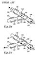
- This kind of valve is shown in more detail with the valve vane in the first position in figure 2a and in the second position in figure 2b .
- Such a valve is previously known through US 5.279.854 , which displays an apparatus for applying superabsorbent particles on pre-determined areas of a fibrous material. Air-entrained absorbent particles are directed through a valve which alternately is directing the particles to a first and a second nozzle supplying the particles to the absorbent structure, which allows the particles to de deposited on the absorbent structure on pre-determined areas.
- US 5,102,585 relates to a method for forming a zoned distribution of particulate material within a fibrous web by providing a gas entrained supply of the particulate material and centrifugally directing the particulate material into an accumulation region.
- the particulate material is transferred in selected quantities from the accumulation region into a delivery gas stream through a delivery conduit and into a web forming chamber.
- a foraminous forming layer is disposed within the forming chamber for receiving fibrous material and the particulate material to produce a fibrous web which includes zoned regions having selected, different amounts of the particulate material therein.
- An object of the present invention is to provide an improved apparatus for giving a particle flow a distinct trailing edge, which particle flow comprises particles for application within a pre-determined limited area of an absorbent structure according to the preamble of claim 1 or 2
- a further object of the present invention is to provide an improved method for giving a particle flow a distinct trailing edge, which particle flow comprises particles for application within a pre-determined limited area of an absorbent structure according to the preamble of claim 11.
- a gas flow may be maintained in the outlet conduit when the valve is in its second, i.e. its closed position.
- the problem of the "tailing effect” described above in connection with previously known valves is avoided, where not only the particle flow in the outlet conduit but also the airflow transporting the particles is throttled when the valve is in its second position.
- the last particles will be deposited with a lower outlet speed than the particles where the air pressure is kept on a maximum, leading to a "tail" formed by the last particles.
- a "tailing effect” may be avoided and the application of particles may, thus, be controlled in a more pre-determined manner.
- FIG. 1 A prior art system for applying particles to an absorbent structure is shown in figure 1 , where a rotating mat-forming wheel 180 is used to form fibrous material into an absorbent structure for use in an absorbent article, such as sanitary napkins, panty liners, diapers, bed protections and incontinence guards.
- a hood 190 is arranged above the mat-forming wheel 180 to which fibrous material for the forming of the actual absorbent structure is carried.
- the mat-forming wheel comprises in a conventional manner moulds into which fibrous material is sucked by means of an under pressure for the forming of discrete absorption bodies.
- a nozzle 120 arranged, which dispenses superabsorbent polymer particles within a pre-determined area during forming of the absorbent body.
- the nozzle 120 is further connected to an outlet conduit 140 wherein airborne particles are transported.
- the actual apparatus for supplying the particles comprises a particle container (not shown) from which particles are transferred to a feeder 110, e.g. by means of a vacuum pump (not shown).
- the feeder 110 may, for example, be of a vibrator feeder or screw feeder type.
- the feeder 110 is arranged to feed an even pre-determined amount of particles per unit of time.
- From the feeder the particles are transported by means of gas, preferably air, through a pipe system to the nozzle 120.
- the transporting gas flow (airflow) is created, e.g. by means of pneumatically driven ejectors, pumps including ejectors or by using a fan (not shown in figure 1 ).
- a diverting valve 100 is arranged between the feeder 110 and the nozzle 120 .
- the diverting valve 100 is in a first position directing airborne particles from the feeder 110 to the nozzle 120, and in a second position the diverting valve is directing the airborne particles from the feeder 110 to a collecting container 170.
- the particles returning to the collecting container 170 are then recycled.
- the pipe system comprises a particle transport conduit 130 connected to the feeder 110 and the valve 100, an outlet conduit 140 arranged between the valve 100 and the nozzle 120 and, a return conduit 150 arranged between the valve 100 and the collecting container 170.
- FIGS 2a and 2b show in cross-section the prior art valve 100 in a first and a second position respectively.
- the valve 100 comprises a particle inlet 135 connected to the particle transport conduit 130, an application outlet 145 connected to the outlet conduit 140 and, a residue outlet 155 connected to the return conduit 150.
- a valve vane 115 Arranged in the valve 100 is a valve vane 115 which is arranged to alternately direct the airborne particle flow to the application outlet 145 and the residue outlet 155.
- the valve vane is e.g. controlled by means of a pneumatic cylinder or a servo-motor.
- FIGS 2a and 2b are also shown three ejectors 105 arranged at the inlet 135 and at the outlets 145 and 155 respectively.
- the airborne particle flow is controlled by alternately setting the valve in a first and a second position.
- the SAP layer gets a badly defined trailing edge having a long drawn-out tail when such a valve is used.
- the inventors of the present invention have realized that the reason for this is that when the valve is set in its second position not only the particle flow in the outlet conduit is throttled but also the airflow transporting the particles. This leads to that the particles which are in the outlet conduit when the valve is set in the second position get a lower speed than the other particles where the air pressure is on a maximum.
- the effect of a throttled airflow is that the last particles supplied to the absorbent structure are forming a tail, a so called "tailing effect".
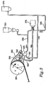
- FIG. 3 One example of an inventive apparatus for applying particles, especially SAP particles, on a fibrous material is shown in figure 3 , where a rotating mat-forming wheel 380 is used to form fibrous material into an absorbent structure for use in an absorbent article, such as sanitary napkins, panty liners, incontinence guards, diapers and bed protections.
- a hood 390 is arranged above the mat-forming wheel 380 to which fibrous material for the forming of the actual absorbent structure is carried.
- the mat-forming wheel comprises in a conventional manner moulds into which fibrous material is sucked by means of an under pressure for the forming of discrete absorption bodies.
- a nozzle 320 arranged, which dispenses superabsorbent polymer particles within a pre-determined area during forming of the absorption body.
- the nozzle 320 is further connected to an outlet conduit 340, also called particle application conduit, wherein airborne particles are transported.
- the nozzle 320 may be placed on different locations in the hood 390, depending on the desired location of the pre-determined area for the particles.
- the actual apparatus for supplying the particles comprises a particle container (not shown) from which particles are transferred to a feeder 310, e.g. by means of a vacuum pump (not shown).
- the feeder 310 may, for example, be of a vibrator feeder or screw feeder type.
- the feeder 310 is arranged to feed an even pre-determined amount of particles per unit of time.
- From the feeder the particles are transported by means of gas, preferably air, through a pipe system to the nozzle 320.
- the transporting gas flow (airflow) is created, e.g. by means of pneumatically driven ejectors, pumps including ejectors or by using a fan.
- a fan 375 is used for creating the airflow.
- a diverting valve 300 is arranged, which in this exemplifying figure correspond to the valve shown in figures 5a and 5b .
- the diverting valve 300 is in a first position directing airborne particles from the feeder 310 to the nozzle 320, and in a second position the diverting valve 300 is directing the airborne particles from the feeder 310 to a collecting container 370. The particles returning to the collecting container 370 are then recycled.
- the pipe system comprises a particle inlet conduit 330 connected to the feeder 310 and the valve 300, an application outlet conduit 340 arranged between the valve 300 and the nozzle 320 and, a residue outlet conduit 350, herein a return conduit, arranged between the valve 300 and the collecting container 370.
- the pipe system further comprises a particle-free inlet conduit 360 connected to the valve 300, which transports clean carrier gas without particles and which is arranged between the valve 300 and the fan 375.
- a second gas conduit 385 arranged at the fan 375 and connected to the residue outlet conduit 350 in order to assist the returning particle flow to the collecting container 370.
- the carrier gas may suitably be air.
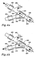
- a valve 400 comprises a valve vane 415, a particle inlet 435, an application outlet 445 and a residue outlet 455.
- the valve vane is pivotally arranged between the application outlet 445 and the residue outlet 455 and is e.g. controlled by means of a pneumatic cylinder or a servo-motor (not shown in the figures).
- the particle inlet 435 is communicating with the feeder (shown in figure 3 ) via the particle inlet conduit 430 in which the airborne particles are transported from the feeder.
- the application outlet 445 is communicating with the nozzle (shown in figure 3 ) via the connected particle application conduit 440.
- the residue outlet 455 is communicating with the particle collector (shown in figure 3 ) via the residue outlet conduit 450, which herein is a return conduit in which airborne particles are returned.
- the particle-free inlet conduit 460 is connected to the particle application conduit 440 to which it leads. In the particle-free inlet conduit 460 clean air is transported, i.e. without particles, and thereby is guaranteed that the airflow in the particle application conduit 440 not is throttled but is maintained when the valve vane switches position.
- the airflow is created by means of three pneumatically driven ejectors 405 arranged at the particle inlet 435 and at outlets 445 and 455 respectively.
- Figure 4a shows the valve 400 in its first position when the valve vane 415 is closing the residue outlet 455.
- the airborne particles are, thus, directed from the particle inlet 435 through the valve to the application outlet 445 and thereafter through the particle application conduit 440 where they are mixed with the extra supplied air from the particle-free inlet conduit 460 and further to the nozzle for dispensing on the fibrous material.
- Figure 4b shows the valve 400 in its second position when the valve vane 415 is closing the application outlet 445.
- the valve 400 When the valve 400 is in the second position the airborne particles are directed from the particle inlet 435 through the valve 400 to the residue outlet 455 and thereafter to the return conduit 450 for further transport to the collecting container.
- clean carrier gas is guided from the particle-free inlet conduit 460 through the particle application conduit 440 making sure that possibly left particles are dispensed in an even pace.
- a valve 500 comprises a valve vane 515, a particle inlet 535, an application outlet 545 and a residue outlet 555.
- the valve vane is pivotally arranged on a shaft and is e.g. controlled by means of a pneumatic cylinder or a servo-motor (not shown in the figures).
- the particle inlet 535 is communicating with the feeder (shown in figure 3 ) via the particle inlet conduit 530 in which the airborne particles are transported from the feeder.
- the application outlet 545 is communicating with the nozzle (shown in figure 3 ) via the connected particle application conduit 540.
- the residue inlet 555 is communicating with the particle collector (shown in figure 3 ) via the residue outlet conduit 550, in which airborne particles are returned.
- the valve 500 further comprises a particle-free inlet 565 connected to a particle-free inlet conduit 560 in which clean air, i.e. without particles, is transported.
- the particle-free inlet 565 is herein arranged between the application outlet 545 and the residue outlet 555 downstream the valve vane 515.
- Figure 5a shows the valve 500 in its first position when the valve vane 515 is set such, that the airborne particles are directed through the valve 500 from the particle inlet 535 to the application outlet 545 and further on to the nozzle (not shown in figure 5a ) to be mixed with the fibrous material in the absorption body.
- Particle-free air is at the same time directed through the valve from the particle-free inlet 565 to the residue outlet 555 and further on to the residue outlet conduit 550.
- Figure 5b shows the valve 500 in its second position when the valve vane is set such that the airborne particles are directed through the valve 500 from the particle inlet 535 to the residue outlet 555 and further on to the collecting container (not shown in figure 5b ).
- Clean air is at the same time directed in through the valve 500 from the particle-free inlet 565 to the application outlet 545 and thus guarantees that the airflow in the application outlet conduit 540 not is throttled but is maintained when the valve is in its second position.
- the valve according to the second embodiment of the invention gives a stable airflow towards the mat-forming wheel without pulsations irrespective of if the valve is in the first or second position.
- the valve 600 comprises a chamber 680, whereby the chamber 680 comprises a particle inlet 635, a particle-free inlet 665, an application outlet 645 and a residue outlet 655.
- the particle inlet 635 is connected to a tubular member 675 via a flexible bellows 678.
- the tubular member 675 is in its first end 677 suspended around an axis 625, whereby the tubular member 675 is pivotal around the axis 625.
- the tubular member 675 When the tubular member 675 is pivoted, the second end 679 of the tubular member 675 is moved from the application outlet 645 to the residue outlet 655 (or the other way around), whereby the tubular member 675 forms the valve vane 615. Pivoting of the tubular member 675 is e.g. controlled by means of a pneumatic cylinder or a servo-motor, or the like (not shown in the figures).
- the length of the tubular member 675 is adapted such that the second end 679 of the tubular member 675 connects to the application outlet 645 when the tubular member 675 is in its first outer position (shown in figure 6a ) and connects to the residue outlet 655 when the tubular member 675 is in its second outer position (shown in figure 6b ).
- the application outlet 645 is communicating with the nozzle (shown in figure 3 ) via the connected particle application conduit 640.
- the residue outlet 655 is communicating with the particle collector (shown in figure 3 ) via the residue outlet conduit 650, in which airborne particles are returned.
- the valve 600 further comprises a particle-free inlet 665 connected to a particle-free inlet conduit 660 in which clean air, i.e. without particles, is transported.
- Figure 6a shows the valve 600 in its first position when the valve vane 615 (tubular member 675) is set such, that the airborne particles are directed through the valve 600 from the particle inlet 635 to the application outlet 645 and further on to the nozzle (not shown in figure 6a ).
- the particle-free air is at the same time directed into the valve 600 from the particle-free inlet 665 through the chamber 680 and out through the residue outlet 655.
- Figure 6b shows the valve 600 in its second position when the valve vane 615 (tubular member 675) is set such, that the airborne particles are directed through the valve 600 from the particle inlet 635 to the residue outlet 655 and further on to the collecting container.
- the particle-free air is at the same time directed in through the valve 600 from the particle-free inlet 665 through the chamber 680 to the application outlet 645 and thus guarantees that the airflow in the application outlet conduit 640 not is throttled but is maintained.
- An inventive method for applying particles within a pre-determined limited area of an absorbent structure comprises the steps of: supplying particles by means of a gas flow from a particle container; dispensing the particles on the pre-determined limited area of the absorbent structure by means of a nozzle; providing a valve between the nozzle and the particle container; directing the gas flow comprising particles through the valve from a particle inlet to an application outlet connected to a particle application conduit when the valve is in a first position; directing the gas flow comprising particles through the valve from the inlet to a residue outlet connected to a residue outlet conduit when the valve is in a second position; and maintaining a gas flow through the application outlet conduit when the valve is in the second position.
- valve vane may vary, just as the geometrical arrangement of inlet and outlet conduits.
- the application of particles may be done in one or several areas in or on the absorbent structure.
- inventive apparatus and the method have in the shown embodiments been used with a mat-forming wheel for forming of the absorbent structure.
- the apparatus and method may, however, be used also with other manufacturing methods of the absorbent structure, such as application of particles on a web material, e.g. a fibrous material.
Landscapes
- Health & Medical Sciences (AREA)
- Engineering & Computer Science (AREA)
- Vascular Medicine (AREA)
- Epidemiology (AREA)
- Biomedical Technology (AREA)
- Heart & Thoracic Surgery (AREA)
- Manufacturing & Machinery (AREA)
- Life Sciences & Earth Sciences (AREA)
- Animal Behavior & Ethology (AREA)
- General Health & Medical Sciences (AREA)
- Public Health (AREA)
- Veterinary Medicine (AREA)
- Absorbent Articles And Supports Therefor (AREA)
- Application Of Or Painting With Fluid Materials (AREA)
- Coating Apparatus (AREA)
Description
- The present invention relates to an apparatus and a method for applying particles in an absorbent structure and relates, specifically, to an apparatus allowing for applying particles within a pre-determined limited area of an absorbent structure as well as a method for such application.
- There is today a variety of absorbent articles, such as sanitary napkins, panty liners, diapers, bed protections and incontinence guards, having different shapes and dimensions on the market. Such an absorbent article usually comprises an absorbent structure formed to absorb body fluids under a short period of time and to distribute and store body fluids. This means that the absorbent structure usually comprises several different layers having different characteristics in relation to each other. The absorbent structure often comprises at least a liquid acquisition layer, a liquid storage layer and a liquid distribution layer.
- As a liquid acquisition layer is usually used a porous material having a high momentaneous liquid receiving capacity. Examples of such materials are cellulosic fluff pulp of thermomechanic or chemothermomechanic (CTMP) type, chemically stiffened cellulosic fibres, synthetic fiber structures of different types and porous foam materials etc.
- As a storage layer is usually cellulosic fluff pulp mixed with so called superabsorbents used, or superabsorbent polymer particles (SAP), i.e. crosslinked polymers having the ability to absorb several times their own weight (10 times or more).
- As distribution layer may cellulosic fluff pulp, tissue layer, foam, synthetic fibers and the like having high liquid distribution capacity be used. It is also possible to combine two or more of the functions acquisition, storage and distribution in one and the same layer. Since superabsorbent particles are more expensive than natural or synthetic fibermaterials, it is advantageous to reduce the amount of superabsorbent particles in the absorbent structure. Rather than reduce the amount of such particles throughout the entire structure, it is desirable to distribute the particles in the structure in a pre-determined manner such that the particles are where it is most efficient to receive and store body fluids.
- In order to be able to apply the superabsorbent particles on pre-determined areas of the absorbent structure, commonly airborne superabsorbent particles are directed through a valve, where the supplying of particles to the absorbent structure is controlled by means of a valve vane. Such an apparatus for applying particles on an absorbent structure is shown in
figure 1 . When a valve vane arranged in the valve is in a first position, the airborne particles are directed through the valve to a nozzle supplying the particles to the absorbent structure. When the valve vane is in a second position, the airborne particles are directed through the valve to a collecting container for recycling of the particles. This kind of valve is shown in more detail with the valve vane in the first position infigure 2a and in the second position infigure 2b . - Such a valve is previously known through
US 5.279.854 , which displays an apparatus for applying superabsorbent particles on pre-determined areas of a fibrous material. Air-entrained absorbent particles are directed through a valve which alternately is directing the particles to a first and a second nozzle supplying the particles to the absorbent structure, which allows the particles to de deposited on the absorbent structure on pre-determined areas. - However, it has turned out that when a valve of the kind described above is in its second position, the particles that are in the outlet conduit when the valve is switched to the second position will be dispensed on the fibrous material forming a "tail" to the pre-determined area, a so called tailing effect. It is desirable to get rid of this "tail" and obtain a distinct ending of the particle provided areas of the absorbent structure, in order to reduce the consumption of particles and at the same time make an aesthetically attractive effect. Further, particles in the "tail" may even end up outside the absorbent structure, e.g. directly between a surface material and a back layer. Since superabsorbent particles often form sharp granules, it may in this case cause discomfort at use of the article, which is yet another reason for desiring to avoid the forming of a tail of particles.
-
US 5,102,585 relates to a method for forming a zoned distribution of particulate material within a fibrous web by providing a gas entrained supply of the particulate material and centrifugally directing the particulate material into an accumulation region. The particulate material is transferred in selected quantities from the accumulation region into a delivery gas stream through a delivery conduit and into a web forming chamber. A foraminous forming layer is disposed within the forming chamber for receiving fibrous material and the particulate material to produce a fibrous web which includes zoned regions having selected, different amounts of the particulate material therein. - An object of the present invention is to provide an improved apparatus for giving a particle flow a distinct trailing edge, which particle flow comprises particles for application within a pre-determined limited area of an absorbent structure according to the preamble of claim 1 or 2
- This object has been achieved through an apparatus according to the characterizing portion of claim 1 or 2
- A further object of the present invention is to provide an improved method for giving a particle flow a distinct trailing edge, which particle flow comprises particles for application within a pre-determined limited area of an absorbent structure according to the preamble of claim 11.
- This further object has been achieved through a method according to the characterizing portion of claim 11.
- Preferred embodiments are disclosed in the dependent claims.
- According to the invention a gas flow may be maintained in the outlet conduit when the valve is in its second, i.e. its closed position. This leads to that the particles in the outlet conduit when the valve switches to the second position get the same outlet speed as the other particles had. In this manner the problem of the "tailing effect" described above in connection with previously known valves is avoided, where not only the particle flow in the outlet conduit but also the airflow transporting the particles is throttled when the valve is in its second position. In the prior art valves, the last particles will be deposited with a lower outlet speed than the particles where the air pressure is kept on a maximum, leading to a "tail" formed by the last particles.
- According to the invention a "tailing effect" may be avoided and the application of particles may, thus, be controlled in a more pre-determined manner.
- Still other objects and features of the present invention will become apparent from the following detailed description considered in conjunction with the accompanying drawings. It is to be understood, however, that the drawings are designed solely for purposes of illustration and not as a definition of the limits of the invention, for which reference should be made to the appended claims. It should be further understood that the drawings are not necessarily drawn to scale and that, unless otherwise indicated, they are merely intended to conceptually illustrate the structures and procedures described herein.
- In the drawings like reference characters denote similar elements throughout the several views and:
-
Figure 1 shows a system comprising a prior art valve for applying particles on a fibrous material; -
Figures 2a and 2b are a cross-sectional view of a prior art valve in a first and a second position respectively; -
Figure 3 shows a system comprising an inventive apparatus for applying particles on a fibrous material; -
Figures 4a and 4b are a cross-sectional illustrative view of a valve which is not part of the invention in a first and a second position respectively; -
Figures 5a and 5b are a cross-sectional view of a first embodiment of an inventive valve in a first and a second position respectively; -
Figures 6a and 6b are a cross-sectional view of a second embodiment of an inventive valve in a first and a second position respectively. - A prior art system for applying particles to an absorbent structure is shown in
figure 1 , where a rotating mat-formingwheel 180 is used to form fibrous material into an absorbent structure for use in an absorbent article, such as sanitary napkins, panty liners, diapers, bed protections and incontinence guards. Ahood 190 is arranged above the mat-formingwheel 180 to which fibrous material for the forming of the actual absorbent structure is carried. The mat-forming wheel comprises in a conventional manner moulds into which fibrous material is sucked by means of an under pressure for the forming of discrete absorption bodies. In thehood 190 is further anozzle 120 arranged, which dispenses superabsorbent polymer particles within a pre-determined area during forming of the absorbent body. Thenozzle 120 is further connected to anoutlet conduit 140 wherein airborne particles are transported. - The actual apparatus for supplying the particles comprises a particle container (not shown) from which particles are transferred to a
feeder 110, e.g. by means of a vacuum pump (not shown). Thefeeder 110 may, for example, be of a vibrator feeder or screw feeder type. Thefeeder 110 is arranged to feed an even pre-determined amount of particles per unit of time. From the feeder the particles are transported by means of gas, preferably air, through a pipe system to thenozzle 120. The transporting gas flow (airflow) is created, e.g. by means of pneumatically driven ejectors, pumps including ejectors or by using a fan (not shown infigure 1 ). Between thefeeder 110 and the nozzle 120 a divertingvalve 100 is arranged. The divertingvalve 100 is in a first position directing airborne particles from thefeeder 110 to thenozzle 120, and in a second position the diverting valve is directing the airborne particles from thefeeder 110 to acollecting container 170. The particles returning to the collectingcontainer 170 are then recycled. The pipe system comprises aparticle transport conduit 130 connected to thefeeder 110 and thevalve 100, anoutlet conduit 140 arranged between thevalve 100 and thenozzle 120 and, areturn conduit 150 arranged between thevalve 100 and thecollecting container 170. -
Figures 2a and 2b show in cross-section theprior art valve 100 in a first and a second position respectively. Thevalve 100 comprises aparticle inlet 135 connected to theparticle transport conduit 130, anapplication outlet 145 connected to theoutlet conduit 140 and, aresidue outlet 155 connected to thereturn conduit 150. Arranged in thevalve 100 is avalve vane 115 which is arranged to alternately direct the airborne particle flow to theapplication outlet 145 and theresidue outlet 155. The valve vane is e.g. controlled by means of a pneumatic cylinder or a servo-motor. Infigures 2a and 2b are also shown threeejectors 105 arranged at theinlet 135 and at theoutlets - In order to apply the particles on a pre-determined position of the fibrous material, i.e applying an intermittent SAP layer on an absorbent structure, so called zoning, the airborne particle flow is controlled by alternately setting the valve in a first and a second position. However, it has turned out that the SAP layer gets a badly defined trailing edge having a long drawn-out tail when such a valve is used. The inventors of the present invention have realized that the reason for this is that when the valve is set in its second position not only the particle flow in the outlet conduit is throttled but also the airflow transporting the particles. This leads to that the particles which are in the outlet conduit when the valve is set in the second position get a lower speed than the other particles where the air pressure is on a maximum. The effect of a throttled airflow is that the last particles supplied to the absorbent structure are forming a tail, a so called "tailing effect".
- One example of an inventive apparatus for applying particles, especially SAP particles, on a fibrous material is shown in
figure 3 , where a rotating mat-formingwheel 380 is used to form fibrous material into an absorbent structure for use in an absorbent article, such as sanitary napkins, panty liners, incontinence guards, diapers and bed protections. Ahood 390 is arranged above the mat-formingwheel 380 to which fibrous material for the forming of the actual absorbent structure is carried. The mat-forming wheel comprises in a conventional manner moulds into which fibrous material is sucked by means of an under pressure for the forming of discrete absorption bodies. In thehood 390 is further anozzle 320 arranged, which dispenses superabsorbent polymer particles within a pre-determined area during forming of the absorption body. Thenozzle 320 is further connected to anoutlet conduit 340, also called particle application conduit, wherein airborne particles are transported. Thenozzle 320 may be placed on different locations in thehood 390, depending on the desired location of the pre-determined area for the particles. - The actual apparatus for supplying the particles comprises a particle container (not shown) from which particles are transferred to a
feeder 310, e.g. by means of a vacuum pump (not shown). Thefeeder 310 may, for example, be of a vibrator feeder or screw feeder type. Thefeeder 310 is arranged to feed an even pre-determined amount of particles per unit of time. From the feeder the particles are transported by means of gas, preferably air, through a pipe system to thenozzle 320. The transporting gas flow (airflow) is created, e.g. by means of pneumatically driven ejectors, pumps including ejectors or by using a fan. In the example shown infigure 3 , afan 375 is used for creating the airflow. Between thefeeder 310 and the nozzle 320 a divertingvalve 300 is arranged, which in this exemplifying figure correspond to the valve shown infigures 5a and 5b . The divertingvalve 300 is in a first position directing airborne particles from thefeeder 310 to thenozzle 320, and in a second position the divertingvalve 300 is directing the airborne particles from thefeeder 310 to a collectingcontainer 370. The particles returning to the collectingcontainer 370 are then recycled. - The pipe system comprises a
particle inlet conduit 330 connected to thefeeder 310 and thevalve 300, anapplication outlet conduit 340 arranged between thevalve 300 and thenozzle 320 and, aresidue outlet conduit 350, herein a return conduit, arranged between thevalve 300 and the collectingcontainer 370. The pipe system further comprises a particle-free inlet conduit 360 connected to thevalve 300, which transports clean carrier gas without particles and which is arranged between thevalve 300 and thefan 375. In the figure is also shown asecond gas conduit 385 arranged at thefan 375 and connected to theresidue outlet conduit 350 in order to assist the returning particle flow to the collectingcontainer 370. The carrier gas may suitably be air. - An illustrative embodiment of a valve which is not part of the present invention is shown in the
figures 4a and 4b , wherein avalve 400 comprises avalve vane 415, aparticle inlet 435, anapplication outlet 445 and aresidue outlet 455. The valve vane is pivotally arranged between theapplication outlet 445 and theresidue outlet 455 and is e.g. controlled by means of a pneumatic cylinder or a servo-motor (not shown in the figures). Theparticle inlet 435 is communicating with the feeder (shown infigure 3 ) via theparticle inlet conduit 430 in which the airborne particles are transported from the feeder. Theapplication outlet 445 is communicating with the nozzle (shown infigure 3 ) via the connectedparticle application conduit 440. Theresidue outlet 455 is communicating with the particle collector (shown infigure 3 ) via theresidue outlet conduit 450, which herein is a return conduit in which airborne particles are returned. The particle-free inlet conduit 460 is connected to theparticle application conduit 440 to which it leads. In the particle-free inlet conduit 460 clean air is transported, i.e. without particles, and thereby is guaranteed that the airflow in theparticle application conduit 440 not is throttled but is maintained when the valve vane switches position. In the embodiment shown infigure 4a and 4b the airflow is created by means of three pneumatically drivenejectors 405 arranged at theparticle inlet 435 and atoutlets -
Figure 4a shows thevalve 400 in its first position when thevalve vane 415 is closing theresidue outlet 455. When thevalve 400 is in its first position, the airborne particles are, thus, directed from theparticle inlet 435 through the valve to theapplication outlet 445 and thereafter through theparticle application conduit 440 where they are mixed with the extra supplied air from the particle-free inlet conduit 460 and further to the nozzle for dispensing on the fibrous material. -
Figure 4b shows thevalve 400 in its second position when thevalve vane 415 is closing theapplication outlet 445. When thevalve 400 is in the second position the airborne particles are directed from theparticle inlet 435 through thevalve 400 to theresidue outlet 455 and thereafter to thereturn conduit 450 for further transport to the collecting container. At the same time, clean carrier gas is guided from the particle-free inlet conduit 460 through theparticle application conduit 440 making sure that possibly left particles are dispensed in an even pace. - A first preferred embodiment of the present invention is shown in
figures 5a and 5b , wherein avalve 500 comprises avalve vane 515, aparticle inlet 535, anapplication outlet 545 and aresidue outlet 555. The valve vane is pivotally arranged on a shaft and is e.g. controlled by means of a pneumatic cylinder or a servo-motor (not shown in the figures). Theparticle inlet 535 is communicating with the feeder (shown infigure 3 ) via theparticle inlet conduit 530 in which the airborne particles are transported from the feeder. Theapplication outlet 545 is communicating with the nozzle (shown infigure 3 ) via the connectedparticle application conduit 540. Theresidue inlet 555 is communicating with the particle collector (shown infigure 3 ) via theresidue outlet conduit 550, in which airborne particles are returned. Thevalve 500 further comprises a particle-free inlet 565 connected to a particle-free inlet conduit 560 in which clean air, i.e. without particles, is transported. The particle-free inlet 565 is herein arranged between theapplication outlet 545 and theresidue outlet 555 downstream thevalve vane 515. -
Figure 5a shows thevalve 500 in its first position when thevalve vane 515 is set such, that the airborne particles are directed through thevalve 500 from theparticle inlet 535 to theapplication outlet 545 and further on to the nozzle (not shown infigure 5a ) to be mixed with the fibrous material in the absorption body. Particle-free air is at the same time directed through the valve from the particle-free inlet 565 to theresidue outlet 555 and further on to theresidue outlet conduit 550. -
Figure 5b shows thevalve 500 in its second position when the valve vane is set such that the airborne particles are directed through thevalve 500 from theparticle inlet 535 to theresidue outlet 555 and further on to the collecting container (not shown infigure 5b ). - Clean air is at the same time directed in through the
valve 500 from the particle-free inlet 565 to theapplication outlet 545 and thus guarantees that the airflow in theapplication outlet conduit 540 not is throttled but is maintained when the valve is in its second position. - The valve according to the second embodiment of the invention gives a stable airflow towards the mat-forming wheel without pulsations irrespective of if the valve is in the first or second position.
- According to a second embodiment shown in
figures 6a and 6b , thevalve 600 comprises achamber 680, whereby thechamber 680 comprises aparticle inlet 635, a particle-free inlet 665, anapplication outlet 645 and aresidue outlet 655. - Inside the
chamber 680, theparticle inlet 635 is connected to atubular member 675 via a flexible bellows 678. Thetubular member 675 is in itsfirst end 677 suspended around anaxis 625, whereby thetubular member 675 is pivotal around theaxis 625. - When the
tubular member 675 is pivoted, thesecond end 679 of thetubular member 675 is moved from theapplication outlet 645 to the residue outlet 655 (or the other way around), whereby thetubular member 675 forms thevalve vane 615. Pivoting of thetubular member 675 is e.g. controlled by means of a pneumatic cylinder or a servo-motor, or the like (not shown in the figures). - The length of the
tubular member 675 is adapted such that thesecond end 679 of thetubular member 675 connects to theapplication outlet 645 when thetubular member 675 is in its first outer position (shown infigure 6a ) and connects to theresidue outlet 655 when thetubular member 675 is in its second outer position (shown infigure 6b ). - The
application outlet 645 is communicating with the nozzle (shown infigure 3 ) via the connectedparticle application conduit 640. Theresidue outlet 655 is communicating with the particle collector (shown infigure 3 ) via theresidue outlet conduit 650, in which airborne particles are returned. Thevalve 600 further comprises a particle-free inlet 665 connected to a particle-free inlet conduit 660 in which clean air, i.e. without particles, is transported. -
Figure 6a shows thevalve 600 in its first position when the valve vane 615 (tubular member 675) is set such, that the airborne particles are directed through thevalve 600 from theparticle inlet 635 to theapplication outlet 645 and further on to the nozzle (not shown infigure 6a ). The particle-free air is at the same time directed into thevalve 600 from the particle-free inlet 665 through thechamber 680 and out through theresidue outlet 655. -
Figure 6b shows thevalve 600 in its second position when the valve vane 615 (tubular member 675) is set such, that the airborne particles are directed through thevalve 600 from theparticle inlet 635 to theresidue outlet 655 and further on to the collecting container. The particle-free air is at the same time directed in through thevalve 600 from the particle-free inlet 665 through thechamber 680 to theapplication outlet 645 and thus guarantees that the airflow in theapplication outlet conduit 640 not is throttled but is maintained. - The shown embodiment in
figures 6a and 6b also guarantees an even airflow towards the mat-forming wheel. - An inventive method for applying particles within a pre-determined limited area of an absorbent structure comprises the steps of: supplying particles by means of a gas flow from a particle container; dispensing the particles on the pre-determined limited area of the absorbent structure by means of a nozzle; providing a valve between the nozzle and the particle container; directing the gas flow comprising particles through the valve from a particle inlet to an application outlet connected to a particle application conduit when the valve is in a first position; directing the gas flow comprising particles through the valve from the inlet to a residue outlet connected to a residue outlet conduit when the valve is in a second position; and maintaining a gas flow through the application outlet conduit when the valve is in the second position.
- Variations of the method are clear from the above described embodiments of the inventive apparatus.
- It is realized that several variations are possible within the scope of the invention. E.g. the shape of the valve vane may vary, just as the geometrical arrangement of inlet and outlet conduits. The application of particles may be done in one or several areas in or on the absorbent structure. The inventive apparatus and the method have in the shown embodiments been used with a mat-forming wheel for forming of the absorbent structure. The apparatus and method may, however, be used also with other manufacturing methods of the absorbent structure, such as application of particles on a web material, e.g. a fibrous material.
Claims (12)
- An apparatus for applying particles within a pre-determined limited area of an absorbent structure, which apparatus comprises:- a nozzle (320) arranged to dispense the particles on the pre-determined limited area of the absorbent structure;- means (310, 330, 340) for supplying particles by means of a gas flow from a particle container to the nozzle (320);- a valve (300, 500) arranged between the nozzle (320) and the particle container;- one in the valve arranged valve vane (515) arranged to direct the gas flow comprising particles through the valve (300, 500) from a particle inlet (535) to an application outlet (545) when the valve is in a first position and to direct the gas flow comprising particles through the valve (300, 500) from the particle inlet (535) to a residue outlet (555) when the valve is in a second position;
wherein the apparatus further comprises means (360, 560,) for maintaining a gas flow in the application outlet (545) when the valve (300, 500) is in the second position.
said means for maintaining a gas flow comprises a particle-free inlet (565) in the valve (500), which particle-free inlet (565) is arranged to supply a particle-free gas flow;
characterised in that
the particle-free inlet (565) is arranged between the application outlet (545) and the residue outlet (555) downstream the valve vane (515), whereby the valve vane (515) is arranged to direct the particle-free gas flow through the valve (500) from the particle-free inlet (565) to the application outlet (545) when the valve (500) is in the second position and to direct the particle-free gas flow from the particle-free inlet (565) to the residue outlet (555) when the valve (500) is in the first position. - An apparatus for applying particles within a pre-determined limited area of an absorbent structure, which apparatus comprises:- a nozzle (320) arranged to dispense the particles on the pre-determined limited area of the absorbent structure;- means (310, 330, 340) for supplying particles by means of a gas flow from a particle container to the nozzle (320);- a valve (300, 600) arranged between the nozzle (320) and the particle container;- one in the valve arranged valve vane (615) arranged to direct the gas flow comprising particles through the valve (300, 600) from a particle inlet (635) to an application outlet (645) when the valve is in a first position and to direct the gas flow comprising particles through the valve (300, 600) from the particle inlet (635) to a residue outlet (655) when the valve is in a second position;
wherein the apparatus further comprises means (360, 660) for maintaining a gas flow in the application outlet (645) when the valve (300, 600) is in the second position
said means for maintaining a gas flow comprises a particle-free inlet (665) in the valve (600), which particle-free inlet (665) is arranged to supply a particle-free gas flow;
characterised in that
the valve vane (615) is formed as a tube (675) flexibly connected to the particle inlet (635) and arranged to direct the particle flow from the particle inlet (635) to the application outlet (645) when the valve is in the first position, and from the particle inlet (635) to the residue outlet (655) when the valve is in the second position. - An apparatus according to claim 1 or 2, whereby the application outlet (545, 645) is connected to a particle application conduit (340, 540, 640) and the residue outlet (555, 655) is connected to a residue outlet conduit (350, 550, 650). whereby the means (360, 560, 660) for maintaining a gas flow in the application outlet is maintaining a gas flow in the application outlet conduit (340, 540, 640) when the valve is in the second position.
- An apparatus according to any of claims 1-3, whereby a particle-free inlet conduit (560, 660) is connected to the particle-free inlet (565, 665) in the valve (500, 600) for supplying a particle-free gas flow.
- An apparatus according to claim 2, whereby the particle-free gas flow from the particle-free inlet (665) is guided to the residue outlet (655) when the valve is in the first position, and to the application outlet (645) when the valve (600) is in the second position.
- An apparatus according to any of the preceding claims, whereby said residue outlet conduit (350, 550,650) is arranged to transport the gas flow comprising particles to a collecting arrangement (370) for recycling of the particles.
- An apparatus according to any of the preceding claims, whereby the apparatus further comprises at least one pneumatically driven ejector (405) arranged to create said gas flow.
- An apparatus according to any of the preceding claims, whereby the apparatus further comprises at least one fan (375) arranged to create said gas flow.
- An apparatus according to any of the preceding claims, whereby said gas is air.
- An apparatus according to any of the preceding claims, whereby said particles are superabsorbent polymer particles (SAP).
- A method for applying particles within a pre-determined limited area of an absorbent structure comprising the steps of:- supplying particles by means of a gas flow from a particle container;- dispensing the particles on the pre-determined limited area of the absorbent structure by means of a nozzle;- providing a valve between the nozzle and the particle container;- directing the gas flow comprising particles through the valve from a particle inlet to an application outlet when the valve is in a first position;- directing the gas flow comprising particles through the valve from the particle inlet to a residue outlet when the valve is in a second position;- maintaining a gas flow through the application outlet when the valve is in the second position;
characterised in that the method further comprises the steps of:- providing a second inlet in the valve, which particle-free inlet is arranged to supply a particle-free gas flow;- directing the particle-free gas flow from the particle-free inlet to the residue outlet when the valve is in the first position; and,- directing the particle-free gas flow through the valve from the particle-free inlet to the application outlet when the valve is in the second position. - A method according to claim 11, whereby the method further comprises the step of providing a particle application conduit connected to the application outlet, and a particle-free inlet conduit connected to the particle application conduit arranged to supply the particle-free gas flow to the particle application conduit
Applications Claiming Priority (1)
| Application Number | Priority Date | Filing Date | Title |
|---|---|---|---|
| PCT/SE2005/001946 WO2007069956A1 (en) | 2005-12-15 | 2005-12-15 | Method and device for application of particles in an absorbent structure |
Publications (3)
| Publication Number | Publication Date |
|---|---|
| EP1959891A1 EP1959891A1 (en) | 2008-08-27 |
| EP1959891A4 EP1959891A4 (en) | 2012-09-12 |
| EP1959891B1 true EP1959891B1 (en) | 2015-08-19 |
Family
ID=38163175
Family Applications (1)
| Application Number | Title | Priority Date | Filing Date |
|---|---|---|---|
| EP05821998.1A Expired - Lifetime EP1959891B1 (en) | 2005-12-15 | 2005-12-15 | Method and device for application of particles in an absorbent structure |
Country Status (5)
| Country | Link |
|---|---|
| US (1) | US7882797B2 (en) |
| EP (1) | EP1959891B1 (en) |
| JP (1) | JP4777438B2 (en) |
| CN (1) | CN101309659B (en) |
| WO (1) | WO2007069956A1 (en) |
Families Citing this family (5)
| Publication number | Priority date | Publication date | Assignee | Title |
|---|---|---|---|---|
| US9027506B2 (en) * | 2011-05-02 | 2015-05-12 | Nordson Corporation | Dense phase powder coating system for containers |
| US10226917B2 (en) * | 2015-07-27 | 2019-03-12 | Dmg Mori Seiki Usa | Powder delivery systems and methods for additive manufacturing apparatus |
| CN105662719A (en) * | 2015-12-30 | 2016-06-15 | 泉州市汉威机械制造有限公司 | Polymer intermittent applying device and applying method thereof |
| CN110179593A (en) * | 2019-07-08 | 2019-08-30 | 广东佳丝维新材料科技有限公司 | Super soft liquid absorbent wick and its preparation system and technique |
| EP4385474B1 (en) | 2022-12-13 | 2025-05-28 | Ontex BV | Apparatus for feeding and distributing superabsorbent particles onto a substrate |
Family Cites Families (11)
| Publication number | Priority date | Publication date | Assignee | Title |
|---|---|---|---|---|
| US2056266A (en) * | 1933-06-17 | 1936-10-06 | Edward G Goodell | Apparatus and process for waste liquor recovery |
| US4138161A (en) * | 1977-08-09 | 1979-02-06 | The Continental Group, Inc. | Mechanical powder flow diverting device |
| US5028224A (en) * | 1990-01-09 | 1991-07-02 | Kimberly-Clark Corporation | Apparatus for intermittently depositing particulate material in a substrate |
| US5102585A (en) * | 1990-01-09 | 1992-04-07 | Kimberly-Clark Corporation | Method for intermittently depositing particulate material in a substrate |
| US5213817A (en) * | 1991-12-12 | 1993-05-25 | Mcneil-Ppc, Inc. | Apparatus for intermittently applying particulate powder material to a fibrous substrate |
| US5248524A (en) * | 1992-01-27 | 1993-09-28 | Paragon Trade Brands | Method and apparatus for zoned application of particles in fibrous material with dual dispensing nozzles |
| US5279854A (en) | 1992-01-27 | 1994-01-18 | Paragon Trade Brands, Inc. | Method and apparatus for zoned application of particles in fibrous material |
| US5558713A (en) * | 1994-10-31 | 1996-09-24 | The Procter & Gamble Company | Method and apparatus for forming a pulsed stream of particles for application to a fibrous web |
| US5560878A (en) * | 1994-11-30 | 1996-10-01 | The Procter & Gamble Company | Method and apparatus for making stretchable absorbent articles |
| US6139912A (en) * | 1999-05-10 | 2000-10-31 | Mcneil-Ppc, Inc. | Method for intermittent application of particulate material |
| JP2004000830A (en) * | 2002-05-31 | 2004-01-08 | Zuiko Corp | Intermittent spraying equipment for powder |
-
2005
- 2005-12-15 CN CN2005800520999A patent/CN101309659B/en not_active Expired - Fee Related
- 2005-12-15 JP JP2008545527A patent/JP4777438B2/en not_active Expired - Fee Related
- 2005-12-15 WO PCT/SE2005/001946 patent/WO2007069956A1/en not_active Ceased
- 2005-12-15 EP EP05821998.1A patent/EP1959891B1/en not_active Expired - Lifetime
- 2005-12-15 US US12/085,956 patent/US7882797B2/en not_active Expired - Fee Related
Also Published As
| Publication number | Publication date |
|---|---|
| CN101309659B (en) | 2011-03-02 |
| JP4777438B2 (en) | 2011-09-21 |
| EP1959891A1 (en) | 2008-08-27 |
| US7882797B2 (en) | 2011-02-08 |
| JP2009519095A (en) | 2009-05-14 |
| US20090074960A1 (en) | 2009-03-19 |
| WO2007069956A1 (en) | 2007-06-21 |
| CN101309659A (en) | 2008-11-19 |
| EP1959891A4 (en) | 2012-09-12 |
Similar Documents
| Publication | Publication Date | Title |
|---|---|---|
| CA2203137C (en) | Method and apparatus for forming a pulsed stream of particles for application to a fibrous web | |
| US5213817A (en) | Apparatus for intermittently applying particulate powder material to a fibrous substrate | |
| US5836225A (en) | Method and apparatus for processing chopped fibers from continuous tows | |
| US8677930B2 (en) | Unit for making absorbent nappy/diaper pads | |
| JP2636915B2 (en) | Method and apparatus for depositing a water-absorbing material on a substrate | |
| KR20000053319A (en) | Absorbent products, and apparatus and method for producing the same | |
| TWI617297B (en) | Absorber manufacturing device | |
| WO2015193332A1 (en) | High speed sap particle applicator | |
| US7882797B2 (en) | Method and device for application of particles in an absorbent structure | |
| EP4378436B1 (en) | Apparatus for distributing superabsorbent particles onto a substrate | |
| EP4385474B1 (en) | Apparatus for feeding and distributing superabsorbent particles onto a substrate | |
| EP4389090A1 (en) | Apparatus for distributing absorbent fibers onto a substrate | |
| CN118317839A (en) | Apparatus for manufacturing absorbent core, particle redirector and method for redirecting particles |
Legal Events
| Date | Code | Title | Description |
|---|---|---|---|
| PUAI | Public reference made under article 153(3) epc to a published international application that has entered the european phase |
Free format text: ORIGINAL CODE: 0009012 |
|
| 17P | Request for examination filed |
Effective date: 20080326 |
|
| AK | Designated contracting states |
Kind code of ref document: A1 Designated state(s): AT BE BG CH CY CZ DE DK EE ES FI FR GB GR HU IE IS IT LI LT LU LV MC NL PL PT RO SE SI SK TR |
|
| RIN1 | Information on inventor provided before grant (corrected) |
Inventor name: FORSBRING, GOERAN |
|
| DAX | Request for extension of the european patent (deleted) | ||
| A4 | Supplementary search report drawn up and despatched |
Effective date: 20120809 |
|
| RIC1 | Information provided on ipc code assigned before grant |
Ipc: A61F 13/15 20060101AFI20120803BHEP Ipc: B05C 5/02 20060101ALI20120803BHEP Ipc: B05B 12/04 20060101ALI20120803BHEP Ipc: B05B 7/14 20060101ALI20120803BHEP |
|
| 17Q | First examination report despatched |
Effective date: 20130819 |
|
| REG | Reference to a national code |
Ref country code: DE Ref legal event code: R079 Ref document number: 602005047303 Country of ref document: DE Free format text: PREVIOUS MAIN CLASS: A61F0013150000 Ipc: B05B0015040000 |
|
| GRAP | Despatch of communication of intention to grant a patent |
Free format text: ORIGINAL CODE: EPIDOSNIGR1 |
|
| RIC1 | Information provided on ipc code assigned before grant |
Ipc: B05B 12/04 20060101ALI20150306BHEP Ipc: A61F 13/15 20060101ALI20150306BHEP Ipc: B05B 7/14 20060101ALI20150306BHEP Ipc: B05B 15/04 20060101AFI20150306BHEP |
|
| INTG | Intention to grant announced |
Effective date: 20150323 |
|
| GRAS | Grant fee paid |
Free format text: ORIGINAL CODE: EPIDOSNIGR3 |
|
| GRAA | (expected) grant |
Free format text: ORIGINAL CODE: 0009210 |
|
| AK | Designated contracting states |
Kind code of ref document: B1 Designated state(s): AT BE BG CH CY CZ DE DK EE ES FI FR GB GR HU IE IS IT LI LT LU LV MC NL PL PT RO SE SI SK TR |
|
| REG | Reference to a national code |
Ref country code: GB Ref legal event code: FG4D |
|
| REG | Reference to a national code |
Ref country code: CH Ref legal event code: EP |
|
| REG | Reference to a national code |
Ref country code: IE Ref legal event code: FG4D |
|
| REG | Reference to a national code |
Ref country code: AT Ref legal event code: REF Ref document number: 743413 Country of ref document: AT Kind code of ref document: T Effective date: 20150915 |
|
| REG | Reference to a national code |
Ref country code: DE Ref legal event code: R096 Ref document number: 602005047303 Country of ref document: DE |
|
| REG | Reference to a national code |
Ref country code: AT Ref legal event code: MK05 Ref document number: 743413 Country of ref document: AT Kind code of ref document: T Effective date: 20150819 |
|
| REG | Reference to a national code |
Ref country code: LT Ref legal event code: MG4D |
|
| REG | Reference to a national code |
Ref country code: NL Ref legal event code: MP Effective date: 20150819 |
|
| PG25 | Lapsed in a contracting state [announced via postgrant information from national office to epo] |
Ref country code: FI Free format text: LAPSE BECAUSE OF FAILURE TO SUBMIT A TRANSLATION OF THE DESCRIPTION OR TO PAY THE FEE WITHIN THE PRESCRIBED TIME-LIMIT Effective date: 20150819 Ref country code: LT Free format text: LAPSE BECAUSE OF FAILURE TO SUBMIT A TRANSLATION OF THE DESCRIPTION OR TO PAY THE FEE WITHIN THE PRESCRIBED TIME-LIMIT Effective date: 20150819 Ref country code: GR Free format text: LAPSE BECAUSE OF FAILURE TO SUBMIT A TRANSLATION OF THE DESCRIPTION OR TO PAY THE FEE WITHIN THE PRESCRIBED TIME-LIMIT Effective date: 20151120 Ref country code: LV Free format text: LAPSE BECAUSE OF FAILURE TO SUBMIT A TRANSLATION OF THE DESCRIPTION OR TO PAY THE FEE WITHIN THE PRESCRIBED TIME-LIMIT Effective date: 20150819 |
|
| PG25 | Lapsed in a contracting state [announced via postgrant information from national office to epo] |
Ref country code: ES Free format text: LAPSE BECAUSE OF FAILURE TO SUBMIT A TRANSLATION OF THE DESCRIPTION OR TO PAY THE FEE WITHIN THE PRESCRIBED TIME-LIMIT Effective date: 20150819 Ref country code: PL Free format text: LAPSE BECAUSE OF FAILURE TO SUBMIT A TRANSLATION OF THE DESCRIPTION OR TO PAY THE FEE WITHIN THE PRESCRIBED TIME-LIMIT Effective date: 20150819 Ref country code: PT Free format text: LAPSE BECAUSE OF FAILURE TO SUBMIT A TRANSLATION OF THE DESCRIPTION OR TO PAY THE FEE WITHIN THE PRESCRIBED TIME-LIMIT Effective date: 20151221 Ref country code: IS Free format text: LAPSE BECAUSE OF FAILURE TO SUBMIT A TRANSLATION OF THE DESCRIPTION OR TO PAY THE FEE WITHIN THE PRESCRIBED TIME-LIMIT Effective date: 20151219 Ref country code: AT Free format text: LAPSE BECAUSE OF FAILURE TO SUBMIT A TRANSLATION OF THE DESCRIPTION OR TO PAY THE FEE WITHIN THE PRESCRIBED TIME-LIMIT Effective date: 20150819 Ref country code: SE Free format text: LAPSE BECAUSE OF FAILURE TO SUBMIT A TRANSLATION OF THE DESCRIPTION OR TO PAY THE FEE WITHIN THE PRESCRIBED TIME-LIMIT Effective date: 20150819 |
|
| PG25 | Lapsed in a contracting state [announced via postgrant information from national office to epo] |
Ref country code: NL Free format text: LAPSE BECAUSE OF FAILURE TO SUBMIT A TRANSLATION OF THE DESCRIPTION OR TO PAY THE FEE WITHIN THE PRESCRIBED TIME-LIMIT Effective date: 20150819 |
|
| PG25 | Lapsed in a contracting state [announced via postgrant information from national office to epo] |
Ref country code: DK Free format text: LAPSE BECAUSE OF FAILURE TO SUBMIT A TRANSLATION OF THE DESCRIPTION OR TO PAY THE FEE WITHIN THE PRESCRIBED TIME-LIMIT Effective date: 20150819 Ref country code: EE Free format text: LAPSE BECAUSE OF FAILURE TO SUBMIT A TRANSLATION OF THE DESCRIPTION OR TO PAY THE FEE WITHIN THE PRESCRIBED TIME-LIMIT Effective date: 20150819 Ref country code: SK Free format text: LAPSE BECAUSE OF FAILURE TO SUBMIT A TRANSLATION OF THE DESCRIPTION OR TO PAY THE FEE WITHIN THE PRESCRIBED TIME-LIMIT Effective date: 20150819 Ref country code: IT Free format text: LAPSE BECAUSE OF FAILURE TO SUBMIT A TRANSLATION OF THE DESCRIPTION OR TO PAY THE FEE WITHIN THE PRESCRIBED TIME-LIMIT Effective date: 20150819 Ref country code: CZ Free format text: LAPSE BECAUSE OF FAILURE TO SUBMIT A TRANSLATION OF THE DESCRIPTION OR TO PAY THE FEE WITHIN THE PRESCRIBED TIME-LIMIT Effective date: 20150819 |
|
| REG | Reference to a national code |
Ref country code: DE Ref legal event code: R097 Ref document number: 602005047303 Country of ref document: DE |
|
| PG25 | Lapsed in a contracting state [announced via postgrant information from national office to epo] |
Ref country code: BE Free format text: LAPSE BECAUSE OF NON-PAYMENT OF DUE FEES Effective date: 20151231 Ref country code: RO Free format text: LAPSE BECAUSE OF FAILURE TO SUBMIT A TRANSLATION OF THE DESCRIPTION OR TO PAY THE FEE WITHIN THE PRESCRIBED TIME-LIMIT Effective date: 20150819 |
|
| PLBE | No opposition filed within time limit |
Free format text: ORIGINAL CODE: 0009261 |
|
| STAA | Information on the status of an ep patent application or granted ep patent |
Free format text: STATUS: NO OPPOSITION FILED WITHIN TIME LIMIT |
|
| REG | Reference to a national code |
Ref country code: DE Ref legal event code: R119 Ref document number: 602005047303 Country of ref document: DE |
|
| 26N | No opposition filed |
Effective date: 20160520 |
|
| PG25 | Lapsed in a contracting state [announced via postgrant information from national office to epo] |
Ref country code: MC Free format text: LAPSE BECAUSE OF FAILURE TO SUBMIT A TRANSLATION OF THE DESCRIPTION OR TO PAY THE FEE WITHIN THE PRESCRIBED TIME-LIMIT Effective date: 20150819 Ref country code: LU Free format text: LAPSE BECAUSE OF FAILURE TO SUBMIT A TRANSLATION OF THE DESCRIPTION OR TO PAY THE FEE WITHIN THE PRESCRIBED TIME-LIMIT Effective date: 20151215 |
|
| REG | Reference to a national code |
Ref country code: CH Ref legal event code: PL |
|
| GBPC | Gb: european patent ceased through non-payment of renewal fee |
Effective date: 20151215 |
|
| PG25 | Lapsed in a contracting state [announced via postgrant information from national office to epo] |
Ref country code: SI Free format text: LAPSE BECAUSE OF FAILURE TO SUBMIT A TRANSLATION OF THE DESCRIPTION OR TO PAY THE FEE WITHIN THE PRESCRIBED TIME-LIMIT Effective date: 20150819 |
|
| REG | Reference to a national code |
Ref country code: IE Ref legal event code: MM4A |
|
| REG | Reference to a national code |
Ref country code: FR Ref legal event code: ST Effective date: 20160831 |
|
| PG25 | Lapsed in a contracting state [announced via postgrant information from national office to epo] |
Ref country code: CH Free format text: LAPSE BECAUSE OF NON-PAYMENT OF DUE FEES Effective date: 20151231 Ref country code: GB Free format text: LAPSE BECAUSE OF NON-PAYMENT OF DUE FEES Effective date: 20151215 Ref country code: DE Free format text: LAPSE BECAUSE OF NON-PAYMENT OF DUE FEES Effective date: 20160701 Ref country code: LI Free format text: LAPSE BECAUSE OF NON-PAYMENT OF DUE FEES Effective date: 20151231 Ref country code: IE Free format text: LAPSE BECAUSE OF NON-PAYMENT OF DUE FEES Effective date: 20151215 |
|
| PG25 | Lapsed in a contracting state [announced via postgrant information from national office to epo] |
Ref country code: FR Free format text: LAPSE BECAUSE OF NON-PAYMENT OF DUE FEES Effective date: 20151231 |
|
| PG25 | Lapsed in a contracting state [announced via postgrant information from national office to epo] |
Ref country code: BE Free format text: LAPSE BECAUSE OF FAILURE TO SUBMIT A TRANSLATION OF THE DESCRIPTION OR TO PAY THE FEE WITHIN THE PRESCRIBED TIME-LIMIT Effective date: 20150819 |
|
| PG25 | Lapsed in a contracting state [announced via postgrant information from national office to epo] |
Ref country code: HU Free format text: LAPSE BECAUSE OF FAILURE TO SUBMIT A TRANSLATION OF THE DESCRIPTION OR TO PAY THE FEE WITHIN THE PRESCRIBED TIME-LIMIT; INVALID AB INITIO Effective date: 20051215 Ref country code: BG Free format text: LAPSE BECAUSE OF FAILURE TO SUBMIT A TRANSLATION OF THE DESCRIPTION OR TO PAY THE FEE WITHIN THE PRESCRIBED TIME-LIMIT Effective date: 20150819 |
|
| PG25 | Lapsed in a contracting state [announced via postgrant information from national office to epo] |
Ref country code: CY Free format text: LAPSE BECAUSE OF FAILURE TO SUBMIT A TRANSLATION OF THE DESCRIPTION OR TO PAY THE FEE WITHIN THE PRESCRIBED TIME-LIMIT Effective date: 20150819 |
|
| PG25 | Lapsed in a contracting state [announced via postgrant information from national office to epo] |
Ref country code: TR Free format text: LAPSE BECAUSE OF FAILURE TO SUBMIT A TRANSLATION OF THE DESCRIPTION OR TO PAY THE FEE WITHIN THE PRESCRIBED TIME-LIMIT Effective date: 20150819 |