EP1959783B1 - Bag with wheels - Google Patents
Bag with wheels Download PDFInfo
- Publication number
- EP1959783B1 EP1959783B1 EP06820392A EP06820392A EP1959783B1 EP 1959783 B1 EP1959783 B1 EP 1959783B1 EP 06820392 A EP06820392 A EP 06820392A EP 06820392 A EP06820392 A EP 06820392A EP 1959783 B1 EP1959783 B1 EP 1959783B1
- Authority
- EP
- European Patent Office
- Prior art keywords
- base
- bag
- axle
- rolling device
- ground
- Prior art date
- Legal status (The legal status is an assumption and is not a legal conclusion. Google has not performed a legal analysis and makes no representation as to the accuracy of the status listed.)
- Not-in-force
Links
- 238000005096 rolling process Methods 0.000 claims abstract description 19
- 230000000994 depressogenic effect Effects 0.000 claims description 2
- 238000010413 gardening Methods 0.000 claims description 2
- 230000009977 dual effect Effects 0.000 claims 1
- 239000000463 material Substances 0.000 description 4
- 229920003023 plastic Polymers 0.000 description 4
- 239000004033 plastic Substances 0.000 description 4
- 244000025254 Cannabis sativa Species 0.000 description 1
- 230000006978 adaptation Effects 0.000 description 1
- 150000001875 compounds Chemical group 0.000 description 1
- 230000005484 gravity Effects 0.000 description 1
- 230000007246 mechanism Effects 0.000 description 1
- 239000002184 metal Substances 0.000 description 1
- 230000000717 retained effect Effects 0.000 description 1
- 239000011435 rock Substances 0.000 description 1
- 230000000087 stabilizing effect Effects 0.000 description 1
- 239000000126 substance Chemical group 0.000 description 1
Images






Classifications
-
- A—HUMAN NECESSITIES
- A63—SPORTS; GAMES; AMUSEMENTS
- A63B—APPARATUS FOR PHYSICAL TRAINING, GYMNASTICS, SWIMMING, CLIMBING, OR FENCING; BALL GAMES; TRAINING EQUIPMENT
- A63B55/00—Bags for golf clubs; Stands for golf clubs for use on the course; Wheeled carriers specially adapted for golf bags
- A63B55/50—Supports, e.g. with devices for anchoring to the ground
- A63B55/57—Bags with tripod or like set-up stands
-
- A—HUMAN NECESSITIES
- A45—HAND OR TRAVELLING ARTICLES
- A45C—PURSES; LUGGAGE; HAND CARRIED BAGS
- A45C13/00—Details; Accessories
- A45C13/26—Special adaptations of handles
- A45C13/262—Special adaptations of handles for wheeled luggage
-
- A—HUMAN NECESSITIES
- A45—HAND OR TRAVELLING ARTICLES
- A45C—PURSES; LUGGAGE; HAND CARRIED BAGS
- A45C5/00—Rigid or semi-rigid luggage
- A45C5/14—Rigid or semi-rigid luggage with built-in rolling means
- A45C5/143—Rigid or semi-rigid luggage with built-in rolling means detachable
-
- A—HUMAN NECESSITIES
- A63—SPORTS; GAMES; AMUSEMENTS
- A63B—APPARATUS FOR PHYSICAL TRAINING, GYMNASTICS, SWIMMING, CLIMBING, OR FENCING; BALL GAMES; TRAINING EQUIPMENT
- A63B55/00—Bags for golf clubs; Stands for golf clubs for use on the course; Wheeled carriers specially adapted for golf bags
- A63B55/60—Wheeled carriers specially adapted for golf bags
-
- B—PERFORMING OPERATIONS; TRANSPORTING
- B62—LAND VEHICLES FOR TRAVELLING OTHERWISE THAN ON RAILS
- B62B—HAND-PROPELLED VEHICLES, e.g. HAND CARTS OR PERAMBULATORS; SLEDGES
- B62B5/00—Accessories or details specially adapted for hand carts
- B62B5/0083—Wheeled supports connected to the transported object
-
- A—HUMAN NECESSITIES
- A45—HAND OR TRAVELLING ARTICLES
- A45C—PURSES; LUGGAGE; HAND CARRIED BAGS
- A45C13/00—Details; Accessories
- A45C13/26—Special adaptations of handles
- A45C13/262—Special adaptations of handles for wheeled luggage
- A45C2013/265—Special adaptations of handles for wheeled luggage the handle being adjustable in rotation to a towing element
-
- A—HUMAN NECESSITIES
- A63—SPORTS; GAMES; AMUSEMENTS
- A63B—APPARATUS FOR PHYSICAL TRAINING, GYMNASTICS, SWIMMING, CLIMBING, OR FENCING; BALL GAMES; TRAINING EQUIPMENT
- A63B2210/00—Space saving
- A63B2210/50—Size reducing arrangements for stowing or transport
- A63B2210/58—Size reducing arrangements for stowing or transport slideably retracted in a housing when not in use
-
- A—HUMAN NECESSITIES
- A63—SPORTS; GAMES; AMUSEMENTS
- A63B—APPARATUS FOR PHYSICAL TRAINING, GYMNASTICS, SWIMMING, CLIMBING, OR FENCING; BALL GAMES; TRAINING EQUIPMENT
- A63B55/00—Bags for golf clubs; Stands for golf clubs for use on the course; Wheeled carriers specially adapted for golf bags
-
- A—HUMAN NECESSITIES
- A63—SPORTS; GAMES; AMUSEMENTS
- A63B—APPARATUS FOR PHYSICAL TRAINING, GYMNASTICS, SWIMMING, CLIMBING, OR FENCING; BALL GAMES; TRAINING EQUIPMENT
- A63B55/00—Bags for golf clubs; Stands for golf clubs for use on the course; Wheeled carriers specially adapted for golf bags
- A63B55/50—Supports, e.g. with devices for anchoring to the ground
- A63B55/53—Supports, e.g. with devices for anchoring to the ground with legs opening automatically upon putting the bag on the ground
-
- B—PERFORMING OPERATIONS; TRANSPORTING
- B62—LAND VEHICLES FOR TRAVELLING OTHERWISE THAN ON RAILS
- B62B—HAND-PROPELLED VEHICLES, e.g. HAND CARTS OR PERAMBULATORS; SLEDGES
- B62B2202/00—Indexing codes relating to type or characteristics of transported articles
- B62B2202/40—Sport articles
- B62B2202/404—Golf articles, e.g. golfbags
Definitions
- the present invention relates bags.
- the invention relates to a stand carry bag with wheels.
- Golf bags are a common golfing accessory used to store golf clubs and other articles such as tees and golf balls.
- the bag can be placed in a free-standing position on the ground regardless of whether the bag is in the pulling or carrying mode.
- apparatus comprising a bag having a base adapted to receive a ground rolling device, said ground rolling device being detachably connectable with the base and comprising an axle provided with a wheel at or adjacent to each end such that when said ground rolling device is connected to the base the wheels project laterally from either side of the base, wherein the axle is received within a channel which extends from one side of the base to the other, such that when the axle is connected to the base the wheels project beyond the edges of the base, and wherein the channel is a recess formed in the underside of the base.
- a bag having a readily removable ground rolling device at the base of the bag, such that the golf bag can be pulled or pushed along on the wheels, or carried by the golfer with or without the wheels attached.
- the retaining means may comprise a latch.
- the retaining means further comprises a clip.
- the latch may be configured to co-operate with the clip to releasably secure the axle to the base.
- a latch has the advantage of reducing a risk that the retaining means is inadvertently loosened during use of the bag.
- the axle may still be readily removed from the base of the bag by loosening the latch and releasing the clip.
- the clip is pivotably attached to the bag.
- the clip may be configured to be pivotable to a position wherein the clip extends across a width of the channel thereby to secure the axle to the base.
- the latch is pivotably connected to the bag.
- a rod extends through the base such that respective opposite ends of the rod project laterally beyond respective opposite openings of the base.
- One or more wheels are attachable to the projecting ends of the rod.
- a pair of axles each having a wheel may be inserted through respective openings of the base.
- axle is provided with an axle supporting tube, referred to as a plain bearing.
- the bag is provided with support legs pivotably coupled to a body portion of the bag.
- the support legs are in juxtaposition with the body portion, and in the extended configuration the support legs project away from the body portion.
- the legs in combination with the body portion define a tripod structure.
- the legs are movable between the retracted and extended configurations by means of a spring foot.
- a spring foot is connected to stand support rods and is depressed by contact with the ground as a result of rocking the bag forward. This depression causes the stand support rods to flex support legs outwardly and in this open position the bag can be supported at an angle to the ground on these legs.
- a downwardly projecting support element may be provided to support the bag in a free-standing position, the support element projecting from the underside of the base.
- the support element may extend downwardly to substantially the same level as the lowest point of the wheels when the wheels are connected to the bag, such that when the bag is in an upright position the bag is balanced on both the support element and the wheels.
- this element is provided in a position on the underside of the base in such a way so as to place the centre of gravity of the loaded or unloaded bag on a central, vertical axis of the bag.
- the support element may be in the form of a footplate which is moveable between an open downwardly extended position when the bag is free-standing or a closed substantially flat position in which the footplate is secured in a parallel position to the underside of the base when the bag is being carried or pulled.
- the footplate can therefore be described as being a "fold-away" element.
- an extension to the spring foot is preferably provided.
- This extension eliminates the requirement to rock the bag too far forward in order to ensure that.the spring contacts the ground as the extension extends the length of the spring foot. It is preferable that this extension can be returned to normal foot height when the bag is in 'carry bag' mode, ie when wheels are removed and the foot plate is collapsed into the base.
- the wheels are fitted with plain bearings (referred to as "life-long bearings").
- a hub cap is preferably fitted to at least one of the wheels in order to prevent entry of foreign debris eg. grass and mud into the wheel, causing mechanical failure.
- the hub caps are preferably removable, to allow ready replacement of the hub caps.
- the bag is further provided with a handle in an upper region of the bag.
- the handle is extendable from a non-extended position.
- the handle comprises a shaft and an ergonomically designed hand-grip.
- At least part of the shaft is telescopic, thereby allowing the handle to be extended to any desired height. This is considered particularly advantageous if the same bag is being used by golfers of varying heights.
- At least part of the handle is rotatable relative to a longitudinal axis of the bag. This rotation allows an increased degree of movement of the bag in the pulling mode; it ensures that the bag is responsive to small movements by the golfer and also improves the stability of the bag as it is manoeuvred around bends or over rough terrain. Consequently, there is a reduced risk of the bag becoming unstable as it is moved, and toppling over.
- the shaft of the handle is preferably located within a channel or tube molded into the bag and even more preferably the channel or tube extends at least part of the height of the bag. Preferably this channel or tube extends from the base.
- the bag is provided with a strap.
- the strap may be a dual-strap which is conventionally used for satchels, and which enables the golfer to carry the bag and displace the weight of the bag equally across his back and shoulders.
- the bag is configured to store at least one golf club.
- the bag may be configured to store at least one fishing rod.
- the bag may be configured to store gardening equip ment.
- a ground rolling device which is detachably connectable to a base of a golf bag, said ground rolling device comprising an axle provided with a wheel at or adjacent each end such that when said ground rolling device is connected to the base the wheels project laterally from either side of said base, wherein the axle is received within a channel which extends from one side of the base to the other, such that when the axle is connected to the base the wheels project beyond the edges of the base, and wherein the channel is a recess formed in the underside of the base.
- a golf bag 1 having similar dimensions to a standard lightweight golf carry bag comprises conventional supporting legs 2 for supporting the bag 1 when not being supported by the golfer and which can be stored flat against the bag when not in use.
- a handle 3 comprising a shaft 4 and a hand-grip 5 extending substantially perpendicular to the shaft is provided, the shaft being extendable from a non-extended position.
- the bag also has a base 6, and two wheels 7a and 7b mounted at opposite ends of an axle 16 which is removably attachable to the base 6.
- an underside of the base 6 is shown with a channel-shaped recess 8 extending across its width. This recess is formed adjacent to one of the shorter sides of the base.
- the axle is received into the recess and secured by a substantially square metal clip 9 which is illustrated in Figure 3 .
- the clip has four sides (10a-d) with an opening 11 being provided within the middle of one side (10a) to form free ends 12a and 12b. These free ends are the point at which the clip is attached to the base 6.
- the clip is shown (in Figure 7 ) as being centrally located on the base, although a plurality of smaller clips may be provided for example at positions across a width of the base.
- the clip 9 is pivotable about its point of attachment to the base.
- the sides of the clip 10b and 10c which extend perpendicular to side 10a are provided with central upwardly arched regions 13a and 13b.
- the arched regions are provided at locations corresponding to the position of the axle and are arranged to urge the axle into the recess in use.
- channels 14a and 14b are provided in the ridge to allow the sides 10b and 10c of the clip to extend through the ridge.
- Figure 4 illustrates an inner surface of the base 6 which has a molded spigot 15 for receiving the shaft of the handle (not shown).
- the shaft fits over the spigot and is glued and pinned in place.
- This spigot is centrally located above the recess 8 provided on the underside of the base.
- the removable axle and wheel unit are illustrated in Figure 5 .
- the axle 16 is molded from a plastics material and is shown with wheels 17a and 17b located at opposed ends.
- Each wheel comprises a wheel hub 18, a tyre 19, a spring washer 20 and a hub cap 21.
- a gap is provided between the axle and the hub sufficient to enable free rotation of the wheel. In some embodiments of the invention the gap is approximately 1 mm.
- the body portion 22 of the golf bag in which the golf clubs are retained ( Figure 6 ) is molded as a single unit from a rigid plastics material.
- the body portion takes the form of a substantially hollow cylinder into which the golf clubs are placed with the heads of the clubs protruding from a top of the body portion.
- a closable flap 1A is provided at the top of the bag to prevent the clubs from falling out of the bag if the bag is tipped, for example when transported in a vehicle.
- Figure 6a is a top view of the body portion and shows ribs 23 of a plastics material defining varying shaped and sized channels providing compartments 24 suitable for accommodating different golf clubs.
- the rigidity of the body portion prevents the bag from twisting under load and when being towed.
- the body portion is molded so as to have an apical region 25 which houses a substantially cylindrical, hollow shaft 26 into which the shaft 3 of the handle is inserted.
- an interior surface of the base portion is molded to incorporate a molded spigot 15 for receiving the end portion of the shaft of the handle.
- a molded spigot 15 for receiving the end portion of the shaft of the handle.
- the means for attachment of the axle 16 to the base 6 is illustrated schematically in figures 7 to 12 .
- Clip 9 is pivotably attached to the base 6 by means of an anchor 30 having a pair of laterally spaced coaxial loops 32 arranged to receive end portions 12a, 12b of clip 9 therethrough.
- a latch 40 is pivotably mounted to an end face 6B of the base.
- the latch is provided with a concave recessed portion 42 having a shape corresponding to that of the clip 9 ( Figures 7 , 10 ).
- a portion of edge 10d of clip 9 is receivable in the recessed portion 42.
- the latch is arranged so that it may be swung into confronting relationship with end face 6B of the base 6 thereby to hold the axle 16 snugly and securely within the channel-shaped recess 8 ( Figures 9 , 11 ).
- the latch 40 is configured to provide a snap-tight closure, resilience of the clip 9 assisting in providing the snap-tight action. In some embodiments of the invention resilience of the base 6 assists in providing the strap-tight action.
- a golfer inserts golf clubs into compartments 24 of the body portion 22 and secures the flap 1A to prevent clubs from falling from the bag.
- the axle 16 with wheels mounted thereon may be removed from the bag by swinging latch 40 away from the base and unhooking clip 9 from the latch.
- the clip 9 may be hooked back on to the latch 40 and folded into juxtaposition with the base 6 when the axle 16 is removed.
- the wheels may be removed for transportation of the bag 1, for example during transportation in a vehicle, or to reduce a weight of the bag when carried by means of a shoulder strap.
- the wheels When it is required to drag the bag along ground, the wheels may be reinstalled.
- Handle 3 ( figure 13 ) is used to pull the bag along the ground, and is extended from the bag when required.
- a golf bag having removable wheels similar to those of the first embodiment, and further having a foot extension and a foot plate 27 ( Figures 13, 14 and 15a, 15b ).
- the footplate 27 is a "live hinge" 30 ( Figure 14 ).
- the golfer When attaching the wheels the golfer will unclip the upper surface of the foot plate and rotate it thereby allowing the legs 28a/b to be erected from a flat position, the "T" heads 29a/b on the leg 28a/b locate in holes 29a/b on the upper surface and then 'click' into place holding the lower surface in an elevated position and hence providing the foot.
- the cycle is reversed to stow the lower surface, inconspicuously under the base of the bag.
- the foot extension 30 the leg actuation system, which is conventional to golf bags, to remain effective even when the base is raised above the ground and the length of the conventional spring element used to actuate the legs is of insufficient length.
- the foot extension which is preferably manufactured from a plastics material, is fitted to the lower part of the leg actuation system and preferably clips on to the existing leg actuation system through a suitably molded slot system such that it can be pivoted towards the ground, being of sufficient length to contact the ground the foot extension replaces the function of the spring element.
- the foot extension is the spring foot and can swivel, clicking into place, to perform as an extension or can swivel back to an un-extended position where it performs at an appropriate length to suit a wheel-less bag.
- foot extension and foot plate mechanisms are not required in some embodiments of the invention, such as the first embodiment. This is because it is generally found to be more convenient to support the bag in a freestanding position in a tilted configuration as shown in Figure 1 , using conventional supporting legs 2, rather than in an upright condition.
- bags of the type herein described may be produced of a size suitable for adult use, or of a size suitable for use by children.
- a version for use by juniors (including children) is envisaged that is a scaled-down version of that used by adults.
Landscapes
- Engineering & Computer Science (AREA)
- Health & Medical Sciences (AREA)
- General Health & Medical Sciences (AREA)
- Physical Education & Sports Medicine (AREA)
- Chemical & Material Sciences (AREA)
- Combustion & Propulsion (AREA)
- Transportation (AREA)
- Mechanical Engineering (AREA)
- Handcart (AREA)
- Purses, Travelling Bags, Baskets, Or Suitcases (AREA)
- External Artificial Organs (AREA)
Abstract
Description
- The present invention relates bags. In particular, but not exclusively, the invention relates to a stand carry bag with wheels.
- Golf bags are a common golfing accessory used to store golf clubs and other articles such as tees and golf balls.
- It is already known to provide wheels for golf bags by providing a frame or a trolley to which the wheels are fitted and upon which a golfer places his golf bag The golf bag can then be pulled or pushed along the ground, for example at a golf course. If a golfer uses such a frame or trolley he is restricted to transporting his bag along a designated path around a golf course. Once on a frame or trolley, the bag becomes heavy and cumbersome to carry, whilst golfers who simply carry their bags are not restricted to those designated paths. However, they are restricted to carrying their bag around the course. Such a device is described in
DE-U-29922082 . - It is therefore an object of the invention to provide a bag that can be both pulled or carried by the golfer whilst on the golf course, by means of a simple adaptation that can be made during play.
- It is an object of the invention that the bag can be placed in a free-standing position on the ground regardless of whether the bag is in the pulling or carrying mode.
- In a first aspect of the invention according to
claim 1 there is provided apparatus comprising a bag having a base adapted to receive a ground rolling device, said ground rolling device being detachably connectable with the base and comprising an axle provided with a wheel at or adjacent to each end such that when said ground rolling device is connected to the base the wheels project laterally from either side of the base, wherein the axle is received within a channel which extends from one side of the base to the other, such that when the axle is connected to the base the wheels project beyond the edges of the base, and wherein the channel is a recess formed in the underside of the base. According to this aspect of the invention it is possible to provide a bag having a readily removable ground rolling device at the base of the bag, such that the golf bag can be pulled or pushed along on the wheels, or carried by the golfer with or without the wheels attached. - The retaining means may comprise a latch. Preferably, the retaining means further comprises a clip. The latch may be configured to co-operate with the clip to releasably secure the axle to the base.
- The presence of a latch has the advantage of reducing a risk that the retaining means is inadvertently loosened during use of the bag. The axle may still be readily removed from the base of the bag by loosening the latch and releasing the clip.
- Preferably, the clip is pivotably attached to the bag. The clip may be configured to be pivotable to a position wherein the clip extends across a width of the channel thereby to secure the axle to the base. Preferably the latch is pivotably connected to the bag.
- In an alternative embodiment, a rod extends through the base such that respective opposite ends of the rod project laterally beyond respective opposite openings of the base. One or more wheels are attachable to the projecting ends of the rod.
- In a further alternative embodiment a pair of axles each having a wheel may be inserted through respective openings of the base.
- In a further preferred embodiment of the invention the axle is provided with an axle supporting tube, referred to as a plain bearing.
- When the ground rolling device is connected to the base, if the bag is to be placed in a free-standing position there may be a need for a means of stabilizing the bag.
- Preferably the bag is provided with support legs pivotably coupled to a body portion of the bag. Preferably, in the retracted configuration the support legs are in juxtaposition with the body portion, and in the extended configuration the support legs project away from the body portion.
- Preferably, the legs in combination with the body portion define a tripod structure.
- Preferably, the legs are movable between the retracted and extended configurations by means of a spring foot.
- Conventionally a spring foot is connected to stand support rods and is depressed by contact with the ground as a result of rocking the bag forward. This depression causes the stand support rods to flex support legs outwardly and in this open position the bag can be supported at an angle to the ground on these legs.
- Alternatively or in addition, a downwardly projecting support element may be provided to support the bag in a free-standing position, the support element projecting from the underside of the base. The support element may extend downwardly to substantially the same level as the lowest point of the wheels when the wheels are connected to the bag, such that when the bag is in an upright position the bag is balanced on both the support element and the wheels. Even more preferably this element is provided in a position on the underside of the base in such a way so as to place the centre of gravity of the loaded or unloaded bag on a central, vertical axis of the bag.
- The support element may be in the form of a footplate which is moveable between an open downwardly extended position when the bag is free-standing or a closed substantially flat position in which the footplate is secured in a parallel position to the underside of the base when the bag is being carried or pulled. The footplate can therefore be described as being a "fold-away" element.
- With wheels and footplate attached, when the bag in an upright position it is raised off the ground by approximately 50mm. With the elevation in the height of the bag above the ground as result of the attachment of the wheels and footplate, an extension to the spring foot is preferably provided. This extension eliminates the requirement to rock the bag too far forward in order to ensure that.the spring contacts the ground as the extension extends the length of the spring foot. It is preferable that this extension can be returned to normal foot height when the bag is in 'carry bag' mode, ie when wheels are removed and the foot plate is collapsed into the base.
- In a preferred embodiment of the invention the wheels are fitted with plain bearings (referred to as "life-long bearings"). A hub cap is preferably fitted to at least one of the wheels in order to prevent entry of foreign debris eg. grass and mud into the wheel, causing mechanical failure.
- The hub caps are preferably removable, to allow ready replacement of the hub caps.
- In a further preferred embodiment of the invention the bag is further provided with a handle in an upper region of the bag. Preferably the handle is extendable from a non-extended position.
- Preferably, the handle comprises a shaft and an ergonomically designed hand-grip.
- Preferably at least part of the shaft is telescopic, thereby allowing the handle to be extended to any desired height. This is considered particularly advantageous if the same bag is being used by golfers of varying heights.
- In a further preferred embodiment of the invention at least part of the handle is rotatable relative to a longitudinal axis of the bag. This rotation allows an increased degree of movement of the bag in the pulling mode; it ensures that the bag is responsive to small movements by the golfer and also improves the stability of the bag as it is manoeuvred around bends or over rough terrain. Consequently, there is a reduced risk of the bag becoming unstable as it is moved, and toppling over.
- The shaft of the handle is preferably located within a channel or tube molded into the bag and even more preferably the channel or tube extends at least part of the height of the bag. Preferably this channel or tube extends from the base.
- In a further embodiment of the invention the bag is provided with a strap. The strap may be a dual-strap which is conventionally used for satchels, and which enables the golfer to carry the bag and displace the weight of the bag equally across his back and shoulders.
- Preferably, the bag is configured to store at least one golf club. Alternatively or in addition, the bag may be configured to store at least one fishing rod. Alternatively, or additionally, the bag may be configured to store gardening equip ment.
- In a second aspect of the invention according to claim 14 there is provided a ground rolling device which is detachably connectable to a base of a golf bag, said ground rolling device comprising an axle provided with a wheel at or adjacent each end such that when said ground rolling device is connected to the base the wheels project laterally from either side of said base, wherein the axle is received within a channel which extends from one side of the base to the other, such that when the axle is connected to the base the wheels project beyond the edges of the base, and wherein the channel is a recess formed in the underside of the base.
- Embodiments of the invention will now be described by way of example with reference to the accompanying drawings, in which:
-
Figure 1 is a side view of a golf bag according to a first embodiment of the invention; -
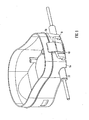
Figure 2 is a perspective view of an underside of a base of a bag according to the first embodiment; -
Figure 3 is a perspective view of a clip according to the first embodiment; -
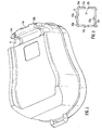
Figure 4 is a perspective view of an inside of a base according to the first embodiment; -
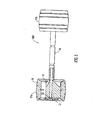
Figure 5 is a schematic illustration of the axle and wheel assembly of the first embodiment; -
Figures 6a and 6b are schematic plan views of a bag portion and a base portion, respectively of a golf bag according to the first embodiment; -
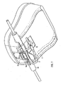
Figure 7 is a perspective view of an underside of a base of a bag according to the first embodiment showing the clip hooked to the latch; -
Figure 8 is a further perspective view of the base; -
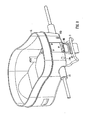
Figure 9 is a perspective view of the base showing the latch in a closed configuration whereby the clip is gripped by the latch; -
Figure 10 is a perspective view of an underside of the base showing the latch in a closed configuration; -
Figure 11 is a side view of a bag according to the first embodiment showing the latch in an open configuration; -
Figure 12 is a side view of a bag according to the first embodiment showing the latch in a closed configuration; -
Figure 13 illustrates a hand-grip according to the first embodiment; -
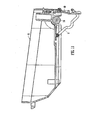
Figure 14 illustrates a foot extension according to a second embodiment of the invention; -
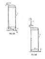
Figures 15a and 15b illustrate a foot plate structure according to the second embodiment of the invention; and -
Figure 16 is a side view of a golf bag according to the second embodiment showing the bag in an upright position (a) with wheels attached and (b) with wheels detached. - Referring to
Figure 1 , agolf bag 1 having similar dimensions to a standard lightweight golf carry bag comprises conventional supportinglegs 2 for supporting thebag 1 when not being supported by the golfer and which can be stored flat against the bag when not in use. Ahandle 3 comprising ashaft 4 and a hand-grip 5 extending substantially perpendicular to the shaft is provided, the shaft being extendable from a non-extended position. The bag also has abase 6, and two wheels 7a and 7b mounted at opposite ends of anaxle 16 which is removably attachable to thebase 6. - Referring to
Figure 2 , an underside of thebase 6 is shown with a channel-shapedrecess 8 extending across its width. This recess is formed adjacent to one of the shorter sides of the base. The axle is received into the recess and secured by a substantiallysquare metal clip 9 which is illustrated inFigure 3 . The clip has four sides (10a-d) with anopening 11 being provided within the middle of one side (10a) to form free ends 12a and 12b. These free ends are the point at which the clip is attached to thebase 6. In this embodiment the clip is shown (inFigure 7 ) as being centrally located on the base, although a plurality of smaller clips may be provided for example at positions across a width of the base. Theclip 9 is pivotable about its point of attachment to the base. This enables the clip to be moved toward and away from the base, and positioned across an axle which may be located within the recess. The sides of theclip arched regions channels sides -
Figure 4 illustrates an inner surface of thebase 6 which has a moldedspigot 15 for receiving the shaft of the handle (not shown). The shaft fits over the spigot and is glued and pinned in place. This spigot is centrally located above therecess 8 provided on the underside of the base. - The removable axle and wheel unit are illustrated in
Figure 5 . Theaxle 16 is molded from a plastics material and is shown withwheels 17a and 17b located at opposed ends. Each wheel comprises awheel hub 18, atyre 19, aspring washer 20 and ahub cap 21. A gap is provided between the axle and the hub sufficient to enable free rotation of the wheel. In some embodiments of the invention the gap is approximately 1 mm. - The
body portion 22 of the golf bag in which the golf clubs are retained (Figure 6 ) is molded as a single unit from a rigid plastics material. The body portion takes the form of a substantially hollow cylinder into which the golf clubs are placed with the heads of the clubs protruding from a top of the body portion. A closable flap 1A is provided at the top of the bag to prevent the clubs from falling out of the bag if the bag is tipped, for example when transported in a vehicle.Figure 6a is a top view of the body portion and showsribs 23 of a plastics material defining varying shaped and sizedchannels providing compartments 24 suitable for accommodating different golf clubs. The rigidity of the body portion prevents the bag from twisting under load and when being towed. - The body portion is molded so as to have an
apical region 25 which houses a substantially cylindrical,hollow shaft 26 into which theshaft 3 of the handle is inserted. - As noted above, an interior surface of the base portion, as shown in
Figure 6b is molded to incorporate a moldedspigot 15 for receiving the end portion of the shaft of the handle. Thus when the base portion and body portion are connected together an integrally molded hollow shaft for receiving the shaft of the handle is formed. The outer tube is molded into the head and into the base in order to create a stiff dynamic structure. - The means for attachment of the
axle 16 to thebase 6 is illustrated schematically infigures 7 to 12 . -
Clip 9 is pivotably attached to thebase 6 by means of ananchor 30 having a pair of laterally spacedcoaxial loops 32 arranged to receiveend portions clip 9 therethrough. - A
latch 40 is pivotably mounted to an end face 6B of the base. The latch is provided with a concave recessedportion 42 having a shape corresponding to that of the clip 9 (Figures 7 ,10 ). A portion ofedge 10d ofclip 9 is receivable in the recessedportion 42. The latch is arranged so that it may be swung into confronting relationship with end face 6B of thebase 6 thereby to hold theaxle 16 snugly and securely within the channel-shaped recess 8 (Figures 9 ,11 ). Thelatch 40 is configured to provide a snap-tight closure, resilience of theclip 9 assisting in providing the snap-tight action. In some embodiments of the invention resilience of thebase 6 assists in providing the strap-tight action. - In use, a golfer inserts golf clubs into
compartments 24 of thebody portion 22 and secures the flap 1A to prevent clubs from falling from the bag. Theaxle 16 with wheels mounted thereon may be removed from the bag by swinginglatch 40 away from the base and unhookingclip 9 from the latch. - The
clip 9 may be hooked back on to thelatch 40 and folded into juxtaposition with thebase 6 when theaxle 16 is removed. - The wheels may be removed for transportation of the
bag 1, for example during transportation in a vehicle, or to reduce a weight of the bag when carried by means of a shoulder strap. - When it is required to drag the bag along ground, the wheels may be reinstalled.
- Handle 3 (
figure 13 ) is used to pull the bag along the ground, and is extended from the bag when required. - According to a second embodiment of the invention, a golf bag is provided having removable wheels similar to those of the first embodiment, and further having a foot extension and a foot plate 27 (
Figures 13, 14 and15a, 15b ). - The
footplate 27 is a "live hinge" 30 (Figure 14 ). When attaching the wheels the golfer will unclip the upper surface of the foot plate and rotate it thereby allowing thelegs 28a/b to be erected from a flat position, the "T" heads 29a/b on theleg 28a/b locate inholes 29a/b on the upper surface and then 'click' into place holding the lower surface in an elevated position and hence providing the foot. After the wheels are removed the cycle is reversed to stow the lower surface, inconspicuously under the base of the bag. - When the wheel unit is attached to the base the bag is raised by about 50mm from the ground. In some embodiments of the invention the
foot extension 30 the leg actuation system, which is conventional to golf bags, to remain effective even when the base is raised above the ground and the length of the conventional spring element used to actuate the legs is of insufficient length. The foot extension, which is preferably manufactured from a plastics material, is fitted to the lower part of the leg actuation system and preferably clips on to the existing leg actuation system through a suitably molded slot system such that it can be pivoted towards the ground, being of sufficient length to contact the ground the foot extension replaces the function of the spring element. The foot extension is the spring foot and can swivel, clicking into place, to perform as an extension or can swivel back to an un-extended position where it performs at an appropriate length to suit a wheel-less bag. - However, the foot extension and foot plate mechanisms are not required in some embodiments of the invention, such as the first embodiment. This is because it is generally found to be more convenient to support the bag in a freestanding position in a tilted configuration as shown in
Figure 1 , using conventional supportinglegs 2, rather than in an upright condition. - It will be appreciated by those skilled in the art that the apparatus may be produced to any desired scale. For example, bags of the type herein described may be produced of a size suitable for adult use, or of a size suitable for use by children. In other words, a version for use by juniors (including children) is envisaged that is a scaled-down version of that used by adults.
- Throughout the description and claims of this specification, the singular encompasses the plural unless the context otherwise requires. In particular, where the indefinite article is used, the specification is to be understood as contemplating plurality as well as singularity, unless the context requires otherwise.
- Features, integers, characteristics, compounds, chemical moieties or groups described in conjunction with a particular aspect, embodiment or example of the invention are to be understood to be applicable to any other aspect, embodiment or example described herein unless incompatible therewith.
Claims (14)
- Apparatus comprising a bag (1) having a base (6) adapted to receive a ground rolling device (100), said ground rolling device being detachably connectable to the base and comprising an axle (16) provided with a wheel (7a,b) at or adjacent each end such that when the ground rolling device is connected to the base the wheels project laterally from either side of the base,
wherein the axle is received within a channel (8) that extends from one side of the base to the other side such that when the axle is connected to the base the wheels project beyond the edges of the base;
and wherein the channel is a recess formed in the underside of the base. - Apparatus as claimed in claim 1 wherein retaining means, preferably comprising a latch (40) and/or a clip (9), is provided to retain the axle within the recess.
- Apparatus as claimed in claim 2 wherein the latch is configured to co-operate with the clip to releasably secure the axle to the base and, preferably, wherein the clip is pivotably attached to the bag.
- Apparatus as claimed in claim 2 or claim 3 wherein the clip is configured to be pivotable to a position wherein the clip extends across a width of the channel thereby to secure the axle to the base.
- Apparatus as claimed in claim 4 wherein the latch is pivotably connected to the bag.
- Apparatus as claimed in any preceding claim wherein the bag is provided with support legs (2) pivotably coupled to a body portion of the bag, the support legs being movable between a retracted configuration and an extended configuration, preferably wherein in the retracted configuration the support legs are arranged to lie in juxtaposition with the body portion, and in the extended configuration the support legs are arranged to project away from the body portion.
- Apparatus as claimed in claim 6 wherein in the extended configuration, the legs in combination with the body portion define a tripod structure.
- Apparatus as claimed in claim 6 or claim 7 wherein the legs are movable between the retracted and extended configurations by means of a spring foot, wherein the spring foot preferably being arranged to facilitate opening of the legs when the spring foot is depressed against the ground and the apparatus preferably further comprising means for extending the spring foot towards the ground when the ground rolling device is connected to the base.
- Apparatus as claimed in any preceding claim, wherein the bag is further provided with a handle (3), preferably comprising a shaft (4) and a hand-grip (5), an an upper region of the bag and wherein said handle is extendable from a non-extended position to an extended position.
- Apparatus as claimed in claim 9, wherein at least a portion of the shaft is telescopic and/or wherein at least part of the handle is rotatable relative to a longitudinal axis of the bag.
- Apparatus as claimed in claim 9 or claim 10, wherein the shaft of the handle is located within a molded channel which extends at least pa rt of a length of the bag and preferably from the base of the bag, and the shaft is rotatable within said channel.
- Apparatus as claimed in any preceding claim further comprising a carry strap which is preferably a dual strap.
- Apparatus according to any preceding claim, wherein the bag is configured to store at least one golf club, fishing rod or gardening equipment.
- A ground rolling device (100) which is detachably connectable to a base (6) a golf bag (1), said ground rolling device comprising an axle (16) provided with a wheel (7a,b) or adjacent each end such that when said ground rolling device is connected to the base the wheels project laterally from either side of said base,
wherein the axle is receivable within a channel (8) that extends from one side of the base to the other side such that when the axle is connected to the base the wheels project beyond the edges of the base;
and wherein the channel is a recess formed in the underside of the base.
Applications Claiming Priority (3)
| Application Number | Priority Date | Filing Date | Title |
|---|---|---|---|
| GBGB0524632.7A GB0524632D0 (en) | 2005-12-02 | 2005-12-02 | Bag |
| US11/324,246 US7584972B2 (en) | 2005-12-02 | 2006-01-04 | Golf bag |
| PCT/GB2006/004506 WO2007063330A2 (en) | 2005-12-02 | 2006-12-04 | Bag |
Publications (2)
| Publication Number | Publication Date |
|---|---|
| EP1959783A2 EP1959783A2 (en) | 2008-08-27 |
| EP1959783B1 true EP1959783B1 (en) | 2011-11-23 |
Family
ID=35685968
Family Applications (1)
| Application Number | Title | Priority Date | Filing Date |
|---|---|---|---|
| EP06820392A Not-in-force EP1959783B1 (en) | 2005-12-02 | 2006-12-04 | Bag with wheels |
Country Status (5)
| Country | Link |
|---|---|
| US (1) | US7584972B2 (en) |
| EP (1) | EP1959783B1 (en) |
| AT (1) | ATE534309T1 (en) |
| GB (1) | GB0524632D0 (en) |
| WO (1) | WO2007063330A2 (en) |
Families Citing this family (15)
| Publication number | Priority date | Publication date | Assignee | Title |
|---|---|---|---|---|
| US9067614B2 (en) | 2005-04-25 | 2015-06-30 | M & C Innovations, Llc | Travel cooler with transitionable U-shaped handle |
| US9057552B2 (en) | 2008-12-11 | 2015-06-16 | M&C Innovations, LLC | Cooler having removable wheel assembly |
| US9835367B2 (en) | 2008-12-11 | 2017-12-05 | M & C Innovations, Llc | Cooler having removable wheel assembly |
| US9211901B2 (en) | 2008-12-11 | 2015-12-15 | M & C Innovations, Llc | Cooler having removable wheel assembly |
| US9022395B1 (en) * | 2011-06-17 | 2015-05-05 | M & C Innovations, Llc | Cooler having removable wheel assembly |
| US9211902B2 (en) | 2008-12-11 | 2015-12-15 | M & C Innovations, Llc | Cooler having removable wheel assembly |
| US8430265B2 (en) | 2008-12-11 | 2013-04-30 | M & C Innovations, Llc | Collapsible coolers |
| US8875964B1 (en) | 2011-06-16 | 2014-11-04 | M & C Innovations, Llc | Backpack collapsible coolers |
| US8695839B1 (en) | 2011-06-17 | 2014-04-15 | M & C Innovations, Llc | Cooler with wrap-around side cover |
| US20140167374A1 (en) * | 2012-03-08 | 2014-06-19 | Michael Henry Lenneman | Wheel kit attachment apparatus for hand operating golf bags and sport duffel bag |
| US8590906B1 (en) | 2012-07-27 | 2013-11-26 | Carlos E. Sanchez | Golf bag dolly assembly |
| DE202014101048U1 (en) | 2014-03-10 | 2014-06-30 | Sam Tung Tsui | Foldable multipurpose containers |
| TWI708900B (en) * | 2016-01-20 | 2020-11-01 | 奧地利商奧羅科技有限公司 | Rotary plain bearing, device having the rotary plain bearing, use of the device having the rotary plain bearing, and golf trolley |
| KR102051912B1 (en) * | 2019-07-29 | 2019-12-04 | 김용원 | Movable stand golf bag |
| US11738247B2 (en) * | 2020-04-21 | 2023-08-29 | Robert Chorne | Golf bag carrier with golf bag and base having detachable wheels |
Family Cites Families (17)
| Publication number | Priority date | Publication date | Assignee | Title |
|---|---|---|---|---|
| US1744414A (en) * | 1926-03-23 | 1930-01-21 | Joseph H Pflaum | Golf-bag attachment |
| US2629609A (en) * | 1951-08-06 | 1953-02-24 | Harry R Wilson | Wheeled golf bag |
| US4153264A (en) * | 1977-12-15 | 1979-05-08 | Pfister William J | Golf cart |
| IE54886B1 (en) * | 1984-05-02 | 1990-03-14 | Remplir Enterprises Ltd | A golf bag carrier |
| JPS6215369U (en) | 1985-07-10 | 1987-01-29 | ||
| US4900043A (en) | 1988-05-05 | 1990-02-13 | Kho Dick T | Wheel holding brackets attached to suitcases |
| US5193842A (en) * | 1992-03-18 | 1993-03-16 | Fontenot Joel K | Combined golf bag and cooler cart |
| US5351983A (en) * | 1993-04-20 | 1994-10-04 | Descalo Theresa A | Convertible dual golf cart |
| US6010101A (en) * | 1997-12-02 | 2000-01-04 | Spalding Sports Worldwide, Inc. | Automatic golf bag support stand |
| US6202808B1 (en) | 1999-07-28 | 2001-03-20 | Outrigger, Inc. | Rolling case with radially recessed roller |
| DE29922082U1 (en) | 1999-12-15 | 2000-03-16 | Unique Product & Design Co., Ltd., Yung Kang, Tainan | Golf cart |
| US6454281B1 (en) * | 2000-01-24 | 2002-09-24 | Stan Pearson | Bucket truck |
| US6460867B2 (en) * | 2000-02-07 | 2002-10-08 | Otto Sciulli | Golf cart |
| US6561527B2 (en) * | 2000-03-10 | 2003-05-13 | Spadino Daniel T | Hybrid golf bag technology |
| US6598889B1 (en) * | 2002-01-08 | 2003-07-29 | Po-Tang Su | Golf bag cart |
| US7114730B2 (en) * | 2003-05-20 | 2006-10-03 | Erkie, Inc. | Golf bag with detachable wheel assembly |
| US7416195B2 (en) * | 2004-10-04 | 2008-08-26 | David Craig Zwack | Compact caddy for compressed gas tanks |
-
2005
- 2005-12-02 GB GBGB0524632.7A patent/GB0524632D0/en not_active Ceased
-
2006
- 2006-01-04 US US11/324,246 patent/US7584972B2/en not_active Expired - Fee Related
- 2006-12-04 AT AT06820392T patent/ATE534309T1/en active
- 2006-12-04 WO PCT/GB2006/004506 patent/WO2007063330A2/en not_active Ceased
- 2006-12-04 EP EP06820392A patent/EP1959783B1/en not_active Not-in-force
Also Published As
| Publication number | Publication date |
|---|---|
| WO2007063330A3 (en) | 2007-09-07 |
| US7584972B2 (en) | 2009-09-08 |
| US20070126194A1 (en) | 2007-06-07 |
| WO2007063330A2 (en) | 2007-06-07 |
| ATE534309T1 (en) | 2011-12-15 |
| GB0524632D0 (en) | 2006-01-11 |
| EP1959783A2 (en) | 2008-08-27 |
Similar Documents
| Publication | Publication Date | Title |
|---|---|---|
| US7926835B2 (en) | Wheeled golf bag arrangement | |
| US7934729B2 (en) | Sports bag with integral transportation system | |
| US8764030B1 (en) | Sports bag with integral transportation system | |
| US6050592A (en) | Combined golf bag and collapsible golf cart | |
| EP0160575B1 (en) | A golf bag carrier | |
| US5829585A (en) | Golf club transporation device | |
| EP1959783A2 (en) | Bag | |
| US7114730B2 (en) | Golf bag with detachable wheel assembly | |
| US6056301A (en) | Golf bag having retractable wheels and handle | |
| US2883731A (en) | Buddy cart | |
| US2629609A (en) | Wheeled golf bag | |
| US7997594B1 (en) | Sports equipment caddy | |
| US11738247B2 (en) | Golf bag carrier with golf bag and base having detachable wheels | |
| US7997593B2 (en) | Blower cart | |
| US3883150A (en) | Golf club carrier | |
| WO2005120927A2 (en) | Sports bag with integral transportation system | |
| US8672342B2 (en) | Foldable cart for golf bag | |
| US6942238B1 (en) | Upright golf cart | |
| US20040216970A1 (en) | Fold-out wheeled support for long, wheeled travel case | |
| US7322434B1 (en) | Collapsible golf scooter cart having fold out balance wheels | |
| US3953045A (en) | Ferrett bag and cart | |
| US6311937B1 (en) | Golf bag with seating apparatus | |
| US6443405B1 (en) | Golf bag with seating apparatus | |
| US20070252353A1 (en) | Rollable golf bag | |
| US10080937B1 (en) | Self-centering counterbalanced walking cart |
Legal Events
| Date | Code | Title | Description |
|---|---|---|---|
| PUAI | Public reference made under article 153(3) epc to a published international application that has entered the european phase |
Free format text: ORIGINAL CODE: 0009012 |
|
| 17P | Request for examination filed |
Effective date: 20080702 |
|
| AK | Designated contracting states |
Kind code of ref document: A2 Designated state(s): AT BE BG CH CY CZ DE DK EE ES FI FR GB GR HU IE IS IT LI LT LU LV MC NL PL PT RO SE SI SK TR |
|
| 17Q | First examination report despatched |
Effective date: 20100806 |
|
| RTI1 | Title (correction) |
Free format text: BAG WITH WHEELS |
|
| GRAP | Despatch of communication of intention to grant a patent |
Free format text: ORIGINAL CODE: EPIDOSNIGR1 |
|
| DAX | Request for extension of the european patent (deleted) | ||
| GRAS | Grant fee paid |
Free format text: ORIGINAL CODE: EPIDOSNIGR3 |
|
| GRAA | (expected) grant |
Free format text: ORIGINAL CODE: 0009210 |
|
| AK | Designated contracting states |
Kind code of ref document: B1 Designated state(s): AT BE BG CH CY CZ DE DK EE ES FI FR GB GR HU IE IS IT LI LT LU LV MC NL PL PT RO SE SI SK TR |
|
| REG | Reference to a national code |
Ref country code: GB Ref legal event code: FG4D |
|
| REG | Reference to a national code |
Ref country code: CH Ref legal event code: EP |
|
| REG | Reference to a national code |
Ref country code: IE Ref legal event code: FG4D |
|
| REG | Reference to a national code |
Ref country code: DE Ref legal event code: R096 Ref document number: 602006026062 Country of ref document: DE Effective date: 20120119 |
|
| REG | Reference to a national code |
Ref country code: NL Ref legal event code: VDEP Effective date: 20111123 |
|
| LTIE | Lt: invalidation of european patent or patent extension |
Effective date: 20111123 |
|
| PG25 | Lapsed in a contracting state [announced via postgrant information from national office to epo] |
Ref country code: LT Free format text: LAPSE BECAUSE OF FAILURE TO SUBMIT A TRANSLATION OF THE DESCRIPTION OR TO PAY THE FEE WITHIN THE PRESCRIBED TIME-LIMIT Effective date: 20111123 Ref country code: IS Free format text: LAPSE BECAUSE OF FAILURE TO SUBMIT A TRANSLATION OF THE DESCRIPTION OR TO PAY THE FEE WITHIN THE PRESCRIBED TIME-LIMIT Effective date: 20120323 |
|
| PG25 | Lapsed in a contracting state [announced via postgrant information from national office to epo] |
Ref country code: SI Free format text: LAPSE BECAUSE OF FAILURE TO SUBMIT A TRANSLATION OF THE DESCRIPTION OR TO PAY THE FEE WITHIN THE PRESCRIBED TIME-LIMIT Effective date: 20111123 Ref country code: GR Free format text: LAPSE BECAUSE OF FAILURE TO SUBMIT A TRANSLATION OF THE DESCRIPTION OR TO PAY THE FEE WITHIN THE PRESCRIBED TIME-LIMIT Effective date: 20120224 Ref country code: LV Free format text: LAPSE BECAUSE OF FAILURE TO SUBMIT A TRANSLATION OF THE DESCRIPTION OR TO PAY THE FEE WITHIN THE PRESCRIBED TIME-LIMIT Effective date: 20111123 Ref country code: SE Free format text: LAPSE BECAUSE OF FAILURE TO SUBMIT A TRANSLATION OF THE DESCRIPTION OR TO PAY THE FEE WITHIN THE PRESCRIBED TIME-LIMIT Effective date: 20111123 Ref country code: BE Free format text: LAPSE BECAUSE OF FAILURE TO SUBMIT A TRANSLATION OF THE DESCRIPTION OR TO PAY THE FEE WITHIN THE PRESCRIBED TIME-LIMIT Effective date: 20111123 Ref country code: PT Free format text: LAPSE BECAUSE OF FAILURE TO SUBMIT A TRANSLATION OF THE DESCRIPTION OR TO PAY THE FEE WITHIN THE PRESCRIBED TIME-LIMIT Effective date: 20120323 Ref country code: NL Free format text: LAPSE BECAUSE OF FAILURE TO SUBMIT A TRANSLATION OF THE DESCRIPTION OR TO PAY THE FEE WITHIN THE PRESCRIBED TIME-LIMIT Effective date: 20111123 |
|
| PG25 | Lapsed in a contracting state [announced via postgrant information from national office to epo] |
Ref country code: CY Free format text: LAPSE BECAUSE OF FAILURE TO SUBMIT A TRANSLATION OF THE DESCRIPTION OR TO PAY THE FEE WITHIN THE PRESCRIBED TIME-LIMIT Effective date: 20111123 |
|
| PG25 | Lapsed in a contracting state [announced via postgrant information from national office to epo] |
Ref country code: CZ Free format text: LAPSE BECAUSE OF FAILURE TO SUBMIT A TRANSLATION OF THE DESCRIPTION OR TO PAY THE FEE WITHIN THE PRESCRIBED TIME-LIMIT Effective date: 20111123 Ref country code: MC Free format text: LAPSE BECAUSE OF NON-PAYMENT OF DUE FEES Effective date: 20111231 Ref country code: BG Free format text: LAPSE BECAUSE OF FAILURE TO SUBMIT A TRANSLATION OF THE DESCRIPTION OR TO PAY THE FEE WITHIN THE PRESCRIBED TIME-LIMIT Effective date: 20120223 Ref country code: DK Free format text: LAPSE BECAUSE OF FAILURE TO SUBMIT A TRANSLATION OF THE DESCRIPTION OR TO PAY THE FEE WITHIN THE PRESCRIBED TIME-LIMIT Effective date: 20111123 Ref country code: SK Free format text: LAPSE BECAUSE OF FAILURE TO SUBMIT A TRANSLATION OF THE DESCRIPTION OR TO PAY THE FEE WITHIN THE PRESCRIBED TIME-LIMIT Effective date: 20111123 Ref country code: EE Free format text: LAPSE BECAUSE OF FAILURE TO SUBMIT A TRANSLATION OF THE DESCRIPTION OR TO PAY THE FEE WITHIN THE PRESCRIBED TIME-LIMIT Effective date: 20111123 |
|
| REG | Reference to a national code |
Ref country code: CH Ref legal event code: PL |
|
| PG25 | Lapsed in a contracting state [announced via postgrant information from national office to epo] |
Ref country code: IT Free format text: LAPSE BECAUSE OF FAILURE TO SUBMIT A TRANSLATION OF THE DESCRIPTION OR TO PAY THE FEE WITHIN THE PRESCRIBED TIME-LIMIT Effective date: 20111123 Ref country code: RO Free format text: LAPSE BECAUSE OF FAILURE TO SUBMIT A TRANSLATION OF THE DESCRIPTION OR TO PAY THE FEE WITHIN THE PRESCRIBED TIME-LIMIT Effective date: 20111123 Ref country code: PL Free format text: LAPSE BECAUSE OF FAILURE TO SUBMIT A TRANSLATION OF THE DESCRIPTION OR TO PAY THE FEE WITHIN THE PRESCRIBED TIME-LIMIT Effective date: 20111123 |
|
| REG | Reference to a national code |
Ref country code: AT Ref legal event code: MK05 Ref document number: 534309 Country of ref document: AT Kind code of ref document: T Effective date: 20111123 |
|
| PLBE | No opposition filed within time limit |
Free format text: ORIGINAL CODE: 0009261 |
|
| STAA | Information on the status of an ep patent application or granted ep patent |
Free format text: STATUS: NO OPPOSITION FILED WITHIN TIME LIMIT |
|
| 26N | No opposition filed |
Effective date: 20120824 |
|
| PG25 | Lapsed in a contracting state [announced via postgrant information from national office to epo] |
Ref country code: LI Free format text: LAPSE BECAUSE OF NON-PAYMENT OF DUE FEES Effective date: 20111231 Ref country code: CH Free format text: LAPSE BECAUSE OF NON-PAYMENT OF DUE FEES Effective date: 20111231 |
|
| REG | Reference to a national code |
Ref country code: DE Ref legal event code: R097 Ref document number: 602006026062 Country of ref document: DE Effective date: 20120824 |
|
| PG25 | Lapsed in a contracting state [announced via postgrant information from national office to epo] |
Ref country code: AT Free format text: LAPSE BECAUSE OF FAILURE TO SUBMIT A TRANSLATION OF THE DESCRIPTION OR TO PAY THE FEE WITHIN THE PRESCRIBED TIME-LIMIT Effective date: 20111123 |
|
| PG25 | Lapsed in a contracting state [announced via postgrant information from national office to epo] |
Ref country code: ES Free format text: LAPSE BECAUSE OF FAILURE TO SUBMIT A TRANSLATION OF THE DESCRIPTION OR TO PAY THE FEE WITHIN THE PRESCRIBED TIME-LIMIT Effective date: 20120305 |
|
| PG25 | Lapsed in a contracting state [announced via postgrant information from national office to epo] |
Ref country code: LU Free format text: LAPSE BECAUSE OF NON-PAYMENT OF DUE FEES Effective date: 20111204 |
|
| PG25 | Lapsed in a contracting state [announced via postgrant information from national office to epo] |
Ref country code: FI Free format text: LAPSE BECAUSE OF FAILURE TO SUBMIT A TRANSLATION OF THE DESCRIPTION OR TO PAY THE FEE WITHIN THE PRESCRIBED TIME-LIMIT Effective date: 20111123 |
|
| PG25 | Lapsed in a contracting state [announced via postgrant information from national office to epo] |
Ref country code: TR Free format text: LAPSE BECAUSE OF FAILURE TO SUBMIT A TRANSLATION OF THE DESCRIPTION OR TO PAY THE FEE WITHIN THE PRESCRIBED TIME-LIMIT Effective date: 20111123 |
|
| PG25 | Lapsed in a contracting state [announced via postgrant information from national office to epo] |
Ref country code: HU Free format text: LAPSE BECAUSE OF FAILURE TO SUBMIT A TRANSLATION OF THE DESCRIPTION OR TO PAY THE FEE WITHIN THE PRESCRIBED TIME-LIMIT Effective date: 20111123 |
|
| PGFP | Annual fee paid to national office [announced via postgrant information from national office to epo] |
Ref country code: IE Payment date: 20131230 Year of fee payment: 8 Ref country code: GB Payment date: 20131202 Year of fee payment: 8 |
|
| PGFP | Annual fee paid to national office [announced via postgrant information from national office to epo] |
Ref country code: DE Payment date: 20131230 Year of fee payment: 8 |
|
| PGFP | Annual fee paid to national office [announced via postgrant information from national office to epo] |
Ref country code: FR Payment date: 20131220 Year of fee payment: 8 |
|
| REG | Reference to a national code |
Ref country code: DE Ref legal event code: R119 Ref document number: 602006026062 Country of ref document: DE |
|
| GBPC | Gb: european patent ceased through non-payment of renewal fee |
Effective date: 20141204 |
|
| REG | Reference to a national code |
Ref country code: IE Ref legal event code: MM4A |
|
| REG | Reference to a national code |
Ref country code: FR Ref legal event code: ST Effective date: 20150831 |
|
| PG25 | Lapsed in a contracting state [announced via postgrant information from national office to epo] |
Ref country code: GB Free format text: LAPSE BECAUSE OF NON-PAYMENT OF DUE FEES Effective date: 20141204 Ref country code: DE Free format text: LAPSE BECAUSE OF NON-PAYMENT OF DUE FEES Effective date: 20150701 Ref country code: IE Free format text: LAPSE BECAUSE OF NON-PAYMENT OF DUE FEES Effective date: 20141204 |
|
| PG25 | Lapsed in a contracting state [announced via postgrant information from national office to epo] |
Ref country code: FR Free format text: LAPSE BECAUSE OF NON-PAYMENT OF DUE FEES Effective date: 20141231 |