EP1959615A1 - Method and system for recovering from DRX timing de-synchronization in LTE-active - Google Patents
Method and system for recovering from DRX timing de-synchronization in LTE-active Download PDFInfo
- Publication number
- EP1959615A1 EP1959615A1 EP07102421A EP07102421A EP1959615A1 EP 1959615 A1 EP1959615 A1 EP 1959615A1 EP 07102421 A EP07102421 A EP 07102421A EP 07102421 A EP07102421 A EP 07102421A EP 1959615 A1 EP1959615 A1 EP 1959615A1
- Authority
- EP
- European Patent Office
- Prior art keywords
- drx
- continuous reception
- timing
- enb
- synchronization
- Prior art date
- Legal status (The legal status is an assumption and is not a legal conclusion. Google has not performed a legal analysis and makes no representation as to the accuracy of the status listed.)
- Granted
Links
Images




Classifications
-
- H—ELECTRICITY
- H04—ELECTRIC COMMUNICATION TECHNIQUE
- H04L—TRANSMISSION OF DIGITAL INFORMATION, e.g. TELEGRAPHIC COMMUNICATION
- H04L1/00—Arrangements for detecting or preventing errors in the information received
- H04L1/12—Arrangements for detecting or preventing errors in the information received by using return channel
- H04L1/16—Arrangements for detecting or preventing errors in the information received by using return channel in which the return channel carries supervisory signals, e.g. repetition request signals
- H04L1/18—Automatic repetition systems, e.g. Van Duuren systems
- H04L1/1867—Arrangements specially adapted for the transmitter end
- H04L1/188—Time-out mechanisms
-
- H—ELECTRICITY
- H04—ELECTRIC COMMUNICATION TECHNIQUE
- H04L—TRANSMISSION OF DIGITAL INFORMATION, e.g. TELEGRAPHIC COMMUNICATION
- H04L1/00—Arrangements for detecting or preventing errors in the information received
- H04L1/12—Arrangements for detecting or preventing errors in the information received by using return channel
- H04L1/16—Arrangements for detecting or preventing errors in the information received by using return channel in which the return channel carries supervisory signals, e.g. repetition request signals
- H04L1/18—Automatic repetition systems, e.g. Van Duuren systems
- H04L1/1812—Hybrid protocols; Hybrid automatic repeat request [HARQ]
-
- H—ELECTRICITY
- H04—ELECTRIC COMMUNICATION TECHNIQUE
- H04L—TRANSMISSION OF DIGITAL INFORMATION, e.g. TELEGRAPHIC COMMUNICATION
- H04L1/00—Arrangements for detecting or preventing errors in the information received
- H04L1/12—Arrangements for detecting or preventing errors in the information received by using return channel
- H04L2001/125—Arrangements for preventing errors in the return channel
-
- H—ELECTRICITY
- H04—ELECTRIC COMMUNICATION TECHNIQUE
- H04W—WIRELESS COMMUNICATION NETWORKS
- H04W76/00—Connection management
- H04W76/20—Manipulation of established connections
-
- H—ELECTRICITY
- H04—ELECTRIC COMMUNICATION TECHNIQUE
- H04W—WIRELESS COMMUNICATION NETWORKS
- H04W92/00—Interfaces specially adapted for wireless communication networks
- H04W92/04—Interfaces between hierarchically different network devices
- H04W92/10—Interfaces between hierarchically different network devices between terminal device and access point, i.e. wireless air interface
-
- Y—GENERAL TAGGING OF NEW TECHNOLOGICAL DEVELOPMENTS; GENERAL TAGGING OF CROSS-SECTIONAL TECHNOLOGIES SPANNING OVER SEVERAL SECTIONS OF THE IPC; TECHNICAL SUBJECTS COVERED BY FORMER USPC CROSS-REFERENCE ART COLLECTIONS [XRACs] AND DIGESTS
- Y02—TECHNOLOGIES OR APPLICATIONS FOR MITIGATION OR ADAPTATION AGAINST CLIMATE CHANGE
- Y02D—CLIMATE CHANGE MITIGATION TECHNOLOGIES IN INFORMATION AND COMMUNICATION TECHNOLOGIES [ICT], I.E. INFORMATION AND COMMUNICATION TECHNOLOGIES AIMING AT THE REDUCTION OF THEIR OWN ENERGY USE
- Y02D30/00—Reducing energy consumption in communication networks
- Y02D30/70—Reducing energy consumption in communication networks in wireless communication networks
Definitions
- the present disclosure relates generally to the long-term evolution (LTE) of third generation partnership project (3GPP), and in particular, to DRX timing de-synchronization in an LTE_ACTIVE state.
- LTE long-term evolution
- 3GPP third generation partnership project
- a UE can be in one of two radio resource control (RRC) states. These are LTE_IDLE and LTE_ACTIVE.
- RRC radio resource control
- the UE can be configured for discontinuous reception (DRX) in both the LTE_IDLE and the LTE_ACTIVE states.
- DRX discontinuous reception
- the DRX allows the UE to synchronize its listening period to a known paging cycle of the network. By synchronizing the listening period, the UE can turn off its radio transceiver during the standby period, thereby significantly saving battery resources.
- DRX parameters allow the mobile to synchronize with the network and to know that it will not receive another signal until a specified time has elapsed.
- DRX also be used when the UE is in LTE_ACTIVE state. It is further proposed that when in discontinuous reception (DRX) by the user equipment (UE) in LTE_ACTIVE state, that a regular DRX configuration is signaled by a radio resource control (RRC) protocol message and a temporary DRX (re)configuration is signaled by medium access control (MAC) signaling, for example, in the MAC protocol data unit (MAC-PDU) header or MAC control PDU.
- RRC radio resource control
- MAC medium access control
- the eNB Before user data is sent on a downlink shared channel, the eNB will send a scheduling indication on the downlink shared control channel (DLSCCH) providing the parameters that the UE will use to demodulate the data. However, if the UE misses that DLSCCH scheduling indication, the UE will not know to receive the user data and, hence, will not know to acknowledge (ACK) or negatively ACK (NACK) the user MAC-PDU. The eNB will be awaiting the ACK or NACK, i.e. hybrid ARQ (HARQ), response. When it does not get that response, it is considered a discontinuous transmission (DTX).
- DLSCCH downlink shared control channel
- HARQ hybrid ARQ
- a MAC-PDU may be lost.
- UE automatically increments DRX length according to a rule, e.g. no data activities in a certain duration, the eNB will maintain its current DRX value while the UE will increment its own DRX value. This results in DRX timing de-synchronization, i.e. the eNB and the UE are operating on different DRX periods.
- the eNB has to determine the UE DRX timing in order to send new data to the UE.
- the eNB may achieve this by sending various probing messages to the UE at those times when it knows the UE may possibly be awake. It will, after a few attempts, find the UE DRX timing, and awaken the UE in order to regain synchronization.
- the eNB may transmit a scheduling indication on the DLSCCH and transmits MAC-PDUs on the DL-SCH at the time when the UE should be awake. If the eNB gets no hybrid automatic repeat request (HARQ) feedback signals from the UE, the eNB may consider that the UE is out of synchronization in DRX timing. In order to recover from such a state, two methods are described below.
- HARQ hybrid automatic repeat request
- a first method may be the indication of DRX timing de-synchronization in system information.
- the eNB may broadcast the radio network temporary identifiers (RNTI) of the UE in a predefined system information block.
- RNTI radio network temporary identifiers
- the UE may read the system information block.
- the UE may deactivate the DRX mode and transmits Continuous Reception Notification messages using L1/L2 signaling or MAC signaling to the eNB.
- the eNB may retransmit the data waiting in its buffer to the UE.
- the eNB may remove the RNTI from the system information.
- a method for recovering from DRX de-synchronization may be to pre-configure an absolute wake up time.
- absolute wake up timing can be indicated to the UE by the RRC.
- the absolute wake-up timing may be defined by the radio frame offset (ARFoff) to the system radio frame timing and DRX interval (Alnt).
- ARFoff radio frame offset
- Alnt DRX interval
- the eNB may send a Continuous Reception Command (i.e. DRX deactivation) in L1/L2 signaling or MAC signaling to the UE at the absolute wake up time.
- a Continuous Reception Command i.e. DRX deactivation
- L1/L2 signaling or MAC signaling L1/L2 signaling or MAC signaling
- the UE may check if a Continuous Reception Command is received or not. If so, the UE may turn on the power on the transceiver, goes back to continuous reception, obtains the uplink synchronization and scheduling grant if necessary, and sends a Continuous Reception Response to the eNB.
- the eNB On reception of the Continuous Reception Response, the eNB may transmit the data in its buffer to the UE.
- the eNB may send the Continuous Reception Command over the L1/L2 signaling channel, which contains an indication that uplink synchronization should be readjusted and the information regarding the dedicated uplink resource allocated for Continuous Reception Response.
- the UE may readjust the uplink timing and responds by sending Continuous Reception Command using the resource indicated in the Continuous Reception Command.
- the absolute wake up radio frame offset can be calculated from the UE identities such as IMSI (International Mobile Station Identity) in a similar manner that paging occasion is calculated in UMTS as described in 3GPP TS25.304.
- the DRX interval may be included in the system information rather than signaled via dedicated RRC messages.
- the present disclosure therefore may provide a method for recovering from discontinuous reception (DRX) timing de-synchronization in an LTE_ACTIVE state comprising the steps of: detecting DRX timing de-synchronization; transmitting an indicator to a User Equipment (UE) to resume continuous reception; and waiting for an indication of whether a Continuous Reception Response was received.
- DRX discontinuous reception
- the present disclosure may further provide a method for going to continuous reception in User Equipment due to a discontinuous reception (DRX) timing de-synchronization in an LTE_ACTIVE state comprising the steps of: waking up from DRX; checking an indicator to determine whether to go to continuous reception; and if an indicator exists to go to continuous reception, deactivating DRX, going to continuous reception and transmitting a continuous reception response.
- DRX discontinuous reception
- the present disclosure may further provide an enhanced Node B (eNB) adapted to recover from discontinuous reception (DRX) timing de-synchronization in an LTE_ACTIVE state, characterized by: means for detecting DRX timing de-synchronization; means for transmitting an indicator to a User Equipment (UE) to resume Continuous Reception; and means for waiting for an indication of whether a Continuous Reception Response was received.
- eNB enhanced Node B
- UE User Equipment
- the present disclosure may further provide User Equipment (UE) adapted to go to continuous reception due to a discontinuous reception (DRX) timing de-synchronization in an LTE_ACTIVE state, characterized by: means for waking up from DRX; means for checking an indicator to determine whether to go to continuous reception; and means for deactivating DRX, going to continuous reception and transmitting a Continuous Reception Response if an indicator exists to go to continuous reception.
- UE User Equipment
- DRX discontinuous reception
- FIG. 1 shows a block diagram illustrating the long-term evolution (LTE) user plane protocol stack.
- LTE long-term evolution
- a UE 110 communicates with both an evolved Node B (eNB) 120 and an access gateway (aGW) 130.
- eNB evolved Node B
- aGW access gateway
- the packet data convergence protocol (PDCP) layer 140 is illustrated both on the UE 110 and on aGW 130.
- the PDCP layer 140 performs internet protocol (IP) header compression and decompression, encryption of user data, transfer of user data and maintenance of sequence numbers (SN) for radio bearers.
- IP internet protocol
- radio link control protocol layer 142 which communicates with the radio link control protocol layer 142 on the eNB 120. As will be appreciated, communication occurs through the physical layer in protocol stacks such as those illustrated in Figures 1 and 2 . However, RLC-PDUs from the RLC layer 142 of the UE are interpreted by the RLC layer 142 on the eNB 120.
- MAC medium access control
- the layer 1 (L1) LTE (physical layer 148) is below the RLC/MAC layers 144 and 146. This layer is the physical layer for communications.
- Figure 2 illustrates the LTE control plane protocol architecture. Similar reference numerals to those used in Figure 1 will be used in Figure 2 .
- UE 110 communicates with eNB 120 and aGW 130.
- physical layer 148, MAC layer 146, RLC layer 142 and PDCP layer 140 exist within Figure 2 .
- FIG. 2 also shows the non-access stratum (NAS) layer 210.
- NAS layer 210 could include mobility management and session management.
- the radio resource control protocol layer (RRC) 220 is the part of the protocol stack that is responsible for the assignment, configuration and release of radio resources between the UE and the E-UTRAN (Evolved universal terrestrial radio access network).
- RRC protocol layer Evolved universal terrestrial radio access network.
- the basic functionalities of RRC protocol for LTE is described in 3GPP TR25.813.
- ARQ automatic repeat request
- RLC radio link control
- RNC radio network controller
- LTE Long Term Evolution
- eNB a tighter interaction may exist between the ARQ and the HARQ (within the MAC layer, also located in the eNB).
- Very efficient signaling procedures for activating and de-activating DRX and specifying the duration of DRX periods are required in order to support a large population of UEs in a cell that are utilizing DRX in an LTE_ACTIVE state.
- the evolved Node B eNB
- the UE cannot receive the data. Therefore, special effort is required to ensure the UE and the eNB are synchronized regarding when DRX is activated and deactivated.
- the indication between the eNB and the UE can be explicitly signaled by the radio resource control (RRC) or layer 1/layer 2 (L1/L2) signaling.
- RRC radio resource control
- L1/L2 layer 1/layer 2
- a more efficient solution is to include an optional field in the MAC header of a MAC-PDU (MAC Protocol Data Unit) or a MAC control PDU (MAC PDU which contains only MAC control information) to indicate DRX activation and deactivation.
- the field preferably indicates the DRX value and timing margin for activation and deactivation. A value of zero, for example, could mean DRX deactivation in the DRX value field in a preferred embodiment.
- the eNB may extend the MAC header field to include a DRX length initial value. For example, this could be 320 milliseconds.
- DRX period within the MAC-PDU header
- three bits may be added to the MAC header to indicate eight values of the DRX period.
- a bit value from 000 to 111 could indicate one of eight discrete values.
- a smaller field in the MAC header could be used (for example two bits) to indicate increment or decrement.
- the RRC could indicate default values, and if the MAC header indicates increment or decrement then the UE could change to the pre-specified value, according to the received indication.
- the RRC could define the mapping between the actual DRX value and the value contained in the smaller field.
- the UE acknowledges it to the eNB by transmitting HARQ ACK and starts the DRX at the appropriate system frame considering propagation delay and processing delay at the eNB.
- the eNB receives the ACK from the UE, it also starts the DRX at the appropriate system frame time.
- the eNB does not turn off its transceiver, but simply knows not to transmit messages to the individual UE.
- the eNB can send a MAC-PDU with a header extension set to DRX deactivation or a shorter DRX length depending on the amount of data in the buffer or the quality of service requirements.
- the UE reconfigures the DRX accordingly and acknowledges the MAC-PDU.
- the eNB receives the ACK, it reconfigures the DRX.
- the deactivation could be accomplished by merely setting the length value to zero.
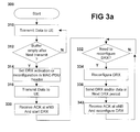
- Figure 3a shows an exemplary method for controlling DRX activation in the LTE_ACTIVE state.
- the process starts at step 300 and proceeds to step 310 in which data is transmitted to the UE.
- data transmission in the LTE_ACTIVE state utilizes the MAC-PDU at the data link layer to transmit the data.
- step 312 a check is made to see whether the buffer of data to be sent to the UE will be empty after the next transmit. If no, the process proceeds back to step 310 in which data is transmitted to the UE. Alternatively, if the buffer will be empty after the next transmit and the data arrival rate is lower than a threshold value, the process proceeds to step 314.
- the eNB sets DRX activation in the MAC-PDU header. As indicated above, this includes a DRX activation value indicating the length of the DRX period and DRX activation time if needed, e.g., the system radio frame number when the DRX activation should be performed. In another embodiment the eNB may simply indicate an increase in the DRX interval.
- the UE reconfigures the existing DRX interval to a predetermined reduced interval.
- the predetermined interval may be either known to both eNB and UE or pre-signaled to the UE from the eNB via explicit signaling; either by system broadcast or RRC signaling.
- step 316 the data including the modified MAC-PDU header is sent to the UE.
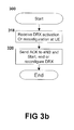
- step 318 the UE receives the data and sees that DRX activation is specified in the MAC-PDU header.
- the process proceeds to step 320 in which the UE sends an acknowledgement (ACK) to the eNB and starts the DRX at the appropriate system frame considering propagation delay and processing delay at the eNB. If the activation time of the specified DRX is indicated in the received MAC-PDU header, both the UE and the eNB apply the new DRX value at that time.
- ACK acknowledgement
- step 330 of Figure 3a the eNB receives the ACK from the UE and starts the DRX at the same appropriate system frame.
- the DRX can continue until various events occur which may require the DRX to be adjusted.
- One event is the reception of data from the aGW by the eNB for the UE.
- the DRX can either be deactivated or the period of the DRX can be reduced.
- Other events that may require the adjustment of the DRX include a change of signal power level between the eNB and the UE or possibly a gradual increase in the DRX cycle due to continued data inactivity, among others.
- step 332 the eNB checks to see whether the DRX needs to be adjusted. As indicated above, this could be the situation where data is received to be sent to the UE. Here the DRX can either be deactivated or the period adjusted.
- step 332 if the DRX does not need to be adjusted, the process proceeds back to step 332 and continues to check whether or not the DRX needs to be adjusted.
- step 332 finds that the DRX does need to be adjusted, the process proceeds to step 334 in which it adjusts the DRX. This could be deactivating the DRX by transmitting a zero value for the DRX or a shorter DRX or a longer DRX as required.
- the MAC-PDU with the modified header (including modified DRX value and the activation time for new DRX value if needed) is sent to the UE in step 336.
- the MAC-PDU in step 336 could also include any data that has been received by the eNB that needs to be transmitted to the UE. If no data is included then the MAC-PDU is considered a MAC control PDU.
- step 318 the process then proceeds to step 318 in which the MAC-PDU with modified header is received at the UE.
- the UE recognizes the DRX period is to be adjusted and in step 320 it sends an acknowledgement to the eNB and it adjusts its DRX period at the appropriate system frame considering propagation delay and processing delay as at the eNB. If the activation time is indicated in the MAC-PDU header, both the UE and the eNB apply the new DRX value at that time.
- step 342 the eNB receives the ACK and starts the modified DRX period at the same appropriate system frame. The process then proceeds back to step 332 to see whether the DRX needs to be adjusted again.
- the transmitter's hybrid automatic repeat request (HARQ) entity which is a variation of the ARQ error control method, does not always properly demodulate an ACK or a NACK possibly due to poor channel conditions. Thus, in some situations, one can be interpreted as the other.
- HARQ hybrid automatic repeat request
- an ACK to NACK or NACK to ACK misinterpretation needs to be handled as misinterpretation of control information signaled between an eNB and a UE can lead to loss of data or possibly radio connection.
- a further consideration is the incremental extension of the DRX.
- the rules are carried in the RRC RB set-up/reconfiguration or measurement control messages to the UE. In this case, if no data is received after N current DRX cycles, the eNB and the UE increase the DRX length to the next larger value automatically. This eliminates the need for signaling between the eNB and the UE to increase the DRX length and therefore saves network and battery resources.
- the eNB When the eNB determines that the UE is out of synchronization within its DRX timing, the eNB shows the RNTI of the UE in the predefined system information block. When the UE wakes up, it reads the system information block. If the RNTI of the UE is indicated, the UE deactivates the DRX mode and transmits a Continuous Reception Notification message using L1/L2 signaling or MAC signaling to the eNB. On reception of the Continuous Reception Notification message, the eNB will retransmit the data waiting in the buffer to the UE. When the data is acknowledged or HARQ feedback from the UE is received, the eNB removes the RNTI from the system information.
- Figure 4a shows a flow chart for a method of signaling the RNTI in the system information to recover from DRX de-synchronization. The process starts at step 410.
- step 412 the eNB transmits the next MAC-PDU.
- step 414 it checks whether a DRX timing de-synchronization has occurred. As indicated above, this could be if the eNB gets no HARQ feedback signals from the UE, in which case the eNB may consider that the UE is out of synchronization in DRX timing.
- step 414 If no DRX timing de-synchronization is detected in step 414, the process proceeds back to step 412 continues until a DRX timing de-synchronization is detected.
- step 414 If a DRX timing de-synchronization is detected in step 414, the process proceeds to step 416 in which the RNTI of the UE is added to a predefined system information block.
- the UE when waking up from DRX, will check the system information and detect its RNTI, as described with reference to Figure 4b below.
- step 416 in Figure 4a the process then waits for a Continuous Reception Notification message. If a Continuous Reception Notification message is received in step 418, the process proceeds to step 420 in which it retransmits the MAC-PDU. As will be appreciated, this may be the same MAC-PDU that the eNB attempted to transmit in step 412 before a DRX timing de-synchronization was detected in step 414. The retransmission of the MAC-PDU occurs in step 420.
- step 422 it checks whether a success or HARQ feedback is received.
- step 418 If, in step 418, a Continuous Reception Notification message is not received, or in step 422 if success or HARQ feedback is not received, the process proceeds to step 430 in which a check is made to see whether a handover has occurred or whether the RRC connection is released.
- step 430 If a handover to another cell is detected or the RRC connection is found released in step 430, the process proceeds to step 435 in which the RNTI of the UE is removed from the predefined system information block. Similarly, if success is achieved or HARQ feedback is received from step 422, the process proceeds to step 435 in which the RNTI of the UE is removed from the predefined system information block.
- step 435 proceeds from step 435 to step 440 in which it is ended.
- step 430 if handover to another cell or the RRC connection release is found in step 430, the process proceeds to step 440 in which it is ended.
- step 452 the UE wakes up from DRX.
- step 454 the UE receives data if indicated on the downlink shared control channels (DLSCCHs) and performs measurements or other functions as required.
- DLSCCHs downlink shared control channels
- step 456 it reads a pre-defined system information block for a list of UEs in DRX timing de-synchronization.
- step 460 it checks whether the RNTI of the UE is included in the list of UEs in the system information block. If no, the UE proceeds back to DRX in step 462 and then waits for the DRX wake up in step 452.
- step 460 if the RNTI of the UE is included in the system information block, the process proceeds to step 466 in which DRX is deactivated and continuous reception is started.
- step 468 in which a Continuous Reception Notification is transmitted and the process ends in step 470.
- the de-synchronization is therefore recovered at the next DRX cycle by the UE detecting its RNTI in the predefined system information block.
- an absolute wake up time can be notified to the UE by RRC.
- the absolute wake up timing is defined by the radio frame offset (ARFoff) to the system radio frame timing and DRX interval (AINT). Regardless of the current DRX setting, the UE must wake up at the radio frame of ARFoff + N * Alnt where N is an integer.
- the process starts at step 510 and proceeds to step 512 in which the next MAC-PDU is transmitted.
- step 514 the eNB checks to see whether timing de-synchronization for DRX has occurred. As indicated above, this could occur based on the lack of receipt of HARQ feedback from the UE.
- step 514 If DRX timing de-synchronization is not detected in step 514, the process proceeds back to step 512 and continues transmitting the next MAC-PDU.
- step 514 if DRX timing de-synchronization is detected, the process proceeds to step 520 in which a Continuous Reception Command is transmitted at the absolute wake up time configured by the radio resource control.
- step 522 it checks whether a Continuous Reception Response was received from the UE. If yes, the process proceeds to step 524 in which the MAC-PDU from step 512 for which no HARQ feedback was received is retransmitted in step 524.
- step 526 it checks whether there has been success or whether HARQ feedback was received. If yes, the process ends at step 530.
- step 522 Continuous Reception Response was not received or, from step 526, the HARQ feedback was not received or no success was determined
- the process proceeds to step 540 in which a check is made to see whether a handover has occurred or the RRC connection has been released. If it is determined in step 540 that a handover has occurred or the RRC connection has been released, the process proceeds to step 530 and ends.
- step 540 If, in step 540, it is determined that no handover has occurred or the RRC connection has been released, then the process proceeds to step 542 in which it checks whether a retry period is over. If no, then the process proceeds back to step 520. If yes, the process proceeds to step 544 in which the RRC connection is released and the process then ends at step 530.
- step 550 the process starts at step 550 and proceeds to step 552 in which the UE wakes up from a DRX.
- step 552 the UE wakes up from a DRX.
- step 554 it receives data if indicated on the downlink shared control channels (DLSCCHs) and performs measurements or other functions if required.
- DLSCCHs downlink shared control channels
- step 556 the process checks whether the time is an absolute wake up time. If yes, the process proceeds to step 558, which the UE checks whether a Continuous Reception Command has been received.
- step 556 if it is not an absolutely wake up time or step 558, if not Continuous Reception Command has been received, the process proceeds to step 560 in which the UE goes back into DRX. From step 560, the process continues by waking up from DRX in step 552.
- step 558 if a Continuous Reception Command is received in step 558, the process proceeds to step 570 in which DRX is de-activated and continuous reception is started. The process then proceeds to step 572 in which the Continuous Reception Response is transmitted and the process ends at step 574.
- the eNB when the eNB detects that the UE is out of synchronization in DRX timing, the eNB sends a Continuous Reception Command in L1/L2 signaling or MAC signaling to the UE at an absolute wake up time.
- the UE wakes up at the absolute wake up time, checks if a Continuous Reception Command is received or not, and if yes, the UE turns on the power to its transceivers and goes back into continuous reception.
- the absolute wake up radio frame offset ARFoff can be calculated from the UE identities such as IMSI in a similar manner that the paging occasion is calculated in UMTS which is described in 3GPP TS25.304.
- the DRX interval may be included in the system information rather than saved via dedicated RRC messages.
- the benefit of signaling the ARFoff to the UE is that the eNB could align the absolute wake up time with the current DRX setting so that further battery savings can be achieved.
Landscapes
- Engineering & Computer Science (AREA)
- Computer Networks & Wireless Communication (AREA)
- Signal Processing (AREA)
- Mobile Radio Communication Systems (AREA)
- Hardware Redundancy (AREA)
- Medicines Containing Plant Substances (AREA)
- Tunnel Furnaces (AREA)
- Detection And Prevention Of Errors In Transmission (AREA)
- Cephalosporin Compounds (AREA)
- Synchronisation In Digital Transmission Systems (AREA)
- Train Traffic Observation, Control, And Security (AREA)
Abstract
Description
- The present disclosure relates generally to the long-term evolution (LTE) of third generation partnership project (3GPP), and in particular, to DRX timing de-synchronization in an LTE_ACTIVE state.
- In the long-term evolution infrastructure, a UE can be in one of two radio resource control (RRC) states. These are LTE_IDLE and LTE_ACTIVE.
- The UE can be configured for discontinuous reception (DRX) in both the LTE_IDLE and the LTE_ACTIVE states. In the LTE_IDLE state, the DRX allows the UE to synchronize its listening period to a known paging cycle of the network. By synchronizing the listening period, the UE can turn off its radio transceiver during the standby period, thereby significantly saving battery resources. DRX parameters allow the mobile to synchronize with the network and to know that it will not receive another signal until a specified time has elapsed.
- It is proposed at the 3GPP TSG-RAN working group that DRX also be used when the UE is in LTE_ACTIVE state. It is further proposed that when in discontinuous reception (DRX) by the user equipment (UE) in LTE_ACTIVE state, that a regular DRX configuration is signaled by a radio resource control (RRC) protocol message and a temporary DRX (re)configuration is signaled by medium access control (MAC) signaling, for example, in the MAC protocol data unit (MAC-PDU) header or MAC control PDU.
- In LTE, before user data is sent on a downlink shared channel, the eNB will send a scheduling indication on the downlink shared control channel (DLSCCH) providing the parameters that the UE will use to demodulate the data. However, if the UE misses that DLSCCH scheduling indication, the UE will not know to receive the user data and, hence, will not know to acknowledge (ACK) or negatively ACK (NACK) the user MAC-PDU. The eNB will be awaiting the ACK or NACK, i.e. hybrid ARQ (HARQ), response. When it does not get that response, it is considered a discontinuous transmission (DTX). If the data indication on the downlink shared control channel (DLSCCH) is missed by the UE and the subsequent discontinuous transmit (DTX) on the HARQ feedback channel is misinterpreted as an ACK by the enhanced node B (eNB), a MAC-PDU may be lost. Moreover, if UE automatically increments DRX length according to a rule, e.g. no data activities in a certain duration, the eNB will maintain its current DRX value while the UE will increment its own DRX value. This results in DRX timing de-synchronization, i.e. the eNB and the UE are operating on different DRX periods.
- As will be appreciated, this increases the downlink message delivery latency and wastes downlink radio resources. Longer delivery latency should be avoided, especially for critical downlink control messages. Once DRX timing de-synchronization occurs, the eNB has to determine the UE DRX timing in order to send new data to the UE. The eNB may achieve this by sending various probing messages to the UE at those times when it knows the UE may possibly be awake. It will, after a few attempts, find the UE DRX timing, and awaken the UE in order to regain synchronization.
- In the case that the UE is in LTE_ACTIVE and DRX is activated, on the arrival of downlink data the eNB may transmit a scheduling indication on the DLSCCH and transmits MAC-PDUs on the DL-SCH at the time when the UE should be awake. If the eNB gets no hybrid automatic repeat request (HARQ) feedback signals from the UE, the eNB may consider that the UE is out of synchronization in DRX timing. In order to recover from such a state, two methods are described below.
- A first method may be the indication of DRX timing de-synchronization in system information. Specifically, when the eNB detects that the UE is out of synchronization in DRX timing, the eNB may broadcast the radio network temporary identifiers (RNTI) of the UE in a predefined system information block. When the UE wakes up, it may read the system information block. If the RNTI of the UE is indicated, the UE may deactivate the DRX mode and transmits Continuous Reception Notification messages using L1/L2 signaling or MAC signaling to the eNB. On reception of the Continuous Reception Notification message, the eNB may retransmit the data waiting in its buffer to the UE. When the data is acknowledged or the HARQ feedback from the UE is received, the eNB may remove the RNTI from the system information.
- In a further embodiment, a method for recovering from DRX de-synchronization may be to pre-configure an absolute wake up time. Specifically, when a radio bearer for the interactive or background communication is established or DRX is activated on that bearer; absolute wake up timing can be indicated to the UE by the RRC. The absolute wake-up timing may be defined by the radio frame offset (ARFoff) to the system radio frame timing and DRX interval (Alnt). Regardless of the current DRX setting, the UE must wake up at the radio frame of ARFoff + N * Alnt, where N = 0, 1,... If the eNB wants to guarantee the recovery within 2.56 seconds, then the Alnt may be set to 2.56 seconds.
- When the eNB detects that the UE is out of synchronization in DRX timing, the eNB may send a Continuous Reception Command (i.e. DRX deactivation) in L1/L2 signaling or MAC signaling to the UE at the absolute wake up time. When the UE wakes up at the absolute wake up time, it may check if a Continuous Reception Command is received or not. If so, the UE may turn on the power on the transceiver, goes back to continuous reception, obtains the uplink synchronization and scheduling grant if necessary, and sends a Continuous Reception Response to the eNB. On reception of the Continuous Reception Response, the eNB may transmit the data in its buffer to the UE.
- In case the eNB wants the UE to readjust the uplink synchronization, the eNB may send the Continuous Reception Command over the L1/L2 signaling channel, which contains an indication that uplink synchronization should be readjusted and the information regarding the dedicated uplink resource allocated for Continuous Reception Response. Upon reception of such Continuous Reception Command, the UE may readjust the uplink timing and responds by sending Continuous Reception Command using the resource indicated in the Continuous Reception Command.
- In a further alternative embodiment, the absolute wake up radio frame offset can be calculated from the UE identities such as IMSI (International Mobile Station Identity) in a similar manner that paging occasion is calculated in UMTS as described in 3GPP TS25.304. In this case, the DRX interval may be included in the system information rather than signaled via dedicated RRC messages.
- The present disclosure therefore may provide a method for recovering from discontinuous reception (DRX) timing de-synchronization in an LTE_ACTIVE state comprising the steps of: detecting DRX timing de-synchronization; transmitting an indicator to a User Equipment (UE) to resume continuous reception; and waiting for an indication of whether a Continuous Reception Response was received.
- The present disclosure may further provide a method for going to continuous reception in User Equipment due to a discontinuous reception (DRX) timing de-synchronization in an LTE_ACTIVE state comprising the steps of: waking up from DRX; checking an indicator to determine whether to go to continuous reception; and if an indicator exists to go to continuous reception, deactivating DRX, going to continuous reception and transmitting a continuous reception response.
- The present disclosure may further provide an enhanced Node B (eNB) adapted to recover from discontinuous reception (DRX) timing de-synchronization in an LTE_ACTIVE state, characterized by: means for detecting DRX timing de-synchronization; means for transmitting an indicator to a User Equipment (UE) to resume Continuous Reception; and means for waiting for an indication of whether a Continuous Reception Response was received.
- The present disclosure may further provide User Equipment (UE) adapted to go to continuous reception due to a discontinuous reception (DRX) timing de-synchronization in an LTE_ACTIVE state, characterized by: means for waking up from DRX; means for checking an indicator to determine whether to go to continuous reception; and means for deactivating DRX, going to continuous reception and transmitting a Continuous Reception Response if an indicator exists to go to continuous reception.
- The present disclosure will be better understood with reference to the drawings in which:
-
Figure 1 is a block diagram showing a long-term evolution user plane protocol stack; -
Figure 2 is a block diagram showing a long-term evolution control plane protocol stack; -
Figure 3a is a flow chart showing a method to activate, deactivate and reconfigure a DRX period using a MAC-PDU header or MAC control PDU from the eNB side; -
Figure 3b is a flow chart showing a method to acknowledge deactivation, deactivation or reconfiguration of DRX period from the UE side; -
Figure 4a is a flow chart showing a method for indicating DRX timing de-synchronization within the system information from the eNB side; -
Figure 4b is a flow chart showing a method of realizing DRX timing de-synchronization within the system information from a UE side; -
Figure 5a is a flow chart showing a method of preconfigured wake up time recovery from possible DRX timing de-synchronizations from the eNB perspective; and -
Figure 5b is a flow chart showing a method for preconfigured wake up time recovery from possible DRX timing de-synchronization from the UE perspective. - Reference is now made to the drawings.
Figure 1 shows a block diagram illustrating the long-term evolution (LTE) user plane protocol stack. - A UE 110 communicates with both an evolved Node B (eNB) 120 and an access gateway (aGW) 130.
- Various layers are illustrated in the protocol stack. The packet data convergence protocol (PDCP)
layer 140 is illustrated both on the UE 110 and on aGW 130. ThePDCP layer 140 performs internet protocol (IP) header compression and decompression, encryption of user data, transfer of user data and maintenance of sequence numbers (SN) for radio bearers. - Below the
PDCP layer 140 is the radio linkcontrol protocol layer 142, which communicates with the radio linkcontrol protocol layer 142 on theeNB 120. As will be appreciated, communication occurs through the physical layer in protocol stacks such as those illustrated inFigures 1 and2 . However, RLC-PDUs from theRLC layer 142 of the UE are interpreted by theRLC layer 142 on theeNB 120. - Below
RLC layer 142 is the medium access control (MAC) datacommunication protocol layer 146. As will be appreciated by those skilled in the art, the RLC and MAC protocols form the data link sublayers of the LTE radio interface and reside on the eNB in LTE and user equipment. - The layer 1 (L1) LTE (physical layer 148) is below the RLC/MAC layers 144 and 146. This layer is the physical layer for communications.
- Referring to
Figure 2, Figure 2 illustrates the LTE control plane protocol architecture. Similar reference numerals to those used inFigure 1 will be used inFigure 2 . Specifically,UE 110 communicates witheNB 120 andaGW 130. Further,physical layer 148,MAC layer 146,RLC layer 142 andPDCP layer 140 exist withinFigure 2 . -
Figure 2 also shows the non-access stratum (NAS)layer 210. As will be appreciated,NAS layer 210 could include mobility management and session management. - The radio resource control protocol layer (RRC) 220, is the part of the protocol stack that is responsible for the assignment, configuration and release of radio resources between the UE and the E-UTRAN (Evolved universal terrestrial radio access network). The basic functionalities of RRC protocol for LTE is described in 3GPP TR25.813.
- As will be appreciated by those skilled in the art, in UMTS, automatic repeat request (ARQ) functionality is carried out within the RLC layer which resides in the radio network controller (RNC). Long Term Evolution (LTE) moves the ARQ functionality from the RNC to eNB where a tighter interaction may exist between the ARQ and the HARQ (within the MAC layer, also located in the eNB).
- Various issues regarding DRX in an LTE-ACTIVE state are considered herein.
- Very efficient signaling procedures for activating and de-activating DRX and specifying the duration of DRX periods are required in order to support a large population of UEs in a cell that are utilizing DRX in an LTE_ACTIVE state.
- As will be appreciated by those skilled in the art, if the evolved Node B (eNB) transmits data to the UE during its receiver off period due to a DRX operation, the UE cannot receive the data. Therefore, special effort is required to ensure the UE and the eNB are synchronized regarding when DRX is activated and deactivated.
- The indication between the eNB and the UE can be explicitly signaled by the radio resource control (RRC) or layer 1/layer 2 (L1/L2) signaling. As will be appreciated, however, explicit signaling may not be as efficient as desired.
- A more efficient solution is to include an optional field in the MAC header of a MAC-PDU (MAC Protocol Data Unit) or a MAC control PDU (MAC PDU which contains only MAC control information) to indicate DRX activation and deactivation. The field preferably indicates the DRX value and timing margin for activation and deactivation. A value of zero, for example, could mean DRX deactivation in the DRX value field in a preferred embodiment. Conversely, if data that is to be transmitted in the next MAC-PDU is the last one in the buffer for the UE, the eNB may extend the MAC header field to include a DRX length initial value. For example, this could be 320 milliseconds.
- Several different methods for signaling the DRX period within the MAC-PDU header can be envisaged. For example, three bits may be added to the MAC header to indicate eight values of the DRX period. Thus, rather than a specific time value being sent, a bit value from 000 to 111 could indicate one of eight discrete values.
- In an alternative, a smaller field in the MAC header could be used (for example two bits) to indicate increment or decrement. The RRC could indicate default values, and if the MAC header indicates increment or decrement then the UE could change to the pre-specified value, according to the received indication. Similarly, the RRC could define the mapping between the actual DRX value and the value contained in the smaller field.
- Once the UE receives the DRX value, it acknowledges it to the eNB by transmitting HARQ ACK and starts the DRX at the appropriate system frame considering propagation delay and processing delay at the eNB. When the eNB receives the ACK from the UE, it also starts the DRX at the appropriate system frame time. As will be appreciated, the eNB does not turn off its transceiver, but simply knows not to transmit messages to the individual UE.
- During the awake cycle of a DRX period, if new data has arrived at the eNB for transmission, the eNB can send a MAC-PDU with a header extension set to DRX deactivation or a shorter DRX length depending on the amount of data in the buffer or the quality of service requirements. The UE reconfigures the DRX accordingly and acknowledges the MAC-PDU. When the eNB receives the ACK, it reconfigures the DRX. As indicated above, the deactivation could be accomplished by merely setting the length value to zero.
- Reference is now made to
Figure 3a and3b .Figure 3a shows an exemplary method for controlling DRX activation in the LTE_ACTIVE state. The process starts atstep 300 and proceeds to step 310 in which data is transmitted to the UE. As will be appreciated by those skilled in the art, data transmission in the LTE_ACTIVE state utilizes the MAC-PDU at the data link layer to transmit the data. - The process next proceeds to step 312 in which a check is made to see whether the buffer of data to be sent to the UE will be empty after the next transmit. If no, the process proceeds back to step 310 in which data is transmitted to the UE. Alternatively, if the buffer will be empty after the next transmit and the data arrival rate is lower than a threshold value, the process proceeds to step 314.
- In
step 314, the eNB sets DRX activation in the MAC-PDU header. As indicated above, this includes a DRX activation value indicating the length of the DRX period and DRX activation time if needed, e.g., the system radio frame number when the DRX activation should be performed. In another embodiment the eNB may simply indicate an increase in the DRX interval. The UE reconfigures the existing DRX interval to a predetermined reduced interval. The predetermined interval may be either known to both eNB and UE or pre-signaled to the UE from the eNB via explicit signaling; either by system broadcast or RRC signaling. - The process then proceeds to step 316 in which the data including the modified MAC-PDU header is sent to the UE.
- Reference is now made to
Figure 3b . Instep 318, the UE receives the data and sees that DRX activation is specified in the MAC-PDU header. The process proceeds to step 320 in which the UE sends an acknowledgement (ACK) to the eNB and starts the DRX at the appropriate system frame considering propagation delay and processing delay at the eNB. If the activation time of the specified DRX is indicated in the received MAC-PDU header, both the UE and the eNB apply the new DRX value at that time. - In
step 330 ofFigure 3a , the eNB receives the ACK from the UE and starts the DRX at the same appropriate system frame. - As will be appreciated, the DRX can continue until various events occur which may require the DRX to be adjusted. One event is the reception of data from the aGW by the eNB for the UE. Depending on the amount of data received, the DRX can either be deactivated or the period of the DRX can be reduced. Other events that may require the adjustment of the DRX include a change of signal power level between the eNB and the UE or possibly a gradual increase in the DRX cycle due to continued data inactivity, among others.
- In
step 332 the eNB checks to see whether the DRX needs to be adjusted. As indicated above, this could be the situation where data is received to be sent to the UE. Here the DRX can either be deactivated or the period adjusted. - From
step 332, if the DRX does not need to be adjusted, the process proceeds back to step 332 and continues to check whether or not the DRX needs to be adjusted. - Once the process in
step 332 finds that the DRX does need to be adjusted, the process proceeds to step 334 in which it adjusts the DRX. This could be deactivating the DRX by transmitting a zero value for the DRX or a shorter DRX or a longer DRX as required. - The MAC-PDU with the modified header (including modified DRX value and the activation time for new DRX value if needed) is sent to the UE in
step 336. The MAC-PDU instep 336 could also include any data that has been received by the eNB that needs to be transmitted to the UE. If no data is included then the MAC-PDU is considered a MAC control PDU. - Referring to
Figure 3b , the process then proceeds to step 318 in which the MAC-PDU with modified header is received at the UE. The UE recognizes the DRX period is to be adjusted and instep 320 it sends an acknowledgement to the eNB and it adjusts its DRX period at the appropriate system frame considering propagation delay and processing delay as at the eNB. If the activation time is indicated in the MAC-PDU header, both the UE and the eNB apply the new DRX value at that time. - Referring to
Figure 3a , instep 342 the eNB receives the ACK and starts the modified DRX period at the same appropriate system frame. The process then proceeds back to step 332 to see whether the DRX needs to be adjusted again. - As will be appreciated by those skilled in the art, one issue with the above occurs in the case of a misinterpretation of an ACK or a NACK. Specifically, the transmitter's hybrid automatic repeat request (HARQ) entity, which is a variation of the ARQ error control method, does not always properly demodulate an ACK or a NACK possibly due to poor channel conditions. Thus, in some situations, one can be interpreted as the other. By having the DRX activation and deactivation occur in the MAC-PDU header, an ACK to NACK or NACK to ACK misinterpretation needs to be handled as misinterpretation of control information signaled between an eNB and a UE can lead to loss of data or possibly radio connection.
- A further consideration is the incremental extension of the DRX. Rules that dictate how the DRX period can be incremented or decremented (e.g. by factors of two), in a preferred embodiment, can be signaled during the radio bearer (RB) set up. The rules are carried in the RRC RB set-up/reconfiguration or measurement control messages to the UE. In this case, if no data is received after N current DRX cycles, the eNB and the UE increase the DRX length to the next larger value automatically. This eliminates the need for signaling between the eNB and the UE to increase the DRX length and therefore saves network and battery resources.
- When the eNB determines that the UE is out of synchronization within its DRX timing, the eNB shows the RNTI of the UE in the predefined system information block. When the UE wakes up, it reads the system information block. If the RNTI of the UE is indicated, the UE deactivates the DRX mode and transmits a Continuous Reception Notification message using L1/L2 signaling or MAC signaling to the eNB. On reception of the Continuous Reception Notification message, the eNB will retransmit the data waiting in the buffer to the UE. When the data is acknowledged or HARQ feedback from the UE is received, the eNB removes the RNTI from the system information.
- Reference is now made to
Figure 4a. Figure 4a shows a flow chart for a method of signaling the RNTI in the system information to recover from DRX de-synchronization. The process starts atstep 410. - The process proceeds to step 412 in which the eNB transmits the next MAC-PDU.
- The process then proceeds to step 414 in which it checks whether a DRX timing de-synchronization has occurred. As indicated above, this could be if the eNB gets no HARQ feedback signals from the UE, in which case the eNB may consider that the UE is out of synchronization in DRX timing.
- If no DRX timing de-synchronization is detected in
step 414, the process proceeds back to step 412 continues until a DRX timing de-synchronization is detected. - If a DRX timing de-synchronization is detected in
step 414, the process proceeds to step 416 in which the RNTI of the UE is added to a predefined system information block. As will be appreciated, the UE, when waking up from DRX, will check the system information and detect its RNTI, as described with reference toFigure 4b below. - From
step 416 inFigure 4a , the process then waits for a Continuous Reception Notification message. If a Continuous Reception Notification message is received instep 418, the process proceeds to step 420 in which it retransmits the MAC-PDU. As will be appreciated, this may be the same MAC-PDU that the eNB attempted to transmit instep 412 before a DRX timing de-synchronization was detected instep 414. The retransmission of the MAC-PDU occurs instep 420. - The process then proceeds to step 422 in which it checks whether a success or HARQ feedback is received.
- If, in
step 418, a Continuous Reception Notification message is not received, or instep 422 if success or HARQ feedback is not received, the process proceeds to step 430 in which a check is made to see whether a handover has occurred or whether the RRC connection is released. - If a handover to another cell is detected or the RRC connection is found released in
step 430, the process proceeds to step 435 in which the RNTI of the UE is removed from the predefined system information block. Similarly, if success is achieved or HARQ feedback is received fromstep 422, the process proceeds to step 435 in which the RNTI of the UE is removed from the predefined system information block. - The process then proceeds from
step 435 to step 440 in which it is ended. - Alternatively, if handover to another cell or the RRC connection release is found in
step 430, the process proceeds to step 440 in which it is ended. - Reference is now made to
Figure 4b . On the UE side, the process starts atstep 450. - In
step 452, the UE wakes up from DRX. - The process then proceeds to step 454 in which the UE receives data if indicated on the downlink shared control channels (DLSCCHs) and performs measurements or other functions as required.
- The process then proceeds to step 456 in which it reads a pre-defined system information block for a list of UEs in DRX timing de-synchronization.
- The process then proceeds to step 460 in which it checks whether the RNTI of the UE is included in the list of UEs in the system information block. If no, the UE proceeds back to DRX in
step 462 and then waits for the DRX wake up instep 452. - Alternatively, from
step 460, if the RNTI of the UE is included in the system information block, the process proceeds to step 466 in which DRX is deactivated and continuous reception is started. - The process then proceeds to step 468 in which a Continuous Reception Notification is transmitted and the process ends in
step 470. - As will be appreciated from the above, the de-synchronization is therefore recovered at the next DRX cycle by the UE detecting its RNTI in the predefined system information block.
- In a further embodiment, when a radio bearer for the interactive or background communication is established or DRX is activated on that bearer, an absolute wake up time can be notified to the UE by RRC. The absolute wake up timing is defined by the radio frame offset (ARFoff) to the system radio frame timing and DRX interval (AINT). Regardless of the current DRX setting, the UE must wake up at the radio frame of ARFoff + N * Alnt where N is an integer. Reference is now made to
Figure 5a . - The process starts at
step 510 and proceeds to step 512 in which the next MAC-PDU is transmitted. - The process then proceeds to step 514 in which the eNB checks to see whether timing de-synchronization for DRX has occurred. As indicated above, this could occur based on the lack of receipt of HARQ feedback from the UE.
- If DRX timing de-synchronization is not detected in
step 514, the process proceeds back to step 512 and continues transmitting the next MAC-PDU. - From
step 514, if DRX timing de-synchronization is detected, the process proceeds to step 520 in which a Continuous Reception Command is transmitted at the absolute wake up time configured by the radio resource control. - The process then proceeds to step 522 in which it checks whether a Continuous Reception Response was received from the UE. If yes, the process proceeds to step 524 in which the MAC-PDU from
step 512 for which no HARQ feedback was received is retransmitted instep 524. - The process then proceeds to step 526 in which it checks whether there has been success or whether HARQ feedback was received. If yes, the process ends at
step 530. - If, from
step 522, Continuous Reception Response was not received or, fromstep 526, the HARQ feedback was not received or no success was determined, the process proceeds to step 540 in which a check is made to see whether a handover has occurred or the RRC connection has been released. If it is determined instep 540 that a handover has occurred or the RRC connection has been released, the process proceeds to step 530 and ends. - If, in
step 540, it is determined that no handover has occurred or the RRC connection has been released, then the process proceeds to step 542 in which it checks whether a retry period is over. If no, then the process proceeds back tostep 520. If yes, the process proceeds to step 544 in which the RRC connection is released and the process then ends atstep 530. - Reference is now made to
Figure 5b . From the UE perspective, the process starts atstep 550 and proceeds to step 552 in which the UE wakes up from a DRX. The process then proceeds to step 554 in which it receives data if indicated on the downlink shared control channels (DLSCCHs) and performs measurements or other functions if required. - The process then proceeds to step 556 in which it checks whether the time is an absolute wake up time. If yes, the process proceeds to step 558, which the UE checks whether a Continuous Reception Command has been received.
- From
step 556, if it is not an absolutely wake up time or step 558, if not Continuous Reception Command has been received, the process proceeds to step 560 in which the UE goes back into DRX. Fromstep 560, the process continues by waking up from DRX instep 552. - Alternatively, if a Continuous Reception Command is received in
step 558, the process proceeds to step 570 in which DRX is de-activated and continuous reception is started. The process then proceeds to step 572 in which the Continuous Reception Response is transmitted and the process ends atstep 574. - Based on the above, when the eNB detects that the UE is out of synchronization in DRX timing, the eNB sends a Continuous Reception Command in L1/L2 signaling or MAC signaling to the UE at an absolute wake up time. The UE wakes up at the absolute wake up time, checks if a Continuous Reception Command is received or not, and if yes, the UE turns on the power to its transceivers and goes back into continuous reception.
- In a further alternative, the absolute wake up radio frame offset ARFoff can be calculated from the UE identities such as IMSI in a similar manner that the paging occasion is calculated in UMTS which is described in 3GPP TS25.304. In such a case, the DRX interval may be included in the system information rather than saved via dedicated RRC messages.
- As will be appreciated, the benefit of signaling the ARFoff to the UE is that the eNB could align the absolute wake up time with the current DRX setting so that further battery savings can be achieved.
- The embodiments described herein are examples of structures, systems or methods having elements corresponding to elements of the techniques of this disclosure. This description may enable those skilled in the art to use embodiments having alternatives elements that likewise correspond to the elements or the techniques of this disclosure. The intended scope of the techniques of this disclosure thus include other structures, systems or methods that do not differ from the techniques of this disclosure as described herein, and further include other structures, systems or methods with insubstantial differences from the techniques of this disclosure as described herein.
Claims (27)
- A method in a wireless communication system for recovering from discontinuous reception 'DRX' timing de-synchronization in an LTE_ACTIVE state comprising the steps of:detecting (414,514) DRX timing de-synchronization;transmitting (416,520) an indicator to a User Equipment 'UE' to resume continuous reception; andwaiting (418, 522) for an indication of whether a Continuous Reception Response or Continuous Reception Notification was received.
- The method of claim 1, wherein the transmitting step comprises adding a radio network temporarily identifier 'RNTI' for the User Equipment to a predefined system information block.
- The method of claim 2, wherein said detecting step comprises:sending or retransmitting a medium access control protocol data unit 'MAC-PDU' to the UE; andfailing to receive a hybrid automatic repeat request 'HARQ' feedback signal within a predetermined time.
- The method of claim 3, further comprising the steps of:receiving (418) the indication of the Continuous Reception Notification; andretransmitting (420) the MAC-PDU.
- The method of claim 4, further comprising the step of:removing (435) the RNTI for the User Equipment from the predefined system information block upon confirmation that the MAC-PDU was received.
- The method of claim 1, wherein the transmitting step comprises:waiting from an absolute wake-up time; andsending (520) a Continuous Reception Command.
- The method of claim 6, wherein said detecting step comprises:sending or retransmitting a medium access control protocol data unit 'MAC-PDU' to the UE; andfailing to receive a hybrid automatic repeat request 'HARQ' feedback signal within a predetermined time.
- The method of claim 7, further comprising the steps of:receiving (522) the indication of the Continuous Reception Response; andretransmitting (524) the MAC-PDU.
- The method of claim 8, further comprising the steps of:if the indication of the Continuous Reception Response is not received, or if the retransmission of the MAC-PDU is unsuccessful, checking (540) whether a handover has occurred or if an RRC connection has been released, and if yes, ending (530) the process.
- The method of claim 9, wherein if a handover has not occurred and if an RRC connection has been not been released, checking (542) whether a retry period is over, and
if yes, releasing the RRC connection (544); and
if no, repeating the waiting and sending steps (520). - The method of any one of claims 6 to 10, wherein absolute wake-up timing is defined by a radio frame offset to the system radio frame timing and DRX interval.
- The method of claim 11, wherein the absolute wake-up timing is a radio frame defined by the radio frame offset, added to the DRX interval multiplied by a positive integer or zero.
- The method of claim 12, wherein absolute wake-up timing is transmitted to the UE by RRC.
- The method of claim 12 or claim 13, wherein the radio frame offset is calculated from a subscriber or UE identitiy.
- The method of claim 14, wherein the identity is an International Mobile Station Identity.
- A method for going to continuous reception in a User Equipment due to a discontinuous reception 'DRX' timing de-synchronization in an LTE_ACTIVE state comprising the steps of:waking up from DRX(452, 552);checking (460, 558) an indicator to determine whether to go to continuous reception; andif an indicator exists to go to continuous reception, deactivating DRX (466, 570), going to continuous reception, and transmitting (468, 572) a Continuous Reception Response or Continuous Reception Notification.
- The method of claim 16, wherein the checking step comprises:reading (456) a predefined system information block; anddetermining (460) whether a radio network temporarily identifier 'RNTI' for the User Equipment is within the predefined system information block,
wherein if the determining step finds the RNTI of the User Equipment in the predefined system information block, checking step finds the indicator exists. - The method of claim 16 or claim 17, wherein, if an indicator exists to go to continuous reception and to obtain uplink synchronization, obtaining an uplink synchronization and scheduling grant for sending a Continuous Reception Response.
- The method of claim 16, wherein the checking step comprises:determining (556, 558) whether a Continuous Reception Command is received at an absolute wake-up time,wherein if the Continuous Reception Command is received at an absolute wake-up time the checking step find the indicator exists.
- An enhanced Node B 'eNB' adapted to recover from discontinuous reception 'DRX' timing de-synchronization in an LTE_ACTIVE state, comprising:means for detecting DRX timing de-synchronization;means for transmitting an indicator to a User Equipment 'UE' to resume continuous reception; andmeans for waiting for an indication of whether a Continuous Reception Response or Continuous Reception Notification was received.
- The eNB of claim 20, wherein the means for transmitting an indicator to the UE is adapted to include, in the indicator, a need for uplink synchronization and radio resource to be used for a Continuous Command Response.
- The eNB of claim 20 or claim 21, wherein the means for transmitting is adapted to add a radio network temporarily identifier 'RNTI' for the User Equipment to a predefined system information block.
- The eNB of claim 20 or claim 21, wherein the means for transmitting is adapted to:wait from an absolute wake-up time; andsend a Continuous Reception Command.
- A User Equipment 'UE' adapted to go to continuous reception due to a discontinuous reception 'DRX' timing de-synchronization in an LTE_ACTIVE state, comprising:means for waking up from DRX;means for checking an indicator to determine whether to go to continuous reception; andmeans for deactivating DRX, going to continuous reception and transmitting a Continuous Reception Response or Continuous Reception Notification if an indicator exists to go to continuous reception.
- The UE of claim 24, wherein the means for checking is adapted to:read a predefined system information block; anddetermine whether a radio network temporarily identifier 'RNTI' for the User Equipment is within the predefined system information block,
wherein if the RNTI of the User Equipment in the predefined system information block, the means for checking step is adapted to find the indicator exists. - The UE of claim 24, wherein the means for checking is adapted to determine whether a Continuous Reception Command is received at an absolute wake-up time,
wherein if the Continuous Reception Command is received at an absolute wake-up time the means for checking is adapted to find the indicator exists. - A wireless communication system comprising at least one enhanced Node B as claimed in any one of claims 20 to 23 and a plurality of User Equipments as claimed in any one of claims 24 to 26.
Priority Applications (31)
| Application Number | Priority Date | Filing Date | Title |
|---|---|---|---|
| ES09177680T ES2695900T3 (en) | 2007-02-14 | 2007-02-14 | Method and system for the recovery of a DRX desynchronization in an LTE_ACTIVE |
| HUE18189245A HUE055361T2 (en) | 2007-02-14 | 2007-02-14 | Method and system for recovering from drx timing de-synchronization in lte-active |
| AT07102421T ATE456226T1 (en) | 2007-02-14 | 2007-02-14 | METHOD AND SYSTEM FOR RECOVERY AFTER DRX TIMING DESYNCHRONIZATION IN LTE_ACTIVE |
| PT181892456T PT3419206T (en) | 2007-02-14 | 2007-02-14 | Method and system for recovering from drx timing de-synchronization in lte-active |
| ES18189245T ES2884548T3 (en) | 2007-02-14 | 2007-02-14 | Method and system to recover from DRX timing desync on LTE_active |
| PL18189245T PL3419206T3 (en) | 2007-02-14 | 2007-02-14 | Method and system for recovering from drx timing de-synchronization in lte-active |
| ES18189244T ES2776457T3 (en) | 2007-02-14 | 2007-02-14 | Method and system to recover from DRX timing desynchronization in LTE-ACTIVE |
| HUE18189244A HUE047799T2 (en) | 2007-02-14 | 2007-02-14 | Method and system for recovering from drx timing de-synchronization in lte-active |
| DK18189244.9T DK3419205T3 (en) | 2007-02-14 | 2007-02-14 | PROCEDURE AND RECOVERY SYSTEM AFTER DRX TIMING DESYNCHRONIZATION IN LTE-ACTIVE |
| DK20156754.2T DK3687092T3 (en) | 2007-02-14 | 2007-02-14 | METHOD AND SYSTEM FOR RECOVERY AFTER DRX-TIMING DISINCONRINATION IN LTE-ACTIVE |
| EP20156754.2A EP3687092B1 (en) | 2007-02-14 | 2007-02-14 | Method and system for recovering from drx timing de-synchronization in lte-active |
| EP18189245.6A EP3419206B1 (en) | 2007-02-14 | 2007-02-14 | Method and system for recovering from drx timing de-synchronization in lte-active |
| EP18189244.9A EP3419205B1 (en) | 2007-02-14 | 2007-02-14 | Method and system for recovering from drx timing de-synchronization in lte-active |
| ES20156754T ES2896957T3 (en) | 2007-02-14 | 2007-02-14 | Method and system to recover from DRX timing desync on LTE_active |
| PL18189244T PL3419205T3 (en) | 2007-02-14 | 2007-02-14 | Method and system for recovering from drx timing de-synchronization in lte-active |
| EP09177680.7A EP2161887B1 (en) | 2007-02-14 | 2007-02-14 | Method and system for recovering from DRX timing de-synchronization in LTE-Active |
| PT09177680T PT2161887T (en) | 2007-02-14 | 2007-02-14 | Method and system for recovering from drx timing de-synchronization in lte-active |
| DK09177680.7T DK2161887T3 (en) | 2007-02-14 | 2007-02-14 | PROCEDURE AND RESET SETTING AFTER DRX TIMING DESYNCHRONIZATION IN LTE-ACTIVE |
| DK18189245.6T DK3419206T3 (en) | 2007-02-14 | 2007-02-14 | PROCEDURE AND RETURN SYSTEM FROM DRX TIMING DESYCHRONIZATION IN LTE ACTIVE |
| PT181892449T PT3419205T (en) | 2007-02-14 | 2007-02-14 | Method and system for recovering from drx timing de-synchronization in lte-active |
| DE602007004434T DE602007004434D1 (en) | 2007-02-14 | 2007-02-14 | Method and system for recovering after a DRX timing desynchronization in LTE_Active |
| PL09177680T PL2161887T3 (en) | 2007-02-14 | 2007-02-14 | Method and system for recovering from DRX timing de-synchronization in LTE-Active |
| EP21191356.1A EP3926874B1 (en) | 2007-02-14 | 2007-02-14 | Method and system for recovering from drx timing de-synchronization in lte-active |
| EP07102421A EP1959615B1 (en) | 2007-02-14 | 2007-02-14 | Method and system for recovering from DRX timing de-synchronization in LTE-active |
| CA002677834A CA2677834A1 (en) | 2007-02-14 | 2008-02-12 | Method and system for recovering from drx timing de-synchronization in lte_active |
| JP2009549345A JP5243453B2 (en) | 2007-02-14 | 2008-02-12 | Method and system for recovering from DRX timing asynchronous in LTE_ACTIVE |
| CN201210563005.6A CN103036659B (en) | 2007-02-14 | 2008-02-12 | For the method and system from the asynchronous middle recovery of DRX timing in LTE_ACTIVE state |
| PCT/CA2008/000261 WO2008098352A1 (en) | 2007-02-14 | 2008-02-12 | Method and system for recovering from drx timing de-synchronization in lte_active |
| CN2008800115563A CN101653032B (en) | 2007-02-14 | 2008-02-12 | Method and system for recovering from DRX timing out-of-sync in LTE_ACTIVE |
| HK08111218.5A HK1116958B (en) | 2008-10-09 | Method and system for recovering from drx timing de-synchronization in lte-active | |
| JP2012089466A JP5417479B2 (en) | 2007-02-14 | 2012-04-10 | Method and system for recovering from DRX timing asynchronous in LTE_ACTIVE |
Applications Claiming Priority (1)
| Application Number | Priority Date | Filing Date | Title |
|---|---|---|---|
| EP07102421A EP1959615B1 (en) | 2007-02-14 | 2007-02-14 | Method and system for recovering from DRX timing de-synchronization in LTE-active |
Related Child Applications (5)
| Application Number | Title | Priority Date | Filing Date |
|---|---|---|---|
| EP18189245.6A Division EP3419206B1 (en) | 2007-02-14 | 2007-02-14 | Method and system for recovering from drx timing de-synchronization in lte-active |
| EP18189244.9A Division EP3419205B1 (en) | 2007-02-14 | 2007-02-14 | Method and system for recovering from drx timing de-synchronization in lte-active |
| EP21191356.1A Division EP3926874B1 (en) | 2007-02-14 | 2007-02-14 | Method and system for recovering from drx timing de-synchronization in lte-active |
| EP20156754.2A Division EP3687092B1 (en) | 2007-02-14 | 2007-02-14 | Method and system for recovering from drx timing de-synchronization in lte-active |
| EP09177680.7A Division EP2161887B1 (en) | 2007-02-14 | 2007-02-14 | Method and system for recovering from DRX timing de-synchronization in LTE-Active |
Publications (2)
| Publication Number | Publication Date |
|---|---|
| EP1959615A1 true EP1959615A1 (en) | 2008-08-20 |
| EP1959615B1 EP1959615B1 (en) | 2010-01-20 |
Family
ID=38123810
Family Applications (6)
| Application Number | Title | Priority Date | Filing Date |
|---|---|---|---|
| EP09177680.7A Active EP2161887B1 (en) | 2007-02-14 | 2007-02-14 | Method and system for recovering from DRX timing de-synchronization in LTE-Active |
| EP18189244.9A Active EP3419205B1 (en) | 2007-02-14 | 2007-02-14 | Method and system for recovering from drx timing de-synchronization in lte-active |
| EP18189245.6A Active EP3419206B1 (en) | 2007-02-14 | 2007-02-14 | Method and system for recovering from drx timing de-synchronization in lte-active |
| EP20156754.2A Active EP3687092B1 (en) | 2007-02-14 | 2007-02-14 | Method and system for recovering from drx timing de-synchronization in lte-active |
| EP21191356.1A Active EP3926874B1 (en) | 2007-02-14 | 2007-02-14 | Method and system for recovering from drx timing de-synchronization in lte-active |
| EP07102421A Active EP1959615B1 (en) | 2007-02-14 | 2007-02-14 | Method and system for recovering from DRX timing de-synchronization in LTE-active |
Family Applications Before (5)
| Application Number | Title | Priority Date | Filing Date |
|---|---|---|---|
| EP09177680.7A Active EP2161887B1 (en) | 2007-02-14 | 2007-02-14 | Method and system for recovering from DRX timing de-synchronization in LTE-Active |
| EP18189244.9A Active EP3419205B1 (en) | 2007-02-14 | 2007-02-14 | Method and system for recovering from drx timing de-synchronization in lte-active |
| EP18189245.6A Active EP3419206B1 (en) | 2007-02-14 | 2007-02-14 | Method and system for recovering from drx timing de-synchronization in lte-active |
| EP20156754.2A Active EP3687092B1 (en) | 2007-02-14 | 2007-02-14 | Method and system for recovering from drx timing de-synchronization in lte-active |
| EP21191356.1A Active EP3926874B1 (en) | 2007-02-14 | 2007-02-14 | Method and system for recovering from drx timing de-synchronization in lte-active |
Country Status (12)
| Country | Link |
|---|---|
| EP (6) | EP2161887B1 (en) |
| JP (2) | JP5243453B2 (en) |
| CN (2) | CN103036659B (en) |
| AT (1) | ATE456226T1 (en) |
| CA (1) | CA2677834A1 (en) |
| DE (1) | DE602007004434D1 (en) |
| DK (4) | DK3419205T3 (en) |
| ES (4) | ES2884548T3 (en) |
| HU (2) | HUE047799T2 (en) |
| PL (3) | PL3419205T3 (en) |
| PT (3) | PT3419205T (en) |
| WO (1) | WO2008098352A1 (en) |
Cited By (2)
| Publication number | Priority date | Publication date | Assignee | Title |
|---|---|---|---|---|
| US9402147B2 (en) | 2011-07-11 | 2016-07-26 | National Taiwan University | Enhanced paging mechanism for machine type communication |
| US10142934B2 (en) | 2013-02-20 | 2018-11-27 | Denso Corporation | Wireless communication apparatus and communication system |
Families Citing this family (13)
| Publication number | Priority date | Publication date | Assignee | Title |
|---|---|---|---|---|
| KR20100111230A (en) * | 2009-04-06 | 2010-10-14 | 삼성전자주식회사 | Apparatus and method for controlling synchronization of sleep cycle in wireless communication system |
| WO2011160291A1 (en) * | 2010-06-22 | 2011-12-29 | 中兴通讯股份有限公司 | User equipment, power saving method and system thereof |
| CN102761952B (en) | 2011-04-28 | 2014-12-24 | 华为技术有限公司 | Method, equipment and system for synchronizing states of physical layers |
| WO2013046468A1 (en) | 2011-09-30 | 2013-04-04 | 富士通株式会社 | Wireless communication system, mobile station, base station, and method for controlling wireless communication system |
| US20140003312A1 (en) * | 2012-07-02 | 2014-01-02 | Vadim Sergeyev | Wake-up functionality for an lte enodeb |
| JP2016524364A (en) * | 2013-04-30 | 2016-08-12 | ソニー株式会社 | Terminal-initiated power mode switching |
| CN104284362B (en) * | 2013-07-09 | 2018-09-11 | 北京信威通信技术股份有限公司 | A kind of method of terminal detection sleep step-out |
| US10356839B2 (en) * | 2014-11-04 | 2019-07-16 | Qualcomm Incorporated | Low power discontinuous reception with a second receiver |
| DE112016007007T5 (en) | 2016-06-22 | 2019-03-07 | Intel Corporation | COMMUNICATION DEVICE AND METHOD FOR FULL DUPLEX DISPOSITION |
| CN108307377B (en) * | 2017-01-13 | 2021-05-18 | 华为技术有限公司 | A method, device and M2M management platform for sending message to UE |
| CN109429309A (en) * | 2017-07-17 | 2019-03-05 | 中兴通讯股份有限公司 | Power-saving strategies method of adjustment, apparatus and system |
| CN110366245B (en) * | 2018-03-26 | 2021-11-02 | 维沃移动通信有限公司 | Method and device for canceling uplink transmission |
| CN114557020B (en) * | 2019-10-15 | 2025-03-21 | 瑞典爱立信有限公司 | System and method for reliable MAC CE ACK/NACK confirmation |
Family Cites Families (9)
| Publication number | Priority date | Publication date | Assignee | Title |
|---|---|---|---|---|
| AUPR218400A0 (en) * | 2000-12-21 | 2001-01-25 | Telefonaktiebolaget Lm Ericsson (Publ) | A method and device for determining a paging reference |
| JP3931093B2 (en) * | 2002-02-14 | 2007-06-13 | 三菱電機株式会社 | COMMUNICATION CONTROL METHOD FOR MOBILE COMMUNICATION DEVICE AND MOBILE COMMUNICATION DEVICE |
| KR100595644B1 (en) * | 2004-01-09 | 2006-07-03 | 엘지전자 주식회사 | How to Receive Notification Indicator for Point-to-Multipoint Service in Mobile Communication System |
| ATE393558T1 (en) * | 2004-06-18 | 2008-05-15 | Matsushita Electric Industrial Co Ltd | CYCLIC TRANSMISSION OF NOTIFICATION COORDINATES IN A COMMUNICATIONS SYSTEM |
| USRE48984E1 (en) * | 2006-03-07 | 2022-03-22 | Electronics And Telecommunications Research Institute | Method for reducing power consumption of a terminal in cellular system |
| CN101411095B (en) * | 2006-03-28 | 2013-06-19 | 三星电子株式会社 | Method and device for discontinuous reception of a connected terminal in a mobile communication system |
| RU2389159C1 (en) * | 2006-04-11 | 2010-05-10 | Самсунг Электроникс Ко., Лтд. | Method and device for discontinous packet reception in mobile communication system |
| EP2016689B1 (en) * | 2006-05-01 | 2017-06-21 | Nokia Technologies Oy | Apparatus, method and computer program product providing uplink synchronization through use of dedicated uplink resource assignment |
| US7916675B2 (en) * | 2006-06-20 | 2011-03-29 | Nokia Corporation | Method and system for providing interim discontinuous reception/transmission |
-
2007
- 2007-02-14 PT PT181892449T patent/PT3419205T/en unknown
- 2007-02-14 DE DE602007004434T patent/DE602007004434D1/en active Active
- 2007-02-14 EP EP09177680.7A patent/EP2161887B1/en active Active
- 2007-02-14 PT PT09177680T patent/PT2161887T/en unknown
- 2007-02-14 DK DK18189244.9T patent/DK3419205T3/en active
- 2007-02-14 ES ES18189245T patent/ES2884548T3/en active Active
- 2007-02-14 DK DK09177680.7T patent/DK2161887T3/en active
- 2007-02-14 PL PL18189244T patent/PL3419205T3/en unknown
- 2007-02-14 EP EP18189244.9A patent/EP3419205B1/en active Active
- 2007-02-14 PT PT181892456T patent/PT3419206T/en unknown
- 2007-02-14 ES ES20156754T patent/ES2896957T3/en active Active
- 2007-02-14 DK DK20156754.2T patent/DK3687092T3/en active
- 2007-02-14 EP EP18189245.6A patent/EP3419206B1/en active Active
- 2007-02-14 HU HUE18189244A patent/HUE047799T2/en unknown
- 2007-02-14 AT AT07102421T patent/ATE456226T1/en not_active IP Right Cessation
- 2007-02-14 PL PL09177680T patent/PL2161887T3/en unknown
- 2007-02-14 PL PL18189245T patent/PL3419206T3/en unknown
- 2007-02-14 EP EP20156754.2A patent/EP3687092B1/en active Active
- 2007-02-14 DK DK18189245.6T patent/DK3419206T3/en active
- 2007-02-14 EP EP21191356.1A patent/EP3926874B1/en active Active
- 2007-02-14 ES ES09177680T patent/ES2695900T3/en active Active
- 2007-02-14 HU HUE18189245A patent/HUE055361T2/en unknown
- 2007-02-14 ES ES18189244T patent/ES2776457T3/en active Active
- 2007-02-14 EP EP07102421A patent/EP1959615B1/en active Active
-
2008
- 2008-02-12 CN CN201210563005.6A patent/CN103036659B/en active Active
- 2008-02-12 WO PCT/CA2008/000261 patent/WO2008098352A1/en not_active Ceased
- 2008-02-12 CN CN2008800115563A patent/CN101653032B/en not_active Expired - Fee Related
- 2008-02-12 JP JP2009549345A patent/JP5243453B2/en not_active Expired - Fee Related
- 2008-02-12 CA CA002677834A patent/CA2677834A1/en not_active Abandoned
-
2012
- 2012-04-10 JP JP2012089466A patent/JP5417479B2/en not_active Expired - Fee Related
Non-Patent Citations (8)
| Title |
|---|
| 3GPP TS 25.304, 31 December 2006 (2006-12-31) |
| 3GPP TS 25.304: USER EQUIPMENT PROCEDURES IN IDLE MODE AND PROCEDURES FOR CELL RESELECTION IN CONNECTED MODE, 31 December 2006 (2006-12-31), Retrieved from the Internet <URL:URL:http://www.3gpp.org/ftp/Specs/html-inf o/25304.htm> |
| CATT: "NON-SYNCHRONIZED ACCESS AND C-RNTI ALLOCATION", 13 October 2006 (2006-10-13) |
| CATT: "Non-synchronized access and C-RNTI allocation", 13 October 2006 (2006-10-13), Seoul, South Korea, XP002437991, Retrieved from the Internet <URL:http://www.3gpp.org/ftp/tsg_ran/WG2_RL2/TSGR2_55/Documents> [retrieved on 20070615] * |
| ETSI: "3GPP TS 25.304: User equipment procedures in idle mode and procedures for cell reselection in connected mode", 31 December 2006 (2006-12-31), XP002437992, Retrieved from the Internet <URL:http://www.3gpp.org/ftp/Specs/html-info/25304.htm> [retrieved on 20070615] * |
| NOKIA: "ACTIVE MODE DRX DETAILS", 13 October 2006 (2006-10-13) |
| NOKIA: "Active mode DRX details", 13 October 2006 (2006-10-13), Soul, South Korea, XP002437990, Retrieved from the Internet <URL:http://www.3gpp.org/ftp/tsg_ran/WG2_RL2/TSGR2_55/Documents> [retrieved on 20070615] * |
| NOKIA: "Uplink Synchronisation Recovery", 13 October 2006 (2006-10-13), Seoul, South Korea, XP002437989, Retrieved from the Internet <URL:http://www.3gpp.org/ftp/tsg_ran/WG2_RL2/TSGR2_55/Documents> [retrieved on 20070615] * |
Cited By (3)
| Publication number | Priority date | Publication date | Assignee | Title |
|---|---|---|---|---|
| US9402147B2 (en) | 2011-07-11 | 2016-07-26 | National Taiwan University | Enhanced paging mechanism for machine type communication |
| US10091764B2 (en) | 2011-07-11 | 2018-10-02 | Mediatek Inc. | Enhanced paging mechanism for machine type communication |
| US10142934B2 (en) | 2013-02-20 | 2018-11-27 | Denso Corporation | Wireless communication apparatus and communication system |
Also Published As
Similar Documents
| Publication | Publication Date | Title |
|---|---|---|
| US8447369B2 (en) | Method and system for recovering from DRX timing de-synchronization in LTE—active | |
| EP1959615B1 (en) | Method and system for recovering from DRX timing de-synchronization in LTE-active | |
| US7957360B2 (en) | Method and system for the support of a long DRX in an LTE—active state in a wireless network | |
| EP2292052B1 (en) | Method and user equipment for configuring a long drx cycle in a lte ( e-utra) mobile communications network | |
| HK40027476A (en) | Method and system for recovering from drx timing de-synchronization in lte-active | |
| HK1260989A1 (en) | Method and system for recovering from drx timing de-synchronization in lte-active | |
| HK1260488A1 (en) | Method and system for recovering from drx timing de-synchronization in lte-active | |
| HK1260488B (en) | Method and system for recovering from drx timing de-synchronization in lte-active | |
| HK1116958B (en) | Method and system for recovering from drx timing de-synchronization in lte-active | |
| HK1113633A (en) | Method and system for the support of a long drx in an lte active state in a wireless network | |
| HK1155310B (en) | Method and user equipment for configuring a long drx cycle in a lte ( e-utra) mobile communications network |
Legal Events
| Date | Code | Title | Description |
|---|---|---|---|
| PUAI | Public reference made under article 153(3) epc to a published international application that has entered the european phase |
Free format text: ORIGINAL CODE: 0009012 |
|
| 17P | Request for examination filed |
Effective date: 20070214 |
|
| AK | Designated contracting states |
Kind code of ref document: A1 Designated state(s): AT BE BG CH CY CZ DE DK EE ES FI FR GB GR HU IE IS IT LI LT LU LV MC NL PL PT RO SE SI SK TR |
|
| AX | Request for extension of the european patent |
Extension state: AL BA HR MK RS |
|
| REG | Reference to a national code |
Ref country code: HK Ref legal event code: DE Ref document number: 1116958 Country of ref document: HK |
|
| AKX | Designation fees paid |
Designated state(s): AT BE BG CH CY CZ DE DK EE ES FI FR GB GR HU IE IS IT LI LT LU LV MC NL PL PT RO SE SI SK TR |
|
| AXX | Extension fees paid |
Extension state: RS Payment date: 20070214 Extension state: BA Payment date: 20070214 Extension state: AL Payment date: 20070214 Extension state: HR Payment date: 20070214 Extension state: MK Payment date: 20070214 |
|
| GRAP | Despatch of communication of intention to grant a patent |
Free format text: ORIGINAL CODE: EPIDOSNIGR1 |
|
| RIC1 | Information provided on ipc code assigned before grant |
Ipc: H04L 12/56 20060101AFI20090716BHEP Ipc: H04W 88/02 20090101ALI20090716BHEP |
|
| GRAS | Grant fee paid |
Free format text: ORIGINAL CODE: EPIDOSNIGR3 |
|
| GRAA | (expected) grant |
Free format text: ORIGINAL CODE: 0009210 |
|
| AK | Designated contracting states |
Kind code of ref document: B1 Designated state(s): AT BE BG CH CY CZ DE DK EE ES FI FR GB GR HU IE IS IT LI LT LU LV MC NL PL PT RO SE SI SK TR |
|
| AX | Request for extension of the european patent |
Extension state: AL BA HR MK RS |
|
| REG | Reference to a national code |
Ref country code: GB Ref legal event code: FG4D |
|
| REG | Reference to a national code |
Ref country code: CH Ref legal event code: EP |
|
| REG | Reference to a national code |
Ref country code: IE Ref legal event code: FG4D |
|
| REF | Corresponds to: |
Ref document number: 602007004434 Country of ref document: DE Date of ref document: 20100311 Kind code of ref document: P |
|
| REG | Reference to a national code |
Ref country code: HK Ref legal event code: GR Ref document number: 1116958 Country of ref document: HK |
|
| REG | Reference to a national code |
Ref country code: NL Ref legal event code: VDEP Effective date: 20100120 |
|
| LTIE | Lt: invalidation of european patent or patent extension |
Effective date: 20100120 |
|
| PG25 | Lapsed in a contracting state [announced via postgrant information from national office to epo] |
Ref country code: AT Free format text: LAPSE BECAUSE OF FAILURE TO SUBMIT A TRANSLATION OF THE DESCRIPTION OR TO PAY THE FEE WITHIN THE PRESCRIBED TIME-LIMIT Effective date: 20100120 |
|
| PG25 | Lapsed in a contracting state [announced via postgrant information from national office to epo] |
Ref country code: PT Free format text: LAPSE BECAUSE OF FAILURE TO SUBMIT A TRANSLATION OF THE DESCRIPTION OR TO PAY THE FEE WITHIN THE PRESCRIBED TIME-LIMIT Effective date: 20100520 Ref country code: LT Free format text: LAPSE BECAUSE OF FAILURE TO SUBMIT A TRANSLATION OF THE DESCRIPTION OR TO PAY THE FEE WITHIN THE PRESCRIBED TIME-LIMIT Effective date: 20100120 Ref country code: NL Free format text: LAPSE BECAUSE OF FAILURE TO SUBMIT A TRANSLATION OF THE DESCRIPTION OR TO PAY THE FEE WITHIN THE PRESCRIBED TIME-LIMIT Effective date: 20100120 Ref country code: IS Free format text: LAPSE BECAUSE OF FAILURE TO SUBMIT A TRANSLATION OF THE DESCRIPTION OR TO PAY THE FEE WITHIN THE PRESCRIBED TIME-LIMIT Effective date: 20100520 Ref country code: ES Free format text: LAPSE BECAUSE OF FAILURE TO SUBMIT A TRANSLATION OF THE DESCRIPTION OR TO PAY THE FEE WITHIN THE PRESCRIBED TIME-LIMIT Effective date: 20100501 |
|
| PG25 | Lapsed in a contracting state [announced via postgrant information from national office to epo] |
Ref country code: PL Free format text: LAPSE BECAUSE OF FAILURE TO SUBMIT A TRANSLATION OF THE DESCRIPTION OR TO PAY THE FEE WITHIN THE PRESCRIBED TIME-LIMIT Effective date: 20100120 Ref country code: LV Free format text: LAPSE BECAUSE OF FAILURE TO SUBMIT A TRANSLATION OF THE DESCRIPTION OR TO PAY THE FEE WITHIN THE PRESCRIBED TIME-LIMIT Effective date: 20100120 Ref country code: FI Free format text: LAPSE BECAUSE OF FAILURE TO SUBMIT A TRANSLATION OF THE DESCRIPTION OR TO PAY THE FEE WITHIN THE PRESCRIBED TIME-LIMIT Effective date: 20100120 Ref country code: SI Free format text: LAPSE BECAUSE OF FAILURE TO SUBMIT A TRANSLATION OF THE DESCRIPTION OR TO PAY THE FEE WITHIN THE PRESCRIBED TIME-LIMIT Effective date: 20100120 |
|
| PG25 | Lapsed in a contracting state [announced via postgrant information from national office to epo] |
Ref country code: EE Free format text: LAPSE BECAUSE OF FAILURE TO SUBMIT A TRANSLATION OF THE DESCRIPTION OR TO PAY THE FEE WITHIN THE PRESCRIBED TIME-LIMIT Effective date: 20100120 Ref country code: SE Free format text: LAPSE BECAUSE OF FAILURE TO SUBMIT A TRANSLATION OF THE DESCRIPTION OR TO PAY THE FEE WITHIN THE PRESCRIBED TIME-LIMIT Effective date: 20100120 Ref country code: RO Free format text: LAPSE BECAUSE OF FAILURE TO SUBMIT A TRANSLATION OF THE DESCRIPTION OR TO PAY THE FEE WITHIN THE PRESCRIBED TIME-LIMIT Effective date: 20100120 Ref country code: MC Free format text: LAPSE BECAUSE OF NON-PAYMENT OF DUE FEES Effective date: 20100301 Ref country code: GR Free format text: LAPSE BECAUSE OF FAILURE TO SUBMIT A TRANSLATION OF THE DESCRIPTION OR TO PAY THE FEE WITHIN THE PRESCRIBED TIME-LIMIT Effective date: 20100421 Ref country code: CY Free format text: LAPSE BECAUSE OF FAILURE TO SUBMIT A TRANSLATION OF THE DESCRIPTION OR TO PAY THE FEE WITHIN THE PRESCRIBED TIME-LIMIT Effective date: 20100120 Ref country code: BE Free format text: LAPSE BECAUSE OF FAILURE TO SUBMIT A TRANSLATION OF THE DESCRIPTION OR TO PAY THE FEE WITHIN THE PRESCRIBED TIME-LIMIT Effective date: 20100120 |
|
| PLBE | No opposition filed within time limit |
Free format text: ORIGINAL CODE: 0009261 |
|
| STAA | Information on the status of an ep patent application or granted ep patent |
Free format text: STATUS: NO OPPOSITION FILED WITHIN TIME LIMIT |
|
| PG25 | Lapsed in a contracting state [announced via postgrant information from national office to epo] |
Ref country code: BG Free format text: LAPSE BECAUSE OF FAILURE TO SUBMIT A TRANSLATION OF THE DESCRIPTION OR TO PAY THE FEE WITHIN THE PRESCRIBED TIME-LIMIT Effective date: 20100420 Ref country code: SK Free format text: LAPSE BECAUSE OF FAILURE TO SUBMIT A TRANSLATION OF THE DESCRIPTION OR TO PAY THE FEE WITHIN THE PRESCRIBED TIME-LIMIT Effective date: 20100120 Ref country code: CZ Free format text: LAPSE BECAUSE OF FAILURE TO SUBMIT A TRANSLATION OF THE DESCRIPTION OR TO PAY THE FEE WITHIN THE PRESCRIBED TIME-LIMIT Effective date: 20100120 |
|
| 26N | No opposition filed |
Effective date: 20101021 |
|
| PG25 | Lapsed in a contracting state [announced via postgrant information from national office to epo] |
Ref country code: IE Free format text: LAPSE BECAUSE OF NON-PAYMENT OF DUE FEES Effective date: 20100214 Ref country code: DK Free format text: LAPSE BECAUSE OF FAILURE TO SUBMIT A TRANSLATION OF THE DESCRIPTION OR TO PAY THE FEE WITHIN THE PRESCRIBED TIME-LIMIT Effective date: 20100120 |
|
| PG25 | Lapsed in a contracting state [announced via postgrant information from national office to epo] |
Ref country code: IT Free format text: LAPSE BECAUSE OF FAILURE TO SUBMIT A TRANSLATION OF THE DESCRIPTION OR TO PAY THE FEE WITHIN THE PRESCRIBED TIME-LIMIT Effective date: 20100120 |
|
| REG | Reference to a national code |
Ref country code: CH Ref legal event code: PL |
|
| PG25 | Lapsed in a contracting state [announced via postgrant information from national office to epo] |
Ref country code: CH Free format text: LAPSE BECAUSE OF NON-PAYMENT OF DUE FEES Effective date: 20110228 Ref country code: LI Free format text: LAPSE BECAUSE OF NON-PAYMENT OF DUE FEES Effective date: 20110228 |
|
| PG25 | Lapsed in a contracting state [announced via postgrant information from national office to epo] |
Ref country code: HU Free format text: LAPSE BECAUSE OF FAILURE TO SUBMIT A TRANSLATION OF THE DESCRIPTION OR TO PAY THE FEE WITHIN THE PRESCRIBED TIME-LIMIT Effective date: 20100721 Ref country code: LU Free format text: LAPSE BECAUSE OF NON-PAYMENT OF DUE FEES Effective date: 20100214 |
|
| PG25 | Lapsed in a contracting state [announced via postgrant information from national office to epo] |
Ref country code: TR Free format text: LAPSE BECAUSE OF FAILURE TO SUBMIT A TRANSLATION OF THE DESCRIPTION OR TO PAY THE FEE WITHIN THE PRESCRIBED TIME-LIMIT Effective date: 20100120 |
|
| REG | Reference to a national code |
Ref country code: DE Ref legal event code: R082 Ref document number: 602007004434 Country of ref document: DE Representative=s name: MERH-IP MATIAS ERNY REICHL HOFFMANN, DE |
|
| REG | Reference to a national code |
Ref country code: DE Ref legal event code: R079 Ref document number: 602007004434 Country of ref document: DE Free format text: PREVIOUS MAIN CLASS: H04L0012560000 Ipc: H04L0012700000 |
|
| REG | Reference to a national code |
Ref country code: DE Ref legal event code: R081 Ref document number: 602007004434 Country of ref document: DE Owner name: HILCO PATENT ACQUISITION 55, LLC (N.D.GES.D. S, US Free format text: FORMER OWNER: RESEARCH IN MOTION LTD., WATERLOO, ONTARIO, CA Effective date: 20140925 Ref country code: DE Ref legal event code: R081 Ref document number: 602007004434 Country of ref document: DE Owner name: BLACKBERRY LIMITED, WATERLOO, CA Free format text: FORMER OWNER: RESEARCH IN MOTION LTD., WATERLOO, ONTARIO, CA Effective date: 20140925 Ref country code: DE Ref legal event code: R079 Ref document number: 602007004434 Country of ref document: DE Free format text: PREVIOUS MAIN CLASS: H04L0012560000 Ipc: H04L0012700000 Effective date: 20140926 Ref country code: DE Ref legal event code: R082 Ref document number: 602007004434 Country of ref document: DE Representative=s name: MERH-IP MATIAS ERNY REICHL HOFFMANN, DE Effective date: 20140925 Ref country code: DE Ref legal event code: R082 Ref document number: 602007004434 Country of ref document: DE Representative=s name: MERH-IP MATIAS ERNY REICHL HOFFMANN PATENTANWA, DE Effective date: 20140925 Ref country code: DE Ref legal event code: R081 Ref document number: 602007004434 Country of ref document: DE Owner name: GOLDEN VALLEY HOLDINGS LTD., WS Free format text: FORMER OWNER: RESEARCH IN MOTION LTD., WATERLOO, ONTARIO, CA Effective date: 20140925 Ref country code: DE Ref legal event code: R081 Ref document number: 602007004434 Country of ref document: DE Owner name: GUANGDONG OPPO MOBILE TELECOMMUNICATIONS CORP., CN Free format text: FORMER OWNER: RESEARCH IN MOTION LTD., WATERLOO, ONTARIO, CA Effective date: 20140925 Ref country code: DE Ref legal event code: R082 Ref document number: 602007004434 Country of ref document: DE Representative=s name: HERNANDEZ, YORCK, DIPL.-ING., DE Effective date: 20140925 |
|
| REG | Reference to a national code |
Ref country code: FR Ref legal event code: PLFP Year of fee payment: 9 |
|
| REG | Reference to a national code |
Ref country code: FR Ref legal event code: CA Effective date: 20151117 Ref country code: FR Ref legal event code: CD Owner name: BLACKBERRY LIMITED, CA Effective date: 20151117 |
|
| REG | Reference to a national code |
Ref country code: FR Ref legal event code: PLFP Year of fee payment: 10 |
|
| REG | Reference to a national code |
Ref country code: DE Ref legal event code: R082 Ref document number: 602007004434 Country of ref document: DE Representative=s name: MERH-IP MATIAS ERNY REICHL HOFFMANN PATENTANWA, DE Ref country code: DE Ref legal event code: R081 Ref document number: 602007004434 Country of ref document: DE Owner name: HILCO PATENT ACQUISITION 55, LLC (N.D.GES.D. S, US Free format text: FORMER OWNER: BLACKBERRY LIMITED, WATERLOO, ONTARIO, CA Ref country code: DE Ref legal event code: R081 Ref document number: 602007004434 Country of ref document: DE Owner name: GOLDEN VALLEY HOLDINGS LTD., WS Free format text: FORMER OWNER: BLACKBERRY LIMITED, WATERLOO, ONTARIO, CA Ref country code: DE Ref legal event code: R081 Ref document number: 602007004434 Country of ref document: DE Owner name: GUANGDONG OPPO MOBILE TELECOMMUNICATIONS CORP., CN Free format text: FORMER OWNER: BLACKBERRY LIMITED, WATERLOO, ONTARIO, CA Ref country code: DE Ref legal event code: R082 Ref document number: 602007004434 Country of ref document: DE Representative=s name: HERNANDEZ, YORCK, DIPL.-ING., DE |
|
| REG | Reference to a national code |
Ref country code: FR Ref legal event code: TP Owner name: HILCO PATENT ACQUISITION 55, LLC, US Effective date: 20170109 |
|
| REG | Reference to a national code |
Ref country code: FR Ref legal event code: PLFP Year of fee payment: 11 |
|
| REG | Reference to a national code |
Ref country code: DE Ref legal event code: R082 Ref document number: 602007004434 Country of ref document: DE Representative=s name: MERH-IP MATIAS ERNY REICHL HOFFMANN PATENTANWA, DE Ref country code: DE Ref legal event code: R081 Ref document number: 602007004434 Country of ref document: DE Owner name: GUANGDONG OPPO MOBILE TELECOMMUNICATIONS CORP., CN Free format text: FORMER OWNER: HILCO PATENT ACQUISITION 55, LLC (N.D.GES.D. STAATES DELAWARE), NORTHBROOK, ILL., US Ref country code: DE Ref legal event code: R082 Ref document number: 602007004434 Country of ref document: DE Representative=s name: HERNANDEZ, YORCK, DIPL.-ING., DE Ref country code: DE Ref legal event code: R081 Ref document number: 602007004434 Country of ref document: DE Owner name: GOLDEN VALLEY HOLDINGS LTD., WS Free format text: FORMER OWNER: HILCO PATENT ACQUISITION 55, LLC (N.D.GES.D. STAATES DELAWARE), NORTHBROOK, ILL., US |
|
| REG | Reference to a national code |
Ref country code: FR Ref legal event code: TP Owner name: GOLDEN VALLEY HOLDINGS LIMITED, WS Effective date: 20170303 |
|
| REG | Reference to a national code |
Ref country code: GB Ref legal event code: 732E Free format text: REGISTERED BETWEEN 20170511 AND 20170517 |
|
| REG | Reference to a national code |
Ref country code: GB Ref legal event code: 732E Free format text: REGISTERED BETWEEN 20171214 AND 20171222 |
|
| REG | Reference to a national code |
Ref country code: FR Ref legal event code: PLFP Year of fee payment: 12 |
|
| REG | Reference to a national code |
Ref country code: FR Ref legal event code: TP Owner name: GUANGDONG OPPO MOBILE TELECOMMUNICATIONS CORP., CH Effective date: 20171213 |
|
| REG | Reference to a national code |
Ref country code: DE Ref legal event code: R082 Ref document number: 602007004434 Country of ref document: DE Representative=s name: HERNANDEZ, YORCK, DIPL.-ING., DE Ref country code: DE Ref legal event code: R081 Ref document number: 602007004434 Country of ref document: DE Owner name: GUANGDONG OPPO MOBILE TELECOMMUNICATIONS CORP., CN Free format text: FORMER OWNER: GOLDEN VALLEY HOLDINGS LTD., APIA, WS |
|
| PGFP | Annual fee paid to national office [announced via postgrant information from national office to epo] |
Ref country code: GB Payment date: 20230222 Year of fee payment: 17 Ref country code: DE Payment date: 20230207 Year of fee payment: 17 |
|
| P01 | Opt-out of the competence of the unified patent court (upc) registered |
Effective date: 20230412 |
|
| PGFP | Annual fee paid to national office [announced via postgrant information from national office to epo] |
Ref country code: FR Payment date: 20240227 Year of fee payment: 18 |
|
| REG | Reference to a national code |
Ref country code: DE Ref legal event code: R119 Ref document number: 602007004434 Country of ref document: DE |
|
| GBPC | Gb: european patent ceased through non-payment of renewal fee |
Effective date: 20240214 |
|
| PG25 | Lapsed in a contracting state [announced via postgrant information from national office to epo] |
Ref country code: DE Free format text: LAPSE BECAUSE OF NON-PAYMENT OF DUE FEES Effective date: 20240903 |
|
| PG25 | Lapsed in a contracting state [announced via postgrant information from national office to epo] |
Ref country code: GB Free format text: LAPSE BECAUSE OF NON-PAYMENT OF DUE FEES Effective date: 20240214 |
|
| PG25 | Lapsed in a contracting state [announced via postgrant information from national office to epo] |
Ref country code: GB Free format text: LAPSE BECAUSE OF NON-PAYMENT OF DUE FEES Effective date: 20240214 Ref country code: DE Free format text: LAPSE BECAUSE OF NON-PAYMENT OF DUE FEES Effective date: 20240903 |
|
| PG25 | Lapsed in a contracting state [announced via postgrant information from national office to epo] |
Ref country code: FR Free format text: LAPSE BECAUSE OF NON-PAYMENT OF DUE FEES Effective date: 20250228 |