EP1959555A1 - Dynamoelectric machine with a brushless exciter and method for operating such a dynamoelectric machine - Google Patents
Dynamoelectric machine with a brushless exciter and method for operating such a dynamoelectric machine Download PDFInfo
- Publication number
- EP1959555A1 EP1959555A1 EP07102468A EP07102468A EP1959555A1 EP 1959555 A1 EP1959555 A1 EP 1959555A1 EP 07102468 A EP07102468 A EP 07102468A EP 07102468 A EP07102468 A EP 07102468A EP 1959555 A1 EP1959555 A1 EP 1959555A1
- Authority
- EP
- European Patent Office
- Prior art keywords
- exciter
- current source
- generator
- dynamoelectric machine
- field winding
- Prior art date
- Legal status (The legal status is an assumption and is not a legal conclusion. Google has not performed a legal analysis and makes no representation as to the accuracy of the status listed.)
- Withdrawn
Links
Images

Classifications
-
- H—ELECTRICITY
- H02—GENERATION; CONVERSION OR DISTRIBUTION OF ELECTRIC POWER
- H02P—CONTROL OR REGULATION OF ELECTRIC MOTORS, ELECTRIC GENERATORS OR DYNAMO-ELECTRIC CONVERTERS; CONTROLLING TRANSFORMERS, REACTORS OR CHOKE COILS
- H02P9/00—Arrangements for controlling electric generators for the purpose of obtaining a desired output
- H02P9/14—Arrangements for controlling electric generators for the purpose of obtaining a desired output by variation of field
- H02P9/26—Arrangements for controlling electric generators for the purpose of obtaining a desired output by variation of field using discharge tubes or semiconductor devices
- H02P9/30—Arrangements for controlling electric generators for the purpose of obtaining a desired output by variation of field using discharge tubes or semiconductor devices using semiconductor devices
- H02P9/302—Brushless excitation
-
- H—ELECTRICITY
- H02—GENERATION; CONVERSION OR DISTRIBUTION OF ELECTRIC POWER
- H02P—CONTROL OR REGULATION OF ELECTRIC MOTORS, ELECTRIC GENERATORS OR DYNAMO-ELECTRIC CONVERTERS; CONTROLLING TRANSFORMERS, REACTORS OR CHOKE COILS
- H02P9/00—Arrangements for controlling electric generators for the purpose of obtaining a desired output
- H02P9/10—Control effected upon generator excitation circuit to reduce harmful effects of overloads or transients, e.g. sudden application of load, sudden removal of load, sudden change of load
- H02P9/107—Control effected upon generator excitation circuit to reduce harmful effects of overloads or transients, e.g. sudden application of load, sudden removal of load, sudden change of load for limiting effects of overloads
-
- H—ELECTRICITY
- H02—GENERATION; CONVERSION OR DISTRIBUTION OF ELECTRIC POWER
- H02P—CONTROL OR REGULATION OF ELECTRIC MOTORS, ELECTRIC GENERATORS OR DYNAMO-ELECTRIC CONVERTERS; CONTROLLING TRANSFORMERS, REACTORS OR CHOKE COILS
- H02P9/00—Arrangements for controlling electric generators for the purpose of obtaining a desired output
- H02P9/14—Arrangements for controlling electric generators for the purpose of obtaining a desired output by variation of field
- H02P9/36—Arrangements for controlling electric generators for the purpose of obtaining a desired output by variation of field using armature-reaction-excited machines
Definitions
- the present invention is about dynamoelectric machines. It relates to a dynamoelectric machine with a brushless exciter according to the preamble of claim 1 and a method for operating such a machine.
- Brushless excitation to feed the generator field winding is in widespread use.
- Brushless excitation is characterised by:
- an exciter with its static part being inside the rotating part is characterised by its compactness and a shorter machine hall (see for example the brochure "Alternateur d'excitation a diodes tournantes TKJ” Alsthom atlantique electromécanique, Belfort).
- the excitation system consists of a thyristor-controlled rectifier bridge and an excitation transformer.
- PMG permanent magnet generator
- the excitation system can deliver the ceiling voltage, i.e. the maximum exciter voltage, up to about 0.7U n , where U n is the nominal grid voltage. If the voltage is less than 0.7U n , it is impossible to reach the ceiling voltage.
- the exciter transformer it is possible to generally replace the exciter transformer by a permanent magnet generator (PMG) to be able to deliver the ceiling voltage even for a voltage less than 0.7U n .
- PMG permanent magnet generator
- Fig. 1 shows the simplified circuit of this solution:
- the dynamoelectric machine 10 of Fig. 1 comprises a generator 11 the output of which is connected to a bus bar 14, which leads to a grid not shown.
- the field winding of the generator 11 is fed by a brushless exciter 12, which generates an AC voltage, which is rectified by means of an internal rectifier 13.
- the field winding of the exciter 12 is supplied with a DC current.
- this DC current is generated from the bus bar voltage via an excitation transformer 18 and a subsequent thyristor-controlled rectifier bridge 21.
- An automatic voltage regulator (AVR) 15 monitors the voltage and current on the bus bar 14 via a voltage transducer 16 and a current transducer 17, and the DC current through the exciter field winding by means of a current transducer 27, and regulates the bus bar voltage according to predetermined regulation principles.
- the automatic voltage regulator 15 is energized from the bus bar 14 via excitation transformer 18 and a separate transformer 19.
- the rectifier bridge 21 is connectable at its input side to the excitation transformer 18 by means of a switch 20, and at its output side to the exciter field winding by means of a switch 26.
- battery 22 can be used as an excitation DC current source by opening switch 26 and closing a switch 23, which connects the battery 22 to the exciter field winding via a diode 24 and a resistor 25.
- the US-A-3,863,137 discloses an exciting system for a brushless alternator, in which a field coil of an exciter has a double winding structure, and DC power is supplied to one of the field coil windings from a permanent magnet generator, while DC power proportional to the output voltage of the alternator is supplied to the other field coil winding through a current converter.
- This arrangement is advantageous in that energizing power can be continuously supplied even in the case of a short-circuit of the alternator terminal and the output voltage subject to momentary fluctuations can be substantially immediately recovered.
- the permanent magnet generator is continuously operating, it cannot be made small enough to fit into the exciter.
- the base excitation is provided by a pilot exciter
- forcing excitation and fast de-excitation is provided by a supplemental power source.
- the supplemental power source may be a transformer connected to the main synchronous generator output terminals, a motor generator set, or by batteries through an inverter.
- the pilot exciter includes a permanent magnet field member mechanically connected to the shaft for rotation by the prime mover.
- the exciter comprises an exciter field winding, which can be fed with a DC current from a main DC current source comprising an excitation transformer connected to the bus bar and a subsequent rectifier bridge; and alternatively with a DC current from an auxiliary DC current source, which can be connected to the exciter field winding instead of the main DC current source, whereby the auxiliary DC current source comprises a permanent magnet generator, which is mechanically linked to the generator, and subsequent rectifying means.
- the rectifying means comprise a rectifier bridge, which is a simple diode bridge.
- the permanent magnet generator is arranged inside the exciter.
- Still another embodiment of the invention is characterized in that the generator and the exciter are mechanically coupled by means of an exciter coupling; and the permanent magnet generator is arranged on the exciter coupling.
- the generator is mechanically coupled to a turbine by means of a turbine coupling; and the permanent magnet generator is arranged on the turbine coupling.
- Still another embodiment of the invention is characterized in that the main DC current source is connected to the exciter field winding by means of a first switch; and the auxiliary DC current source is connected to the exciter field winding by means of a second switch.
- the dynamoelectric machine comprises an automatic voltage regulator, which controls the main DC current source in respect to the actual voltage and current on the bus bar; and the first and second switches are controlled by the automatic voltage regulator.
- the inventive method for operating the dynamoelectric machine comprises the steps of feeding the exciter field winding with a DC current from the main DC current source, when the voltage on the bus bar is above a predetermined voltage level; and replacing the main DC current source temporarily by the auxiliary DC current source, when the voltage on the bus bar falls below the predetermined voltage level.
- a first embodiment of the method according to the invention is characterized in that the main DC current source is connected to the exciter field winding by means of a first switch; the auxiliary DC current source is connected to the exciter field winding by means of a second switch; and the temporary replacement of the main DC current source by the auxiliary DC current source is done by opening the closed first switch and closing the open second switch.
- the predetermined voltage level is about 0.7U n , where U n is the nominal voltage on the grid.
- the invention starts from a dynamoelectric machine with a brushless exciter configuration of the "TKJ"-type, wherein the static part of the exciter is concentrically surrounded by the rotating part of the exciter.
- a permanent magnet generator PMG to supply the excitation power during rated conditions, the idea is to have a PMG able to supply only the excitation power during the ceiling conditions (which last for a time period of about 5 s). In this case, the outline of the PMG can be made very small.
- Such a permanent magnet generator may be called "Impulse PMG", because it will be on load only a few seconds a year.
- the PMG shall be associated with its own exciter bridge, because the frequency of the voltage generated will be quite high in comparison with the grid frequency.
- the exciter bridge can therefore be a very simplified bridge with diodes as rectifying elements, as it is not necessary to have a regulator.
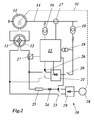
- Fig. 2 shows a schematic diagram of a dynamoelectric machine with brushless exciter according to a preferred embodiment of the invention.
- the configuration of the dynamoelectric machine 30 of Fig. 2 is - with the exception of the auxiliary DC current source - quite similar to the one of Fig. 1 : It comprises a generator 11 the output of which is connected to a bus bar 14, which leads to a grid not shown.
- the field winding of the generator 11 is fed by a brushless exciter 12, which generates an AC voltage, which is rectified by means of an internal rectifier 13.
- the field winding of the exciter 12 is supplied with a DC current.
- this DC current is generated from the bus bar voltage via an excitation transformer 18 and a subsequent thyristor-controlled rectifier bridge 21.
- An automatic voltage regulator (AVR) 15 monitors the voltage and current on the bus bar 14 via a voltage transducer 16 and a current transducer 17, and the DC current through the exciter field winding by means of a current transducer 27, and regulates the bus bar voltage according to predetermined regulation principles.
- the automatic voltage regulator 15 is energized from the bus bar 14 via excitation transformer 18 and a separate transformer 19.
- the rectifier bridge 21 is connectable at its input side to the excitation transformer 18 by means of a switch 20, and at its output side to the exciter field winding by means of a switch 26.
- an auxiliary DC current source 28, 29 can be used as an excitation DC current source by opening switch 26 and closing a switch 23, which connects the auxiliary DC current source 28, 29 to the exciter field winding via a diode 24 and a resistor 25.
- the auxiliary DC current source 28, 29 comprises a permanent magnet generator (PMG) 28, which is driven by the generator 11 via a mechanical link 31, and a subsequent rectifier bridge 29, which rectifies the AC voltage of the PMG thereby using simple diodes.
- PMG permanent magnet generator
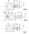
- the PMG can be fitted either on the turbine coupling to the generator, or the exciter coupling to the generator, or into the inside of the exciter.
- Fig. 3 shows schematically the second of the three alternatives mentioned above:
- the generator 11 is coupled along an axis 33 to the exciter 12 by means of an exciter coupling 32.
- the permanent magnet generator 28 is fitted to the exciter coupling 32.
- FIG. 4 shows schematically the first of the three alternatives mentioned above:
- a turbine (gas turbine, steam turbine) 34 is coupled along the axis 33 to the generator 11 by means of a turbine coupling 35.
- the permanent magnet generator 28 is fitted to the turbine coupling 32.
- Fig. 5 shows schematically the third of the three alternatives mentioned above:
- the permanent magnet generator 28 is fitted into the inside of the exciter 12.
- the exciter field winding is fed with a (regulated) DC current from the main DC current source 18, 21.
- the main DC current source 18, 21 is temporarily replaced by the auxiliary DC current source 28, 29 with its permanent magnet generator PMG. This replacement is done by opening the closed first switch 26 and closing the open second switch 23.
- the predetermined voltage level is preferably about 0.7U n , where U n is the nominal voltage on the grid.
Landscapes
- Engineering & Computer Science (AREA)
- Power Engineering (AREA)
- Control Of Eletrric Generators (AREA)
Abstract
A dynamoelectric machine (30) comprises a generator (11) with a generator field winding, the generator (11) being connected with its output to a bus bar (14), a brushless exciter (12) which feeds the generator field winding, the exciter (12) comprising an exciter field winding, which can be fed with a DC current from a main DC current source (18, 21) comprising an excitation transformer (18) connected to the bus bar (14) and a subsequent rectifier bridge (21), and an auxiliary DC current source (28, 29), which can be connected to the exciter field winding instead of the main DC current source (18, 21):
The system is improved by the auxiliary DC current source (28, 29) comprising a permanent magnet generator (28), which is mechanically linked to the generator (11), and subsequent rectifying means (29).
Description
- The present invention is about dynamoelectric machines. It relates to a dynamoelectric machine with a brushless exciter according to the preamble of claim 1 and a method for operating such a machine.
- Brushless excitation to feed the generator field winding is in widespread use. Brushless excitation is characterised by:
- No maintenance during operation.
- No pollution in the machine.
- Possibility to have ceiling voltage at reduced voltage on the grid or bus bar.
- Furthermore, an exciter with its static part being inside the rotating part is characterised by its compactness and a shorter machine hall (see for example the brochure "Alternateur d'excitation a diodes tournantes TKJ" Alsthom atlantique electromécanique, Belfort).
- The excitation system consists of a thyristor-controlled rectifier bridge and an excitation transformer. In some applications it is possible to have a permanent magnet generator (PMG) instead of the excitation transformer (see Fig. 19 in: Thanh Tam Tran, "L'excitation compacte, une evolution continue", Alsthom).
- Grid disturbances are often initiated by short-circuits in the transmission lines, even close to the power plant. Since the exciter transformer is fed by the generator bus bar, it also sees a lower voltage due to the short-circuit.
- Some grid code requires, that the generator unit shall be designed so that it remains connected to the grid and continues its stable operation after isolation of a line side fault within 0.25 seconds. This requires having the generator to be in an overexcited mode for low voltage (see
US-A-3,818,317 ). - On standard excitation, the excitation system can deliver the ceiling voltage, i.e. the maximum exciter voltage, up to about 0.7Un, where Un is the nominal grid voltage. If the voltage is less than 0.7Un, it is impossible to reach the ceiling voltage. On some generators, it is possible to generally replace the exciter transformer by a permanent magnet generator (PMG) to be able to deliver the ceiling voltage even for a voltage less than 0.7Un. However, on large 4 poles generators it is not possible, for mechanical reasons, to shrink a PMG on the shaft.
- The present solution is to get the ceiling voltage from a battery.
Fig. 1 shows the simplified circuit of this solution: Thedynamoelectric machine 10 ofFig. 1 comprises agenerator 11 the output of which is connected to abus bar 14, which leads to a grid not shown. The field winding of thegenerator 11 is fed by abrushless exciter 12, which generates an AC voltage, which is rectified by means of aninternal rectifier 13. The field winding of theexciter 12 is supplied with a DC current. During normal operation, this DC current is generated from the bus bar voltage via anexcitation transformer 18 and a subsequent thyristor-controlledrectifier bridge 21. An automatic voltage regulator (AVR) 15 monitors the voltage and current on thebus bar 14 via avoltage transducer 16 and acurrent transducer 17, and the DC current through the exciter field winding by means of acurrent transducer 27, and regulates the bus bar voltage according to predetermined regulation principles. Theautomatic voltage regulator 15 is energized from thebus bar 14 viaexcitation transformer 18 and aseparate transformer 19. - The
rectifier bridge 21 is connectable at its input side to theexcitation transformer 18 by means of aswitch 20, and at its output side to the exciter field winding by means of aswitch 26. When the ceiling voltage is needed in case of a voltage drop on thebus bar 14,battery 22 can be used as an excitation DC current source byopening switch 26 and closing aswitch 23, which connects thebattery 22 to the exciter field winding via adiode 24 and aresistor 25. - This solution is not completely acceptable because the voltage from the
battery 22 is limited to 220V. It means a voltage of only about 200 V on the exciter field winding, while the ceiling voltage on these generators can be above 220 V. - Other prior art solutions use a charged capacitor to provide the additional exciter current necessary in case of a voltage drop on the grid (
US-B1-6,339,316 ). - Furthermore, other solutions have been proposed, which use a permanent combination of a first DC current source and a second DC current source of the permanent magnet generator type. The
US-A-3,863,137 discloses an exciting system for a brushless alternator, in which a field coil of an exciter has a double winding structure, and DC power is supplied to one of the field coil windings from a permanent magnet generator, while DC power proportional to the output voltage of the alternator is supplied to the other field coil winding through a current converter. This arrangement is advantageous in that energizing power can be continuously supplied even in the case of a short-circuit of the alternator terminal and the output voltage subject to momentary fluctuations can be substantially immediately recovered. However, as the permanent magnet generator is continuously operating, it cannot be made small enough to fit into the exciter. - The same is true for a solution according to the
US-A-4,032,835 , where the base excitation is provided by a pilot exciter, and forcing excitation and fast de-excitation is provided by a supplemental power source. In practice, the supplemental power source may be a transformer connected to the main synchronous generator output terminals, a motor generator set, or by batteries through an inverter. The pilot exciter includes a permanent magnet field member mechanically connected to the shaft for rotation by the prime mover. - It is therefore an objective of the invention, to provide a dynamoelectric machine with a brushless exciter and a method for its operation, which avoid the disadvantages of the known solutions, provide an improved response to voltage fluctuations and short-circuits on the grid, and can be easily integrated into exciter arrangements of the "TKJ"-type, wherein the static part is concentrically surrounded by the rotating part.
- This objective is achieved by a dynamoelectric machine according to claim1 and a method according to claim 9.
- According to the invention, the exciter comprises an exciter field winding, which can be fed with a DC current from a main DC current source comprising an excitation transformer connected to the bus bar and a subsequent rectifier bridge; and alternatively with a DC current from an auxiliary DC current source, which can be connected to the exciter field winding instead of the main DC current source, whereby the auxiliary DC current source comprises a permanent magnet generator, which is mechanically linked to the generator, and subsequent rectifying means.
- According to one embodiment of the invention, the rectifying means comprise a rectifier bridge, which is a simple diode bridge.
- According to another embodiment of the invention, the permanent magnet generator is arranged inside the exciter.
- Still another embodiment of the invention is characterized in that the generator and the exciter are mechanically coupled by means of an exciter coupling; and the permanent magnet generator is arranged on the exciter coupling.
- According to a further embodiment of the invention the generator is mechanically coupled to a turbine by means of a turbine coupling; and the permanent magnet generator is arranged on the turbine coupling.
- Still another embodiment of the invention is characterized in that the main DC current source is connected to the exciter field winding by means of a first switch; and the auxiliary DC current source is connected to the exciter field winding by means of a second switch.
- In a further embodiment of the invention the dynamoelectric machine comprises an automatic voltage regulator, which controls the main DC current source in respect to the actual voltage and current on the bus bar; and the first and second switches are controlled by the automatic voltage regulator.
- The inventive method for operating the dynamoelectric machine comprises the steps of feeding the exciter field winding with a DC current from the main DC current source, when the voltage on the bus bar is above a predetermined voltage level; and replacing the main DC current source temporarily by the auxiliary DC current source, when the voltage on the bus bar falls below the predetermined voltage level.
- A first embodiment of the method according to the invention is characterized in that the main DC current source is connected to the exciter field winding by means of a first switch; the auxiliary DC current source is connected to the exciter field winding by means of a second switch; and the temporary replacement of the main DC current source by the auxiliary DC current source is done by opening the closed first switch and closing the open second switch.
- According to another embodiment the predetermined voltage level is about 0.7Un, where Un is the nominal voltage on the grid.
- The subject matter of the invention will be explained in more detail in the following text with reference to preferred exemplary embodiments, which are illustrated in the attached drawings, in which:
- Fig. 1
- a schematic diagram of a dynamoelectric machine with brushless exciter according to the prior art;
- Fig. 2
- in a diagram similar to
Fig. 1 a dynamoelectric machine according to a preferred embodiment of the invention; and - Fig. 3-5
- arrangements of the permanent magnet generator at the dynamoelectric machine in accordance with different embodiments of the invention.
- The invention starts from a dynamoelectric machine with a brushless exciter configuration of the "TKJ"-type, wherein the static part of the exciter is concentrically surrounded by the rotating part of the exciter. As there is not enough place to install a permanent magnet generator PMG to supply the excitation power during rated conditions, the idea is to have a PMG able to supply only the excitation power during the ceiling conditions (which last for a time period of about 5 s). In this case, the outline of the PMG can be made very small. Such a permanent magnet generator may be called "Impulse PMG", because it will be on load only a few seconds a year.
- The PMG shall be associated with its own exciter bridge, because the frequency of the voltage generated will be quite high in comparison with the grid frequency. The exciter bridge can therefore be a very simplified bridge with diodes as rectifying elements, as it is not necessary to have a regulator.
-
Fig. 2 shows a schematic diagram of a dynamoelectric machine with brushless exciter according to a preferred embodiment of the invention. The configuration of thedynamoelectric machine 30 ofFig. 2 is - with the exception of the auxiliary DC current source - quite similar to the one ofFig. 1 : It comprises agenerator 11 the output of which is connected to abus bar 14, which leads to a grid not shown. The field winding of thegenerator 11 is fed by abrushless exciter 12, which generates an AC voltage, which is rectified by means of aninternal rectifier 13. The field winding of theexciter 12 is supplied with a DC current. During normal operation, this DC current is generated from the bus bar voltage via anexcitation transformer 18 and a subsequent thyristor-controlledrectifier bridge 21. An automatic voltage regulator (AVR) 15 monitors the voltage and current on thebus bar 14 via avoltage transducer 16 and acurrent transducer 17, and the DC current through the exciter field winding by means of acurrent transducer 27, and regulates the bus bar voltage according to predetermined regulation principles. Theautomatic voltage regulator 15 is energized from thebus bar 14 viaexcitation transformer 18 and aseparate transformer 19. - The
rectifier bridge 21 is connectable at its input side to theexcitation transformer 18 by means of aswitch 20, and at its output side to the exciter field winding by means of aswitch 26. When the ceiling voltage is needed in case of a voltage drop on the grid orbus bar 14, respectively, an auxiliary DCcurrent source switch 26 and closing aswitch 23, which connects the auxiliary DCcurrent source diode 24 and aresistor 25. - The auxiliary DC
current source generator 11 via amechanical link 31, and asubsequent rectifier bridge 29, which rectifies the AC voltage of the PMG thereby using simple diodes. As the PMG is used only for a few seconds during the year, it can be made quite small. Accordingly, the PMG can be fitted either on the turbine coupling to the generator, or the exciter coupling to the generator, or into the inside of the exciter. -
Fig. 3 shows schematically the second of the three alternatives mentioned above: Thegenerator 11 is coupled along anaxis 33 to theexciter 12 by means of anexciter coupling 32. Thepermanent magnet generator 28 is fitted to theexciter coupling 32. -
Fig. 4 shows schematically the first of the three alternatives mentioned above: A turbine (gas turbine, steam turbine) 34 is coupled along theaxis 33 to thegenerator 11 by means of aturbine coupling 35. Thepermanent magnet generator 28 is fitted to theturbine coupling 32. -
Fig. 5 shows schematically the third of the three alternatives mentioned above: Thepermanent magnet generator 28 is fitted into the inside of theexciter 12. - During normal operation, i.e., when the voltage on the
bus bar 14 or grid is above a predetermined voltage level, the exciter field winding is fed with a (regulated) DC current from the main DCcurrent source bus bar 14 falls below the predetermined voltage level, the main DCcurrent source current source first switch 26 and closing the opensecond switch 23. The predetermined voltage level is preferably about 0.7Un, where Un is the nominal voltage on the grid. - The machine and operating method according to the invention has the following characteristics and advantages:
- The permanent magnet generator PMG supplies the exciter field only in case of a certain voltage drop on the grid.
- There is only one exciter field, controlled by the AVR; in case of the voltage drop the exciter field winding supply with DC current is switched over to the PMG.
- Since the PMG is activated (boosts) only temporarily, it can be kept quite small, such that it fits into the exciter bore of an exciter of the "TKG"-type.
-
- 10,30
- dynamoelectric machine
- 11
- generator
- 12
- exciter
- 13,29
- rectifier
- 14
- bus bar
- 15
- automatic voltage regulator (AVR)
- 16
- voltage transducer
- 17,27
- current transducer
- 18
- excitation transformer
- 19
- transformer
- 20,23,26
- switch
- 21
- rectifier bridge (thyristor-controlled)
- 22
- battery
- 24
- diode
- 25
- resistor
- 28
- permanent magnet generator (PMG)
- 29
- rectifier bridge
- 31
- mechanical link
- 32
- exciter coupling
- 33
- axis
- 34
- turbine
- 35
- turbine coupling
Claims (11)
- Dynamoelectric machine (30), comprisinga generator (11) with a generator field winding, the generator (11) being connected with its output to a bus bar (14);a brushless exciter (12) which feeds the generator field winding, the exciter (12) comprising an exciter field winding, which can be fed with a DC current from a main DC current source (18, 21) comprising an excitation transformer (18) connected to the bus bar (14) and a subsequent rectifier bridge (21); andan auxiliary DC current source (28, 29), which can be connected to the exciter field winding instead of the main DC current source (18, 21);characterized in thatthe auxiliary DC current source (28, 29) comprises a permanent magnet generator (28), which is mechanically linked to the generator (11), and subsequent rectifying means (29).
- Dynamoelectric machine as claimed in claim 1, characterized in that the rectifying means comprise a rectifier bridge (29).
- Dynamoelectric machine as claimed in claim 2, characterized in that the rectifier bridge (29) is a simple diode bridge.
- Dynamoelectric machine as claimed in one of the claims 1 to 3, characterized in that the permanent magnet generator (28) is arranged inside the exciter (12).
- Dynamoelectric machine as claimed in one of the claims 1 to 3,
characterized in thatthe generator (11) and the exciter (12) are mechanically coupled by means of an exciter coupling (32); andthe permanent magnet generator (28) is arranged on the exciter coupling (32). - Dynamoelectric machine as claimed in one of the claims 1 to 3,
characterized in thatthe generator (11) is mechanically coupled to a turbine (34) by means of a turbine coupling (35); andthe permanent magnet generator (28) is arranged on the turbine coupling (35). - Dynamoelectric machine as claimed in one of the claims 1 to 6,
characterized in thatthe main DC current source (18, 21) is connected to the exciter field winding by means of a first switch (26); andthe auxiliary DC current source (28, 29) is connected to the exciter field winding by means of a second switch (23). - Dynamoelectric machine as claimed in claim 7, characterized in thatthe dynamoelectric machine (30) comprises an automatic voltage regulator (15), which controls the main DC current source (18, 21) in respect to the actual voltage and current on the bus bar (14); andthe first and second switches (23, 26) are controlled by the automatic voltage regulator (15).
- Method for operating a dynamoelectric machine according to one of the claims 1 to 8, comprising the steps offeeding the exciter field winding with a DC current from the main DC current source (18, 21), when the voltage on the bus bar (14) is above a predetermined voltage level; andreplace the main DC current source (18, 21) temporarily by the auxiliary DC current source (28, 29), when the voltage on the bus bar (14) falls below the predetermined voltage level.
- Method according to claim 9, characterized in thatthe main DC current source (18, 21) is connected to the exciter field winding by means of a first switch (26);the auxiliary DC current source (28, 29) is connected to the exciter field winding by means of a second switch (23); andthe temporary replacement of the main DC current source (18, 21) by the auxiliary DC current source (28, 29) is done by opening the closed first switch (26) and closing the open second switch (23).
- Method according to claim 9 or 10, characterized in that the predetermined voltage level is about 0.7Un, where Un is the nominal voltage on the grid.
Priority Applications (1)
| Application Number | Priority Date | Filing Date | Title |
|---|---|---|---|
| EP07102468A EP1959555A1 (en) | 2007-02-15 | 2007-02-15 | Dynamoelectric machine with a brushless exciter and method for operating such a dynamoelectric machine |
Applications Claiming Priority (1)
| Application Number | Priority Date | Filing Date | Title |
|---|---|---|---|
| EP07102468A EP1959555A1 (en) | 2007-02-15 | 2007-02-15 | Dynamoelectric machine with a brushless exciter and method for operating such a dynamoelectric machine |
Publications (1)
| Publication Number | Publication Date |
|---|---|
| EP1959555A1 true EP1959555A1 (en) | 2008-08-20 |
Family
ID=38292639
Family Applications (1)
| Application Number | Title | Priority Date | Filing Date |
|---|---|---|---|
| EP07102468A Withdrawn EP1959555A1 (en) | 2007-02-15 | 2007-02-15 | Dynamoelectric machine with a brushless exciter and method for operating such a dynamoelectric machine |
Country Status (1)
| Country | Link |
|---|---|
| EP (1) | EP1959555A1 (en) |
Cited By (6)
| Publication number | Priority date | Publication date | Assignee | Title |
|---|---|---|---|---|
| RU2470454C2 (en) * | 2010-12-02 | 2012-12-20 | Федеральное государственное образовательное учреждение высшего профессионального образования "Волжская государственная академия водного транспорта" (ФГОУ ВПО ВГАВТ) | System of excitation of synchronous generator |
| RU2510698C1 (en) * | 2012-11-28 | 2014-04-10 | Федеральное бюджетное образовательное учреждение высшего профессионального образования "Волжская государственная академия водного транспорта" (ФБОУ ВПО ВГАВТ) | System of synchronous generator excitation with external boosting |
| WO2014064337A3 (en) * | 2012-10-24 | 2014-10-09 | Wärtsilä Finland Oy | Dynamo-electric machine |
| WO2015138554A1 (en) * | 2014-03-12 | 2015-09-17 | General Electric Company | Brushless permanent magnet generator plus auxiliary voltage source constant potential exciter |
| RU2569402C2 (en) * | 2013-03-29 | 2015-11-27 | Альстом Текнолоджи Лтд | Control system of steam turbine for maintenance of synchronisation and method for its implementation |
| JP2019140783A (en) * | 2018-02-09 | 2019-08-22 | 株式会社東芝 | Brushless synchronous generator |
Citations (5)
| Publication number | Priority date | Publication date | Assignee | Title |
|---|---|---|---|---|
| US3758843A (en) * | 1971-08-14 | 1973-09-11 | Meidensha Electric Mfg Co Ltd | Brushless excitation device |
| US3863137A (en) * | 1972-08-23 | 1975-01-28 | Hitachi Ltd | Exciting system for alternator |
| US4015189A (en) * | 1976-03-15 | 1977-03-29 | Westinghouse Electric Corporation | Supplemental field excitation for permanent magnet rotor of pilot exciter |
| US4032835A (en) * | 1976-03-15 | 1977-06-28 | Westinghouse Electric Corporation | Brushless exciter supplemental ceiling excitation system |
| US4336486A (en) * | 1980-01-09 | 1982-06-22 | Westinghouse Electric Corp. | Dynamoelectric machines brushless supplemental excitation system |
-
2007
- 2007-02-15 EP EP07102468A patent/EP1959555A1/en not_active Withdrawn
Patent Citations (5)
| Publication number | Priority date | Publication date | Assignee | Title |
|---|---|---|---|---|
| US3758843A (en) * | 1971-08-14 | 1973-09-11 | Meidensha Electric Mfg Co Ltd | Brushless excitation device |
| US3863137A (en) * | 1972-08-23 | 1975-01-28 | Hitachi Ltd | Exciting system for alternator |
| US4015189A (en) * | 1976-03-15 | 1977-03-29 | Westinghouse Electric Corporation | Supplemental field excitation for permanent magnet rotor of pilot exciter |
| US4032835A (en) * | 1976-03-15 | 1977-06-28 | Westinghouse Electric Corporation | Brushless exciter supplemental ceiling excitation system |
| US4336486A (en) * | 1980-01-09 | 1982-06-22 | Westinghouse Electric Corp. | Dynamoelectric machines brushless supplemental excitation system |
Cited By (10)
| Publication number | Priority date | Publication date | Assignee | Title |
|---|---|---|---|---|
| RU2470454C2 (en) * | 2010-12-02 | 2012-12-20 | Федеральное государственное образовательное учреждение высшего профессионального образования "Волжская государственная академия водного транспорта" (ФГОУ ВПО ВГАВТ) | System of excitation of synchronous generator |
| WO2014064337A3 (en) * | 2012-10-24 | 2014-10-09 | Wärtsilä Finland Oy | Dynamo-electric machine |
| RU2510698C1 (en) * | 2012-11-28 | 2014-04-10 | Федеральное бюджетное образовательное учреждение высшего профессионального образования "Волжская государственная академия водного транспорта" (ФБОУ ВПО ВГАВТ) | System of synchronous generator excitation with external boosting |
| RU2569402C2 (en) * | 2013-03-29 | 2015-11-27 | Альстом Текнолоджи Лтд | Control system of steam turbine for maintenance of synchronisation and method for its implementation |
| US9309779B2 (en) | 2013-03-29 | 2016-04-12 | Alstom Technology Ltd | Steam turbine governing system for maintaining synchronization and process for performing the same |
| WO2015138554A1 (en) * | 2014-03-12 | 2015-09-17 | General Electric Company | Brushless permanent magnet generator plus auxiliary voltage source constant potential exciter |
| US9252695B2 (en) | 2014-03-12 | 2016-02-02 | General Electric Company | Brushless permanent magnet generator plus auxiliary voltage source constant potential exciter |
| CN106063118A (en) * | 2014-03-12 | 2016-10-26 | 通用电气公司 | Brushless permanent magnet generator plus auxiliary voltage source constant potential exciter |
| JP2017512451A (en) * | 2014-03-12 | 2017-05-18 | ゼネラル・エレクトリック・カンパニイ | Brushless permanent magnet generator and auxiliary voltage source constant potential exciter |
| JP2019140783A (en) * | 2018-02-09 | 2019-08-22 | 株式会社東芝 | Brushless synchronous generator |
Similar Documents
| Publication | Publication Date | Title |
|---|---|---|
| EP0237246B1 (en) | Starter generator system | |
| EP2109932B1 (en) | Method of and apparatus for controlling excitation | |
| US6169390B1 (en) | Flywheel-microturbine system | |
| JP3860333B2 (en) | System for stabilization of power supply system | |
| US6844707B1 (en) | AC/DC brushless starter-generator | |
| US8970183B2 (en) | Overvoltage limiter in an aircraft electrical power generation system | |
| US5097195A (en) | AC exciter for VSCF starter/generator | |
| US6768278B2 (en) | Gas turbine engine starter generator with switchable exciter stator windings | |
| US20050046398A1 (en) | Control apparatus for a starter/generator system | |
| EP2259422A1 (en) | Starting/generating system with multi-functional circuit breaker | |
| EP1959555A1 (en) | Dynamoelectric machine with a brushless exciter and method for operating such a dynamoelectric machine | |
| US20100141028A1 (en) | More electric engine with regulated permanent magnet machines | |
| EP2139099A2 (en) | Regulated hybrid permanent magnet generator | |
| EP0154626A1 (en) | UNINTERRUPTIBLE POWER SUPPLY. | |
| US5283471A (en) | DC generator and back-up engine starting apparatus | |
| EP2045910B1 (en) | Starter/generator system with control to address a voltage rise | |
| US20100321968A1 (en) | Load fault handling for switched reluctance or induction type machines | |
| CN106471730B (en) | It is powered with exciting current to synchronous motor | |
| EP1381149B1 (en) | Starting of switched reluctance generators | |
| EP2912765B1 (en) | Dynamo-electric machine | |
| EP4675878A1 (en) | Rotating stabilisers | |
| KR200309454Y1 (en) | Excitation System by Using Auxiliary Winding for Marine Generator | |
| CA3189412A1 (en) | Uninterruptible power supply system with engine start-up | |
| HK1133959B (en) | Method of and apparatus for controlling excitation | |
| JPH09322502A (en) | Brushless self-excitation generator |
Legal Events
| Date | Code | Title | Description |
|---|---|---|---|
| PUAI | Public reference made under article 153(3) epc to a published international application that has entered the european phase |
Free format text: ORIGINAL CODE: 0009012 |
|
| AK | Designated contracting states |
Kind code of ref document: A1 Designated state(s): AT BE BG CH CY CZ DE DK EE ES FI FR GB GR HU IE IS IT LI LT LU LV MC NL PL PT RO SE SI SK TR |
|
| AX | Request for extension of the european patent |
Extension state: AL BA HR MK RS |
|
| AKX | Designation fees paid | ||
| REG | Reference to a national code |
Ref country code: DE Ref legal event code: 8566 |
|
| STAA | Information on the status of an ep patent application or granted ep patent |
Free format text: STATUS: THE APPLICATION IS DEEMED TO BE WITHDRAWN |
|
| 18D | Application deemed to be withdrawn |
Effective date: 20090221 |