EP1959511A1 - A thread driven polyhedron ultrasonic motor - Google Patents
A thread driven polyhedron ultrasonic motor Download PDFInfo
- Publication number
- EP1959511A1 EP1959511A1 EP06817834A EP06817834A EP1959511A1 EP 1959511 A1 EP1959511 A1 EP 1959511A1 EP 06817834 A EP06817834 A EP 06817834A EP 06817834 A EP06817834 A EP 06817834A EP 1959511 A1 EP1959511 A1 EP 1959511A1
- Authority
- EP
- European Patent Office
- Prior art keywords
- stator
- rotor
- screw threads
- ultrasonic motor
- tube
- Prior art date
- Legal status (The legal status is an assumption and is not a legal conclusion. Google has not performed a legal analysis and makes no representation as to the accuracy of the status listed.)
- Granted
Links
- 239000000919 ceramic Substances 0.000 claims description 41
- 230000009977 dual effect Effects 0.000 claims description 23
- 230000005291 magnetic effect Effects 0.000 claims description 21
- 238000005452 bending Methods 0.000 claims description 8
- 238000002955 isolation Methods 0.000 claims description 6
- 238000005299 abrasion Methods 0.000 claims description 5
- 239000000463 material Substances 0.000 claims description 3
- 239000007787 solid Substances 0.000 claims description 2
- 230000003287 optical effect Effects 0.000 description 17
- 230000005540 biological transmission Effects 0.000 description 9
- 238000010586 diagram Methods 0.000 description 9
- 230000033001 locomotion Effects 0.000 description 8
- 230000007246 mechanism Effects 0.000 description 7
- 230000005284 excitation Effects 0.000 description 5
- 230000005294 ferromagnetic effect Effects 0.000 description 5
- 238000000034 method Methods 0.000 description 5
- 239000000306 component Substances 0.000 description 2
- 239000008358 core component Substances 0.000 description 2
- 230000000694 effects Effects 0.000 description 2
- 239000002184 metal Substances 0.000 description 2
- 229910000831 Steel Inorganic materials 0.000 description 1
- 150000001875 compounds Chemical class 0.000 description 1
- 230000006835 compression Effects 0.000 description 1
- 238000007906 compression Methods 0.000 description 1
- 238000003384 imaging method Methods 0.000 description 1
- 239000007769 metal material Substances 0.000 description 1
- ORQBXQOJMQIAOY-UHFFFAOYSA-N nobelium Chemical compound [No] ORQBXQOJMQIAOY-UHFFFAOYSA-N 0.000 description 1
- 229910052755 nonmetal Inorganic materials 0.000 description 1
- 230000000979 retarding effect Effects 0.000 description 1
- 239000010959 steel Substances 0.000 description 1
Images


Classifications
-
- H—ELECTRICITY
- H02—GENERATION; CONVERSION OR DISTRIBUTION OF ELECTRIC POWER
- H02N—ELECTRIC MACHINES NOT OTHERWISE PROVIDED FOR
- H02N2/00—Electric machines in general using piezoelectric effect, electrostriction or magnetostriction
-
- H—ELECTRICITY
- H02—GENERATION; CONVERSION OR DISTRIBUTION OF ELECTRIC POWER
- H02N—ELECTRIC MACHINES NOT OTHERWISE PROVIDED FOR
- H02N2/00—Electric machines in general using piezoelectric effect, electrostriction or magnetostriction
- H02N2/02—Electric machines in general using piezoelectric effect, electrostriction or magnetostriction producing linear motion, e.g. actuators; Linear positioners ; Linear motors
-
- H—ELECTRICITY
- H02—GENERATION; CONVERSION OR DISTRIBUTION OF ELECTRIC POWER
- H02N—ELECTRIC MACHINES NOT OTHERWISE PROVIDED FOR
- H02N2/00—Electric machines in general using piezoelectric effect, electrostriction or magnetostriction
- H02N2/0095—Electric machines in general using piezoelectric effect, electrostriction or magnetostriction producing combined linear and rotary motion, e.g. multi-direction positioners
-
- H—ELECTRICITY
- H02—GENERATION; CONVERSION OR DISTRIBUTION OF ELECTRIC POWER
- H02N—ELECTRIC MACHINES NOT OTHERWISE PROVIDED FOR
- H02N2/00—Electric machines in general using piezoelectric effect, electrostriction or magnetostriction
- H02N2/10—Electric machines in general using piezoelectric effect, electrostriction or magnetostriction producing rotary motion, e.g. rotary motors
- H02N2/16—Electric machines in general using piezoelectric effect, electrostriction or magnetostriction producing rotary motion, e.g. rotary motors using travelling waves, i.e. Rayleigh surface waves
- H02N2/163—Motors with ring stator
Definitions
- the present invention relates to the field of ultrasonic application, and more particularly to a configuration design for a screw thread driving system of a polyhedral tube-shaped ultrasonic motor.
- Fig. 1 is a schematic diagram of configuration of a polyhedral tube ultrasonic motor, wherein Fig. 1 (1) shows the configuration of its main part, which includes a vibrator comprising a stator 13 and electrostriction elements (piezoelectric ceramic plates) 11, 12 bonded to surfaces of the stator 13. They can be multiple electrodes divided from a piezoelectric tube, or they can also be formed by bonding the multiple piezoelectric plates to the external surface of the piezoelectric tube (the polyhedral tube is made of metal materials or surfaces contacted with the piezoelectric plates are metal electric conductive layers). The internal surface of the vibrator is a smooth torus.
- the rotor uses a tube of a ring 15 with an opening 14.
- Fig. 2 (1) and Fig. 2 (2) are schematic diagrams of the configuration of an ultrasonic motor with conical axis output of a polyhedral tube, wherein the internal surface of a stator 21 has conical teeth 22, and a vibrator is formed by bonding piezoelectric ceramic plates23 to the external surfaces of the stator21, the conical body contacted with the conical teeth 22 is used as a rotor 24.
- Fig2 (3) is an assembly drawing of the configuration applied to a robot joint, where the vibrator is covered by a motor hood 27, front cover 25 and back cover 26 are provided via cushion 29 on its both ends, and both the front cover and back cover are connected with the motor hood 27 as a whole by fastening bolts 28. Such configuration directly transfers the vibration of the vibrator to the rotor.
- the screw threads driving polyhedral ultrasonic motor comprises a stator, a rotor and multiple piezoelectric ceramic plates bonded to the stator or the rotor as a whole, characterized in that, said stator has screw threads on the surface in contact with the rotor, and said rotor also has screw threads matching with those on the stator.
- the present invention has simple configuration; the stator and the rotor directly contact each other via the screw threads.
- the stator drives the rotor via the screw threads and no other transmission mechanism is needed, so it is more suitable for micromation, and has a promising prospect in broad fields such as micro-machine and optical focusing and zooming.
Abstract
Description
- The present invention relates to the field of ultrasonic application, and more particularly to a configuration design for a screw thread driving system of a polyhedral tube-shaped ultrasonic motor.
- A piezoelectric ultrasonic motor is a driving mechanism utilizing converse piezoelectric effect of piezoelectric materials and made of a specific configuration, and it generally comprises functional components such as piezoelectric ceramic, stators, rotors, pre-pressure mechanism and transmission mechanism. It utilizes converse piezoelectric effect of piezoelectric ceramic so as to generate ultrasonic vibration on surfaces of the stators and drive the rotors via force of friction between the stators and the rotors. The ultrasonic motor has following advantages over ordinary electromagnetic motors:
- 1. Low rotating speed, high torque, and the load can be driven directly without retarding mechanisms.
- 2. Small volume, flexible configuration, and more particularly, the power to volume ratio is 3-10 times of the electromagnetic motors
- 3. Quick response to both start and stop, and more particularly, the response time is less than 1ms.
- 5. Having self-hold torque, no gear gap, and can be used for precision positioning.
- 6. Quiet operation, no noise.
-
Fig. 1 andFig. 2 show a piezoelectric ultrasonic motor in prior art. -
Fig. 1 is a schematic diagram of configuration of a polyhedral tube ultrasonic motor, whereinFig. 1 (1) shows the configuration of its main part, which includes a vibrator comprising astator 13 and electrostriction elements (piezoelectric ceramic plates) 11, 12 bonded to surfaces of thestator 13. They can be multiple electrodes divided from a piezoelectric tube, or they can also be formed by bonding the multiple piezoelectric plates to the external surface of the piezoelectric tube (the polyhedral tube is made of metal materials or surfaces contacted with the piezoelectric plates are metal electric conductive layers). The internal surface of the vibrator is a smooth torus. The rotor uses a tube of aring 15 with anopening 14. The rotor is installed on the internal surface of the vibrator, working under the driving principle of travelling wave ultrasonic motors, when a corresponding driving voltage is added on the piezoelectric ceramic plates, the travelling wave generated on the internal surface of the vibrator can rotate with respect to the ring. The opening on thering 15 is set for the purpose of increasing pre-pressure to the contact surface between the stator and the rotor. - The motor is intended to apply to a zoom system of lens.
Fig. 1 (2) shows the configuration of a screw thread transmission system of such application, where screw threads are carved on the front end of a drawtube 15 (corresponding to said rotor), which is immovable in the apparatus.Reference sign 13 refers to a polyhedral tube-shaped ring, whose external surface is bonded with piezoelectricceramic plates 11, 12 (corresponding to said vibrator). Afront bracket 16 is bonded to the front end of thepolyhedral tube 13 so as to be integrated with the piezoelectricceramic plates front bracket 16 is carved with screw threads which are coupled with those on the front end of thedrawtube 15. The group of zoom lens are installed on the front bracket via a fastening ring, and screw threads are formed at the rear end of the bracket which is coupled with the screw threads on the left end of thedrawtube 15. The vibrator is bonded to the end of the front bracket, and the internal surface of the vibrator is in contact with the external surface of the drawtube. When the piezoelectric ceramic are excited by an electric signal, thepiezoelectric plates polyhedron 13 are driven to rotate with respect to thedrawtube 15, and thefront bracket 16 are also brought to rotate. Thus a torus driving is generated on the external surface of the drawtube. The left end of the drawtube is carved with screw threads so that the front bracket can move linearly along the axial direction as a result of the relative rotation of the screw threads between the front bracket and the front end of the drawtube. Zooming and focusing can be realized via the rectilinear movement, so the system above is called a screw thread transmission system. The piezoelectric exciting signal is introduced into the system via a connection switch. -
Fig. 2 (1) andFig. 2 (2) are schematic diagrams of the configuration of an ultrasonic motor with conical axis output of a polyhedral tube, wherein the internal surface of astator 21 hasconical teeth 22, and a vibrator is formed by bonding piezoelectric ceramic plates23 to the external surfaces of the stator21, the conical body contacted with theconical teeth 22 is used as arotor 24.Fig2 (3) is an assembly drawing of the configuration applied to a robot joint, where the vibrator is covered by amotor hood 27,front cover 25 andback cover 26 are provided viacushion 29 on its both ends, and both the front cover and back cover are connected with themotor hood 27 as a whole by fasteningbolts 28. Such configuration directly transfers the vibration of the vibrator to the rotor. - The drawback of the configuration above is that the rotation is transformed into the rectilinear motion by other transmission mechanism (screw thread transmission or screw transmission) in actual practice.
- The purpose of the present invention is to provide a screw threads driving system of a polyhedral tube-shaped ultrasonic motor that overcomes the drawbacks in the prior art so that it can have simple configuration. The relative movement between a stator and a rotor can be generated directly via the contact of screw threads, and the rotation can be transformed into the rectilinear motion without other transmission mechanism, which can make the application configuration more simple and compact, and is more suitable for the micromation. And it has a promising prospect in broad fields such as micro-machine and optical focusing and zooming.
- The screw threads driving polyhedral ultrasonic motor provided by the present invention comprises a stator, a rotor and multiple piezoelectric ceramic plates bonded to the stator or the rotor as a whole, characterized in that, said stator has screw threads on the surface in contact with the rotor, and said rotor also has screw threads matching with those on the stator.
- Said stator can be held on either or both ends. The external screw threads or internal screw threads of the stator and corresponding rotor can be formed on the whole or part of the tube (upper, middle or lower part)
- Said piezoelectric ceramic plates can be bonded to the stator or the rotor so as to form the vibrator, the bonding surfaces between the piezoelectric ceramic plates and the stator or the rotor are polyhedral.
- Said stator can be configured surrounding the rotor or being surrounded by the rotor.
- The number of said piezoelectric ceramic plates is the multiple of 3 or 4; or 1, 2, 3 or any other integer which can generate in-plane bending travelling waves or standing waves with corresponding excitation.
- The present invention has simple configuration; the stator and the rotor directly contact each other via the screw threads. The stator drives the rotor via the screw threads and no other transmission mechanism is needed, so it is more suitable for micromation, and has a promising prospect in broad fields such as micro-machine and optical focusing and zooming.
-
-
Fig. 1 is a schematic diagram of the configuration of a prior polyhedral tube ultrasonic motor, whereinFig. 1 (1) shows the configuration of its core components, andFig. 1 (2) is a schematic diagram structure sketch drawing of a screw thread transmission system utilizing the configuration; -
Fig. 2 is a schematic diagram of a prior ultrasonic motor with conical axis output of polyhedral tube, whereinFig. 2 (1) andFig. 2 (2) show the configuration of its core components, andFig. 2 (3) is an assembly drawing of the configuration applied to the robot joint; -
Fig. 3 is a diagram illustrating of a polyhedral tube-shaped ultrasonic motor with screw threads driving system according to the embodiment 1of present invention; -
Fig. 4 is a diagram illustrating of a tetrahedron tube-shaped screw threads driving system with inner stator according to theembodiment 2 of present invention; -
Fig. 5 is a diagram illustrating of an octahedron tube-shaped screw threads driving system with outer stator according to the embodiment 3 of present invention; -
Fig. 6 is a cross-section view of the screw threads driving system of an ultrasonic motor with a pre-pressure spring according to the embodiment 4 of present invention; -
Fig. 7 is a cross-section view of the screw threads driving system of an ultrasonic motor with a rotor cap and a pre-pressure spring according to the embodiment 5 of present invention; -
Fig. 8 is a cross-section view of the screw threads driving system of a dual stator ultrasonic motor with a pre-pressure spring according to the embodiment 6 of present invention; -
Fig. 9 is a cross-section view of the screw threads driving system of a dual stator ultrasonic motor with a U-shaped pre-pressure elastic strip according to the embodiment 7 of present invention; -
Fig. 10 is a cross-section view of the screw threads driving system of a dual rotor ultrasonic motor with a pre-pressure spring according to the embodiment 8 of present invention;; -
Fig. 11 is a cross-section view of the screw threads driving system of a dual rotor ultrasonic motor with a U-shaped pre-pressure elastic strip according to the embodiment 9 of present invention; -
Fig. 12 is a cross-section view of the screw threads driving system of a dual rotor ultrasonic motor with a magnetic ring according to the embodiment 10 of present invention; and -
Fig. 13 is a schematic diagram of screw threads driving configuration of a standing wave ultrasonic motor excited by single piezoelectric plate according to theembodiment 11 of present invention. -
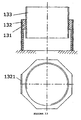
- Embodiment 1: is a screw thread driving dodecahedral tube ultrasonic motor, as shown in
Fig. 3 , which comprises 12 pieces of piezoelectricceramic plates 31 that are bonded to the external surfaces of adodecahedral tube 32 respectively to form a vibrator, the piezoelectricceramic plates dodecahedral tube 32 has screw threads on the internal surface thereof, around tube 33 is placed therein, and the external surface of the round tube has external screw threads, which are matched with the screw threads on thedodecahedral tube 32. One end of theround tube 33 is immovably supported as a stator and the vibrator is used as a rotor. If the piezoelectricceramic plates ceramic plates rotor 32 which will move relative to thestator 33, when the piezoelectricceramic plates ceramic plates - Embodiment 2: is a tetrahedral tube ultrasonic motor driven by screw thread, whose configuration is shown in
Fig. 4 . It comprises an inner tube shapedstator 41 comprising a convexity thereon. The convexity has external screw threads on the external surface thereof, the external surface of the lower part of the stator is tetrahedral, the piezoelectric ceramic plates 42 (totally 4 pieces: 421, 422, 423, 424) are bonded to the tetrahedron respectively so as to form a vibrator, thestator 41 is placed in an outer tube shapedrotor 43 having internal screw threads, and the internal screw threads on the rotor are matched with the external screw threads on the stator; a fixed tube 44 is placed inside the stator, the bottom of the tube 44 and the bottom of the stator are immovably supported together.
If all of the piezoelectric ceramic plates bonded to the stator are positive polarized, the bending travelling waves can be generated within thestator 41 and drive therotor 43 to rotate and move axially when the piezoelectricceramic plates
When the piezoelectricceramic plates ceramic plates ceramic plates ceramic plates - Embodiment 3: is an octahedral tube ultrasonic motor driven by screw threads, as shown in
Fig. 4 , comprising:
Aouter tube stator 51, which has a convexity on the upper part of internal surface , and internal screw threads are provided on the internal surface where the convexity is formed, the bottom of the stator is immovably supported; the external surface of the stator is octahedral, the piezoelectric ceramic plates 52 (including 8 pieces: 521, 522, 523, 524, 525, 526, 527, 528) are bonded to the octahedron respectively so as to form a vibrator, aninner tube rotor 53 with external screw threads is placed in thestator 51, and the external screw threads on the rotor are matched with the internal screw threads on the stator.
If all of the piezoelectric ceramic plates bonded to the stator are positive polarized, the bending travelling waves are generated on the upper part of thestator 51 and drive therotor 53 to rotate and move axially when the piezoelectricceramic plates
If the piezoelectricceramic plates ceramic plates rotor 53 can be driven to rotate and move axially by two signals, one is sinωt for the excitation of the piezoelectricceramic plates ceramic plates - Embodiment 4: a screw threads driving system of an ultrasonic motor with a pre-pressure spring.
The screw threads driving system of an ultrasonic motor with a pre-pressure spring of the present embodiment comprises an ultrasonic motor, a driven element embedded in the ultrasonic motor and a pre-pressure spring. As shown inFig. 6 , the ultrasonic motor comprises arotor 61 and astator piezoelectric elements 62 are bonded to the stator 63 (thepiezoelectric elements 62 can be formed in the shape of a sheet, a curve sheet, a cylinder, or various polyhedral, annular tube in whole or conical tube in whole). There are screw threads being matched with each other on both the stator and the rotor, the cross section of the screw threads are formed in the shape of triangle, trapezoid, rectangle, convexity or various shapes and their combinations, the screw threads can be continuous, intermittent or a curve having a particular locus. The surfaces of the screw threads are processed to be abrasion resistant or are coated with abrasion resistant materials. The driven element can be selectively set in acavity 69 of thestator 63 or/and acavity 67 of therotor 61. An isolation strip having athin wall 65 is set on one end of the stator, one end of the isolation strip is fixed on abase 64, and the isolation strip is used for reducing the influence of the base to the stator vibration. There is an interval between common screw threads contact pair. Furthermore, the return interval in reciprocate will affect the movement precision. Therefore, it is necessary to pre-tighten the screw threads pair. InFig. 6 , a compression spring is used to exert an axial pre-pressure between therotor 67 and thebase 64, the axial pre-pressure makes the screw threads always contact with each other in the same direction so as to eliminate the return interval, and the pre-pressure also provides a way to adjust driving force of friction. A bearing 66 with a steel ball is set on the base or the stator as well so as to reduce the friction force when the rotor rotates. The form of the spring can also be an elastic strip, and the form of the bearing can also be a groove holding a ball or can be a slider.
Theelement
When the alternating voltage is applied to thepiezoelectric element 62, thestator 63 directly drives therotor 61 to rotate via friction, and the rotation of therotor 61 is transformed into the relatively axial rectilinear motion thereof via the motion transfer of screw thread, so that the driven element set on the rotor can move linearly along the axial direction. When the optical lens (groups) is brought to move, it functions as optical focusing and zooming. - Embodiment 5: a screw threads driving system of an ultrasonic motor with a rotor cap and a pre-pressure spring.
As shown inFig. 7 , the main differences between the present embodiment and embodiment 4 are: in the present embodiment, apre-pressure spring 712 is positioned outside thestator 73, thespring 712 has two supporting ends, one of which is set on therotor cap 711, and the other is set on thebearing 74. The bearing 74 can be set on thebase 79, or can also be set on thestator 73 so as to reduce the return interval and the friction force when therotor 711 rotates. The form of the spring can also be an elastic strip, and the form of the bearing can also be a groove holding a ball or can be a slider.Reference sign 77 refers to an abrasion resistant coat.
Two rings both are magnetic or one is magnetic and the other is ferromagnetic can be provided at the interval between thestator 73 and therotor 711 so as to generate a magnetic attractive force to provide the pre-pressure. - Embodiment 6: a screw threads driving system of a dual stator ultrasonic motor with a pre-pressure spring.
As shown inFig. 8 , a double stator configuration with a pre-pressure spring has been adopted in present embodiment. Stators 82 and 86 drive arotor 810 to move simultaneously. One end of thestator 86 is fixed on abase 89 via anisolation strip 88, and aspring 83 is set between the two stators to provide a pre-pressure so as to press the screw threads of the stators and rotors with each other tightly.Blocks stators groove 813 to preventstator 82 from rotating. When an alternating voltage is applied to thepiezoelectric elements stators rotor 811 and/or the cavity of the stator such as 812 so as to bring the optical lens group to move and realize optical focusing and zooming.
The other parts are the same as or similar to those described in embodiment 4 or 5 both in configuration and the method of usage, therefore it is not necessary to describe in detail. - Embodiment 7: a screw threads driving system of a dual stator ultrasonic motor with a U-shaped pre-pressure elastic strip.
As shown inFig. 9 , the main differences between present embodiment and embodiment 6 are: in present embodiment, a U-shaped pre-pressureelastic strip 94 is used to connect with twostators stator 91 will not rotate, but a pre-pressure is provided between thestators
The other parts are the same as or similar to those described in embodiment 4 or 5 in both configurations and the method of usage, therefore it is not necessary to describe in detail. - Embodiment 8: a screw threads driving system of a dual rotor ultrasonic motor with a pre-pressure spring.
As shown inFig. 10 , a dual rotor configuration with a pre-pressure spring is adopted in present embodiment. Tworotors 103 and 105 are used in the present embodiment, where aspring 104 provides a pre-pressure between the tworotors 103 and 105 so as to press the screw threads of the stators and rotors with each other tightly. Two rotors are anchored via agroove 109 to prevent relative rotation, and astator 101drive rotors 103 and 105 to rotate simultaneously. One end or thestator 101 is fixed directly on abase 107; or the stator can also be fixed on a base via an isolation strip used in the embodiment 5. The driven elements set on the rotor can move linearly along the axial direction. If an optical lens group is installed in the cavity of therotor 1010 and/or the cavity of the stator such asstator 108, therotors 103 and 105 will rotate simultaneously so as to bring the optical lens group to move to realize optical zooming and focusing when the alternating voltage is applied to the piezoelectric element 102.
Alternatively, two rings both of which are magnetic or one is magnetic and the other is ferromagnetic can be positioned between the two rotors so as to generate a magnetic attractive force and provide a pre-pressure. - Embodiment 9: a screw threads driving system of a dual rotor ultrasonic motor with a U-shaped pre-pressure elastic strip
As shown inFig. 11 , the main differences between present embodiment and embodiment 8 are: in present embodiment, a U-shaped pre-pressureelastic strip 114 is used to connect with tworotors rotators
Alternatively, two rings both of which are magnetic or one is magnetic and the other is ferromagnetic can be adopted between the two rotors so as to generate a magnetic attractive force to provide a pre-pressure.
The other parts are the same as or similar to those described in embodiment 8 in both configuration and the method of usage, therefore it is not necessary to describe in detail. - Embodiment 10: a screw thread driving system of a dual rotor ultrasonic motor with magnetic rings.
As shown inFig. 12 , the main differences between present embodiment and embodiment 8 are: in present embodiment, twomagnetic rings 1212 are adopted to provide pre-pressure betweenrotators groove 129 is used to connect with tworotors magnetic rings 1212 can be replaced by a magnetic one and a ferromagnetic one. And themagnetic rings 1212 can also be set between a rotor and a base (or a stator) or between two (multiple) stators.
The other parts are the same as or similar to those described in embodiment 8 in both configuration and the method of usage, therefore it is not necessary to describe in detail. - Embodiment 11: as shown in
Fig. 13 , arotor 133 is solid, only one piezoelectric ceramic plate 1321 (two or three and multiple of two or three piezoelectric ceramic plate can be also used) is bonded to astator 131. A single-phase signal voltage excites the stator to generate an in-plane bending standing wave, the bending standing wave drives the rotor to rotate and move linearly via the friction caused by the contact of the screw threads between the stator and the rotor. The stator or the rotor can also be single, dual or multiple, and a pre-pressure can be exerted thereon as embodiments 4-10. The rotor can drive a micro-positioner or a micro-pump.
According to the embodiments above, by using a single rotor and a single stator or dual rotors or dual stators configuration, and by providing a pre-pressure via a spring, a U-shaped elastic strip or magnetic elements, the screw threads between the stator and the rotor can be pressed tightly to eliminate the return interval and to increase the driving force, so as to produce relative motion of the stator and the rotor along axial direction, and the driven component placed on the rotor can be brought to move rectilinearly along the axial direction. By moving the optical lens group, optical zooming and focusing is realized. And by changing the distance between the optical lens (group) and imaging element, simple or compound optical zooming and focusing can be realized.
A pre-pressure can also be provided by staggering the dual stators (or the dual rotors) by a small angle and bonding them together coaxially so as to pre-tighten the screw thread pair.
The methods of exerting a pre-pressure can also be applied to an optical zooming/focusing system via the screw thread driving of an ultrasonic motor with multiple stators and multiple rotors in an integrated configuration.
Claims (10)
- A screw thread driving polyhedral ultrasonic motor, comprising a stator, a rotor and multiple piezoelectric ceramic plates being bonded to the stator or the rotor as a whole, characterized in that, said stator has screw threads on the surface contacting with the rotor, and said rotor also has screw threads on the surface thereof, which are matched with said screw threads on the stator.
- The screw thread driving polyhedral ultrasonic motor as claimed in claim 1, characterized in that, said rotor is a polyhedral tube, a vibrator is formed by bonding said piezoelectric ceramic plates to said polyhedron, said rotor has screw threads on the internal surfaces thereof, said stator is a tube placed inside the rotor, the stator has external screw threads on external surface thereof, which are matched with the screw threads on the rotor, and one end of the stator is immovably supported.
- The screw thread driving polyhedral ultrasonic motor as claimed in claim 1, characterized in that, said stator is a tube with a convexity on the upper parts, the convexity has external screw threads on external surfaces thereof, the external surfaces of the stator are formed in the shape of a polyhedron on the lower parts, a vibrator is formed by bonding said piezoelectric ceramic plates to said polyhedron, said rotor is a tube with internal screw threads, which is set outside said stator, the internal screw threads on the rotor are matched with the external screw threads on the stator; an inner tube is placed inside the stator, the bottom of which are immovably supported together with the bottoms of the stator.
- The screw thread driving polyhedral ultrasonic motor as claimed in claim 2, characterized in that, said stator is a tube with a convexity on the upper parts of the internal surfaces, the convexity has internal screw threads on internal surfaces thereof, the bottom of the stator is immovably supported; the external surfaces of the stator is formed in the shape of a polyhedron, a vibrator is formed by bonding said piezoelectric ceramic plates to the polyhedron respectively, said rotor is a tube with external screw threads, the rotor is placed inside the stator, and the external screw threads of the rotor are matched with the internal screw threads of the stator.
- The screw thread driving polyhedral ultrasonic motor as claimed in claim 1, 2, 3 or 4, characterized in that, the number of said piezoelectric ceramic plates is multiple of 3 or 4, or the number of the piezoelectric ceramic plates which can generate in-plane bending travelling waves or standing waves is 1, 2, 3 or any other integer.
- The screw thread driving polyhedral ultrasonic motor as claimed in claim 1, characterized in that, said stator has single, dual or multiple stator configuration, a pre-pressure is provided by springs, U-shaped elastic strip or magnetic elements so as to press the screw threads of the stators and the rotors tightly with each other, cross section of the screw threads are formed in the shape of triangle, trapezoid, rectangle, convexity or their combinations, the screw threads can be a continuous or intermittent curve, or a curve with particular locus; and the surfaces of the screw threads are processed to be abrasion resistant or are coated with abrasion resistant materials.
- The screw thread driving polyhedral ultrasonic motor as claimed in claim 6, characterized in that, one end of the stator which is chosen from said single, dual or multiple stators is fixed on a base via a vibration isolation strip that has a thin wall.
- The screw thread driving polyhedral ultrasonic motor as claimed in claim 6, characterized in that, one end of a stator which is chosen from said single, double or multiple stators is directly fixed on a base.
- The screw thread driving polyhedral ultrasonic motor as claimed in claim 1, 2, or 3, characterized in that, said rotors have dual or multiple rotor configuration, a pre-pressure is provided via springs, U-shaped elastic strips or magnetic elements so as to press the screw threads of the stators and the rotors tightly with each other; and the rotors are either solid or hollow.
- The screw thread driving polyhedral ultrasonic motor as claimed in claim 1, 2 or 3, characterized in that, said rotor has dual or multiple rotor configuration, said stator has dual or multiple stator configuration, a pre-pressure is provided by staggering the dual stators or the dual rotors by an small angle and bonding them together coaxially, so as to pre-tighten the screw threads pair of the stators and the rotors.
Applications Claiming Priority (2)
| Application Number | Priority Date | Filing Date | Title |
|---|---|---|---|
| CNB2005101148492A CN100438307C (en) | 2005-11-18 | 2005-11-18 | Screw thread driven polyhedron ultrasonic motor |
| PCT/CN2006/003088 WO2007056952A1 (en) | 2005-11-18 | 2006-11-16 | A thread driven polyhedron ultrasonic motor |
Publications (3)
| Publication Number | Publication Date |
|---|---|
| EP1959511A1 true EP1959511A1 (en) | 2008-08-20 |
| EP1959511A4 EP1959511A4 (en) | 2011-02-02 |
| EP1959511B1 EP1959511B1 (en) | 2013-01-09 |
Family
ID=36743007
Family Applications (1)
| Application Number | Title | Priority Date | Filing Date |
|---|---|---|---|
| EP06817834A Not-in-force EP1959511B1 (en) | 2005-11-18 | 2006-11-16 | A thread driven polyhedron ultrasonic motor |
Country Status (8)
| Country | Link |
|---|---|
| US (1) | US7902723B2 (en) |
| EP (1) | EP1959511B1 (en) |
| JP (1) | JP4873269B2 (en) |
| KR (1) | KR101056693B1 (en) |
| CN (1) | CN100438307C (en) |
| CA (1) | CA2629948C (en) |
| ES (1) | ES2399915T3 (en) |
| WO (1) | WO2007056952A1 (en) |
Cited By (1)
| Publication number | Priority date | Publication date | Assignee | Title |
|---|---|---|---|---|
| US7697828B2 (en) | 2006-04-14 | 2010-04-13 | Boly Media Communications (Shenzhen) Co., Ltd. | Integrated optical focusing/zooming system |
Families Citing this family (37)
| Publication number | Priority date | Publication date | Assignee | Title |
|---|---|---|---|---|
| CN1874134B (en) * | 2006-04-14 | 2011-03-16 | 博立码杰通讯(深圳)有限公司 | Ultrasound electrical motor, and driving method |
| CN1964175B (en) * | 2006-11-24 | 2010-07-21 | 清华大学 | A screw thread driving polyhedral supersonic micro motor with pre-pressure mechanism |
| CN101026343B (en) * | 2007-03-28 | 2011-07-27 | 哈尔滨工业大学 | Multi travelling wave bending-rotation ultrasonic motor |
| KR100891851B1 (en) * | 2007-07-27 | 2009-04-07 | 삼성전기주식회사 | A Stator and Piezo Ultrasonic Motor Having it |
| CN101162877B (en) * | 2007-08-30 | 2010-06-02 | 南京航空航天大学 | Round annular multiple freedom degrees ultrasound electric machine and electric excitation method thereof |
| CN101170290B (en) * | 2007-09-26 | 2010-09-15 | 哈尔滨工业大学 | Micro bending ultrasonic electromotor based on magnetic force pre-pressure device |
| CN101420190B (en) * | 2007-10-26 | 2011-02-16 | 博立码杰通讯(深圳)有限公司 | Ultrasonic motor driving method |
| CN101911465B (en) * | 2007-12-07 | 2013-03-27 | 株式会社尼康 | Vibration actuator and imager |
| JP5407155B2 (en) * | 2008-03-12 | 2014-02-05 | 株式会社ニコン | Vibration actuator, lens unit, and imaging device |
| JP5407154B2 (en) * | 2008-03-12 | 2014-02-05 | 株式会社ニコン | Vibration actuator, lens unit, and imaging device |
| CN101364775B (en) * | 2008-09-28 | 2012-05-30 | 浙江大学 | Flat dual-stator thread driving ultrasonic minimized motor having thread pair pretensioning |
| CN102224670B (en) * | 2008-11-25 | 2014-02-05 | 株式会社村田制作所 | Piezoelectric oscillator and ultrasonic motor |
| WO2010080634A2 (en) * | 2008-12-18 | 2010-07-15 | Discovery Technology International, Lllp | Piezoelectric quasi-resonance motors based on acoustic standing waves with combined resonator |
| CN102097971A (en) * | 2009-12-15 | 2011-06-15 | 精拓丽音科技(北京)有限公司 | Piezoelectric ceramic driver for optical focusing and zooming of mobile phone |
| CN101847917B (en) * | 2010-03-29 | 2011-12-21 | 燕山大学 | Axially-rotating equal-width curve double-stator multi-speed motor |
| WO2012090642A1 (en) * | 2010-12-27 | 2012-07-05 | Hoya株式会社 | Fiber scanning endoscope |
| CN102242769B (en) * | 2011-05-27 | 2013-02-20 | 大连交通大学 | Radial contained squeeze-film aerostatic bearing |
| KR101321572B1 (en) * | 2012-03-19 | 2013-10-28 | 창원대학교 산학협력단 | Ultrasonic motor and the vibrator |
| CN103107734B (en) * | 2013-02-06 | 2015-05-20 | 清华大学 | Tubular piezoelectric vibrator |
| JP6053576B2 (en) * | 2013-03-01 | 2016-12-27 | キヤノン株式会社 | Vibration type driving device and imaging device |
| CN103148082B (en) * | 2013-03-12 | 2015-02-18 | 哈尔滨工业大学 | Unlockable nut in paster-type free beam composite bending-vibration working mode |
| CN103133495B (en) * | 2013-03-12 | 2015-04-01 | 哈尔滨工业大学 | Surface-mounted type nut with free beam longitudinal working mode and capable of being unlocked |
| CN103195772B (en) * | 2013-04-17 | 2016-05-04 | 哈尔滨工业大学 | Piezoelectricity causes the low frictional behavior cylinder of cylinder barrel flexural vibrations |
| KR101478710B1 (en) * | 2013-05-24 | 2015-01-02 | 창원대학교 산학협력단 | Ultrasonic motor |
| CN103580533B (en) * | 2013-09-02 | 2015-12-23 | 上海大学 | Double-wing linear ultrasonic motor |
| WO2015079716A1 (en) * | 2013-11-26 | 2015-06-04 | 並木精密宝石株式会社 | Vibration actuator |
| CN104678532B (en) * | 2013-12-03 | 2017-08-08 | 博立码杰通讯(深圳)有限公司 | Zoom focusing mechanism and zoom lens |
| CN103856101B (en) * | 2014-03-26 | 2017-01-11 | 长春工业大学 | Patch disk-structure ultrasonic meshing motor |
| CN103944444B (en) * | 2014-04-24 | 2017-02-15 | 长春工业大学 | Wheel-shaped structure thread-pair driven type ultrasonic motor and motivation method thereof |
| RU2648006C1 (en) * | 2014-05-30 | 2018-03-21 | Болимедиа Холдингз Ко. Лтд. | Zoom-lens |
| CN104506081B (en) * | 2015-01-05 | 2017-02-22 | 北京大学 | Cylindrical piezoelectric motor capable of generating spiral linear movement |
| CN105872326B (en) * | 2016-04-12 | 2019-03-29 | 信利光电股份有限公司 | A kind of camera module base and its camera module |
| CN106992713A (en) * | 2017-04-19 | 2017-07-28 | 西北农林科技大学 | A kind of piezoelectric actuating linear platform and its operating method |
| CN108547768B (en) * | 2018-05-21 | 2023-08-01 | 南京航空航天大学 | Piezoelectric screw pump and working method thereof |
| CN112024342B (en) * | 2020-07-09 | 2021-05-25 | 江苏大学 | Ultrasonic device and method capable of switching vibration modes |
| CN112008710B (en) * | 2020-10-22 | 2021-01-05 | 中国科学院宁波材料技术与工程研究所 | Single-degree-of-freedom gas-electric hybrid control end effector and industrial robot |
| CN112953298B (en) * | 2021-03-26 | 2022-09-13 | 重庆第二师范学院 | Flat ultrasonic motor |
Citations (7)
| Publication number | Priority date | Publication date | Assignee | Title |
|---|---|---|---|---|
| CH435872A (en) * | 1965-09-20 | 1967-05-15 | Zeiss Jena Veb Carl | Precision screw drive |
| US4734610A (en) * | 1986-03-25 | 1988-03-29 | Canon Kabushiki Kaisha | Vibration wave motor |
| WO1991010849A1 (en) * | 1990-01-19 | 1991-07-25 | Gravograph | Anti-play nut |
| US5303606A (en) * | 1993-04-15 | 1994-04-19 | Kokinda Mark A | Anti-backlash nut having a free floating insert for applying an axial force to a lead screw |
| US20040129099A1 (en) * | 2001-05-15 | 2004-07-08 | Petri Patrick Andreas | Method and mechanism for converting vibration induced rotation into translational motion |
| WO2004064170A2 (en) * | 2003-01-08 | 2004-07-29 | Physik Instrumente (Pi) Gmbh & Co. Kg | Method for operating a piezoelectric motor, and piezoelectric motor comprising a stator in the form of a hollow cylindrical oscillator |
| WO2005027190A2 (en) * | 2003-09-08 | 2005-03-24 | New Scale Technologies, Inc. | Ultrasonic lead screw motor |
Family Cites Families (24)
| Publication number | Priority date | Publication date | Assignee | Title |
|---|---|---|---|---|
| US4087715A (en) * | 1976-11-18 | 1978-05-02 | Hughes Aircraft Company | Piezoelectric electromechanical micropositioner |
| US4630941A (en) * | 1984-02-21 | 1986-12-23 | International Business Machines Corp. | Tubular squeeze bearing apparatus with rotational restraint |
| JPH0740791B2 (en) * | 1986-03-25 | 1995-05-01 | キヤノン株式会社 | Vibration wave motor |
| JPS62285679A (en) * | 1986-06-02 | 1987-12-11 | Canon Inc | Fine-adjustment rectilinear feeder |
| JP2690907B2 (en) * | 1987-09-25 | 1997-12-17 | 株式会社日立製作所 | Composite piezoelectric motor |
| JPH01255478A (en) * | 1988-04-01 | 1989-10-12 | Rion Co Ltd | Ultrasonic linear motor |
| JPH03198672A (en) * | 1989-12-26 | 1991-08-29 | Fuji Elelctrochem Co Ltd | Ultrasonic motor |
| JPH06113570A (en) * | 1992-09-29 | 1994-04-22 | Alps Electric Co Ltd | Direct driver |
| IL106296A0 (en) * | 1993-07-09 | 1993-12-28 | Nanomotion Ltd | Ceramic motor |
| JPH11289780A (en) * | 1998-03-31 | 1999-10-19 | Minolta Co Ltd | Driver using electromechanical converting element |
| CN1156068C (en) * | 2001-02-28 | 2004-06-30 | 清华大学 | Bending-vibration ultrasonic small electric machine based on piezoelectric column and electrode combination exciation method |
| CN1258864C (en) * | 2002-02-22 | 2006-06-07 | 清华大学 | Ultrasonic micro-motor with piezo column of electric conductive shaft and method for polarizing and exciting its electrodes therefor |
| CN1207839C (en) * | 2002-07-31 | 2005-06-22 | 清华大学 | Universal hollow-structure great-moment ring piezoelectric ultrasonic motor |
| JP3968284B2 (en) | 2002-09-13 | 2007-08-29 | 株式会社東芝 | Voice call system |
| CN1720762A (en) | 2002-12-04 | 2006-01-11 | 皇家飞利浦电子股份有限公司 | Stereo signal communication using bluetooth transceivers in earpieces |
| KR100548054B1 (en) * | 2003-07-12 | 2006-01-31 | 킹스테이트 일렉트로닉스 코포레이션 | Piezoceramic shaft drive type ultrasonic motor |
| US7170214B2 (en) * | 2003-09-08 | 2007-01-30 | New Scale Technologies, Inc. | Mechanism comprised of ultrasonic lead screw motor |
| US7309943B2 (en) * | 2003-09-08 | 2007-12-18 | New Scale Technologies, Inc. | Mechanism comprised of ultrasonic lead screw motor |
| JP4288349B2 (en) * | 2003-12-24 | 2009-07-01 | 国立大学法人山口大学 | Ultrasonic motor and puncture system using the same |
| KR100704990B1 (en) * | 2005-08-08 | 2007-04-10 | 삼성전기주식회사 | A stator and ceramic tube type ultrasonic motor using the same |
| KR20070062311A (en) * | 2005-12-12 | 2007-06-15 | 기아자동차주식회사 | Structure of motor driving brake for vehicle |
| CN100394238C (en) * | 2006-04-14 | 2008-06-11 | 博立码杰通讯(深圳)有限公司 | Integrated focusing/zooming system of optical apparatus |
| CN1874134B (en) * | 2006-04-14 | 2011-03-16 | 博立码杰通讯(深圳)有限公司 | Ultrasound electrical motor, and driving method |
| CN101517883B (en) * | 2006-09-25 | 2012-07-04 | 国立大学法人东京农工大学 | Ultrasonic operation device and microtube inside system |
-
2005
- 2005-11-18 CN CNB2005101148492A patent/CN100438307C/en not_active Expired - Fee Related
-
2006
- 2006-11-16 ES ES06817834T patent/ES2399915T3/en active Active
- 2006-11-16 KR KR1020087014560A patent/KR101056693B1/en active IP Right Grant
- 2006-11-16 US US12/094,029 patent/US7902723B2/en not_active Expired - Fee Related
- 2006-11-16 WO PCT/CN2006/003088 patent/WO2007056952A1/en active Application Filing
- 2006-11-16 CA CA2629948A patent/CA2629948C/en not_active Expired - Fee Related
- 2006-11-16 EP EP06817834A patent/EP1959511B1/en not_active Not-in-force
- 2006-11-16 JP JP2008540432A patent/JP4873269B2/en not_active Expired - Fee Related
Patent Citations (7)
| Publication number | Priority date | Publication date | Assignee | Title |
|---|---|---|---|---|
| CH435872A (en) * | 1965-09-20 | 1967-05-15 | Zeiss Jena Veb Carl | Precision screw drive |
| US4734610A (en) * | 1986-03-25 | 1988-03-29 | Canon Kabushiki Kaisha | Vibration wave motor |
| WO1991010849A1 (en) * | 1990-01-19 | 1991-07-25 | Gravograph | Anti-play nut |
| US5303606A (en) * | 1993-04-15 | 1994-04-19 | Kokinda Mark A | Anti-backlash nut having a free floating insert for applying an axial force to a lead screw |
| US20040129099A1 (en) * | 2001-05-15 | 2004-07-08 | Petri Patrick Andreas | Method and mechanism for converting vibration induced rotation into translational motion |
| WO2004064170A2 (en) * | 2003-01-08 | 2004-07-29 | Physik Instrumente (Pi) Gmbh & Co. Kg | Method for operating a piezoelectric motor, and piezoelectric motor comprising a stator in the form of a hollow cylindrical oscillator |
| WO2005027190A2 (en) * | 2003-09-08 | 2005-03-24 | New Scale Technologies, Inc. | Ultrasonic lead screw motor |
Non-Patent Citations (1)
| Title |
|---|
| See also references of WO2007056952A1 * |
Cited By (1)
| Publication number | Priority date | Publication date | Assignee | Title |
|---|---|---|---|---|
| US7697828B2 (en) | 2006-04-14 | 2010-04-13 | Boly Media Communications (Shenzhen) Co., Ltd. | Integrated optical focusing/zooming system |
Also Published As
| Publication number | Publication date |
|---|---|
| EP1959511A4 (en) | 2011-02-02 |
| WO2007056952A1 (en) | 2007-05-24 |
| US7902723B2 (en) | 2011-03-08 |
| CA2629948A1 (en) | 2007-05-24 |
| CN1767347A (en) | 2006-05-03 |
| JP4873269B2 (en) | 2012-02-08 |
| EP1959511B1 (en) | 2013-01-09 |
| ES2399915T3 (en) | 2013-04-04 |
| CN100438307C (en) | 2008-11-26 |
| KR20080074985A (en) | 2008-08-13 |
| CA2629948C (en) | 2012-07-17 |
| US20080238254A1 (en) | 2008-10-02 |
| KR101056693B1 (en) | 2011-08-12 |
| JP2009516491A (en) | 2009-04-16 |
Similar Documents
| Publication | Publication Date | Title |
|---|---|---|
| EP1959511B1 (en) | A thread driven polyhedron ultrasonic motor | |
| CN1964175B (en) | A screw thread driving polyhedral supersonic micro motor with pre-pressure mechanism | |
| EP1665336B1 (en) | Ultrasonic lead screw motor | |
| CN100428618C (en) | Composite ultrasonic micromotor with slotted metal square column piezoelectric sheet | |
| CN108712103B (en) | Impact type piezoelectric rotary motor | |
| CN101364775B (en) | Flat dual-stator thread driving ultrasonic minimized motor having thread pair pretensioning | |
| CN103036472A (en) | Threaded linear ultrasonic motor | |
| CN103023373A (en) | Two-freedom-degree rotation-line motion micro ultrasonic motor | |
| CN110601596B (en) | Standing wave type magnetic repulsion unidirectional rotating motor based on piezoelectric ceramic | |
| CN100437329C (en) | Micro-ultrasonic motor mobile phone quickcam image focusing structure | |
| CN102118118B (en) | Linear type ultrasonic micromotor | |
| CN101170290B (en) | Micro bending ultrasonic electromotor based on magnetic force pre-pressure device | |
| CN101056073B (en) | Micro piezoelectric motor-lens integrated driving machine | |
| CN110661445B (en) | Parallel three-degree-of-freedom piezoelectric resonance self-actuating mechanism and excitation method thereof | |
| CN108063564B (en) | Novel friction type linear piezoelectric driver | |
| CN100461609C (en) | Hollow metal square column piezoelectric element composite ultrasonic micromotor | |
| CN110829887A (en) | Standing wave type double-sided magnetic repulsion force rotating motor capable of rotating in two directions | |
| JP2006180589A (en) | Ultrasonic motor | |
| KR20110107414A (en) | Piezoelectric ultrasonic motor | |
| CN100384076C (en) | Piezoelectric square column flexural vibrating ultrasound micromotor | |
| CN108054949B (en) | Multi-piezoelectric vibrator bidirectional rotary driver | |
| CN100384077C (en) | Metal square column and piezoelectric ceramic wafer composite ultrasound micromotor | |
| CN115224974A (en) | Rotary piezoelectric ultrasonic motor and driving method thereof | |
| Goda et al. | A 2 x 2 array of the multi-degree-of freedom ultrasonic actuators for a low profile two-dimensional sliding table | |
| CN115360933A (en) | Single-mode miniature ultrasonic motor based on asymmetric structure |
Legal Events
| Date | Code | Title | Description |
|---|---|---|---|
| PUAI | Public reference made under article 153(3) epc to a published international application that has entered the european phase |
Free format text: ORIGINAL CODE: 0009012 |
|
| 17P | Request for examination filed |
Effective date: 20080617 |
|
| AK | Designated contracting states |
Kind code of ref document: A1 Designated state(s): AT BE BG CH CY CZ DE DK EE ES FI FR GB GR HU IE IS IT LI LT LU LV MC NL PL PT RO SE SI SK TR |
|
| R17P | Request for examination filed (corrected) |
Effective date: 20080617 |
|
| A4 | Supplementary search report drawn up and despatched |
Effective date: 20110103 |
|
| 17Q | First examination report despatched |
Effective date: 20110818 |
|
| REG | Reference to a national code |
Ref country code: DE Ref legal event code: R079 Ref document number: 602006034164 Country of ref document: DE Free format text: PREVIOUS MAIN CLASS: H01L0041090000 Ipc: H02N0002020000 |
|
| DAX | Request for extension of the european patent (deleted) | ||
| RIC1 | Information provided on ipc code assigned before grant |
Ipc: H02N 2/12 20060101ALI20120625BHEP Ipc: H02N 2/02 20060101AFI20120625BHEP |
|
| GRAP | Despatch of communication of intention to grant a patent |
Free format text: ORIGINAL CODE: EPIDOSNIGR1 |
|
| RIN1 | Information on inventor provided before grant (corrected) |
Inventor name: LU, CUNYUE Inventor name: WANG, ZHENGPING Inventor name: ZHOU, TIEYING Inventor name: CHEN, YU Inventor name: FU, DEYONG Inventor name: HU, XIAOPING Inventor name: LI, YI Inventor name: TIAN, BIN |
|
| GRAS | Grant fee paid |
Free format text: ORIGINAL CODE: EPIDOSNIGR3 |
|
| GRAA | (expected) grant |
Free format text: ORIGINAL CODE: 0009210 |
|
| AK | Designated contracting states |
Kind code of ref document: B1 Designated state(s): AT BE BG CH CY CZ DE DK EE ES FI FR GB GR HU IE IS IT LI LT LU LV MC NL PL PT RO SE SI SK TR |
|
| REG | Reference to a national code |
Ref country code: GB Ref legal event code: FG4D |
|
| REG | Reference to a national code |
Ref country code: CH Ref legal event code: EP Ref country code: AT Ref legal event code: REF Ref document number: 593238 Country of ref document: AT Kind code of ref document: T Effective date: 20130115 |
|
| REG | Reference to a national code |
Ref country code: CH Ref legal event code: NV Representative=s name: HEPP WENGER RYFFEL AG, CH |
|
| REG | Reference to a national code |
Ref country code: IE Ref legal event code: FG4D |
|
| REG | Reference to a national code |
Ref country code: CH Ref legal event code: NV Representative=s name: HEPP WENGER RYFFEL AG, CH |
|
| REG | Reference to a national code |
Ref country code: DE Ref legal event code: R096 Ref document number: 602006034164 Country of ref document: DE Effective date: 20130307 |
|
| REG | Reference to a national code |
Ref country code: ES Ref legal event code: FG2A Ref document number: 2399915 Country of ref document: ES Kind code of ref document: T3 Effective date: 20130404 |
|
| REG | Reference to a national code |
Ref country code: SE Ref legal event code: TRGR |
|
| PG25 | Lapsed in a contracting state [announced via postgrant information from national office to epo] |
Ref country code: SI Free format text: LAPSE BECAUSE OF FAILURE TO SUBMIT A TRANSLATION OF THE DESCRIPTION OR TO PAY THE FEE WITHIN THE PRESCRIBED TIME-LIMIT Effective date: 20130109 |
|
| REG | Reference to a national code |
Ref country code: NL Ref legal event code: T3 |
|
| REG | Reference to a national code |
Ref country code: LT Ref legal event code: MG4D |
|
| PG25 | Lapsed in a contracting state [announced via postgrant information from national office to epo] |
Ref country code: BG Free format text: LAPSE BECAUSE OF FAILURE TO SUBMIT A TRANSLATION OF THE DESCRIPTION OR TO PAY THE FEE WITHIN THE PRESCRIBED TIME-LIMIT Effective date: 20130409 Ref country code: IS Free format text: LAPSE BECAUSE OF FAILURE TO SUBMIT A TRANSLATION OF THE DESCRIPTION OR TO PAY THE FEE WITHIN THE PRESCRIBED TIME-LIMIT Effective date: 20130509 Ref country code: BE Free format text: LAPSE BECAUSE OF FAILURE TO SUBMIT A TRANSLATION OF THE DESCRIPTION OR TO PAY THE FEE WITHIN THE PRESCRIBED TIME-LIMIT Effective date: 20130109 Ref country code: LT Free format text: LAPSE BECAUSE OF FAILURE TO SUBMIT A TRANSLATION OF THE DESCRIPTION OR TO PAY THE FEE WITHIN THE PRESCRIBED TIME-LIMIT Effective date: 20130109 Ref country code: CY Free format text: LAPSE BECAUSE OF FAILURE TO SUBMIT A TRANSLATION OF THE DESCRIPTION OR TO PAY THE FEE WITHIN THE PRESCRIBED TIME-LIMIT Effective date: 20130109 |
|
| PG25 | Lapsed in a contracting state [announced via postgrant information from national office to epo] |
Ref country code: PL Free format text: LAPSE BECAUSE OF FAILURE TO SUBMIT A TRANSLATION OF THE DESCRIPTION OR TO PAY THE FEE WITHIN THE PRESCRIBED TIME-LIMIT Effective date: 20130109 Ref country code: GR Free format text: LAPSE BECAUSE OF FAILURE TO SUBMIT A TRANSLATION OF THE DESCRIPTION OR TO PAY THE FEE WITHIN THE PRESCRIBED TIME-LIMIT Effective date: 20130410 Ref country code: LV Free format text: LAPSE BECAUSE OF FAILURE TO SUBMIT A TRANSLATION OF THE DESCRIPTION OR TO PAY THE FEE WITHIN THE PRESCRIBED TIME-LIMIT Effective date: 20130109 Ref country code: PT Free format text: LAPSE BECAUSE OF FAILURE TO SUBMIT A TRANSLATION OF THE DESCRIPTION OR TO PAY THE FEE WITHIN THE PRESCRIBED TIME-LIMIT Effective date: 20130509 |
|
| PG25 | Lapsed in a contracting state [announced via postgrant information from national office to epo] |
Ref country code: RO Free format text: LAPSE BECAUSE OF FAILURE TO SUBMIT A TRANSLATION OF THE DESCRIPTION OR TO PAY THE FEE WITHIN THE PRESCRIBED TIME-LIMIT Effective date: 20130109 Ref country code: SK Free format text: LAPSE BECAUSE OF FAILURE TO SUBMIT A TRANSLATION OF THE DESCRIPTION OR TO PAY THE FEE WITHIN THE PRESCRIBED TIME-LIMIT Effective date: 20130109 Ref country code: DK Free format text: LAPSE BECAUSE OF FAILURE TO SUBMIT A TRANSLATION OF THE DESCRIPTION OR TO PAY THE FEE WITHIN THE PRESCRIBED TIME-LIMIT Effective date: 20130109 Ref country code: EE Free format text: LAPSE BECAUSE OF FAILURE TO SUBMIT A TRANSLATION OF THE DESCRIPTION OR TO PAY THE FEE WITHIN THE PRESCRIBED TIME-LIMIT Effective date: 20130109 |
|
| PLBE | No opposition filed within time limit |
Free format text: ORIGINAL CODE: 0009261 |
|
| STAA | Information on the status of an ep patent application or granted ep patent |
Free format text: STATUS: NO OPPOSITION FILED WITHIN TIME LIMIT |
|
| 26N | No opposition filed |
Effective date: 20131010 |
|
| REG | Reference to a national code |
Ref country code: DE Ref legal event code: R097 Ref document number: 602006034164 Country of ref document: DE Effective date: 20131010 |
|
| PG25 | Lapsed in a contracting state [announced via postgrant information from national office to epo] |
Ref country code: MC Free format text: LAPSE BECAUSE OF FAILURE TO SUBMIT A TRANSLATION OF THE DESCRIPTION OR TO PAY THE FEE WITHIN THE PRESCRIBED TIME-LIMIT Effective date: 20130109 |
|
| REG | Reference to a national code |
Ref country code: IE Ref legal event code: MM4A |
|
| PG25 | Lapsed in a contracting state [announced via postgrant information from national office to epo] |
Ref country code: IE Free format text: LAPSE BECAUSE OF NON-PAYMENT OF DUE FEES Effective date: 20131116 |
|
| PG25 | Lapsed in a contracting state [announced via postgrant information from national office to epo] |
Ref country code: TR Free format text: LAPSE BECAUSE OF FAILURE TO SUBMIT A TRANSLATION OF THE DESCRIPTION OR TO PAY THE FEE WITHIN THE PRESCRIBED TIME-LIMIT Effective date: 20130109 |
|
| PG25 | Lapsed in a contracting state [announced via postgrant information from national office to epo] |
Ref country code: LU Free format text: LAPSE BECAUSE OF NON-PAYMENT OF DUE FEES Effective date: 20131116 Ref country code: HU Free format text: LAPSE BECAUSE OF FAILURE TO SUBMIT A TRANSLATION OF THE DESCRIPTION OR TO PAY THE FEE WITHIN THE PRESCRIBED TIME-LIMIT; INVALID AB INITIO Effective date: 20061116 |
|
| REG | Reference to a national code |
Ref country code: FR Ref legal event code: PLFP Year of fee payment: 10 |
|
| REG | Reference to a national code |
Ref country code: FR Ref legal event code: PLFP Year of fee payment: 11 |
|
| REG | Reference to a national code |
Ref country code: FR Ref legal event code: PLFP Year of fee payment: 12 |
|
| PGFP | Annual fee paid to national office [announced via postgrant information from national office to epo] |
Ref country code: NL Payment date: 20181015 Year of fee payment: 13 |
|
| PGFP | Annual fee paid to national office [announced via postgrant information from national office to epo] |
Ref country code: DE Payment date: 20181112 Year of fee payment: 13 Ref country code: SE Payment date: 20181115 Year of fee payment: 13 Ref country code: AT Payment date: 20181029 Year of fee payment: 13 Ref country code: FI Payment date: 20181018 Year of fee payment: 13 Ref country code: CZ Payment date: 20181017 Year of fee payment: 13 |
|
| PGFP | Annual fee paid to national office [announced via postgrant information from national office to epo] |
Ref country code: CH Payment date: 20181120 Year of fee payment: 13 Ref country code: FR Payment date: 20181129 Year of fee payment: 13 Ref country code: GB Payment date: 20181116 Year of fee payment: 13 Ref country code: IT Payment date: 20181113 Year of fee payment: 13 Ref country code: ES Payment date: 20181220 Year of fee payment: 13 |
|
| REG | Reference to a national code |
Ref country code: DE Ref legal event code: R119 Ref document number: 602006034164 Country of ref document: DE |
|
| REG | Reference to a national code |
Ref country code: FI Ref legal event code: MAE |
|
| REG | Reference to a national code |
Ref country code: SE Ref legal event code: EUG Ref country code: CH Ref legal event code: PL |
|
| REG | Reference to a national code |
Ref country code: NL Ref legal event code: MM Effective date: 20191201 |
|
| PG25 | Lapsed in a contracting state [announced via postgrant information from national office to epo] |
Ref country code: LI Free format text: LAPSE BECAUSE OF NON-PAYMENT OF DUE FEES Effective date: 20191130 Ref country code: CH Free format text: LAPSE BECAUSE OF NON-PAYMENT OF DUE FEES Effective date: 20191130 Ref country code: FI Free format text: LAPSE BECAUSE OF NON-PAYMENT OF DUE FEES Effective date: 20191116 Ref country code: CZ Free format text: LAPSE BECAUSE OF NON-PAYMENT OF DUE FEES Effective date: 20191116 |
|
| REG | Reference to a national code |
Ref country code: AT Ref legal event code: MM01 Ref document number: 593238 Country of ref document: AT Kind code of ref document: T Effective date: 20191116 |
|
| PG25 | Lapsed in a contracting state [announced via postgrant information from national office to epo] |
Ref country code: SE Free format text: LAPSE BECAUSE OF NON-PAYMENT OF DUE FEES Effective date: 20191117 |
|
| GBPC | Gb: european patent ceased through non-payment of renewal fee |
Effective date: 20191116 |
|
| PG25 | Lapsed in a contracting state [announced via postgrant information from national office to epo] |
Ref country code: NL Free format text: LAPSE BECAUSE OF NON-PAYMENT OF DUE FEES Effective date: 20191201 |
|
| PG25 | Lapsed in a contracting state [announced via postgrant information from national office to epo] |
Ref country code: GB Free format text: LAPSE BECAUSE OF NON-PAYMENT OF DUE FEES Effective date: 20191116 Ref country code: FR Free format text: LAPSE BECAUSE OF NON-PAYMENT OF DUE FEES Effective date: 20191130 Ref country code: IT Free format text: LAPSE BECAUSE OF NON-PAYMENT OF DUE FEES Effective date: 20191116 Ref country code: DE Free format text: LAPSE BECAUSE OF NON-PAYMENT OF DUE FEES Effective date: 20200603 |
|
| PG25 | Lapsed in a contracting state [announced via postgrant information from national office to epo] |
Ref country code: AT Free format text: LAPSE BECAUSE OF NON-PAYMENT OF DUE FEES Effective date: 20191116 |
|
| REG | Reference to a national code |
Ref country code: ES Ref legal event code: FD2A Effective date: 20210527 |
|
| PG25 | Lapsed in a contracting state [announced via postgrant information from national office to epo] |
Ref country code: ES Free format text: LAPSE BECAUSE OF NON-PAYMENT OF DUE FEES Effective date: 20191117 |