EP1959400A2 - Vehicle diagnostic code communication device and a method for transmitting diagnostic data utilizing the vehicle diagnostic code communication device - Google Patents
Vehicle diagnostic code communication device and a method for transmitting diagnostic data utilizing the vehicle diagnostic code communication device Download PDFInfo
- Publication number
- EP1959400A2 EP1959400A2 EP08151081A EP08151081A EP1959400A2 EP 1959400 A2 EP1959400 A2 EP 1959400A2 EP 08151081 A EP08151081 A EP 08151081A EP 08151081 A EP08151081 A EP 08151081A EP 1959400 A2 EP1959400 A2 EP 1959400A2
- Authority
- EP
- European Patent Office
- Prior art keywords
- diagnostic
- microprocessor
- communication device
- signal
- vehicle
- Prior art date
- Legal status (The legal status is an assumption and is not a legal conclusion. Google has not performed a legal analysis and makes no representation as to the accuracy of the status listed.)
- Withdrawn
Links
- 238000000034 method Methods 0.000 title claims abstract description 26
- 230000001939 inductive effect Effects 0.000 claims description 3
- 239000002826 coolant Substances 0.000 description 3
- 230000005540 biological transmission Effects 0.000 description 2
- 230000007812 deficiency Effects 0.000 description 1
- 230000000694 effects Effects 0.000 description 1
- 239000000463 material Substances 0.000 description 1
- 238000012986 modification Methods 0.000 description 1
- 230000004048 modification Effects 0.000 description 1
Images



Classifications
-
- G—PHYSICS
- G07—CHECKING-DEVICES
- G07C—TIME OR ATTENDANCE REGISTERS; REGISTERING OR INDICATING THE WORKING OF MACHINES; GENERATING RANDOM NUMBERS; VOTING OR LOTTERY APPARATUS; ARRANGEMENTS, SYSTEMS OR APPARATUS FOR CHECKING NOT PROVIDED FOR ELSEWHERE
- G07C5/00—Registering or indicating the working of vehicles
- G07C5/08—Registering or indicating performance data other than driving, working, idle, or waiting time, with or without registering driving, working, idle or waiting time
- G07C5/0816—Indicating performance data, e.g. occurrence of a malfunction
-
- G—PHYSICS
- G07—CHECKING-DEVICES
- G07C—TIME OR ATTENDANCE REGISTERS; REGISTERING OR INDICATING THE WORKING OF MACHINES; GENERATING RANDOM NUMBERS; VOTING OR LOTTERY APPARATUS; ARRANGEMENTS, SYSTEMS OR APPARATUS FOR CHECKING NOT PROVIDED FOR ELSEWHERE
- G07C5/00—Registering or indicating the working of vehicles
- G07C5/006—Indicating maintenance
-
- G—PHYSICS
- G07—CHECKING-DEVICES
- G07C—TIME OR ATTENDANCE REGISTERS; REGISTERING OR INDICATING THE WORKING OF MACHINES; GENERATING RANDOM NUMBERS; VOTING OR LOTTERY APPARATUS; ARRANGEMENTS, SYSTEMS OR APPARATUS FOR CHECKING NOT PROVIDED FOR ELSEWHERE
- G07C5/00—Registering or indicating the working of vehicles
- G07C5/008—Registering or indicating the working of vehicles communicating information to a remotely located station
Definitions
- This application relates to a vehicle diagnostic code communication device and a method for transmitting diagnostic data utilizing the vehicle diagnostic code communication device.
- a diagnostic code reader device has been utilized to retrieve diagnostic codes from an engine control module.
- a drawback with the diagnostic code reader device is that an operator may not be able to understand a meaning of the retrieved diagnostic codes. Further, since the diagnostic code reader device coupled to a connector under the vehicle dashboard, a display screen on the device may not be clearly visible to a vehicle operator while operating the vehicle.
- a vehicle diagnostic code communication device in accordance with an exemplary embodiment is provided.
- the vehicle diagnostic code communication device includes a diagnostic link connector configured to receive signals indicating a diagnostic code associated with vehicle operation.
- the vehicle diagnostic code communication device further includes a microprocessor being operably coupled to the diagnostic link connector.
- the microprocessor is configured to determine at least one of diagnostic textual data and diagnostic audio data based on the diagnostic code.
- the vehicle diagnostic code communication device further includes a RF transmitter being operably coupled to the microprocessor.
- the microprocessor is further configured to induce the RF transmitter to transmit a RF signal having at least one of the diagnostic textual data and the diagnostic audio data.
- the vehicle diagnostic code communication device includes a diagnostic link connector, a RF transmitter, a microprocessor operably coupled to the diagnostic link connector and the RF transmitter.
- the method includes receiving a diagnostic code at a diagnostic link connector.
- the method further includes determining at least one of diagnostic textual data and diagnostic audio data based on the diagnostic code, utilizing the microprocessor.
- the method further includes inducing the RF transmitter to transmit a RF signal having at least one of the diagnostic textual data and the diagnostic audio data, utilizing the microprocessor.
- the vehicle diagnostic code communication system 10 for transmitting diagnostic information associated with a vehicle is shown.
- the vehicle diagnostic code communication system 10 includes an engine control module 20, a diagnostic link connector 22, a vehicle diagnostic code communication device 24, and a radio unit 42.
- the engine control module 20 is configured to generate signals having diagnostic codes indicative of vehicle engine operation.
- the module 20 sends the signals to the diagnostic link connector 22.
- the diagnostic link connector 22 is operably coupled to the engine control module 20.
- the diagnostic link connector 22 receives signals having diagnostic codes from the engine control module 20 and sends the signals to the vehicle diagnostic code communication device 24 via a diagnostic link connector 26.
- the vehicle diagnostic code communication device 24 is provided to receive signals having diagnostic codes, and to transmit RF signals having diagnostic textual data and diagnostic audio data relating to the diagnostic codes.
- the vehicle diagnostic code communication device 24 includes the diagnostic link connector 26 configured to receive the signals indicating diagnostic codes from the diagnostic link connector 22.
- the device 24 further includes a microprocessor 28 operably coupled to the diagnostic link connector 26.
- the microprocessor 28 is configured to determine at least one of: (i) diagnostic textual data, and (ii) diagnostic audio data based on the diagnostic code of the received signal.
- a database 32 utilized by the vehicle diagnostic code communication device 24 is shown.
- the microprocessor 28 determines the diagnostic textual data and the diagnostic audio data by accessing a memory device 30 having the database 32.
- the database 32 includes a record having the diagnostic code "014,” the diagnostic textual data “low coolant,” and diagnostic audio data stored in a file “low.cooland.wav.”
- the database 32 further includes a record having the diagnostic code "016,” the diagnostic textual data "low emissions value,” and diagnostic audio data stored in a file “low.emissions.valve.wav.”
- the database 32 further includes a record having the diagnostic code "018,” the diagnostic textual data "low oil,” and diagnostic audio data stored in a file "low.oil.wav.”
- the microprocessor 43 can access the record having diagnostic code "014" in the database 32 to retrieve the diagnostic textual data "low coolant.” Thereafter, the microprocessor 43 can induce the display device 50 to display the diagnostic textual data "low coolant.”
- the vehicle diagnostic code communication device 24 further includes an RF transmitter 34 operably coupled to the microprocessor 28.
- the microprocessor 28 is configured to induce the RF transmitter 34 to transmit an RF signal having diagnostic audio data associated with the received diagnostic code.
- the vehicle diagnostic code communication device 24 further includes another RF transmitter 36 operably coupled to the microprocessor 28.
- the microprocessor 28 is further configured to induce the RF transmitter 36 to transmit an RF signal having diagnostic textual data associated with the received diagnostic code.
- the vehicle diagnostic code communication device 24 further includes a switch 38 operably coupled to the microprocessor 28.
- the switch 38 is utilized to allow an operator to select a frequency of the RF signals transmitted by the RF transmitters 34, 36.
- the device 24 further includes a switch 40 operably coupled to the microprocessor 28.
- the switch 40 is utilized to allow an operator to select a second frequency of the RF signals transmitted by the RF transmitters 34,36.
- the radio unit 42 for receiving RF signals from the vehicle diagnostic code communication device 24 is shown.
- the radio unit 42 includes a microprocessor 43, RF receivers 44, 46, a display device 50, and a speaker device 52.
- the RF receiver 44 is configured to receive an RF signal having diagnostic textual data from the RF transmitter 36.
- the RF receiver 46 is configured to receive an RF signal having diagnostic audio data from the RF transmitter 34.
- the microprocessor 43 is configured to induce the display device 50 to display the diagnostic textual data in an RF signal received by the RF receiver 46.
- the microprocessor 43 is further configured to induce the speaker device 52 to emit sound corresponding to the diagnostic audio data in an RF signal received by the RF receiver 46.
- the engine control module 20 generates a signal that is associated with diagnostic code indicative of engine operation and sends the signal to the diagnostic link connector 22.
- the diagnostic link connector 22 sends the signal associated with the diagnostic code to the diagnostic link connector 26 coupled to the microprocessor 28.
- the microprocessor 28 accesses the database 32 storing diagnostic textual data and diagnostic audio data to obtain the diagnostic textual data and the diagnostic audio data associated with the diagnostic code.
- step 66 the microprocessor 28 makes a determination as to whether the switch 38 has been closed by a vehicle operator. If the value of step 66 equals "yes,” the method advances to step 68. Otherwise, the method advances to step 86.
- the microprocessor 28 sets a transmission frequency of first and second RF signals to a first predetermined frequency.
- the microprocessor 28 induces the RF transmitter 34 to transmit the first RF signal having the diagnostic audio data.
- the microprocessor 28 induces the RF transmitter 36 to transmit the second RF signal having the diagnostic textual data.
- the receiver 42 operably coupled to the microprocessor 43 in the radio unit 42 receives the first RF signal.
- the microprocessor 43 retrieves the diagnostic audio data from the first RF signal.
- the microprocessor 43 induces the speaker 52 to emit sound corresponding to the diagnostic audio data.
- the RF receiver 46 operably coupled to the microprocessor 43 in the radio unit 42 receives the second RF signal.
- the microprocessor 43 retrieves the diagnostic textual data from the second RF signal.
- step 84 the microprocessor 43 induces the display device 50 to display the diagnostic textual data. After step 84, the method returns to step 60.
- step 66 if the value of step 66 equals "no," the method advances to step 86.
- step 86 the microprocessor 28 makes a determination as to whether the switch 40 has been closed by a vehicle operator. If the value of step 86 equals "yes,” the method advances to step 88. Otherwise, the method returns to step 60.
- the microprocessor 28 sets a transmission frequency of third and fourth RF signals to a second predetermined frequency.
- the microprocessor 28 induces the RF transmitter 34 to transmit the third RF signal having the diagnostic audio data.
- the microprocessor 28 induces the RF transmitter 36 to transmit the fourth RF signal having the diagnostic textual data.
- the RF receiver 44 operably coupled to the microprocessor 43 in the radio unit 42 receives the third RF signal.
- the microprocessor 43 retrieves the diagnostic audio data from the third RF signal.
- the microprocessor 43 induces the speaker 52 to emit sound corresponding to the diagnostic audio data.
- the RF receiver 46 operably coupled to the microprocessor 43 in the radio unit 42 receives the fourth RF signal.
- the microprocessor 48 retrieves the diagnostic textual data and the diagnostic audio data from the fourth RF signal.
- step 104 the microprocessor 43 induces the display device 50 to display the diagnostic textual data. After step 104, the method returns to step 60.
- the vehicle diagnostic code communication device and the method for transmitting diagnostic data represent a substantial advantage over other devices and methods.
- the vehicle diagnostic code communication device and method provide a technical effect of transmitting RF signals having diagnostic data.
Landscapes
- Physics & Mathematics (AREA)
- General Physics & Mathematics (AREA)
- Selective Calling Equipment (AREA)
- Communication Control (AREA)
Abstract
Description
- This application relates to a vehicle diagnostic code communication device and a method for transmitting diagnostic data utilizing the vehicle diagnostic code communication device.
- A diagnostic code reader device has been utilized to retrieve diagnostic codes from an engine control module. A drawback with the diagnostic code reader device is that an operator may not be able to understand a meaning of the retrieved diagnostic codes. Further, since the diagnostic code reader device coupled to a connector under the vehicle dashboard, a display screen on the device may not be clearly visible to a vehicle operator while operating the vehicle.
- Accordingly, the inventors herein have recognized a need for vehicle diagnostic code communication device that minimizes and/or eliminates the above mentioned deficiencies.
- A vehicle diagnostic code communication device in accordance with an exemplary embodiment is provided. The vehicle diagnostic code communication device includes a diagnostic link connector configured to receive signals indicating a diagnostic code associated with vehicle operation. The vehicle diagnostic code communication device further includes a microprocessor being operably coupled to the diagnostic link connector. The microprocessor is configured to determine at least one of diagnostic textual data and diagnostic audio data based on the diagnostic code. The vehicle diagnostic code communication device further includes a RF transmitter being operably coupled to the microprocessor. The microprocessor is further configured to induce the RF transmitter to transmit a RF signal having at least one of the diagnostic textual data and the diagnostic audio data.
- A method for transmitting diagnostic data utilizing a vehicle diagnostic code communication device in accordance with another exemplary embodiment is provided. The vehicle diagnostic code communication device includes a diagnostic link connector, a RF transmitter, a microprocessor operably coupled to the diagnostic link connector and the RF transmitter. The method includes receiving a diagnostic code at a diagnostic link connector. The method further includes determining at least one of diagnostic textual data and diagnostic audio data based on the diagnostic code, utilizing the microprocessor. The method further includes inducing the RF transmitter to transmit a RF signal having at least one of the diagnostic textual data and the diagnostic audio data, utilizing the microprocessor.
-
-
Figure 1 is a schematic of a vehicle diagnostic code communication system having a vehicle diagnostic code communication device in accordance with an exemplary embodiment; -
Figure 2 is a schematic of a radio unit utilized in the vehicle diagnostic code communication system ofFigure 1 ; -
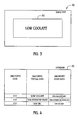
Figure 3 is a schematic of a display device of the radio unit; -
Figure 4 is a schematic of a database utilized in the vehicle diagnostic code communication system ofFigure 1 ; and -
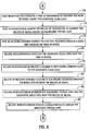
Figures 5-7 are flowcharts of a method for transmitting diagnostic data utilizing the vehicle diagnostic code communication system ofFigure 1 in accordance with another exemplary embodiment. - Referring to
Figure 1 , a vehicle diagnosticcode communication system 10 for transmitting diagnostic information associated with a vehicle is shown. The vehicle diagnosticcode communication system 10 includes anengine control module 20, adiagnostic link connector 22, a vehicle diagnosticcode communication device 24, and aradio unit 42. - The
engine control module 20 is configured to generate signals having diagnostic codes indicative of vehicle engine operation. Themodule 20 sends the signals to thediagnostic link connector 22. - The
diagnostic link connector 22 is operably coupled to theengine control module 20. Thediagnostic link connector 22 receives signals having diagnostic codes from theengine control module 20 and sends the signals to the vehicle diagnosticcode communication device 24 via adiagnostic link connector 26. - The vehicle diagnostic
code communication device 24 is provided to receive signals having diagnostic codes, and to transmit RF signals having diagnostic textual data and diagnostic audio data relating to the diagnostic codes. The vehicle diagnosticcode communication device 24 includes thediagnostic link connector 26 configured to receive the signals indicating diagnostic codes from thediagnostic link connector 22. Thedevice 24 further includes amicroprocessor 28 operably coupled to thediagnostic link connector 26. Themicroprocessor 28 is configured to determine at least one of: (i) diagnostic textual data, and (ii) diagnostic audio data based on the diagnostic code of the received signal. - Referring to
Figure 4 , adatabase 32 utilized by the vehicle diagnosticcode communication device 24 is shown. In particular, themicroprocessor 28 determines the diagnostic textual data and the diagnostic audio data by accessing amemory device 30 having thedatabase 32. As shown, thedatabase 32 includes a record having the diagnostic code "014," the diagnostic textual data "low coolant," and diagnostic audio data stored in a file "low.cooland.wav." Thedatabase 32 further includes a record having the diagnostic code "016," the diagnostic textual data "low emissions value," and diagnostic audio data stored in a file "low.emissions.valve.wav." Thedatabase 32 further includes a record having the diagnostic code "018," the diagnostic textual data "low oil," and diagnostic audio data stored in a file "low.oil.wav." - Referring to
Figure 3 , for example, when theradio unit 42 receives an RF signal having the diagnostic code "014," themicroprocessor 43 can access the record having diagnostic code "014" in thedatabase 32 to retrieve the diagnostic textual data "low coolant." Thereafter, themicroprocessor 43 can induce thedisplay device 50 to display the diagnostic textual data "low coolant." - Referring to
Figure 1 , the vehicle diagnosticcode communication device 24 further includes anRF transmitter 34 operably coupled to themicroprocessor 28. Themicroprocessor 28 is configured to induce theRF transmitter 34 to transmit an RF signal having diagnostic audio data associated with the received diagnostic code. The vehicle diagnosticcode communication device 24 further includes anotherRF transmitter 36 operably coupled to themicroprocessor 28. Themicroprocessor 28 is further configured to induce theRF transmitter 36 to transmit an RF signal having diagnostic textual data associated with the received diagnostic code. The vehicle diagnosticcode communication device 24 further includes aswitch 38 operably coupled to themicroprocessor 28. Theswitch 38 is utilized to allow an operator to select a frequency of the RF signals transmitted by theRF transmitters device 24 further includes aswitch 40 operably coupled to themicroprocessor 28. Theswitch 40 is utilized to allow an operator to select a second frequency of the RF signals transmitted by theRF transmitters - Referring to
Figures 2 and3 , theradio unit 42 for receiving RF signals from the vehicle diagnosticcode communication device 24 is shown. Theradio unit 42 includes amicroprocessor 43,RF receivers display device 50, and aspeaker device 52. TheRF receiver 44 is configured to receive an RF signal having diagnostic textual data from theRF transmitter 36. TheRF receiver 46 is configured to receive an RF signal having diagnostic audio data from theRF transmitter 34. Themicroprocessor 43 is configured to induce thedisplay device 50 to display the diagnostic textual data in an RF signal received by theRF receiver 46. Themicroprocessor 43 is further configured to induce thespeaker device 52 to emit sound corresponding to the diagnostic audio data in an RF signal received by theRF receiver 46. - Referring to
Figures 5-7 , a method for transmitting diagnostic data utilizing the vehicle diagnosticcode communication system 10 will now be explained. - At
step 60, theengine control module 20 generates a signal that is associated with diagnostic code indicative of engine operation and sends the signal to thediagnostic link connector 22. - At
step 62, thediagnostic link connector 22 sends the signal associated with the diagnostic code to thediagnostic link connector 26 coupled to themicroprocessor 28. - At
step 64, themicroprocessor 28 accesses thedatabase 32 storing diagnostic textual data and diagnostic audio data to obtain the diagnostic textual data and the diagnostic audio data associated with the diagnostic code. - At
step 66, themicroprocessor 28 makes a determination as to whether theswitch 38 has been closed by a vehicle operator. If the value ofstep 66 equals "yes," the method advances tostep 68. Otherwise, the method advances tostep 86. - At
step 68, themicroprocessor 28 sets a transmission frequency of first and second RF signals to a first predetermined frequency. - At
step 70, themicroprocessor 28 induces theRF transmitter 34 to transmit the first RF signal having the diagnostic audio data. - At
step 72, themicroprocessor 28 induces theRF transmitter 36 to transmit the second RF signal having the diagnostic textual data. - At
step 74, thereceiver 42 operably coupled to themicroprocessor 43 in theradio unit 42 receives the first RF signal. - At
step 76, themicroprocessor 43 retrieves the diagnostic audio data from the first RF signal. - At
step 78, themicroprocessor 43 induces thespeaker 52 to emit sound corresponding to the diagnostic audio data. - At
step 80, theRF receiver 46 operably coupled to themicroprocessor 43 in theradio unit 42 receives the second RF signal. - At
step 82, themicroprocessor 43 retrieves the diagnostic textual data from the second RF signal. - At
step 84, themicroprocessor 43 induces thedisplay device 50 to display the diagnostic textual data. Afterstep 84, the method returns to step 60. - Referring again to step 66, if the value of
step 66 equals "no," the method advances to step 86. - At
step 86, themicroprocessor 28 makes a determination as to whether theswitch 40 has been closed by a vehicle operator. If the value ofstep 86 equals "yes," the method advances to step 88. Otherwise, the method returns to step 60. - At
step 88, themicroprocessor 28 sets a transmission frequency of third and fourth RF signals to a second predetermined frequency. - At
step 90, themicroprocessor 28 induces theRF transmitter 34 to transmit the third RF signal having the diagnostic audio data. - At
step 92, themicroprocessor 28 induces theRF transmitter 36 to transmit the fourth RF signal having the diagnostic textual data. - At
step 94, theRF receiver 44 operably coupled to themicroprocessor 43 in theradio unit 42 receives the third RF signal. - At
step 96, themicroprocessor 43 retrieves the diagnostic audio data from the third RF signal. - At
step 98, themicroprocessor 43 induces thespeaker 52 to emit sound corresponding to the diagnostic audio data. - At
step 100, theRF receiver 46 operably coupled to themicroprocessor 43 in theradio unit 42 receives the fourth RF signal. - At
step 102, the microprocessor 48 retrieves the diagnostic textual data and the diagnostic audio data from the fourth RF signal. - At
step 104, themicroprocessor 43 induces thedisplay device 50 to display the diagnostic textual data. Afterstep 104, the method returns to step 60. - The vehicle diagnostic code communication device and the method for transmitting diagnostic data represent a substantial advantage over other devices and methods. In particular, the vehicle diagnostic code communication device and method provide a technical effect of transmitting RF signals having diagnostic data.
- While the invention has been described with reference to exemplary embodiments, it will be understood by those skilled in the art that various changes may be made and equivalents may be substituted for elements thereof without departing from the scope of the invention. In addition, many modifications may be made to adapt a particular situation or material to the teachings of the invention without departing from the essential scope thereof. Therefore, it is intended that the invention not be limited to the particular embodiment disclosed for carrying this invention, but that the invention will include all embodiments falling within the scope of the appended claims. Moreover, the use of the terms first, second, etc. do not denote any order or importance, but rather the terms first, second, etc. are used to distinguish one element from another. Furthermore, the use of the terms a, an, etc. do not denote a limitation of quantity, but rather denote the presence of at least one of the referenced items.
Claims (10)
- A vehicle diagnostic code communication device (24), comprising:a diagnostic link connector (26) configured to receive signals indicating a diagnostic code associated with vehicle operation;a first microprocessor (28) operably coupled to the diagnostic link connector (26),the first microprocessor (28) configured to determine at least one of diagnostic textual data and diagnostic audio data based on the diagnostic code; anda first RF transmitter (34) operably coupled to the first microprocessor (28),the first microprocessor (28) further configured to induce the first RF transmitter (34) to transmit a first RF signal having at least one of the diagnostic textual data and the diagnostic audio data.
- The vehicle diagnostic code communication device (24) as set forth in claim 1, wherein the first microprocessor (28) is further configured to retrieve the diagnostic textual data and the diagnostic audio data from a database (32) utilizing the diagnostic code.
- The vehicle diagnostic code communication device (24) as set forth in claim 1, further comprising a second RF transmitter (36) operably coupled to the first microprocessor (28), the first microprocessor (28) further configured to induce the second RF transmitter (36) to transmit a second RF signal having at least one of the diagnostic textual data and the diagnostic audio data.
- The vehicle diagnostic code communication device (24) as set forth in claim 1, further comprising at least a first switch (38) operably coupled to the first microprocessor (28), the first switch (38) being utilized to select a first frequency of the first RF signal.
- A method for transmitting diagnostic data utilizing a vehicle diagnostic code communication device (24), the vehicle diagnostic code communication device (24) having a diagnostic link connector (26), a first RF transmitter (34), a first microprocessor (28) operably coupled to the diagnostic link connector (26) and the first RF transmitter (34), the method comprising:receiving a diagnostic code at the diagnostic link connector (26);determining at least one of diagnostic textual data and diagnostic audio data based on the diagnostic code, utilizing the first microprocessor (28); andinducing the first RF transmitter (34) to transmit a first RF signal having at least one of the diagnostic textual data and the diagnostic audio data, utilizing the first microprocessor (28).
- The method as set forth in claim 5, further comprising retrieving at least one of diagnostic textual data and diagnostic audio data from a database (32) based on the diagnostic code, utilizing the first microprocessor (28).
- The method as set forth in claim 5, further comprising inducing a second RF transmitter (36) to transmit a second RF signal having at least one of the diagnostic textual data and the diagnostic audio data, utilizing the first microprocessor (28).
- The method as set forth in claim 5, further comprising actuating a switch (38) operably coupled to the first microprocessor (28) to select a frequency of the first RF signal.
- The method as set forth in claim 5, further comprising:receiving the first RF signal at a first RF receiver (44), the first RF signal having the diagnostic textual data;retrieving the diagnostic textual data from the first RF signal, utilizing a second microprocessor (43) operably coupled to the first RF receiver (44); anddisplaying the diagnostic textual data on a display device (50) operably coupled to the second microprocessor (43).
- The method as set forth in claim 5, further comprising:receiving the first RF signal at a first RF receiver (46), the first RFsignal having diagnostic audio data;
retrieving the diagnostic audio data from the first RF signal, utilizing a second microprocessor (43) operably coupled to the first RF receiver (46); and
emitting sound corresponding to the diagnostic audio data utilizing a speaker (52) operably coupled to the second microprocessor (43).
Applications Claiming Priority (1)
| Application Number | Priority Date | Filing Date | Title |
|---|---|---|---|
| US11/675,174 US20080201032A1 (en) | 2007-02-15 | 2007-02-15 | Vehicle diagnostic code communication device and a method for transmitting diagnostic data utilizing the vehicle diagnostic code communication device |
Publications (2)
| Publication Number | Publication Date |
|---|---|
| EP1959400A2 true EP1959400A2 (en) | 2008-08-20 |
| EP1959400A3 EP1959400A3 (en) | 2009-10-21 |
Family
ID=39495461
Family Applications (1)
| Application Number | Title | Priority Date | Filing Date |
|---|---|---|---|
| EP08151081A Withdrawn EP1959400A3 (en) | 2007-02-15 | 2008-02-05 | Vehicle diagnostic code communication device and a method for transmitting diagnostic data utilizing the vehicle diagnostic code communication device |
Country Status (4)
| Country | Link |
|---|---|
| US (1) | US20080201032A1 (en) |
| EP (1) | EP1959400A3 (en) |
| CN (1) | CN101246370A (en) |
| BR (1) | BRPI0800095A (en) |
Cited By (2)
| Publication number | Priority date | Publication date | Assignee | Title |
|---|---|---|---|---|
| US11181905B2 (en) * | 2018-08-02 | 2021-11-23 | Motional Ad Llc | Teleoperation of autonomous vehicles |
| US11548531B2 (en) | 2019-05-28 | 2023-01-10 | Motional Ad Llc | Autonomous vehicle fleet management for reduced traffic congestion |
Families Citing this family (21)
| Publication number | Priority date | Publication date | Assignee | Title |
|---|---|---|---|---|
| US20110196679A1 (en) * | 2009-11-09 | 2011-08-11 | Essex Incorporated | Systems And Methods For Machine To Operator Communications |
| US8517337B2 (en) * | 2009-12-21 | 2013-08-27 | Whirlpool Corporation | Proximity sensor enabled substance communication coupling system |
| US8342480B2 (en) * | 2009-12-21 | 2013-01-01 | Whirlpool Corporation | Substance communicating device with mechanically energized connector |
| US8405253B2 (en) * | 2009-12-21 | 2013-03-26 | Whirlpool Corporation | Mechanically energized eService connector system |
| US20110148650A1 (en) * | 2009-12-21 | 2011-06-23 | Whirlpool Corporation | Mechanical Proximity Sensor Enabled Electromagnetic Service Connector System |
| US8528610B2 (en) * | 2009-12-21 | 2013-09-10 | Whirlpool Corporation | Mechanically energized substance communication coupling system |
| US20110153739A1 (en) * | 2009-12-21 | 2011-06-23 | Whirlpool Corporation | Proximity Sensor Enabled eService Connector System |
| US8439178B2 (en) * | 2009-12-21 | 2013-05-14 | Whirlpool Corporation | Proximity sensor enabled mechanical power coupling system |
| US8382065B2 (en) * | 2009-12-21 | 2013-02-26 | Whirlpool Corporation | Substance communicating device with mechanically energized connector system |
| US8387948B2 (en) * | 2009-12-21 | 2013-03-05 | Whirlpool Corporation | Mechanically energized substance communication coupling system |
| US9103578B2 (en) * | 2009-12-21 | 2015-08-11 | Whirlpool Corporation | Substance communicating device for coupling to a host |
| US20110148649A1 (en) * | 2009-12-21 | 2011-06-23 | Whirlpool Corporation | Proximity Sensor Enabled Electromagnetic Service Connector System |
| US8430221B2 (en) * | 2009-12-21 | 2013-04-30 | Whirlpool Corporation | Mechanically energized mechanical power coupling system |
| US20110148651A1 (en) * | 2009-12-21 | 2011-06-23 | Whirlpool Corporation | Substance Communicating Device with Sensor Enabled Connector |
| US8830660B2 (en) * | 2009-12-21 | 2014-09-09 | Whirlpool Corporation | Mechanical power service communicating device and system |
| US8745203B2 (en) * | 2009-12-21 | 2014-06-03 | Whirlpool Corporation | Mechanical proximity sensor enabled eService connector system |
| US8700809B2 (en) * | 2009-12-21 | 2014-04-15 | Whirlpool Corporation | Substance communicating device with activatable connector and cycle structure |
| DE102011100106A1 (en) * | 2011-04-30 | 2012-10-31 | Daimler Ag | System for diagnosing a component in a vehicle |
| US8509985B2 (en) * | 2011-05-25 | 2013-08-13 | GM Global Technology Operations LLC | Detecting anomalies in fault code settings and enhancing service documents using analytical symptoms |
| CA2868573C (en) | 2013-10-24 | 2017-09-12 | Alldata Llc | Vehicle diagnostic systems and methods |
| US9843877B2 (en) | 2015-12-31 | 2017-12-12 | Ebay Inc. | Sound recognition |
Family Cites Families (19)
| Publication number | Priority date | Publication date | Assignee | Title |
|---|---|---|---|---|
| GB2274042B (en) * | 1993-01-04 | 1997-03-12 | Intel Corp | Simultaneous transfer of control information with voice and data over a public switched telephone network line |
| US5742666A (en) * | 1994-10-05 | 1998-04-21 | Tele Digital Development, Inc. | Emergency mobile telephone |
| US6061561A (en) * | 1996-10-11 | 2000-05-09 | Nokia Mobile Phones Limited | Cellular communication system providing cell transmitter location information |
| US6073004A (en) * | 1996-12-17 | 2000-06-06 | Ericsson Inc. | Emergency call initiator |
| DE10007218B4 (en) * | 2000-02-17 | 2009-11-26 | Robert Bosch Gmbh | Method for event interpretation and issuing of operating instructions in motor vehicles |
| US6636790B1 (en) * | 2000-07-25 | 2003-10-21 | Reynolds And Reynolds Holdings, Inc. | Wireless diagnostic system and method for monitoring vehicles |
| US6642844B2 (en) * | 2000-08-22 | 2003-11-04 | Sivan Llc | Direct dispatcherless automatic vehicle-to-vehicle and non-vehicle to vehicle police/emergency medical service notification system for life threatening accidents, hijackings, thefts and medical emergencies |
| EP1233387A2 (en) * | 2001-02-19 | 2002-08-21 | Hitachi Kokusai Electric Inc. | Vehicle emergency reporting system and method |
| JP3721089B2 (en) * | 2001-03-01 | 2005-11-30 | 株式会社日立製作所 | Vehicle diagnostic system and automobile using the system |
| US6615137B2 (en) * | 2001-06-26 | 2003-09-02 | Medius, Inc. | Method and apparatus for transferring information between vehicles |
| DE10155550C1 (en) * | 2001-11-12 | 2003-10-02 | Harman Becker Automotive Sys | Method and emergency call device for triggering an emergency call from a vehicle |
| US20040036587A1 (en) * | 2002-07-05 | 2004-02-26 | Jefferson Derrick Howard | Vehicle collision detector and alert system |
| US20050043868A1 (en) * | 2003-07-09 | 2005-02-24 | Mitcham Arvon L. | Vehicle on-board reporting system for state emissions test |
| US7085680B2 (en) * | 2004-01-16 | 2006-08-01 | Innova Electronics Corporation | Vehicle diagnostic tool |
| JP4396361B2 (en) * | 2004-04-05 | 2010-01-13 | 株式会社日立製作所 | Communication terminal device |
| US7289024B2 (en) * | 2004-08-19 | 2007-10-30 | General Motors Corporation | Method and system for sending pre-scripted text messages |
| KR100843901B1 (en) * | 2004-12-04 | 2008-07-03 | 주식회사 현대오토넷 | Remote Vehicle Control System Using Telematics System and Its Control Method |
| US20060229777A1 (en) * | 2005-04-12 | 2006-10-12 | Hudson Michael D | System and methods of performing real-time on-board automotive telemetry analysis and reporting |
| US20070179800A1 (en) * | 2005-12-31 | 2007-08-02 | General Motors Corporation | Email-based command interface for a telematics-equipped vehicle |
-
2007
- 2007-02-15 US US11/675,174 patent/US20080201032A1/en not_active Abandoned
-
2008
- 2008-02-05 EP EP08151081A patent/EP1959400A3/en not_active Withdrawn
- 2008-02-13 BR BRPI0800095-6A patent/BRPI0800095A/en not_active IP Right Cessation
- 2008-02-14 CN CNA2008100808198A patent/CN101246370A/en active Pending
Cited By (2)
| Publication number | Priority date | Publication date | Assignee | Title |
|---|---|---|---|---|
| US11181905B2 (en) * | 2018-08-02 | 2021-11-23 | Motional Ad Llc | Teleoperation of autonomous vehicles |
| US11548531B2 (en) | 2019-05-28 | 2023-01-10 | Motional Ad Llc | Autonomous vehicle fleet management for reduced traffic congestion |
Also Published As
| Publication number | Publication date |
|---|---|
| US20080201032A1 (en) | 2008-08-21 |
| CN101246370A (en) | 2008-08-20 |
| EP1959400A3 (en) | 2009-10-21 |
| BRPI0800095A (en) | 2008-10-07 |
Similar Documents
| Publication | Publication Date | Title |
|---|---|---|
| EP1959400A2 (en) | Vehicle diagnostic code communication device and a method for transmitting diagnostic data utilizing the vehicle diagnostic code communication device | |
| US8594933B2 (en) | Transmission of sensor data based on geographical navigation data | |
| EP1191761B1 (en) | Storage system for mobile communication device data | |
| CA2523204C (en) | Remote tire monitoring systems tool | |
| US7518495B2 (en) | Universal tire pressure monitor | |
| EP2668726B1 (en) | Wireless trainable transceiver device with integrated interface and gps modules | |
| US8670929B2 (en) | System and method for tracking a vehicle based on driver status | |
| US7639122B2 (en) | Tire pressure monitor system tool with vehicle entry system | |
| US7864070B2 (en) | System and method for training a trainable transmitter | |
| US9269201B2 (en) | Tire pressure monitor system tool with re-learn and diagnostic procedures | |
| US8035499B2 (en) | Tire pressure monitor system module | |
| US20050043868A1 (en) | Vehicle on-board reporting system for state emissions test | |
| EP1953722A2 (en) | Vehicle emergency communication device and a method for transmitting emergency textual data utilizing the vehicle emergency communication device | |
| WO2004034352A1 (en) | System and method for wireless control of remote electronic systems including functionality based on location | |
| US20070050126A1 (en) | Vehicle management system and method in telematics system | |
| CN102541588A (en) | Method of application control | |
| WO2021171151A1 (en) | Scanning method and device for tire pressure monitoring system (tpms) protocols | |
| US20110093160A1 (en) | Vehicle check in method | |
| US7623025B2 (en) | Tire pressure monitor initiation tool with vehicle data interface | |
| US20090024317A1 (en) | System for gathering and distributing location information of vehicles | |
| US7672780B2 (en) | Navigation system using radio frequency identification system and method for displaying construction area road | |
| KR101475351B1 (en) | Tag location guidance method and tag location guidance system of communication terminal | |
| US9539868B2 (en) | Method and system for transmitting an identifier of a valve of a wheel of a vehicle to a receiver on board this vehicle | |
| US8862318B2 (en) | Method for teaching an aftermarket accessory component, and an aftermarket accessory component configured to learn | |
| US20130142354A1 (en) | Method and apparatus for transmission of song identifications |
Legal Events
| Date | Code | Title | Description |
|---|---|---|---|
| PUAI | Public reference made under article 153(3) epc to a published international application that has entered the european phase |
Free format text: ORIGINAL CODE: 0009012 |
|
| AK | Designated contracting states |
Kind code of ref document: A2 Designated state(s): AT BE BG CH CY CZ DE DK EE ES FI FR GB GR HR HU IE IS IT LI LT LU LV MC MT NL NO PL PT RO SE SI SK TR |
|
| AX | Request for extension of the european patent |
Extension state: AL BA MK RS |
|
| PUAL | Search report despatched |
Free format text: ORIGINAL CODE: 0009013 |
|
| AK | Designated contracting states |
Kind code of ref document: A3 Designated state(s): AT BE BG CH CY CZ DE DK EE ES FI FR GB GR HR HU IE IS IT LI LT LU LV MC MT NL NO PL PT RO SE SI SK TR |
|
| AX | Request for extension of the european patent |
Extension state: AL BA MK RS |
|
| AKX | Designation fees paid | ||
| REG | Reference to a national code |
Ref country code: DE Ref legal event code: 8566 |
|
| STAA | Information on the status of an ep patent application or granted ep patent |
Free format text: STATUS: THE APPLICATION IS DEEMED TO BE WITHDRAWN |
|
| 18D | Application deemed to be withdrawn |
Effective date: 20100422 |