EP1959395A1 - Method of processing a radon data based image function and imaging method - Google Patents
Method of processing a radon data based image function and imaging method Download PDFInfo
- Publication number
- EP1959395A1 EP1959395A1 EP07003163A EP07003163A EP1959395A1 EP 1959395 A1 EP1959395 A1 EP 1959395A1 EP 07003163 A EP07003163 A EP 07003163A EP 07003163 A EP07003163 A EP 07003163A EP 1959395 A1 EP1959395 A1 EP 1959395A1
- Authority
- EP
- European Patent Office
- Prior art keywords
- image
- projection
- image function
- function
- values
- Prior art date
- Legal status (The legal status is an assumption and is not a legal conclusion. Google has not performed a legal analysis and makes no representation as to the accuracy of the status listed.)
- Withdrawn
Links
Images


Classifications
-
- G—PHYSICS
- G06—COMPUTING OR CALCULATING; COUNTING
- G06T—IMAGE DATA PROCESSING OR GENERATION, IN GENERAL
- G06T12/00—Tomographic reconstruction from projections
- G06T12/20—Inverse problem, i.e. transformations from projection space into object space
Definitions
- the present invention relates to a method of processing an image function based on Radon data, which comprise a plurality of projection functions measured corresponding to a plurality of predetermined projection directions. Furthermore, the present invention relates to a method and a device for imaging a region of investigation, wherein the above image function processing method is applied.
- the image function obtained with the OPED reconstruction methods is a continuous function.
- the continuous function is subjected to a discretization for presenting a visualized image.
- displaying the image function on a computer display or printing the image function with a digital data printer requires a discretization of the image function according to the screen resolution of the display or printer.
- the continuous image function is discretized with a pattern of 512 * 512 or 1024 * 1024 pixels.
- One value of the image function converted into a gray value is assigned to each of the pixels, respectively.
- the conventional imaging techniques have a common disadvantage, which is associated with the discretization of the continuous image function.
- the local resolution of the visualized image is essentially smaller compared to a space frequency of local image function features.
- the pixel size of the visualized image is essentially larger compared to the size of local image function features.
- the conventional discretization comprises a convolution of the image function with a Dirac function (delta function, unit impulse function) at each pixel, local features of the continuous image function can introduce distortions into the visualized image.
- artifacts can occur in the image in particular if local features of the image function have a characteristic period of high-frequency components of the image function being comparable with the pattern of discretization.
- the objective of the invention is to provide improved methods of processing image functions based on Radon data avoiding the disadvantages of conventional image processing techniques.
- a further aspect of the objective of the invention is to provide an improved imaging method avoiding the disadvantages of the conventional imaging methods based on the collection of Radon data.
- Another objective of the invention is to provide improved devices adapted for imaging a region of investigation by reconstructing and processing measured Radon data.
- an image processing method for providing a digitized approximation of an image function includes the step of calculating pixel values being determined from at least two image function values within a pixel size of the respective pixel.
- improved pixel values are obtained, wherein influences due to the stochastic occurrence of local features of the image function at the sampling position with the conventionally used Dirac function are suppressed or even completely avoided.
- the pixel values are determined by at least two local features of the image function within the respective pixel size. The inventors have found that pseudo-information caused by single sampling with the Dirac function can be reduced even with the consideration of two image function values within the pixel size. Considering at least two image function values yields an additional integration within the pixel size, which allows to avoid artefacts in the image.
- a continuously defined image function is digitized.
- the term "continuous image function" includes both analytical representations of the image function or quasi-continuous image functions.
- a quasi-continuous image function is represented by a discretized data set of image function values each of which representing a local region (or: area) being essentially smaller compared with the pixel size of the digitized representation of the image function to be obtained.
- the local region is smaller by a factor of at least 2, preferably at least 10, e. g. 100, compared with a digitized image pixel size.
- a corresponding number of image function values represent the course of the image function within each digitized image pixel.
- an imaging method for imaging a region of investigation of an object includes the steps of measuring Radon data with an imaging device, reconstructing an image function derived from the Radon data, and subjecting the image function to an image processing method according to the above first aspect of the invention.
- An essential advantage of the imaging method of the invention is given by the fact that the improved discretization of the image function is combined with the primary image data collection.
- an imaging device arranged for imaging a region of investigation of an object comprises a measuring device adapted for measuring projection functions, a reconstruction circuit adapted for reconstructing an image function derived from the measured projection functions, and an image processing circuit adapted for processing the image function with a method according to the above first aspect.
- the pixel values are determined by more than two image function values, e. g. at least 4, in particular more than 9 image function values within the pixel size. Accordingly, the integration of local image function features within each pixel can be further improved. According to a particularly preferred embodiment, the number of image function values considered within the pixel size is further increased so that the pixel values can be determined by evaluating an approximation of the image function resulting of a convolution of the image function with a predetermined filter function within the pixel size of the respective pixel.
- the filter function results in an integration over all local image function features, so that the deletion of artefacts can be improved.
- the filter function comprises a step function covering the whole pixel size of the respective pixel. Accordingly, all image function values within the pixel size contribute to the pixel value assigned to the respective pixel.
- the image function processed according to the invention can be reconstructed from Radon data on the basis of any conventional reconstruction method resulting in a continuous image function. Particular advantages are obtained if the image function has been determined with the OPED algorithm noted above. While the OPED algorithm results in continuous image functions with detailed local features, the inventive discretization of the image function results in particular strong improvements of the image quality and suppression of image errors. Accordingly, the image function digitized according to the invention is preferably provided as a sum of polynomials multiplied with values of the Radon data projection functions.
- the reconstruction circuit of the imaging device of the invention is preferably adapted for reconstructing the image function as a sum of polynomials multiplied with values of the measured protection functions.
- FFT procedure Fast Fourier transform procedure
- the projection functions measured with the imaging device of the invention comprise discrete projection profiles, each discrete projection profile comprising projection values ⁇ ( ⁇ ,j) corresponding to a plurality of projection lines (j) with the same projection direction ( ⁇ ) .
- the image function reconstruction is essentially accelerated.
- the inventive reconstruction needs only 2mlog 2 2m operations instead of (2m) 2 operations.
- the hardware circuit provided for calculating the protection sum has an improved design.
- the FAST-OPED algorithm has been proved to converge uniformly on any compact subset in the disk and the numerical test has shown that it reconstructs images accurately and as good as the conventional OPED algorithm.
- the FAST OPED algorithm with the interpolation step is not only much faster, it also shares main merits of the conventional OPED algorithm.
- the implementation of the FAST-OPED algorithm is not restricted to the combination with the image processing method according to the above first aspect of the invention.
- the FAST-OPED algorithm can be generally used for reconstructing Radon-based data obtained as described e. g. in EP 040 310 43.5 . Accordingly the FAST-OPED algorithm represents a further independent aspect of the invention.
- the imaging method of the invention preferably comprises the steps of arranging an object in the measuring device of the imaging device, subjecting the object to an energy input directed along the plurality of predetermined projection directions, and measuring the projection profiles. At least one of the object and the measuring device can be translated in a predetermined direction during the step of subjecting the object to the energy input for obtaining helical projection data.
- the digitized image of the image function is displayed as a visualized image to be obtained.
- the term "displaying" refers to any type of visualized presentation, like e. g. presenting on a image display device or in printed form.
- the invention can be used for generating images from Radon data or Radon-like data. It is an essential advantage of the invention, that this image generation can be used in various applications like many applications in medical imaging, for example CT, PET, SPECT, gamma-camera imaging etc.. However, there are a lot more possible applications like ultrasound tomographic imaging, light tomography, any multidimensional imaging for industrial testing or biological research and so on.
- the image function is determined from Radon data measured in an X-ray computer tomography (CT) device, an ultrasound tomography device, a PET imaging device, a light tomography device, a Gamma-ray imaging device, a SPECT imaging device, a neutron based transmission detection system, or an electrical impedance tomography device.
- CT computer tomography
- the object under investigation preferably comprises a biological organism or a part thereof, a fluid composition, a solid material, a work-piece, and/or an object to be investigated for security reasons.
- a digital storage medium or a computer program product with electronically readable data comprising a sum of polynomials, said data being able to interact with an imaging device arranged implementing a method according to the invention, a computer program residing on a computer-readable medium, with a program code for carrying out the method of the invention, and an apparatus comprising a computer-readable storage medium containing program instructions for carrying out the method of the invention.
- the invention is described in the following with reference to the preferred application in the field of X-ray based computer tomography. It is emphasized that the invention can be implemented in an analogous way with the application of other types of energy input beams (like e.g. neutrons or light, e.g. in the VIS or IR range) and/or other types of projection-based imaging (like e.g. projection radiography). Furthermore, the following description of the preferred embodiments mainly refers to the image function discretization. Details of the CT devices used for implementing the invention are not described as long as they are known from conventional CT devices. Details and terms of the OPED algorithm are described in EP 040 310 43.5 , which is incorporated into the present specification by reference.
- the basic steps of an image function processing method according to the invention comprise step 100 of providing an image function, step 200 of determining discretized pixel values and (optionally) step 300 of representing a digitized image on the basis of the discretized pixel values.
- Figure 2 illustrates steps of an embodiment of the imaging method according to the invention.
- Step 100 can be implemented in dependence on the particular application of the image function processing method.
- step 100 can comprise in particular sub-steps 110, 120 and 130 as illustrated in Figure 2 .
- These sub-steps schematically represent the measurement and OPED-based reconstruction of Radon data as described in EP 040 310 43.5 .
- step 100 can comprise a provision of the image function as an analytical expression or as a quasi-continuous data set.
- Step 300 is not a necessary feature of the invention.
- the pixel values determined with step 200 can be stored in a data storage of e.g. an imaging device or another image processor.
- sub-steps 110, 120 and 130 include directing a plurality of X-ray beams at predetermined projection directions through a region of investigation, determining projection profiles comprising attenuation values measured with the plurality of X-ray beams, and reconstructing an image function f derived from the projection profiles.
- step 200 is described with reference to the schematic illustration in Figures 3 and 4.
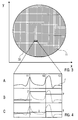
- Figure 3 illustrates a pixel array 10 including a plurality of pixels 11 being arranged for representing an image function f .
- Figure 4A represents an enlarged view of three particular pixels 11, 12 and 13 with an exemplary image function f .
- a particular approach for selecting a suitable number of pixels in pixel array 10 is determined by the measurement conditions of the imaging device used for providing the image function.
- the imaging device comprises a CT device adapted for collecting Radon data of a region of investigation of 30 cm and the detector device has a resolution of 0,5 mm
- about 600 ⁇ 600 pixels 11 can be used for representing a digitized image of the region of investigation.
- Pixel array 10 comprises e.g. pixels of a display device, like a LED display with a typical pixel size of about 200 ⁇ m, or a pixel distribution, which can be printed with a digital printer having a pixel size of e.g. 80 ⁇ m.
- pixel values 1', 2' and 3' are obtained by a convolution of the image function f with the Dirac function located e.g. at a left border of each pixel.
- the pixel values 1', 2' and 3' are identical with the image function values at the pixel borders.
- This result has a stochastic character as the pixel values are determined by local feature of the image function only.
- the conventional technique is replaced by a determination of the pixel values in dependence on at least two image function values within the size of each pixel as shown in Figure 4C .
- the pixel values 1, 2 and 3 are determined by a convolution of the image function f with a filter function comprising e.g. a step function within the pixel size of the respective pixel.
- pixel values 1, 2 and 3 represent an improved averaged approximation of of the image function values within each pixel 11, 12 or 13. Calculation of digitized pixel values is obtained in two or more image dimensions in an analogue manner.
- the additional integration of the image function in each pixel requires additional processing time.
- the additional processing time is preferably compensated according to the invention by a reconstruction of the image function with a modified OPED algorithm (so-called FAST-OPED), which is described in the following.
- an approximation of the image function can be directly calculated as a double sum A 2m from measured projection values.
- a 2m The structure of the A 2m is used to implement Fast Fourier Transformation (FFT) once in a straightforward manner.
- FFT Fast Fourier Transformation
- the values of S k, ⁇ can be evaluated by FFT for discrete sine transform.
- the main step of the OPED algorithm lies in the evaluation of the above double sum, which can be considered as a back projection step.
- N 2m + 1.
- the evaluation of the matrix S k, ⁇ costs 'O( N 2 log N ) operations (flops).
- the evaluation of the double sum costs 'O( N 2 ) operations.
- the cost of evaluation on a grid of M x M is ' O( N 2 ( M 2 + log N ).
- M ⁇ N then the cost is ' O( N 4 ) .
- the main operation cost is at the evaluation of the double sums at the grid points. In other words, the main cost lies in the back projection step.
- the inner sum can be evaluated by FFT for discrete sine transform at certain points, which suggests that an interpolation step is introduced to take advantage of the fast evaluation by FFT.
- FFT discrete sine transform
- the black points illustrate ⁇ v and the hollow points mean ⁇ (x,y).
- a linear interpolation is preferably used.
- the integer l is chosen such that ⁇ v ( x,y ) lies between ⁇ l and ⁇ l + 1 and the value of the linear interpolation between ⁇ l,v and ⁇ l + 1v is used as an approximation to the inner sum of (5).
- the algorithm uses FFT twice, the final sum in step 3 is a single sum whose evaluation costs 'O(N) operations. Hence, the cost of evaluations on an M x M grid with M ⁇ N is ' O(N 3 ) , which is in the same order of magnitude as the FBP algorithm.
- FFT for discrete sine transform in the package FFTW http://www.fftw.org/
- the numerical example is conducted on a so-called Shepp-Logan head phantom. This is an analytic phantom, highly singular, as the image contains jumps at the boundary of every ellipse in the image, include the one on the boundary.
- the function that represents the image is a step function, which is not continuous at the boundary of the ellipses.
- the reconstruction was carried out on a CELSIUS R610 computer with two Intel Xenon(TM) CPU, each 3065 MHz, and 4 GB RAM (code is written in C language).
- TM Intel Xenon
- 4 GB RAM code is written in C language.
- the reconstruction took 344 seconds, in which more than 95% of the time is used on the back projection step.
- the reconstruction took merely 13 seconds, an improvement of more that 26 times. Furthermore, the two images show almost no visual difference.
- FAST OPED is slightly worse in relative least square error, but slightly better in mean error.
- the order of magnitude of the error is the same. The difference is practically negligible.
- FIG. 6 schematically illustrates an embodiment of the imaging device 100.
- the imaging device 100 includes the measuring device with an energy generator 200 and the detector device 300, and an reconstruction circuit 400 being connected with the measuring device.
- a holding device 500 is provided, which is e.g. a carrier table as it is known from CT systems or any other carrier or substrate holder for arranging an object under investigation in the measuring device and for adjusting the geometry of the object relative to the energy generator 200 and the detector device 300.
- Further components like a control device, a display device etc. (not shown) are provided for as they are known per se from prior art devices.
- the energy generator 200 comprises an energy input source 210, like e.g. a movable X-ray arranged on a source carrier 220 (e.g. a guide rail) as it is known from conventional CT devices.
- the detector device comprises a sensor array 310 which is movably arranged on the source carrier 220 in opposite relationship relative to the energy input source 210.
- the projection direction through the ROI can be set by rotating the combination of components 210, 310 around the holding device 500.
- the source carrier 220 is illustrated as a circle allowing a rotation of the energy generator 200 and the detector device 300 around an object.
- the source carrier can have an ellipse shape or another shape. This can represent an advantage in terms of an adaptation to the geometry of the object to be investigated.
- the reconstruction circuit 400 being connected with the measuring device 200, 300 is adapted for reconstructing an image function f as a sum of polynomials multiplied with values of the measured projection functions.
- the reconstruction circuit 400 includes an image processing circuit 410 adapted for discretizing the image function f with the image processing method according to the above first aspect of the invention.
- the image processing circuit 410 is implemented e.g. with a microprocessor comprising a computer-readable storage medium containing program instructions for carrying out the inventive.
Landscapes
- Physics & Mathematics (AREA)
- General Physics & Mathematics (AREA)
- Engineering & Computer Science (AREA)
- Theoretical Computer Science (AREA)
- Image Processing (AREA)
- Apparatus For Radiation Diagnosis (AREA)
Abstract
An image processing method for providing a digitized image as an approximation of an image function f , wherein the digitized image comprises a plurality of pixels with a predetermined pixel size, comprises the steps of providing the image function f from Radon data comprising a plurality of projection functions measured corresponding to a plurality of predetermined projection directions (ν), and determining pixel values from the image function, the pixel values representing the digitized image to be obtained, wherein the pixel values are determined in dependence on at least two image function values within the pixel size of the respective pixel. Furthermore, an imaging method and an imaging device using the image processing method are described.
Description
- The present invention relates to a method of processing an image function based on Radon data, which comprise a plurality of projection functions measured corresponding to a plurality of predetermined projection directions. Furthermore, the present invention relates to a method and a device for imaging a region of investigation, wherein the above image function processing method is applied.
- The non-destructive investigation of samples is an important object in various technical fields like material sciences, medical examinations, archaeology, construction technique, techniques concerning security matters etc.. One approach for obtaining an image of a sample e.g. by computer tomography (CT) is based on an irradiation trough a sample plane from different projection directions with X-rays, followed by the reconstruction of the sample plane on the basis of attenuation data measured at different directions. The entirety of the measured attenuation data can be described in terms of so-called Radon data in a Radon space.
- Different reconstruction methods for Radon data are known today, which in particular comprise iterative reconstruction methods and filtered back-projection methods. A further improved method of reconstructing image functions from Radon data is described in
EP 04031043.5 - The image function obtained with the OPED reconstruction methods is a continuous function. As typical devices for image visualization have a digitized output, the continuous function is subjected to a discretization for presenting a visualized image. As an example, displaying the image function on a computer display or printing the image function with a digital data printer requires a discretization of the image function according to the screen resolution of the display or printer. As an example, the continuous image function is discretized with a pattern of 512 * 512 or 1024 * 1024 pixels. One value of the image function converted into a gray value is assigned to each of the pixels, respectively.
- The conventional imaging techniques have a common disadvantage, which is associated with the discretization of the continuous image function. Usually, the local resolution of the visualized image is essentially smaller compared to a space frequency of local image function features. The pixel size of the visualized image is essentially larger compared to the size of local image function features. As the conventional discretization comprises a convolution of the image function with a Dirac function (delta function, unit impulse function) at each pixel, local features of the continuous image function can introduce distortions into the visualized image. As a result, artifacts can occur in the image in particular if local features of the image function have a characteristic period of high-frequency components of the image function being comparable with the pattern of discretization.
- The above disadvantage is associated not only with the conventional CT imaging, but also with all available OPED reconstruction and image processing methods based on the collection of Radon data, like e. g. neutron transmission imaging, ultrasound tomography etc..
- The objective of the invention is to provide improved methods of processing image functions based on Radon data avoiding the disadvantages of conventional image processing techniques. A further aspect of the objective of the invention is to provide an improved imaging method avoiding the disadvantages of the conventional imaging methods based on the collection of Radon data. Another objective of the invention is to provide improved devices adapted for imaging a region of investigation by reconstructing and processing measured Radon data.
- The above objectives are achieved with methods or devices comprising the features of the independent claims. Advantageous embodiments and applications of the invention are defined in the dependent claims.
- According to a first general aspect of the invention, an image processing method for providing a digitized approximation of an image function includes the step of calculating pixel values being determined from at least two image function values within a pixel size of the respective pixel.
- As an essential advantage, improved pixel values are obtained, wherein influences due to the stochastic occurrence of local features of the image function at the sampling position with the conventionally used Dirac function are suppressed or even completely avoided. The pixel values are determined by at least two local features of the image function within the respective pixel size. The inventors have found that pseudo-information caused by single sampling with the Dirac function can be reduced even with the consideration of two image function values within the pixel size. Considering at least two image function values yields an additional integration within the pixel size, which allows to avoid artefacts in the image.
- According to the invention, a continuously defined image function is digitized. The term "continuous image function" includes both analytical representations of the image function or quasi-continuous image functions. A quasi-continuous image function is represented by a discretized data set of image function values each of which representing a local region (or: area) being essentially smaller compared with the pixel size of the digitized representation of the image function to be obtained. As an example, the local region is smaller by a factor of at least 2, preferably at least 10, e. g. 100, compared with a digitized image pixel size. A corresponding number of image function values represent the course of the image function within each digitized image pixel.
- According to a second general aspect of the invention, an imaging method for imaging a region of investigation of an object is proposed, which imaging method includes the steps of measuring Radon data with an imaging device, reconstructing an image function derived from the Radon data, and subjecting the image function to an image processing method according to the above first aspect of the invention. An essential advantage of the imaging method of the invention is given by the fact that the improved discretization of the image function is combined with the primary image data collection.
- According to a third general aspect of the invention, an imaging device arranged for imaging a region of investigation of an object comprises a measuring device adapted for measuring projection functions, a reconstruction circuit adapted for reconstructing an image function derived from the measured projection functions, and an image processing circuit adapted for processing the image function with a method according to the above first aspect.
- According to a preferred embodiment of the image processing method of the invention, the pixel values are determined by more than two image function values, e. g. at least 4, in particular more than 9 image function values within the pixel size. Accordingly, the integration of local image function features within each pixel can be further improved. According to a particularly preferred embodiment, the number of image function values considered within the pixel size is further increased so that the pixel values can be determined by evaluating an approximation of the image function resulting of a convolution of the image function with a predetermined filter function within the pixel size of the respective pixel. Advantageously, the filter function results in an integration over all local image function features, so that the deletion of artefacts can be improved. As an example, the filter function comprises a step function covering the whole pixel size of the respective pixel. Accordingly, all image function values within the pixel size contribute to the pixel value assigned to the respective pixel.
- The image function processed according to the invention can be reconstructed from Radon data on the basis of any conventional reconstruction method resulting in a continuous image function. Particular advantages are obtained if the image function has been determined with the OPED algorithm noted above. While the OPED algorithm results in continuous image functions with detailed local features, the inventive discretization of the image function results in particular strong improvements of the image quality and suppression of image errors. Accordingly, the image function digitized according to the invention is preferably provided as a sum of polynomials multiplied with values of the Radon data projection functions. Correspondingly, the reconstruction circuit of the imaging device of the invention is preferably adapted for reconstructing the image function as a sum of polynomials multiplied with values of the measured protection functions.
- As the discretization of the image function requires additional processing time, the complete time necessary for presenting a digitized image of a region under investigation may be increased. Advantageously, this increase of processing time can be compensated if a Fast Fourier transform procedure (FFT procedure) is implemented into the reconstruction of the image function as follows.
- The projection functions measured with the imaging device of the invention comprise discrete projection profiles, each discrete projection profile comprising projection values γ(ν,j) corresponding to a plurality of projection lines (j) with the same projection direction (ν). The image function ƒ can be represented as a projection sum


EP 04031043.5 - According to the preferred embodiment of the invention (so-called FAST-OPED algorithm), the image function f is determined by the steps of determining an intermediate sum


- With the application of the Sinus Transform procedure, the image function reconstruction is essentially accelerated. In the best case, the inventive reconstruction needs only 2mlog22m operations instead of (2m)2 operations. Typically, the processing time e. g. for m = 512 can be reduced with this embodiment by a factor of 100. Furthermore, the hardware circuit provided for calculating the protection sum has an improved design.
- Preferably, the intermediate sum is determined with


- Preferably, the above implementation of the Sinus Transform procedure, the determination of the image function comprises the step of determining

- The FAST-OPED algorithm has been proved to converge uniformly on any compact subset in the disk and the numerical test has shown that it reconstructs images accurately and as good as the conventional OPED algorithm. The FAST OPED algorithm with the interpolation step is not only much faster, it also shares main merits of the conventional OPED algorithm.
- The implementation of the FAST-OPED algorithm is not restricted to the combination with the image processing method according to the above first aspect of the invention. In fact, the FAST-OPED algorithm can be generally used for reconstructing Radon-based data obtained as described e. g. in
EP 040 310 43.5 - The imaging method of the invention preferably comprises the steps of arranging an object in the measuring device of the imaging device, subjecting the object to an energy input directed along the plurality of predetermined projection directions, and measuring the projection profiles. At least one of the object and the measuring device can be translated in a predetermined direction during the step of subjecting the object to the energy input for obtaining helical projection data.
- Preferably, the digitized image of the image function is displayed as a visualized image to be obtained. Generally, the term "displaying" refers to any type of visualized presentation, like e. g. presenting on a image display device or in printed form.
- Generally, the invention can be used for generating images from Radon data or Radon-like data. It is an essential advantage of the invention, that this image generation can be used in various applications like many applications in medical imaging, for example CT, PET, SPECT, gamma-camera imaging etc.. However, there are a lot more possible applications like ultrasound tomographic imaging, light tomography, any multidimensional imaging for industrial testing or biological research and so on. Preferably, the image function is determined from Radon data measured in an X-ray computer tomography (CT) device, an ultrasound tomography device, a PET imaging device, a light tomography device, a Gamma-ray imaging device, a SPECT imaging device, a neutron based transmission detection system, or an electrical impedance tomography device. Accordingly, the object under investigation preferably comprises a biological organism or a part thereof, a fluid composition, a solid material, a work-piece, and/or an object to be investigated for security reasons.
- Further subjects of the invention are a digital storage medium or a computer program product with electronically readable data comprising a sum of polynomials, said data being able to interact with an imaging device arranged implementing a method according to the invention, a computer program residing on a computer-readable medium, with a program code for carrying out the method of the invention, and an apparatus comprising a computer-readable storage medium containing program instructions for carrying out the method of the invention.
- Further details and advantages of the invention are described in the following with reference to the attached drawings, which show in:
- Figure 1
- a flow chart illustrating an embodiment of the image function processing method according to the invention;
- Figure 2
- a flow chart illustrating an embodiment of the imaging method according to the invention;
- Figures 3 and 4:
- schematic illustrations of determining pixel values according to the invention;
- Figure 5
- a schematic illustration of an interpolation step included in the image reconstruction algorithm used according to the invention; and
- Figure 6
- a schematic illustration of an embodiment of an imaging device according to the invention.
- The invention is described in the following with reference to the preferred application in the field of X-ray based computer tomography. It is emphasized that the invention can be implemented in an analogous way with the application of other types of energy input beams (like e.g. neutrons or light, e.g. in the VIS or IR range) and/or other types of projection-based imaging (like e.g. projection radiography). Furthermore, the following description of the preferred embodiments mainly refers to the image function discretization. Details of the CT devices used for implementing the invention are not described as long as they are known from conventional CT devices. Details and terms of the OPED algorithm are described in
EP 040 310 43.5 - According to
Figure 1 , the basic steps of an image function processing method according to the invention comprisestep 100 of providing an image function, step 200 of determining discretized pixel values and (optionally)step 300 of representing a digitized image on the basis of the discretized pixel values.Figure 2 illustrates steps of an embodiment of the imaging method according to the invention. Step 100 can be implemented in dependence on the particular application of the image function processing method. As an example, step 100 can comprise inparticular sub-steps Figure 2 . These sub-steps schematically represent the measurement and OPED-based reconstruction of Radon data as described inEP 040 310 43.5 step 200 can be stored in a data storage of e.g. an imaging device or another image processor. - In particular, sub-steps 110, 120 and 130 include directing a plurality of X-ray beams at predetermined projection directions through a region of investigation, determining projection profiles comprising attenuation values measured with the plurality of X-ray beams, and reconstructing an image function f derived from the projection profiles.
- Further details of
step 200 are described with reference to the schematic illustration inFigures 3 and 4. Figure 3 illustrates apixel array 10 including a plurality ofpixels 11 being arranged for representing an image function f.Figure 4A represents an enlarged view of threeparticular pixels - Typically, a particular approach for selecting a suitable number of pixels in
pixel array 10 is determined by the measurement conditions of the imaging device used for providing the image function. As an example, if the imaging device comprises a CT device adapted for collecting Radon data of a region of investigation of 30 cm and the detector device has a resolution of 0,5 mm, about 600 · 600pixels 11 can be used for representing a digitized image of the region of investigation.Pixel array 10 comprises e.g. pixels of a display device, like a LED display with a typical pixel size of about 200 µm, or a pixel distribution, which can be printed with a digital printer having a pixel size of e.g. 80 µm. - According to the conventional techniques, pixel values 1', 2' and 3' (
Figure 4B ) are obtained by a convolution of the image function f with the Dirac function located e.g. at a left border of each pixel. As a result, the pixel values 1', 2' and 3' are identical with the image function values at the pixel borders. This result has a stochastic character as the pixel values are determined by local feature of the image function only. The conventional technique is replaced by a determination of the pixel values in dependence on at least two image function values within the size of each pixel as shown inFigure 4C . - According to
Figure 4C , the pixel values 1, 2 and 3 are determined by a convolution of the image function f with a filter function comprising e.g. a step function within the pixel size of the respective pixel. As the result, pixel values 1, 2 and 3 represent an improved averaged approximation of of the image function values within eachpixel - The additional integration of the image function in each pixel requires additional processing time. The additional processing time is preferably compensated according to the invention by a reconstruction of the image function with a modified OPED algorithm (so-called FAST-OPED), which is described in the following.
- According to the OPED algorithm described in
EP 040 310 43.5 


- The structure of the A2m is used to implement Fast Fourier Transformation (FFT) once in a straightforward manner. With the definition


- Thus, the main step of the OPED algorithm lies in the evaluation of the above double sum, which can be considered as a back projection step. Let N = 2m + 1. Then the evaluation of the matrix Sk,ν costs 'O(N2 logN) operations (flops). The evaluation of the double sum costs 'O(N2 ) operations. Hence, the cost of evaluation on a grid of M x M is 'O(N2 (M2 + logN). In particular, if M ~ N, then the cost is 'O(N4 ). The main operation cost is at the evaluation of the double sums at the grid points. In other words, the main cost lies in the back projection step.
- Unlike the Filtered Back Projection algorithm, the sum in (4) does not contain a discrete convolution that can be evaluated via FFT. However, the formula of Uk, in (2) allows to write

where
- The inner sum can be evaluated by FFT for discrete sine transform at certain points, which suggests that an interpolation step is introduced to take advantage of the fast evaluation by FFT. With further detail, it is defined

Figure 5 , the black points illustrate θv and the hollow points mean θ (x,y). - The FFT for discrete sine transforms can be used to evaluate the numbers

- For the interpolation step, a linear interpolation is preferably used. For a given (x,y), the integer l is chosen such that θv (x,y) lies between ξ l and ξ l+1 and the value of the linear interpolation between αl,v and α l+1v is used as an approximation to the inner sum of (5). The linear interpolation is given by

where ξ1 ≤ θ ≤ ξ l+1 . Then the fast implementation of OPED algorithm (step 130 inFigure 2 ) comprises the following steps. -
Step 1. For each v = 0, ... 2m, FFT is used to compute for each k = 0, ... 2m, (m: positive integer)
-
Step 2. For each L = 0, 1, ... 2m - 1, FFT is used to compute
-
Step 3. For each reconstruction point (x,y) inside a region of investigation (disk of the radius

- Finally, the image function ƒ is calculated according to

where
- It is noted that sinθ v appears in the denominator in the last step of the algorithm. However, sinθv = 0 only if cosθν(x,y) = xcosφν + ysinφν = l, which happens only if (xy) = (cosφν, sinφν). Since the points (cosφν, sinφν) are on the boundary of the region B, they do not have to be taken as reconstruction points. In fact, the region of investigation is usually inside the unit disk; thus, the calculation can be restricted to points inside a smaller disk in B, and this will also ensure that the values of sin θ ν in the last step will not be too small to cause loss of significant digits in the computation. Furthermore, if (x, y) is restricted to a disk with radius cosξ0 = cosπ/(2m+l), then it will also guarantee that the choice of 1 in the
step 3 is unique for all (x, y) in that disk. - The algorithm uses FFT twice, the final sum in
step 3 is a single sum whose evaluation costs 'O(N) operations. Hence, the cost of evaluations on an M x M grid with M~N is 'O(N3), which is in the same order of magnitude as the FBP algorithm. - For numerical implementation, FFT for discrete sine transform in the package FFTW (http://www.fftw.org/) has been used. The numerical example is conducted on a so-called Shepp-Logan head phantom. This is an analytic phantom, highly singular, as the image contains jumps at the boundary of every ellipse in the image, include the one on the boundary. The function that represents the image is a step function, which is not continuous at the boundary of the ellipses.
- Reconstructing the image has been conducted with OPED algorithm without the interpolation step and Fast OPED algorithm, which contains the interpolation step as shown above, respectively. In both cases, Sk,ν has been computed with FFT.
- The reconstruction was carried out on a CELSIUS R610 computer with two Intel Xenon(TM) CPU, each 3065 MHz, and 4 GB RAM (code is written in C language). Using OPED algorithm, the reconstruction took 344 seconds, in which more than 95% of the time is used on the back projection step. Using Fast OPED algorithm, the reconstruction took merely 13 seconds, an improvement of more that 26 times. Furthermore, the two images show almost no visual difference.
- Evaluating the errors of the reconstruction has shown that FAST OPED is slightly worse in relative least square error, but slightly better in mean error. The order of magnitude of the error is the same. The difference is practically negligible.
-
Figure 6 schematically illustrates an embodiment of theimaging device 100. Theimaging device 100 includes the measuring device with anenergy generator 200 and thedetector device 300, and anreconstruction circuit 400 being connected with the measuring device. Furthermore, a holdingdevice 500 is provided, which is e.g. a carrier table as it is known from CT systems or any other carrier or substrate holder for arranging an object under investigation in the measuring device and for adjusting the geometry of the object relative to theenergy generator 200 and thedetector device 300. Further components like a control device, a display device etc. (not shown) are provided for as they are known per se from prior art devices. - The
energy generator 200 comprises anenergy input source 210, like e.g. a movable X-ray arranged on a source carrier 220 (e.g. a guide rail) as it is known from conventional CT devices. The detector device comprises asensor array 310 which is movably arranged on thesource carrier 220 in opposite relationship relative to theenergy input source 210. With this structure, the projection direction through the ROI (parallel to the plane of drawing) can be set by rotating the combination ofcomponents device 500. Thesource carrier 220 is illustrated as a circle allowing a rotation of theenergy generator 200 and thedetector device 300 around an object. According to a modification, the source carrier can have an ellipse shape or another shape. This can represent an advantage in terms of an adaptation to the geometry of the object to be investigated. - The
reconstruction circuit 400 being connected with the measuringdevice reconstruction circuit 400 includes animage processing circuit 410 adapted for discretizing the image function f with the image processing method according to the above first aspect of the invention. Theimage processing circuit 410 is implemented e.g. with a microprocessor comprising a computer-readable storage medium containing program instructions for carrying out the inventive. - The features of the invention disclosed in the above description, the drawings and the claims can be of significance both individually as well as in combination for the realization of the invention it its various embodiments.
Claims (21)
- Image processing method for providing a digitized image as an approximation of an image function f , wherein the digitized image comprises a plurality of pixels with a predetermined pixel size, comprising the steps of:- providing the image function f from Radon data comprising a plurality of projection functions measured corresponding to a plurality of predetermined projection directions (ν), and- determining pixel values from the image function, the pixel values representing the digitized image to be obtained,characterized in that- the pixel values are determined in dependence on at least two image function values within the pixel size of the respective pixel.
- Method according to claim 1, wherein the pixel values are determined by a convolution of the image function with a filter function within the pixel size of the respective pixel.
- Method according to claim 2, wherein the pixel values are determined by a convolution of the image function with a step function within the pixel size of the respective pixel.
- Method according to at least one of the foregoing claims, wherein the pixel values are determined as average values of the image function within the pixel size of the respective pixel.
- Method according to at least one of the foregoing claims, wherein the image function f is provided as a sum of polynomials multiplied with values of the projection functions.
- Method according to at least one of the foregoing claims, wherein- the projection functions comprise discrete projection profiles, each discrete projection profile comprising projection values γ(ν,j) corresponding to a plurality of projection lines (j) with the same projection direction (ν),- the image function f can be represented as a projection sum

 - the image function f is determined by the steps of determining an intermediate sum

- Method according to claim 6, wherein the intermediate sum is determined with

- Method according to claim 6, wherein the intermediate sum is determined with θl (x,y) obtained by an interpolation procedure between subsequent values

- Method according to claim 8, wherein the intermediate sum is determined with θν(x,y) obtained by a linear interpolation procedure.
- Method according to at least one of the claims 6 to 9, comprising the step of determining

- Method according to at least one of the foregoing claims, wherein the image function f is determined from Radon data measured in:- an X-ray computer tomography (CT) device,- an ultrasound tomography device,- a PET imaging device,- light tomography,- a Gamma-ray imaging device,- a SPECT imaging device,- a neutron based transmission detection system, or- an electrical impedance tomography device.
- Imaging method for imaging a region of investigation (2) in a object (1), comprising the steps of:- directing a plurality of energy input beams at predetermined projection directions (ν) through the region of investigation (2),- determining projection profiles comprising attenuation values measured with the plurality of energy input beams, and- reconstructing an image function f derived from the projection profiles, and- subjecting the image function f to an image processing method according to at least one of the foregoing claims.
- Imaging method according to claim 12, further comprising the step of:- displaying the digitized image of the image function f as a visualized image to be obtained.
- Method according to claim 12 or 13, wherein the process of determining the projection profiles comprises the steps of:- arranging a object (1) in a measuring device (200, 300),- subjecting the object (1) to an energy input directed along the plurality of predetermined projection directions (ν), and- measuring the projection profiles.
- Method according to claim 14, wherein at least one of the object (1) and the measuring device (200, 300) is translated in a predetermined direction during the step of subjecting the object (1) to the energy input for obtaining helical projection data.
- Imaging method according to at least one of the claims 12 to 15, wherein the object (1) comprises:- a biological organism or a part thereof,- a fluid composition,- a solid material,- a work-piece, and/or- an object to be investigated for security reasons.
- Imaging device (100) for imaging a region of investigation (2) in an object (1), the imaging device comprising:- a measuring device (200, 300) adapted for measuring projection functions corresponding to a plurality of predetermined projection directions (ν), and- a reconstruction circuit (400) adapted for reconstructing an image function f on the basis of the measured projection functions, the reconstruction circuit (400) being connected with the measuring device (200, 300),characterized by further comprising- an image processing circuit (410) adapted for processing the image function f with a method according to at least one of the foregoing claims.
- Imaging device according to claim 17, wherein the reconstruction circuit (400) is adapted for reconstructing the image function f as a sum of polynomials multiplied with values of the measured projection functions.
- Digital storage media or computer program product with electronically readable data comprising a sum of polynomials, said data being able to interact with a calculation unit in an imaging device (100) for conducting a method according to at least one of the claims 1 to 13.
- Computer program residing on a computer-readable medium, with a program code for carrying out the method according to at least one of the claims 1 to 13.
- Apparatus comprising a computer-readable storage medium containing program instructions for carrying out the method according to at least one of the claims 1 to 13.
Priority Applications (6)
| Application Number | Priority Date | Filing Date | Title |
|---|---|---|---|
| EP07003163A EP1959395A1 (en) | 2007-02-14 | 2007-02-14 | Method of processing a radon data based image function and imaging method |
| US12/527,188 US8630466B2 (en) | 2007-02-14 | 2008-02-08 | Method of processing a Radon data based image function and imaging method |
| PCT/EP2008/000983 WO2008098711A1 (en) | 2007-02-14 | 2008-02-08 | Method of processing a radon data based image function and imaging method |
| JP2009549372A JP5053389B2 (en) | 2007-02-14 | 2008-02-08 | Method for processing image function based on radon data and imaging method |
| AT08707628T ATE553459T1 (en) | 2007-02-14 | 2008-02-08 | METHOD FOR PROCESSING AN IMAGE FUNCTION AND IMAGING METHOD BASED ON RADON DATA |
| EP08707628A EP2130179B1 (en) | 2007-02-14 | 2008-02-08 | Method of processing a radon data based image function and imaging method |
Applications Claiming Priority (1)
| Application Number | Priority Date | Filing Date | Title |
|---|---|---|---|
| EP07003163A EP1959395A1 (en) | 2007-02-14 | 2007-02-14 | Method of processing a radon data based image function and imaging method |
Publications (1)
| Publication Number | Publication Date |
|---|---|
| EP1959395A1 true EP1959395A1 (en) | 2008-08-20 |
Family
ID=37944984
Family Applications (2)
| Application Number | Title | Priority Date | Filing Date |
|---|---|---|---|
| EP07003163A Withdrawn EP1959395A1 (en) | 2007-02-14 | 2007-02-14 | Method of processing a radon data based image function and imaging method |
| EP08707628A Not-in-force EP2130179B1 (en) | 2007-02-14 | 2008-02-08 | Method of processing a radon data based image function and imaging method |
Family Applications After (1)
| Application Number | Title | Priority Date | Filing Date |
|---|---|---|---|
| EP08707628A Not-in-force EP2130179B1 (en) | 2007-02-14 | 2008-02-08 | Method of processing a radon data based image function and imaging method |
Country Status (5)
| Country | Link |
|---|---|
| US (1) | US8630466B2 (en) |
| EP (2) | EP1959395A1 (en) |
| JP (1) | JP5053389B2 (en) |
| AT (1) | ATE553459T1 (en) |
| WO (1) | WO2008098711A1 (en) |
Families Citing this family (1)
| Publication number | Priority date | Publication date | Assignee | Title |
|---|---|---|---|---|
| EP1959395A1 (en) | 2007-02-14 | 2008-08-20 | Helmholtz Zentrum München Deutsches Forschungszentrum für Gesundheit und Umwelt (GmbH) | Method of processing a radon data based image function and imaging method |
Citations (1)
| Publication number | Priority date | Publication date | Assignee | Title |
|---|---|---|---|---|
| EP1677253A1 (en) * | 2004-12-30 | 2006-07-05 | GSF-Forschungszentrum für Umwelt und Gesundheit GmbH | Method and device of reconstructing an (n+1)-dimensional image function from radon data |
Family Cites Families (3)
| Publication number | Priority date | Publication date | Assignee | Title |
|---|---|---|---|---|
| US5861627A (en) * | 1997-06-24 | 1999-01-19 | The University Of Utah | Image reconstruction for compton camera including spherical harmonics |
| US7496181B2 (en) * | 2005-11-28 | 2009-02-24 | The Board Of Trustees Of The Leland Stanford Junior University | X-ray collimator for imaging with multiple sources and detectors |
| EP1959395A1 (en) | 2007-02-14 | 2008-08-20 | Helmholtz Zentrum München Deutsches Forschungszentrum für Gesundheit und Umwelt (GmbH) | Method of processing a radon data based image function and imaging method |
-
2007
- 2007-02-14 EP EP07003163A patent/EP1959395A1/en not_active Withdrawn
-
2008
- 2008-02-08 EP EP08707628A patent/EP2130179B1/en not_active Not-in-force
- 2008-02-08 JP JP2009549372A patent/JP5053389B2/en not_active Expired - Fee Related
- 2008-02-08 WO PCT/EP2008/000983 patent/WO2008098711A1/en not_active Ceased
- 2008-02-08 US US12/527,188 patent/US8630466B2/en not_active Expired - Fee Related
- 2008-02-08 AT AT08707628T patent/ATE553459T1/en active
Patent Citations (1)
| Publication number | Priority date | Publication date | Assignee | Title |
|---|---|---|---|---|
| EP1677253A1 (en) * | 2004-12-30 | 2006-07-05 | GSF-Forschungszentrum für Umwelt und Gesundheit GmbH | Method and device of reconstructing an (n+1)-dimensional image function from radon data |
Non-Patent Citations (1)
| Title |
|---|
| LEWITT R M ET AL: "Alternatives to voxels for image representation in iterative reconstruction algorithms", PHYSICS IN MEDICINE AND BIOLOGY, TAYLOR AND FRANCIS LTD. LONDON, GB, vol. 37, no. 3, 1 March 1992 (1992-03-01), pages 705 - 716, XP020021969, ISSN: 0031-9155 * |
Also Published As
| Publication number | Publication date |
|---|---|
| US20100092050A1 (en) | 2010-04-15 |
| WO2008098711A1 (en) | 2008-08-21 |
| US8630466B2 (en) | 2014-01-14 |
| EP2130179A1 (en) | 2009-12-09 |
| JP2010518524A (en) | 2010-05-27 |
| JP5053389B2 (en) | 2012-10-17 |
| EP2130179B1 (en) | 2012-04-11 |
| ATE553459T1 (en) | 2012-04-15 |
Similar Documents
| Publication | Publication Date | Title |
|---|---|---|
| Balda et al. | Ray contribution masks for structure adaptive sinogram filtering | |
| Chen et al. | Assessment of volumetric noise and resolution performance for linear and nonlinear CT reconstruction methods | |
| Boone | Determination of the presampled MTF in computed tomography | |
| US8094910B2 (en) | Method of reconstructing an image function from Radon data | |
| JP5280450B2 (en) | X-ray CT image forming method and X-ray CT apparatus using the same | |
| US10789738B2 (en) | Method and apparatus to reduce artifacts in a computed-tomography (CT) image by iterative reconstruction (IR) using a cost function with a de-emphasis operator | |
| Pineda et al. | Beyond noise power in 3D computed tomography: the local NPS and off‐diagonal elements of the Fourier domain covariance matrix | |
| CN104066378B (en) | Image processing apparatus and image processing method | |
| Pan et al. | Image reconstruction with shift‐variant filtration and its implication for noise and resolution properties in fan‐beam computed tomography | |
| US8571171B2 (en) | Reconstructing a tomographic image with reduced artifacts | |
| EP1800264B1 (en) | Image reconstruction with voxel dependent interpolation | |
| EP2115700B1 (en) | Geometry-dependent filtering in ct method and apparatus | |
| US20230083935A1 (en) | Method and apparatus for partial volume identification from photon-counting macro-pixel measurements | |
| Oliveira et al. | Comparison among tomographic reconstruction with limited data | |
| EP2130179B1 (en) | Method of processing a radon data based image function and imaging method | |
| US20060146982A1 (en) | Method and arrangement for three-dimensional medical X-ray imaging | |
| JP7853696B2 (en) | Interior CT image reconstruction method, image reconstruction apparatus, and program | |
| JP5493072B2 (en) | CT apparatus, image reconstruction method in CT apparatus, and electronic circuit component | |
| Zain et al. | Image reconstruction of x-ray tomography by using image J platform | |
| Smith et al. | Medical imaging. Computerized tomography | |
| Lipowicz et al. | Comparison of Analytical and Iterative Algorithms for Reconstruction of Microtomographic Phantom Images and Rat Mandibular Scans | |
| Manzoor et al. | Image reconstruction of simulated specimens using convolution back projection | |
| Hadházi et al. | Clinical Implementation of MITS Reconstruction for Linear Tomosynthesis | |
| Mkusa et al. | Numerical Evaluation on the Derivative Operator of Filtered Backprojection Image Reconstruction | |
| Kharfi et al. | 3D Image Reconstruction, Processing and Analyzing in Neutron Tomography |
Legal Events
| Date | Code | Title | Description |
|---|---|---|---|
| PUAI | Public reference made under article 153(3) epc to a published international application that has entered the european phase |
Free format text: ORIGINAL CODE: 0009012 |
|
| AK | Designated contracting states |
Kind code of ref document: A1 Designated state(s): AT BE BG CH CY CZ DE DK EE ES FI FR GB GR HU IE IS IT LI LT LU LV MC NL PL PT RO SE SI SK TR |
|
| AX | Request for extension of the european patent |
Extension state: AL BA HR MK RS |
|
| AKX | Designation fees paid | ||
| STAA | Information on the status of an ep patent application or granted ep patent |
Free format text: STATUS: THE APPLICATION IS DEEMED TO BE WITHDRAWN |
|
| 18D | Application deemed to be withdrawn |
Effective date: 20090221 |
|
| REG | Reference to a national code |
Ref country code: DE Ref legal event code: 8566 |