EP1959175A1 - Disc of butterfly valve and a method to manufacture - Google Patents
Disc of butterfly valve and a method to manufacture Download PDFInfo
- Publication number
- EP1959175A1 EP1959175A1 EP07460029A EP07460029A EP1959175A1 EP 1959175 A1 EP1959175 A1 EP 1959175A1 EP 07460029 A EP07460029 A EP 07460029A EP 07460029 A EP07460029 A EP 07460029A EP 1959175 A1 EP1959175 A1 EP 1959175A1
- Authority
- EP
- European Patent Office
- Prior art keywords
- covers
- sleeve
- joined
- inseparably
- enforcement
- Prior art date
- Legal status (The legal status is an assumption and is not a legal conclusion. Google has not performed a legal analysis and makes no representation as to the accuracy of the status listed.)
- Withdrawn
Links
Images
Classifications
-
- F—MECHANICAL ENGINEERING; LIGHTING; HEATING; WEAPONS; BLASTING
- F16—ENGINEERING ELEMENTS AND UNITS; GENERAL MEASURES FOR PRODUCING AND MAINTAINING EFFECTIVE FUNCTIONING OF MACHINES OR INSTALLATIONS; THERMAL INSULATION IN GENERAL
- F16K—VALVES; TAPS; COCKS; ACTUATING-FLOATS; DEVICES FOR VENTING OR AERATING
- F16K1/00—Lift valves or globe valves, i.e. cut-off apparatus with closure members having at least a component of their opening and closing motion perpendicular to the closing faces
- F16K1/16—Lift valves or globe valves, i.e. cut-off apparatus with closure members having at least a component of their opening and closing motion perpendicular to the closing faces with pivoted closure-members
- F16K1/18—Lift valves or globe valves, i.e. cut-off apparatus with closure members having at least a component of their opening and closing motion perpendicular to the closing faces with pivoted closure-members with pivoted discs or flaps
- F16K1/22—Lift valves or globe valves, i.e. cut-off apparatus with closure members having at least a component of their opening and closing motion perpendicular to the closing faces with pivoted closure-members with pivoted discs or flaps with axis of rotation crossing the valve member, e.g. butterfly valves
- F16K1/222—Shaping of the valve member
Definitions
- the invention concerns the method of manufacturing the throttling valve disc and the valve disc itself.
- the throttling valve is used as a cutting-off or regulating element in systems that carry gases or fluids.
- the method of manufacturing the valve disc is known from the Polish application description no P-375177 .
- description sheets of particular metal are plastic-worked into two identical, convex covers in a shape of a circle with recesses.
- a sleeve-reinforcement unit composed of a spacer pipe with ribs and sleeves fixed on its ends: the centralizing and driver one.
- the disc of the throttling valve, circular and convex, containing two identical covers inseparably joined at the edge is known from the description of the Polish invention registration no P-375177 .
- the covers are also inseparably joined to the sleeve-enforcement unit.
- the unit is composed of a driver and centralizing sleeve, fixed between the covers on the spacer pipe.
- the spacer pipe which has apertures to enable the filler flow, has ribs fixed. All the space between the covers is filled with appropriate filler, particularly resin-based one.
- DE 103 17 505 A1 presents a blocking body for a flow-through channel, which has a throttling valve made of PAEK or its derivatives, two connected dished discs that make up an enclosed, empty space in the feeding channel of the combustion engine.
- the manufacturing method of the throttling valve disc as described in the invention consists in plastic forming of a convex cover from a metal sheet, its cross-section resembling the letter "C", and forming another convex cover, which closes up the space limited with the other cover.
- the spacer pipe is placed in enforcement segments, each of which has two parallel sides joined at the ends and fixed to the spacer pipe. Then, in the manner already known, a spacer pipe is placed between the covers with the driver sleeve and the centralizing one, fixed at its ends, then they are pressed together and joined inseparably.
- the space of the throttling valve is filled with filler, preferably based on modified polymer concrete.
- the disc of the throttling valve, convex and circular in shape as in the invention, with two covers inseparably joined with the sleeve-enforcement unit containing the driver and the centralizing sleeves, fixed between the covers on a spacer pipe and filled with appropriate filler, is characterized by one cover in the cross-section of the "C" letter, while the other closes off the space limited by the first one.
- the spacer pipe is fixed on enforcement segments which have two parallel sides joined together at the ends and the pipe is joined to them inseparably.
- the manufactured disc of the throttling valve has surface of its circular perimeter which constitutes a monolithic fragment of a cover of significant size and smoothness accuracy. This part of the disc surface which touches, when closed, the valve seal, ensures its tightness.
- the disc of the throttling valve according to the invention requires less welding, and the part of the disc surface that is in contact with the valve seal, when closed, does not require any additional working, which reduces manufacturing cost.
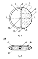
- fig. 1 presents the valve disc seen from the front with partial cross-section
- fig. 2 shows the cross-section of the disc of the throttling valve.
- Cover 1 is formed from a sheet of steel and cover 13 is formed in the shape of die stampings with recesses 2.
- the sleeve-enforcement unit 3 contains the spacer pipe 4, fixed in enforcement segments 5 an welded to join those enforcement segments with the spacer pipe.
- the spacer pipe, with the driver sleeve 6 and the centralizing sleeve 7 fixed at its ends, is placed between the covers 1, 13. Then all of them are pressed together and joined by welding. Further on, through aperture 11 in cover 13 the disc of the throttling valve is filled up with modified polymer concrete 10. After final hardness of the polymer concrete that fills up the inside of the disc is obtained, aperture 11 is welded up and the disc is ready to be installed in the throttling valve.
- the disc of the throttling valve contains two asymmetric metal covers 1, 13 and the sleeve-enforcement unit 3 fixed between them in the recesses 3.
- the unit is composed of the spacer pipe 4, to which enforcement segments are welded 5 and of the driver sleeve 6 and the centralizing sleeve 7.
- the covers 1, 13 are joined together; they are also joined with the driver sleeve 6 and the centralizing sleeve 7 by means of welds 12.
- Front surfaces 8, 9 of the sleeve are spherical.
- cover 13 there is a technical aperture 11.
- the disc of the throttling valve is filled with a mixture of quartz with resin.
Landscapes
- Engineering & Computer Science (AREA)
- General Engineering & Computer Science (AREA)
- Mechanical Engineering (AREA)
- Fluid-Damping Devices (AREA)
- Lift Valve (AREA)
Abstract
Description
- The invention concerns the method of manufacturing the throttling valve disc and the valve disc itself. The throttling valve is used as a cutting-off or regulating element in systems that carry gases or fluids.
- The method of manufacturing the valve disc is known from the Polish application description no
P-375177 - The method of manufacturing throttling valves of PAEK or its derivatives in the form of a stamping made on a injection moulding press in a feeding channel of a combustion engine is known from
DE 103 17 505 A1 . - The disc of the throttling valve, circular and convex, containing two identical covers inseparably joined at the edge is known from the description of the Polish invention registration no
P-375177 -
DE 103 17 505 A1 presents a blocking body for a flow-through channel, which has a throttling valve made of PAEK or its derivatives, two connected dished discs that make up an enclosed, empty space in the feeding channel of the combustion engine. - The manufacturing method of the throttling valve disc as described in the invention consists in plastic forming of a convex cover from a metal sheet, its cross-section resembling the letter "C", and forming another convex cover, which closes up the space limited with the other cover. The spacer pipe is placed in enforcement segments, each of which has two parallel sides joined at the ends and fixed to the spacer pipe. Then, in the manner already known, a spacer pipe is placed between the covers with the driver sleeve and the centralizing one, fixed at its ends, then they are pressed together and joined inseparably. The space of the throttling valve is filled with filler, preferably based on modified polymer concrete.
- The disc of the throttling valve, convex and circular in shape as in the invention, with two covers inseparably joined with the sleeve-enforcement unit containing the driver and the centralizing sleeves, fixed between the covers on a spacer pipe and filled with appropriate filler, is characterized by one cover in the cross-section of the "C" letter, while the other closes off the space limited by the first one. The spacer pipe is fixed on enforcement segments which have two parallel sides joined together at the ends and the pipe is joined to them inseparably.
- According to the invention the manufactured disc of the throttling valve has surface of its circular perimeter which constitutes a monolithic fragment of a cover of significant size and smoothness accuracy. This part of the disc surface which touches, when closed, the valve seal, ensures its tightness.
- The disc of the throttling valve according to the invention requires less welding, and the part of the disc surface that is in contact with the valve seal, when closed, does not require any additional working, which reduces manufacturing cost.
- An example of the invention performance is shown in the picture, where
fig. 1 presents the valve disc seen from the front with partial cross-section,fig. 2 shows the cross-section of the disc of the throttling valve. -
Cover 1 is formed from a sheet of steel andcover 13 is formed in the shape of die stampings with recesses 2. The sleeve-enforcement unit 3 contains the spacer pipe 4, fixed inenforcement segments 5 an welded to join those enforcement segments with the spacer pipe. The spacer pipe, with the driver sleeve 6 and the centralizingsleeve 7 fixed at its ends, is placed between thecovers aperture 11 incover 13 the disc of the throttling valve is filled up with modifiedpolymer concrete 10. After final hardness of the polymer concrete that fills up the inside of the disc is obtained,aperture 11 is welded up and the disc is ready to be installed in the throttling valve. - The disc of the throttling valve contains two asymmetric metal covers 1, 13 and the sleeve-enforcement unit 3 fixed between them in the recesses 3. The unit is composed of the spacer pipe 4, to which enforcement segments are welded 5 and of the
driver sleeve 6 and the centralizingsleeve 7. Thecovers driver sleeve 6 and the centralizingsleeve 7 by means ofwelds 12.Front surfaces 8, 9 of the sleeve are spherical. Incover 13 there is atechnical aperture 11. The disc of the throttling valve is filled with a mixture of quartz with resin.
Claims (2)
- The manufacturing method of the throttling valve disc, in which two convex covers are plastic-formed from metal sheets, with circular edges with recesses and the sleeve-enforcement unit placed between them, containing the spacer pipe with driver and centralizing sleeves fixed on its ends, with the covers pressed together to each other and to the sleeve-enforcement unit and joined inseparably, and all the space between the covers later filled with filler, is characterised by forming a cover (1) of the "C"-shaped cross-section and forming another cover (13) closing off the space limited with the cover (1), while the spacer pipe (4) is fixed in enforcement segments (5) which have two parallel sides joined together at the ends and then the spacer pipe (4) is inseparably joined to enforcement segments (5), then between the covers (1, 13) the spacer pipe is placed (4) with the driver sleeve (6) and the centralizing sleeve (7) fixed at its ends, all the elements are pressed together and joined inseparably and the empty space in the disc of the throttling valve is filled with filler (10), preferably based on modified polymer concrete.
- The throttling valve disc, circular and convex, with two covers inseparably joined together and inseparably joined to the sleeve-enforcement unit with the driver sleeve and the centralizing one fixed between the covers on the spacer pipe, while the space between the covers is filled with filler, is characterised by one cover (1) having a "C"-shaped cross-section, and the other cover (13) closing off the space limited with the cover (1), while the spacer pipe (4) is fixed in enforcement segments (5) which have two parallel sides joined together at the ends and is inseparably joined to them.
Applications Claiming Priority (1)
| Application Number | Priority Date | Filing Date | Title |
|---|---|---|---|
| PL381754A PL213221B3 (en) | 2007-02-13 | 2007-02-13 | The manner of production of choke valve disk and choke valve |
Publications (1)
| Publication Number | Publication Date |
|---|---|
| EP1959175A1 true EP1959175A1 (en) | 2008-08-20 |
Family
ID=39340950
Family Applications (1)
| Application Number | Title | Priority Date | Filing Date |
|---|---|---|---|
| EP07460029A Withdrawn EP1959175A1 (en) | 2007-02-13 | 2007-10-16 | Disc of butterfly valve and a method to manufacture |
Country Status (2)
| Country | Link |
|---|---|
| EP (1) | EP1959175A1 (en) |
| PL (1) | PL213221B3 (en) |
Citations (6)
| Publication number | Priority date | Publication date | Assignee | Title |
|---|---|---|---|---|
| DE1083611B (en) * | 1958-11-18 | 1960-06-15 | Voith Gmbh J M | Throttle valve in welded construction, especially for high pressure pipelines to water power plants |
| US4253641A (en) * | 1978-12-07 | 1981-03-03 | Vanryck Theodore H | Butterfly valve and perimeter seal |
| JPS61105373A (en) * | 1984-10-29 | 1986-05-23 | Toshiba Corp | Butterfly valve |
| JP2003340848A (en) * | 2002-05-28 | 2003-12-02 | Nippon Zeon Co Ltd | Method for producing norbornene-based resin molded article and norbornene-based resin molded article |
| DE10317505A1 (en) | 2003-04-16 | 2005-01-20 | Daimlerchrysler Ag | Switching device for a flow channel comprises a switching flap made of a polyaryl ether ketone, and provided with at least one rib and/or at least one shell-like arched surface |
| EP1731805A1 (en) | 2005-05-17 | 2006-12-13 | Wojciech Spalony | Disc of a butterfly valve and method to manufacture |
-
2007
- 2007-02-13 PL PL381754A patent/PL213221B3/en unknown
- 2007-10-16 EP EP07460029A patent/EP1959175A1/en not_active Withdrawn
Patent Citations (6)
| Publication number | Priority date | Publication date | Assignee | Title |
|---|---|---|---|---|
| DE1083611B (en) * | 1958-11-18 | 1960-06-15 | Voith Gmbh J M | Throttle valve in welded construction, especially for high pressure pipelines to water power plants |
| US4253641A (en) * | 1978-12-07 | 1981-03-03 | Vanryck Theodore H | Butterfly valve and perimeter seal |
| JPS61105373A (en) * | 1984-10-29 | 1986-05-23 | Toshiba Corp | Butterfly valve |
| JP2003340848A (en) * | 2002-05-28 | 2003-12-02 | Nippon Zeon Co Ltd | Method for producing norbornene-based resin molded article and norbornene-based resin molded article |
| DE10317505A1 (en) | 2003-04-16 | 2005-01-20 | Daimlerchrysler Ag | Switching device for a flow channel comprises a switching flap made of a polyaryl ether ketone, and provided with at least one rib and/or at least one shell-like arched surface |
| EP1731805A1 (en) | 2005-05-17 | 2006-12-13 | Wojciech Spalony | Disc of a butterfly valve and method to manufacture |
Also Published As
| Publication number | Publication date |
|---|---|
| PL213221B3 (en) | 2013-01-31 |
| PL381754A3 (en) | 2008-08-18 |
Similar Documents
| Publication | Publication Date | Title |
|---|---|---|
| US9995398B2 (en) | Double eccentric valve | |
| US9303774B2 (en) | Valve assembly | |
| CN103620190B (en) | For controlling the valving that the aerofluxus of internal combustion engine is flowed | |
| EP2066934B1 (en) | Metal seal with flexible insert | |
| US20140021397A1 (en) | Sealing element for a gate valve | |
| KR101930081B1 (en) | Ball valve seat seal | |
| JP5871432B2 (en) | Rotary valve seal member and rotary valve using the same | |
| CN104948757A (en) | Cage valve | |
| JP2010502912A5 (en) | Valve assembly | |
| WO2007034404A3 (en) | Magnatic microfluidic valve | |
| US7758017B2 (en) | Butterfly valves and construction thereof | |
| CN107208407A (en) | The component in tube section can be embedded into via press-fit | |
| CN101815890B (en) | Composite valve | |
| EP1959175A1 (en) | Disc of butterfly valve and a method to manufacture | |
| US8739833B2 (en) | Venting valve | |
| CN100482987C (en) | Seat ring for butterfly valve | |
| JP6289978B2 (en) | Check valve | |
| EP1783409A1 (en) | Low noise valve flap and valve comprising a low noise valve flap | |
| US3779512A (en) | Stamped-disc butterfly valve | |
| BR112017028465A2 (en) | valve with non-round closing member | |
| JP6289979B2 (en) | Check valve | |
| KR102661554B1 (en) | Plastic butterfly valve | |
| KR20030004009A (en) | Butterfly valve | |
| JPH05501001A (en) | diaphragm valve | |
| CN107002915A (en) | Connection kits with hydraulic connection elements |
Legal Events
| Date | Code | Title | Description |
|---|---|---|---|
| PUAI | Public reference made under article 153(3) epc to a published international application that has entered the european phase |
Free format text: ORIGINAL CODE: 0009012 |
|
| AK | Designated contracting states |
Kind code of ref document: A1 Designated state(s): AT BE BG CH CY CZ DE DK EE ES FI FR GB GR HU IE IS IT LI LT LU LV MC MT NL PL PT RO SE SI SK TR |
|
| AX | Request for extension of the european patent |
Extension state: AL BA HR MK RS |
|
| 17P | Request for examination filed |
Effective date: 20081007 |
|
| 17Q | First examination report despatched |
Effective date: 20081117 |
|
| AKX | Designation fees paid |
Designated state(s): AT BE BG CH CY CZ DE DK EE ES FI FR GB GR HU IE IS IT LI LT LU LV MC MT NL PL PT RO SE SI SK TR |
|
| RAP1 | Party data changed (applicant data changed or rights of an application transferred) |
Owner name: AFT SP. Z O.O |
|
| RIN1 | Information on inventor provided before grant (corrected) |
Inventor name: SPALONY WOJCIECH |
|
| STAA | Information on the status of an ep patent application or granted ep patent |
Free format text: STATUS: THE APPLICATION IS DEEMED TO BE WITHDRAWN |
|
| 18D | Application deemed to be withdrawn |
Effective date: 20130503 |