EP1959135B1 - A method for eliminating the impact of backlashes in the gearbox of a wind turbine - Google Patents
A method for eliminating the impact of backlashes in the gearbox of a wind turbine Download PDFInfo
- Publication number
- EP1959135B1 EP1959135B1 EP08001671.0A EP08001671A EP1959135B1 EP 1959135 B1 EP1959135 B1 EP 1959135B1 EP 08001671 A EP08001671 A EP 08001671A EP 1959135 B1 EP1959135 B1 EP 1959135B1
- Authority
- EP
- European Patent Office
- Prior art keywords
- wind turbine
- drive train
- generator
- grid
- dump load
- Prior art date
- Legal status (The legal status is an assumption and is not a legal conclusion. Google has not performed a legal analysis and makes no representation as to the accuracy of the status listed.)
- Not-in-force
Links
- 238000000034 method Methods 0.000 title claims description 27
- 238000010521 absorption reaction Methods 0.000 claims description 11
- 230000004913 activation Effects 0.000 claims description 6
- 230000008878 coupling Effects 0.000 claims description 4
- 238000010168 coupling process Methods 0.000 claims description 4
- 238000005859 coupling reaction Methods 0.000 claims description 4
- 230000001133 acceleration Effects 0.000 claims description 3
- 230000008859 change Effects 0.000 claims description 3
- 230000006698 induction Effects 0.000 claims description 2
- 230000001360 synchronised effect Effects 0.000 claims description 2
- 230000001052 transient effect Effects 0.000 claims description 2
- 238000004519 manufacturing process Methods 0.000 description 5
- 230000008901 benefit Effects 0.000 description 4
- 238000010586 diagram Methods 0.000 description 4
- 101150034273 SYS1 gene Proteins 0.000 description 2
- 230000002730 additional effect Effects 0.000 description 2
- 230000005284 excitation Effects 0.000 description 2
- 230000009467 reduction Effects 0.000 description 2
- 230000007704 transition Effects 0.000 description 2
- 230000002159 abnormal effect Effects 0.000 description 1
- 230000009471 action Effects 0.000 description 1
- 238000013016 damping Methods 0.000 description 1
- 230000009849 deactivation Effects 0.000 description 1
- 238000004146 energy storage Methods 0.000 description 1
- 239000000446 fuel Substances 0.000 description 1
- 230000020169 heat generation Effects 0.000 description 1
- 238000005461 lubrication Methods 0.000 description 1
- 230000004048 modification Effects 0.000 description 1
- 238000012986 modification Methods 0.000 description 1
- 230000000737 periodic effect Effects 0.000 description 1
Images
Classifications
-
- F—MECHANICAL ENGINEERING; LIGHTING; HEATING; WEAPONS; BLASTING
- F03—MACHINES OR ENGINES FOR LIQUIDS; WIND, SPRING, OR WEIGHT MOTORS; PRODUCING MECHANICAL POWER OR A REACTIVE PROPULSIVE THRUST, NOT OTHERWISE PROVIDED FOR
- F03D—WIND MOTORS
- F03D7/00—Controlling wind motors
- F03D7/02—Controlling wind motors the wind motors having rotation axis substantially parallel to the air flow entering the rotor
- F03D7/0244—Controlling wind motors the wind motors having rotation axis substantially parallel to the air flow entering the rotor for braking
- F03D7/0248—Controlling wind motors the wind motors having rotation axis substantially parallel to the air flow entering the rotor for braking by mechanical means acting on the power train
-
- F—MECHANICAL ENGINEERING; LIGHTING; HEATING; WEAPONS; BLASTING
- F03—MACHINES OR ENGINES FOR LIQUIDS; WIND, SPRING, OR WEIGHT MOTORS; PRODUCING MECHANICAL POWER OR A REACTIVE PROPULSIVE THRUST, NOT OTHERWISE PROVIDED FOR
- F03D—WIND MOTORS
- F03D15/00—Transmission of mechanical power
-
- F—MECHANICAL ENGINEERING; LIGHTING; HEATING; WEAPONS; BLASTING
- F03—MACHINES OR ENGINES FOR LIQUIDS; WIND, SPRING, OR WEIGHT MOTORS; PRODUCING MECHANICAL POWER OR A REACTIVE PROPULSIVE THRUST, NOT OTHERWISE PROVIDED FOR
- F03D—WIND MOTORS
- F03D15/00—Transmission of mechanical power
- F03D15/10—Transmission of mechanical power using gearing not limited to rotary motion, e.g. with oscillating or reciprocating members
-
- F—MECHANICAL ENGINEERING; LIGHTING; HEATING; WEAPONS; BLASTING
- F03—MACHINES OR ENGINES FOR LIQUIDS; WIND, SPRING, OR WEIGHT MOTORS; PRODUCING MECHANICAL POWER OR A REACTIVE PROPULSIVE THRUST, NOT OTHERWISE PROVIDED FOR
- F03D—WIND MOTORS
- F03D7/00—Controlling wind motors
- F03D7/02—Controlling wind motors the wind motors having rotation axis substantially parallel to the air flow entering the rotor
-
- F—MECHANICAL ENGINEERING; LIGHTING; HEATING; WEAPONS; BLASTING
- F03—MACHINES OR ENGINES FOR LIQUIDS; WIND, SPRING, OR WEIGHT MOTORS; PRODUCING MECHANICAL POWER OR A REACTIVE PROPULSIVE THRUST, NOT OTHERWISE PROVIDED FOR
- F03D—WIND MOTORS
- F03D7/00—Controlling wind motors
- F03D7/02—Controlling wind motors the wind motors having rotation axis substantially parallel to the air flow entering the rotor
- F03D7/04—Automatic control; Regulation
- F03D7/042—Automatic control; Regulation by means of an electrical or electronic controller
-
- F—MECHANICAL ENGINEERING; LIGHTING; HEATING; WEAPONS; BLASTING
- F03—MACHINES OR ENGINES FOR LIQUIDS; WIND, SPRING, OR WEIGHT MOTORS; PRODUCING MECHANICAL POWER OR A REACTIVE PROPULSIVE THRUST, NOT OTHERWISE PROVIDED FOR
- F03D—WIND MOTORS
- F03D9/00—Adaptations of wind motors for special use; Combinations of wind motors with apparatus driven thereby; Wind motors specially adapted for installation in particular locations
- F03D9/20—Wind motors characterised by the driven apparatus
- F03D9/25—Wind motors characterised by the driven apparatus the apparatus being an electrical generator
-
- F—MECHANICAL ENGINEERING; LIGHTING; HEATING; WEAPONS; BLASTING
- F03—MACHINES OR ENGINES FOR LIQUIDS; WIND, SPRING, OR WEIGHT MOTORS; PRODUCING MECHANICAL POWER OR A REACTIVE PROPULSIVE THRUST, NOT OTHERWISE PROVIDED FOR
- F03D—WIND MOTORS
- F03D9/00—Adaptations of wind motors for special use; Combinations of wind motors with apparatus driven thereby; Wind motors specially adapted for installation in particular locations
- F03D9/20—Wind motors characterised by the driven apparatus
- F03D9/25—Wind motors characterised by the driven apparatus the apparatus being an electrical generator
- F03D9/255—Wind motors characterised by the driven apparatus the apparatus being an electrical generator connected to electrical distribution networks; Arrangements therefor
-
- F—MECHANICAL ENGINEERING; LIGHTING; HEATING; WEAPONS; BLASTING
- F16—ENGINEERING ELEMENTS AND UNITS; GENERAL MEASURES FOR PRODUCING AND MAINTAINING EFFECTIVE FUNCTIONING OF MACHINES OR INSTALLATIONS; THERMAL INSULATION IN GENERAL
- F16H—GEARING
- F16H57/00—General details of gearing
- F16H57/12—Arrangements for adjusting or for taking-up backlash not provided for elsewhere
- F16H2057/123—Arrangements for adjusting or for taking-up backlash not provided for elsewhere using electric control means
-
- Y—GENERAL TAGGING OF NEW TECHNOLOGICAL DEVELOPMENTS; GENERAL TAGGING OF CROSS-SECTIONAL TECHNOLOGIES SPANNING OVER SEVERAL SECTIONS OF THE IPC; TECHNICAL SUBJECTS COVERED BY FORMER USPC CROSS-REFERENCE ART COLLECTIONS [XRACs] AND DIGESTS
- Y02—TECHNOLOGIES OR APPLICATIONS FOR MITIGATION OR ADAPTATION AGAINST CLIMATE CHANGE
- Y02E—REDUCTION OF GREENHOUSE GAS [GHG] EMISSIONS, RELATED TO ENERGY GENERATION, TRANSMISSION OR DISTRIBUTION
- Y02E10/00—Energy generation through renewable energy sources
- Y02E10/70—Wind energy
- Y02E10/72—Wind turbines with rotation axis in wind direction
Definitions
- the invention relates to a method for eliminating the impact of backlashes in the gearbox of a wind turbine and to a wind turbine having means for implementing such method.
- Wind turbine gearboxes need to have a certain gap between its components for several purposes such as avoid interference, wear, and excessive heat generation, ensure proper lubrication or compensate for manufacturing tolerances. Said gaps cause that at a load reversal the output shaft will turn a slight angle even though the input shaft is not rotating. The value of the shaft "turn angle at zero load” is called the rotational backlash of the gearbox.
- the drive train Due to the variations of rotor and generator torques, the drive train is excited dynamically producing a permanently varying pretension. In certain states the pretension of the drive train is completely released or even inversed. The inversion of the pretension produces backlashes which can amplify due to the excitations introduced by the varying rotor and generator torque.
- An object of the present invention is to provide a method for operating a wind turbine for eliminating the impact of backlashes in the gearbox according to claim 1 and a wind turbine according to claim 9.
- a method for operating a wind turbine comprising a drive train driving one or more electrical generators that supply power to an electric grid, the drive train including a rotor hub, to which one or more blades are attached, a main shaft, a gearbox and connecting shafts to said one or more electrical generators that, in events that can create a load inversion in the gearbox, a drive train dump load is activated for ensuring that the drive train torque has a constant direction, avoiding the impact of backlashes in the gearbox, said dump load consisting of power absorbed by one or several means chosen among means specifically dedicated to the absorption of said dump load and means present at the wind turbine for other purposes.
- gearbox do contain a planetary stage or more planetary stages it is advantageous to keep a constant direction of the tension, as the positioning of the sun wheel then gets normal operating conditions which improves the gearbox lifetime and allows optimized designs.
- gear stages in a gearbox such as a parallel shaft gear stage, especially the helical ones
- the advantage is not just the fatigue reduction of the teeth, but also the reduction in the variations of the axial forces put to the bearings, those axial forces are created by the torque changes in the helical stage.
- Another advantage of this method is that the acoustic emission will be less as the rattle from the presence of the backlash will no longer emit any sound.
- the dump load is activated in the event of the wind turbine start up avoiding load inversions in the drive train during this operation.
- the dump load is activated in the event of the disconnection of the wind turbine from the grid facilitating a smooth disconnection procedure.
- the dump load is activated in different events in which the operational state of the wind turbine is a transient state facilitating that the wind turbine may ride-through them improving the power production.
- Another object of the present invention is to provide a wind turbine for implementing the above-described method.
- a wind turbine comprising a drive train driving one or more electrical generators that supply power to an electric grid, the drive train including a rotor hub, to which one or more blades are attached, a main shaft, a gearbox and connecting shafts to said one or more electrical generators that also comprises power absorption means for generating a drive train dump load which is used for ensuring that the drive train torque has a constant direction, avoiding the impact of backlashes in the gearbox, said power absorption means being chosen among means specifically dedicated to the absorption of said dump load and means present at the wind turbine for other purposes.
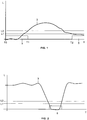
- FIG. 1 Time T in x-axis, Drive Train Torque L in y-axis shows a typical evolution of the load 3 in the gearbox of a wind turbine in two events that can cause difficulties with backlashes: a wind turbine start-up, occurring from time T0 to time T1, and a low wind situation, beginning in time T2.
- an adequate dump load 5 is partly or fully activated, depending on the type of the dump load being used, in both events.
- the dump load 5 is activated for loading the drive train at the generator side of the gearbox.
- the main shaft starts rotating it will be loaded to some extent by the dump load 5, the drive train will be aligned and there will be a well defined tension in it. Otherwise there will be torque shifts as shown in Fig. 1 .
- the generator When conditions are adequate the generator will start to deliver active electrical power to the grid, and the dump load 5 will still be activated to some extent.
- main shaft torque is above a predetermined torque level L2 the dump load 5 is partly or fully deactivated, depending on the type of dump load being used, and no dump load related loss in energy yield will occur.
- the main shaft torque may be below a certain level that may cause problems.
- the dump load 5 is partly or fully activated which ensures good tension and working conditions for the drive train and the gearbox.
- FIG. 2 shows a typical evolution of the load 3 in the gearbox of a wind turbine when the generator coupling state changes, i.e. from "star” to "delta” coupling or the opposite, an event that may cause torque shifts.
- the dump load 5 when the main shaft torque is below a predetermined torque level L1, the dump load 5 is partly or fully activated and when the main shaft torque is above a predetermined torque level L2 the dump load 5 is partly or fully deactivated, and no dump load related loss in energy yield will occur.
- the activation of a dump load when the main shaft torque is below a predetermined torque level L1 and, if required, the deactivation of a dump load when the main shaft torque is above a predetermined torque level L2 shall be done in any event that can cause load inversions in the drive train such as the following:
- the method according to this invention includes an additional action to the activation of a dump load.
- One of these events is a disconnection of the wind turbine at a wind speed higher than cut-out wind speed (sometimes called stop wind).
- the speed controller would normally bring the rotor to standstill and the blade pitch angle references will be set to 90 deg. Doing so the rotor will be left oscillating in direction and the activation of the chosen dump load may be insufficient for ensuring the drive train tension.
- the method according to this invention includes also an action for keeping the rotor speed above a predetermined value, for example setting the pitch angle reference to less than 90 deg.
- the method according to this invention includes an additional action to the activation of a dump load is a shift from "star" to "delta", or the opposite, generator connection to the grid.
- the method according to this invention includes the acceleration of the drive train as a way to ensure the tension of the drive train. So just before torque is effectively zero, some acceleration of the drive train is ensured by the speed controller and after a short instant - seconds - the shift in generator connection must be carried out and the speed controller can again act normally.
- Suitable dump loads for any type of wind turbine are the following:
- Suitable dump loads for any type of wind turbine in grid connected state are the following:
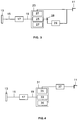
- FIGS 3 and 4 shows schematically two types of wind turbine widely used these days: a wind turbine with doubly feed converter and a wind turbine with full converter.
- the wind turbine comprises a drive train driving an electrical generator that supplies power to an electric grid 11 through a power electronics unit, the drive train including a rotor hub 13, to which one or more blades are attached, a main shaft 15, a gearbox 17 and a connecting shaft 19 to the electrical generator.
- the invention is also applicable to other types of wind turbines, particularly to wind turbines having two or more electrical generators.
- Figure 3 shows a wind turbine having a wound-rotor induction generator 23, with rotor 25 and stator 27 which is connected to the grid 11 through a IGBT-based and PWM electronic control converter 29 through sliprings 28.
- a suitable dump load for this type of wind turbine in grid connected state is power delivered to the grid.
- Another suitable dump load for this type of wind turbine in grid connected state is heat energy from generator 23 losses produced by presence of added reactive current in the generator 23.
- Figure 4 shows a wind turbine having a synchronous generator ex. a permanent magnet generator 31 with rotor 33 and stator 35 which is connected to the grid 11 through a full converter unit 37.
- a suitable dump load for this type of wind turbine in grid connected state is power delivered to the grid.
- Another suitable dump load for this type of wind turbine in grid connected state is heat energy from generator 31 losses produced by presence of added reactive current in the generator 31. These losses may be produced by means of a control of the converter 37 modules setting that one half of the converter modules (module 1, 2 and 3) gets an additional reactive power reference of Qref.sys1, and the rest (module 4, 5 and 6) get an additional reactive power reference of -Qref.sys1, so the overall influence towards the total reactive production is unchanged from the normal performance, but the heat loss in the generator is changed radically. This will work just as a dump load without any extra components, but through some change in the generator control software. Further it will react very fast - a few ms - and hence also be interesting for dynamic damping purposes in the drive train.
- Another suitable dump load for this type of wind turbine in grid disconnected state is heat energy from generator 31 dissipated in a resistor that could be also used as a dump load to absorb generator production during grid faults.
Landscapes
- Engineering & Computer Science (AREA)
- Life Sciences & Earth Sciences (AREA)
- Sustainable Development (AREA)
- Sustainable Energy (AREA)
- Chemical & Material Sciences (AREA)
- Combustion & Propulsion (AREA)
- Mechanical Engineering (AREA)
- General Engineering & Computer Science (AREA)
- Power Engineering (AREA)
- Wind Motors (AREA)
- Control Of Eletrric Generators (AREA)
Description
- The invention relates to a method for eliminating the impact of backlashes in the gearbox of a wind turbine and to a wind turbine having means for implementing such method.
- Wind turbine gearboxes need to have a certain gap between its components for several purposes such as avoid interference, wear, and excessive heat generation, ensure proper lubrication or compensate for manufacturing tolerances. Said gaps cause that at a load reversal the output shaft will turn a slight angle even though the input shaft is not rotating. The value of the shaft "turn angle at zero load" is called the rotational backlash of the gearbox.
- If the main shaft torque in the gearbox is zero, then the forces acting in the gear mesh will be approximately zero. Then there will be no tension of the drive train and some backlash will be present.
- If the main shaft torque in the gearbox increase larger than approximately zero then the forces acting in the gear mesh will act in only one direction and the drive train will be aligned and tension will increase.
- If the main shaft torque in the gearbox decrease below approximately zero then the forces acting in the gear mesh will act in only one direction, but now in an opposite direction and the drive train will be aligned and tension will increase.
- In wind turbines it is known that the dynamic impacts induced by periodic load inversions, i.e. backlash fenomena, propagate through the drive train and can be amplified due to the excitations introduced by rotor and generator torque variations so that they may cause the failure of the wind turbine drive train.
- Due to the variations of rotor and generator torques, the drive train is excited dynamically producing a permanently varying pretension. In certain states the pretension of the drive train is completely released or even inversed. The inversion of the pretension produces backlashes which can amplify due to the excitations introduced by the varying rotor and generator torque.
- Another drawback of backlashes is that they are an important source of noise.
- To the applicant knowledge it is not known prior art specifically addressed to overcome the difficulties with backlashes in wind turbines. There is indeed prior art teaching the use of generator torque control means and pitch control means for reducing the drive train loads in normal operational states and also prior art teaching the use of torque limiting devices in special wind situations such as in the event of gusts, but it is not known prior art focused in avoiding idling situations where the torque is random and shifting in direction with different unwanted potential consequences, including the production of noise. Examples of relevant prior art are given by patent publications
DE 10 2004 007461 A1 (2005-09-01),FR 1 433 859 A US 2005/116476 A1 (2005-06-02). - An object of the present invention is to provide a method for operating a wind turbine for eliminating the impact of backlashes in the gearbox according to claim 1 and a wind turbine according to claim 9.
- This and other objects are met by providing a method for operating a wind turbine comprising a drive train driving one or more electrical generators that supply power to an electric grid, the drive train including a rotor hub, to which one or more blades are attached, a main shaft, a gearbox and connecting shafts to said one or more electrical generators that, in events that can create a load inversion in the gearbox, a drive train dump load is activated for ensuring that the drive train torque has a constant direction, avoiding the impact of backlashes in the gearbox, said dump load consisting of power absorbed by one or several means chosen among means specifically dedicated to the absorption of said dump load and means present at the wind turbine for other purposes.
- One advantage of this method is that if the gearbox do contain a planetary stage or more planetary stages it is advantageous to keep a constant direction of the tension, as the positioning of the sun wheel then gets normal operating conditions which improves the gearbox lifetime and allows optimized designs. For other types of gear stages in a gearbox, such as a parallel shaft gear stage, especially the helical ones, the advantage is not just the fatigue reduction of the teeth, but also the reduction in the variations of the axial forces put to the bearings, those axial forces are created by the torque changes in the helical stage.
- Another advantage of this method is that the acoustic emission will be less as the rattle from the presence of the backlash will no longer emit any sound.
- In an embodiment of this invention the dump load is activated in the event of the wind turbine start up avoiding load inversions in the drive train during this operation.
- In another embodiment of this invention the dump load is activated in the event of the disconnection of the wind turbine from the grid facilitating a smooth disconnection procedure.
- In another embodiments of this invention, the dump load is activated in different events in which the operational state of the wind turbine is a transient state facilitating that the wind turbine may ride-through them improving the power production.
- Another object of the present invention is to provide a wind turbine for implementing the above-described method.
- This and other objects are met by providing a wind turbine comprising a drive train driving one or more electrical generators that supply power to an electric grid, the drive train including a rotor hub, to which one or more blades are attached, a main shaft, a gearbox and connecting shafts to said one or more electrical generators that also comprises power absorption means for generating a drive train dump load which is used for ensuring that the drive train torque has a constant direction, avoiding the impact of backlashes in the gearbox, said power absorption means being chosen among means specifically dedicated to the absorption of said dump load and means present at the wind turbine for other purposes.
- Other features and advantages of the present invention will be understood from the following detailed description of illustrative and by no means limiting embodiments of its object in relation with the enclosed drawings.
-
-
Figure 1 is a schematic diagram illustrating the method of this invention in two events: the wind turbine start up and a low wind situation. -
Figure 2 is a schematic diagram illustrating the method of this invention in the event of a shift from star to delta, or the opposite, generator connection to the grid. -
Figure 3 is a block diagram of a wind turbine with a doubly feed converter for implementing the method of this invention. -
Figure 4 is a block diagram of a wind turbine with a full converter for implementing the method of this invention. -
Figure 1 (Time T in x-axis, Drive Train Torque L in y-axis) shows a typical evolution of theload 3 in the gearbox of a wind turbine in two events that can cause difficulties with backlashes: a wind turbine start-up, occurring from time T0 to time T1, and a low wind situation, beginning in time T2. - According to this invention an
adequate dump load 5 is partly or fully activated, depending on the type of the dump load being used, in both events. - At start-up the
dump load 5 is activated for loading the drive train at the generator side of the gearbox. When the main shaft starts rotating it will be loaded to some extent by thedump load 5, the drive train will be aligned and there will be a well defined tension in it. Otherwise there will be torque shifts as shown inFig. 1 . - When conditions are adequate the generator will start to deliver active electrical power to the grid, and the
dump load 5 will still be activated to some extent. When main shaft torque is above a predetermined torque level L2 thedump load 5 is partly or fully deactivated, depending on the type of dump load being used, and no dump load related loss in energy yield will occur. - In a low wind situation, the main shaft torque may be below a certain level that may cause problems. In such event, when the main shaft torque is below a predetermined torque level L1, the
dump load 5 is partly or fully activated which ensures good tension and working conditions for the drive train and the gearbox. -
Figure 2 (Time T in x-axis, Drive Train Torque L in y-axis) shows a typical evolution of theload 3 in the gearbox of a wind turbine when the generator coupling state changes, i.e. from "star" to "delta" coupling or the opposite, an event that may cause torque shifts. In this event, according to this invention, when the main shaft torque is below a predetermined torque level L1, thedump load 5 is partly or fully activated and when the main shaft torque is above a predetermined torque level L2 thedump load 5 is partly or fully deactivated, and no dump load related loss in energy yield will occur. - According to this invention, the activation of a dump load when the main shaft torque is below a predetermined torque level L1 and, if required, the deactivation of a dump load when the main shaft torque is above a predetermined torque level L2 shall be done in any event that can cause load inversions in the drive train such as the following:
- Wind turbine fault situations where a transition from a normal operation state into a fault state is needed.
- Grid fault situations where a transition from a normal operation state into a fault state is needed.
- Grid abnormal conditions such as a "ride-through" sequence where the wind turbine shall continue to deliver power to the grid when the grid fault has been cleared.
- There are events in which the method according to this invention includes an additional action to the activation of a dump load. One of these events is a disconnection of the wind turbine at a wind speed higher than cut-out wind speed (sometimes called stop wind). In this case, the speed controller would normally bring the rotor to standstill and the blade pitch angle references will be set to 90 deg. Doing so the rotor will be left oscillating in direction and the activation of the chosen dump load may be insufficient for ensuring the drive train tension. So, in this case, the method according to this invention includes also an action for keeping the rotor speed above a predetermined value, for example setting the pitch angle reference to less than 90 deg.
- Another event in which the method according to this invention includes an additional action to the activation of a dump load is a shift from "star" to "delta", or the opposite, generator connection to the grid. In this event the method according to this invention includes the acceleration of the drive train as a way to ensure the tension of the drive train. So just before torque is effectively zero, some acceleration of the drive train is ensured by the speed controller and after a short instant - seconds - the shift in generator connection must be carried out and the speed controller can again act normally.
- As it has been said, there are many types of dump loads for implementing the method according to this invention.
- Suitable dump loads for any type of wind turbine are the following:
- Heat from friction in the existing brake.
- Heat from shaft friction ex. from a shaft mounted fan
- Power absorbed and transferred to a energy storage of a kind with the purpose to be recaptured later, using means such as a battery and a battery charger, a flywheel and an electrical machine, a tank and a pump and some pressure tanks and a fuel cell system.
- Suitable dump loads for any type of wind turbine in grid connected state are the following:
- Power delivered to the grid.
- Heat energy from loss in resistor connected to generator or converter.
- Heat energy from extra activation of the loss in wind turbine auxiliary components as pumps and fans.
- Heat energy in generator caused by extra generator losses due to circulation of extra reactive current.
-
Figures 3 and 4 shows schematically two types of wind turbine widely used these days: a wind turbine with doubly feed converter and a wind turbine with full converter. In both cases the wind turbine comprises a drive train driving an electrical generator that supplies power to anelectric grid 11 through a power electronics unit, the drive train including arotor hub 13, to which one or more blades are attached, amain shaft 15, agearbox 17 and a connectingshaft 19 to the electrical generator. - The invention is also applicable to other types of wind turbines, particularly to wind turbines having two or more electrical generators.
-
Figure 3 shows a wind turbine having a wound-rotor induction generator 23, withrotor 25 andstator 27 which is connected to thegrid 11 through a IGBT-based and PWMelectronic control converter 29 throughsliprings 28. - A suitable dump load for this type of wind turbine in grid connected state is power delivered to the grid.
- Another suitable dump load for this type of wind turbine in grid connected state is heat energy from
generator 23 losses produced by presence of added reactive current in thegenerator 23. - Another suitable dump load for this type of wind turbine in grid disconnected state for the event of a change of the
generator 23 coupling state from "star" to "delta" or the opposite is in parallel to the active power deloading of the generator to let the speed of the shaft accelerate which will make the torque in the gearbox having a constant positive value caused by the torque it takes to spin up the generator inertia. -
Figure 4 shows a wind turbine having a synchronous generator ex. apermanent magnet generator 31 withrotor 33 andstator 35 which is connected to thegrid 11 through afull converter unit 37. - A suitable dump load for this type of wind turbine in grid connected state is power delivered to the grid.
- Another suitable dump load for this type of wind turbine in grid connected state is heat energy from
generator 31 losses produced by presence of added reactive current in thegenerator 31. These losses may be produced by means of a control of theconverter 37 modules setting that one half of the converter modules (module 1, 2 and 3) gets an additional reactive power reference of Qref.sys1, and the rest (module 4, 5 and 6) get an additional reactive power reference of -Qref.sys1, so the overall influence towards the total reactive production is unchanged from the normal performance, but the heat loss in the generator is changed radically. This will work just as a dump load without any extra components, but through some change in the generator control software. Further it will react very fast - a few ms - and hence also be interesting for dynamic damping purposes in the drive train. - Another suitable dump load for this type of wind turbine in grid disconnected state is heat energy from
generator 31 dissipated in a resistor that could be also used as a dump load to absorb generator production during grid faults. - Although the present invention has been fully described in connection with preferred embodiments, it is evident that modifications may be introduced within the scope thereof, not considering this as limited by these embodiments, but by the contents of the following claims.
Claims (12)
- Method for operating a wind turbine comprising a drive train driving one or more electrical generators (23, 31) that supply power to an electric grid (11), the drive train including a rotor hub (13), to which one or more blades are attached, a main shaft (15), a gearbox (17) and connecting shafts (19) to said one or more electrical generators (23, 31), wherein in events that can create a load inversion in the gearbox (17), a drive train dump load (5) is activated by a controller_for ensuring that the drive train torque has a constant direction, avoiding the backlashes in the gearbox (17), said dump load (5) consisting of power absorbed by one or several means chosen among means specifically dedicated to the absorption of said dump load (5) and means present at the wind turbine for other purposes, and characterized in that when the drive train torque is above a predetermined value (L2), the drive train dump (5) load is deactivated by the controller.
- Method for operating a wind turbine according to claim 1, characterized in that one of said events is the wind turbine start up and in that said dump load (5) is activated at the beginning of the start up.
- Method for operating a wind turbine according to claim 1, characterized in that one of said events is a low wind situation and in that said dump load (5) is activated when the drive train torque is below a predetermined value (L1).
- Method for operating a wind turbine according to claim 1, characterized in that one of said events is a change of the generator coupling state and in that said dump load (5) is activated when the drive train torque is below a predetermined value (L1).
- Method for operating a wind turbine according to claim 4, characterized in that, an acceleration of the rotor (13) is carried out just before the drive train torque value is zero.
- Method for operating a wind turbine according to claim 1, characterized in that one of said events is any event in which the operational state of the wind turbine is a transient state due to a grid fault or a wind turbine fault and in that said dump load (5) is activated when the drive train torque is below a predetermined value (L1).
- Method for operating a wind turbine according to claim 1, characterized in that one of said events is the generator (23, 31) disconnection from the grid (11) and in that said dump load (5) is activated when the drive train torque is below a predetermined value (L1).
- Method for operating a wind turbine according to claim 7, characterized in that in the event of a disconnection from the grid (11) at a high wind speed in addition to the activation of the dump load (5), the rotor (13) speed is kept above a predetermined value R1.
- Wind turbine for implementing a method according to any of claims 1-8, comprising a drive train driving one or more electrical generators (23, 31) that supply power to an electric grid (11), the drive train including a rotor hub (13), to which one or more blades are attached, a main shaft (15), a gearbox (17) and connecting shafts (19) to said one or more electrical generators (23, 31), power absorption means for generating a drive train dump load (5) activated by a controller which is used for ensuring that the drive train torque has a constant direction, avoiding the impact of backlashes in the gearbox, said power absorption means being chosen among means specifically dedicated to the absorption of said dump load (5) and means present at the wind turbine for other purposes, characterized in that the controller is arranged to deactivate the drive train dump load (5) when the drive train torque is above a predetermined value (L2).
- Wind turbine according to claim 9, characterized in that said power absorption means include one or more of the following:- any means suitable for transferring said power to a storage device;- the wind turbine brake, wind turbine pumps and wind turbine fans;
- Wind turbine according to any of claims 9-10, characterized in that said one or more electric generators are wound-rotor induction generators (23) which are connected to the grid through a IGBT-based and PWM electronic control converter (29) and in that said power absorption means also include one or more of the following:- a generator (23) configuration producing additional power when the generator (23) is connected to the grid (11);- a resistor connected to the converter (29) or to the generator (23);- a parallel circuit connected to the generator (23), when the generator (23) is not connected to the grid (11).
- Wind turbine according to any of claims 9-10, characterized in that said one or more electric generators are synchronous generators (31) connected to the grid through a full converter unit (37) and in that said power absorption means also include one or more of the following:- a converter (37) configuration producing additional power or additional generator (31) losses when the generator (31) is connected to the grid (11).- a resistor connected to the generator (31), when the generator (31) is not connected to the grid.
Applications Claiming Priority (1)
| Application Number | Priority Date | Filing Date | Title |
|---|---|---|---|
| ES200700248A ES2341820B1 (en) | 2007-01-31 | 2007-01-31 | A METHOD TO ELIMINATE THE IMPACT OF BACKWARDS ON THE MULTIPLIER OF AN AEROGENERATOR. |
Publications (3)
| Publication Number | Publication Date |
|---|---|
| EP1959135A2 EP1959135A2 (en) | 2008-08-20 |
| EP1959135A3 EP1959135A3 (en) | 2014-04-23 |
| EP1959135B1 true EP1959135B1 (en) | 2020-03-25 |
Family
ID=39577326
Family Applications (1)
| Application Number | Title | Priority Date | Filing Date |
|---|---|---|---|
| EP08001671.0A Not-in-force EP1959135B1 (en) | 2007-01-31 | 2008-01-30 | A method for eliminating the impact of backlashes in the gearbox of a wind turbine |
Country Status (4)
| Country | Link |
|---|---|
| US (1) | US7605488B2 (en) |
| EP (1) | EP1959135B1 (en) |
| CN (1) | CN101240776B (en) |
| ES (2) | ES2341820B1 (en) |
Families Citing this family (16)
| Publication number | Priority date | Publication date | Assignee | Title |
|---|---|---|---|---|
| KR100774309B1 (en) * | 2006-11-28 | 2007-11-08 | 한국해양연구원 | Helical Turbine Power Generation System |
| US8573937B2 (en) | 2008-11-21 | 2013-11-05 | Xzeres Corp. | System for providing dynamic pitch control in a wind turbine |
| US8512199B2 (en) | 2010-07-26 | 2013-08-20 | Rethink Robotics, Inc. | Minimizing backlash utilizing series elastic elements |
| ES2396504B1 (en) * | 2010-10-29 | 2014-01-02 | Gamesa Innovation & Technology, S.L. | AEROGENERATOR WITH ACTIVE CONTROL OF THE PASSENGER ANGLE DURING AN EMPTY STARTING SITUATION. |
| US8686680B2 (en) | 2011-06-13 | 2014-04-01 | Rethink Robotics, Inc. | Dual-motor series elastic actuator |
| WO2013083139A2 (en) | 2011-12-08 | 2013-06-13 | Vestas Wind Systems A/S | Method and system for controlled shutdown of wind turbines |
| US9409298B2 (en) | 2012-04-13 | 2016-08-09 | Rethink Robotics, Inc. | Flexure elements for series elastic actuators and related methods |
| CN105556116B (en) | 2013-09-05 | 2019-04-16 | 维斯塔斯风力系统集团公司 | Speed management of wind turbines when switching electrical configurations |
| DK3063851T3 (en) | 2013-10-31 | 2022-02-28 | Gen Electric | SYSTEM AND METHOD FOR MANAGING WIND POWER GENERATION SYSTEMS |
| WO2015074664A1 (en) * | 2013-11-21 | 2015-05-28 | Vestas Wind Systems A/S | Rotor blade control for high winds |
| EP3118452B1 (en) * | 2014-10-16 | 2021-02-24 | Ingeteam Power Technology, S.A. | Kit for a wind station, and method |
| CN105826917B (en) | 2015-01-04 | 2019-10-08 | 通用电气公司 | Power conversion system and its control method and wind turbine electricity generating system |
| PT3157161T (en) * | 2015-10-12 | 2019-06-04 | Siemens Ag | METHOD TO CONTROL A WIND POWER INSTALLATION |
| DE102019100941B4 (en) | 2019-01-15 | 2021-08-26 | Lenze Se (Societas Europaea) | Method for monitoring a transmission driven by an electric motor |
| WO2024094263A1 (en) * | 2022-11-02 | 2024-05-10 | Vestas Wind Systems A/S | Operating wind turbine at reduced power output |
| IT202300021060A1 (en) * | 2023-10-10 | 2025-04-10 | Ge Avio Srl | LUBRICATION SYSTEM FOR A TURBINE ENGINE |
Family Cites Families (18)
| Publication number | Priority date | Publication date | Assignee | Title |
|---|---|---|---|---|
| GB1109166A (en) * | 1964-07-07 | 1968-04-10 | Fairey Eng | Improvements relating to reversible drive transmission means incorporating a speed-reduction gear train |
| FR1433859A (en) * | 1965-05-13 | 1966-04-01 | Philips Nv | Backlash-free drive mechanism |
| US4511807A (en) * | 1982-04-20 | 1985-04-16 | Northern Engineering Industries Plc | Electrical generator control system |
| US6574535B1 (en) * | 2000-05-31 | 2003-06-03 | General Motors Corporation | Apparatus and method for active driveline damping with clunk control |
| AUPR418901A0 (en) * | 2001-04-04 | 2001-05-03 | Applidyne Pty Ltd | Control system for cogeneration unit |
| EP1296441B1 (en) * | 2001-09-25 | 2006-08-16 | ABB Schweiz AG | Power generating arrangement |
| AU2003206633B2 (en) * | 2002-01-29 | 2006-11-02 | Vestas Wind Systems A/S | Circuit to be used in a wind power plant |
| US7431676B2 (en) * | 2002-11-25 | 2008-10-07 | Delbert Tesar | Self-contained rotary actuator |
| US7081062B2 (en) * | 2002-11-25 | 2006-07-25 | Delbert Tesar | Standardized rotary actuator |
| DE10361443B4 (en) * | 2003-12-23 | 2005-11-10 | Voith Turbo Gmbh & Co. Kg | Control for a wind turbine with hydrodynamic transmission |
| DE102004007461A1 (en) * | 2004-02-13 | 2005-09-01 | Helgers Finanzberatung Gmbh | Method for operating a wind turbine, and accordingly configured wind turbine |
| DE102004033680B4 (en) * | 2004-07-09 | 2009-03-12 | Wobben, Aloys, Dipl.-Ing. | load resistance |
| US20070100506A1 (en) * | 2005-10-31 | 2007-05-03 | Ralph Teichmann | System and method for controlling power flow of electric power generation system |
| US7276807B2 (en) * | 2006-01-19 | 2007-10-02 | General Electric Company | Wind turbine dump load system and method |
| US7352075B2 (en) * | 2006-03-06 | 2008-04-01 | General Electric Company | Methods and apparatus for controlling rotational speed of a rotor |
| US7476987B2 (en) * | 2006-04-25 | 2009-01-13 | The University Of New Brunswick | Stand-alone wind turbine system, apparatus, and method suitable for operating the same |
| US7394166B2 (en) * | 2006-10-04 | 2008-07-01 | General Electric Company | Method, apparatus and computer program product for wind turbine start-up and operation without grid power |
| ES2354135T3 (en) * | 2007-04-30 | 2011-03-10 | Vestas Wind Systems A/S | METHOD FOR OPERATING A WIND TURBINE WITH STEP CONTROL. |
-
2007
- 2007-01-31 ES ES200700248A patent/ES2341820B1/en not_active Expired - Fee Related
-
2008
- 2008-01-30 CN CN2008100002764A patent/CN101240776B/en not_active Expired - Fee Related
- 2008-01-30 ES ES08001671T patent/ES2801003T3/en active Active
- 2008-01-30 US US12/011,995 patent/US7605488B2/en active Active
- 2008-01-30 EP EP08001671.0A patent/EP1959135B1/en not_active Not-in-force
Non-Patent Citations (1)
| Title |
|---|
| None * |
Also Published As
| Publication number | Publication date |
|---|---|
| CN101240776A (en) | 2008-08-13 |
| EP1959135A3 (en) | 2014-04-23 |
| ES2341820A1 (en) | 2010-06-28 |
| CN101240776B (en) | 2012-05-09 |
| ES2341820B1 (en) | 2011-05-13 |
| ES2801003T3 (en) | 2021-01-07 |
| US20080179886A1 (en) | 2008-07-31 |
| US7605488B2 (en) | 2009-10-20 |
| EP1959135A2 (en) | 2008-08-20 |
Similar Documents
| Publication | Publication Date | Title |
|---|---|---|
| US7605488B2 (en) | Method for eliminating the impact of backlashes in the gearbox of a wind turbine | |
| CA2762167C (en) | Power generation system and method for assembling the same | |
| US8203229B2 (en) | Auxiliary drive/brake system for a wind turbine | |
| CN101050753B (en) | Control system for wind turbine with hydrodynamic transmission | |
| EP2461030A2 (en) | Drivetrain for generator in wind turbine | |
| US8147183B2 (en) | Drivetrain for generator in wind turbine | |
| WO2014013408A4 (en) | A dual-structured electric drive and power system for hybrid vehicles | |
| EP2917570A1 (en) | Wind turbine yaw control systems | |
| CA3086465A1 (en) | Windmill electrical power system and torque enhanced transmission | |
| WO2013091669A1 (en) | A turbo compound transmission and a method for controlling a turbo compound transmission | |
| CN103986278A (en) | Different connection motor | |
| CN106194583A (en) | A kind of change oar electric supply installation and wind power generating set | |
| US9447777B2 (en) | Continuous-flow power installation | |
| CA3202437A1 (en) | Method for controlling a ramp rate of a wind park with a plurality of wind turbines and wind park | |
| JP7563404B2 (en) | Wind power generation equipment | |
| KR102871024B1 (en) | Hybrid propulsion chain for aircraft including auxiliary mechanical drive system | |
| US9550412B2 (en) | Power generation system and method for assembling the same | |
| JP2023539804A (en) | Drives for mechanical drive equipment | |
| EP3242998A1 (en) | Power generation system and method for assembling the same | |
| JP7490136B2 (en) | Method for operating a train system for a mechanically driven device - Patents.com | |
| TWI714375B (en) | System and method for providing dynamic force | |
| CN116335879A (en) | Wind turbine speed control device, wind turbine and control method thereof | |
| JP7617275B2 (en) | Wind turbine rotation acceleration system | |
| US20090049941A1 (en) | Damping motor and control approach for mitigating torsional backlash, damping critical geartrain speeds, and providing improved torque control in mechanical gears | |
| CN121738825A (en) | Double wind wheel single gear box driving chain driving system and double wind wheel wind driven generator |
Legal Events
| Date | Code | Title | Description |
|---|---|---|---|
| PUAI | Public reference made under article 153(3) epc to a published international application that has entered the european phase |
Free format text: ORIGINAL CODE: 0009012 |
|
| AK | Designated contracting states |
Kind code of ref document: A2 Designated state(s): AT BE BG CH CY CZ DE DK EE ES FI FR GB GR HR HU IE IS IT LI LT LU LV MC MT NL NO PL PT RO SE SI SK TR |
|
| AX | Request for extension of the european patent |
Extension state: AL BA MK RS |
|
| PUAL | Search report despatched |
Free format text: ORIGINAL CODE: 0009013 |
|
| AK | Designated contracting states |
Kind code of ref document: A3 Designated state(s): AT BE BG CH CY CZ DE DK EE ES FI FR GB GR HR HU IE IS IT LI LT LU LV MC MT NL NO PL PT RO SE SI SK TR |
|
| AX | Request for extension of the european patent |
Extension state: AL BA MK RS |
|
| RIC1 | Information provided on ipc code assigned before grant |
Ipc: F03D 7/04 20060101ALI20140317BHEP Ipc: F03D 9/00 20060101ALI20140317BHEP Ipc: F03D 11/02 20060101ALI20140317BHEP Ipc: F03D 7/02 20060101AFI20140317BHEP Ipc: F16H 57/12 20060101ALI20140317BHEP |
|
| RAP1 | Party data changed (applicant data changed or rights of an application transferred) |
Owner name: GAMESA INNOVATION & TECHNOLOGY, S.L. |
|
| 17P | Request for examination filed |
Effective date: 20140915 |
|
| RBV | Designated contracting states (corrected) |
Designated state(s): AT BE BG CH CY CZ DE DK EE ES FI FR GB GR HR HU IE IS IT LI LT LU LV MC MT NL NO PL PT RO SE SI SK TR |
|
| AKX | Designation fees paid |
Designated state(s): AT BE BG CH CY LI |
|
| AXX | Extension fees paid |
Extension state: RS Extension state: MK Extension state: BA Extension state: AL |
|
| REG | Reference to a national code |
Ref country code: DE Ref legal event code: R108 |
|
| REG | Reference to a national code |
Ref country code: DE Ref legal event code: R108 Effective date: 20150106 |
|
| RBV | Designated contracting states (corrected) |
Designated state(s): AT BE BG CH CY CZ DE DK EE ES FI FR GB GR HR HU IE IS IT LI LT LU LV MC MT NL NO PL PT RO SE SI SK TR |
|
| RAP1 | Party data changed (applicant data changed or rights of an application transferred) |
Owner name: SIEMENS GAMESA RENEWABLE ENERGY INNOVATION & TECHN |
|
| GRAP | Despatch of communication of intention to grant a patent |
Free format text: ORIGINAL CODE: EPIDOSNIGR1 |
|
| STAA | Information on the status of an ep patent application or granted ep patent |
Free format text: STATUS: GRANT OF PATENT IS INTENDED |
|
| INTG | Intention to grant announced |
Effective date: 20191104 |
|
| RIC1 | Information provided on ipc code assigned before grant |
Ipc: F03D 7/04 20060101ALI20191018BHEP Ipc: F03D 15/00 20160101ALI20191018BHEP Ipc: F03D 9/25 20160101ALI20191018BHEP Ipc: F03D 7/02 20060101AFI20191018BHEP Ipc: F03D 9/00 20160101ALI20191018BHEP Ipc: F16H 57/12 20060101ALI20191018BHEP |
|
| GRAS | Grant fee paid |
Free format text: ORIGINAL CODE: EPIDOSNIGR3 |
|
| GRAA | (expected) grant |
Free format text: ORIGINAL CODE: 0009210 |
|
| STAA | Information on the status of an ep patent application or granted ep patent |
Free format text: STATUS: THE PATENT HAS BEEN GRANTED |
|
| AK | Designated contracting states |
Kind code of ref document: B1 Designated state(s): AT BE BG CH CY CZ DE DK EE ES FI FR GB GR HR HU IE IS IT LI LT LU LV MC MT NL NO PL PT RO SE SI SK TR |
|
| REG | Reference to a national code |
Ref country code: GB Ref legal event code: FG4D |
|
| REG | Reference to a national code |
Ref country code: AT Ref legal event code: REF Ref document number: 1248837 Country of ref document: AT Kind code of ref document: T Effective date: 20200415 Ref country code: IE Ref legal event code: FG4D |
|
| REG | Reference to a national code |
Ref country code: DE Ref legal event code: R096 Ref document number: 602008062369 Country of ref document: DE |
|
| PG25 | Lapsed in a contracting state [announced via postgrant information from national office to epo] |
Ref country code: FI Free format text: LAPSE BECAUSE OF FAILURE TO SUBMIT A TRANSLATION OF THE DESCRIPTION OR TO PAY THE FEE WITHIN THE PRESCRIBED TIME-LIMIT Effective date: 20200325 Ref country code: NO Free format text: LAPSE BECAUSE OF FAILURE TO SUBMIT A TRANSLATION OF THE DESCRIPTION OR TO PAY THE FEE WITHIN THE PRESCRIBED TIME-LIMIT Effective date: 20200625 |
|
| PG25 | Lapsed in a contracting state [announced via postgrant information from national office to epo] |
Ref country code: GR Free format text: LAPSE BECAUSE OF FAILURE TO SUBMIT A TRANSLATION OF THE DESCRIPTION OR TO PAY THE FEE WITHIN THE PRESCRIBED TIME-LIMIT Effective date: 20200626 Ref country code: BG Free format text: LAPSE BECAUSE OF FAILURE TO SUBMIT A TRANSLATION OF THE DESCRIPTION OR TO PAY THE FEE WITHIN THE PRESCRIBED TIME-LIMIT Effective date: 20200625 Ref country code: HR Free format text: LAPSE BECAUSE OF FAILURE TO SUBMIT A TRANSLATION OF THE DESCRIPTION OR TO PAY THE FEE WITHIN THE PRESCRIBED TIME-LIMIT Effective date: 20200325 Ref country code: LV Free format text: LAPSE BECAUSE OF FAILURE TO SUBMIT A TRANSLATION OF THE DESCRIPTION OR TO PAY THE FEE WITHIN THE PRESCRIBED TIME-LIMIT Effective date: 20200325 Ref country code: SE Free format text: LAPSE BECAUSE OF FAILURE TO SUBMIT A TRANSLATION OF THE DESCRIPTION OR TO PAY THE FEE WITHIN THE PRESCRIBED TIME-LIMIT Effective date: 20200325 |
|
| REG | Reference to a national code |
Ref country code: NL Ref legal event code: MP Effective date: 20200325 |
|
| REG | Reference to a national code |
Ref country code: LT Ref legal event code: MG4D |
|
| PG25 | Lapsed in a contracting state [announced via postgrant information from national office to epo] |
Ref country code: NL Free format text: LAPSE BECAUSE OF FAILURE TO SUBMIT A TRANSLATION OF THE DESCRIPTION OR TO PAY THE FEE WITHIN THE PRESCRIBED TIME-LIMIT Effective date: 20200325 |
|
| PG25 | Lapsed in a contracting state [announced via postgrant information from national office to epo] |
Ref country code: SK Free format text: LAPSE BECAUSE OF FAILURE TO SUBMIT A TRANSLATION OF THE DESCRIPTION OR TO PAY THE FEE WITHIN THE PRESCRIBED TIME-LIMIT Effective date: 20200325 Ref country code: IS Free format text: LAPSE BECAUSE OF FAILURE TO SUBMIT A TRANSLATION OF THE DESCRIPTION OR TO PAY THE FEE WITHIN THE PRESCRIBED TIME-LIMIT Effective date: 20200725 Ref country code: PT Free format text: LAPSE BECAUSE OF FAILURE TO SUBMIT A TRANSLATION OF THE DESCRIPTION OR TO PAY THE FEE WITHIN THE PRESCRIBED TIME-LIMIT Effective date: 20200818 Ref country code: RO Free format text: LAPSE BECAUSE OF FAILURE TO SUBMIT A TRANSLATION OF THE DESCRIPTION OR TO PAY THE FEE WITHIN THE PRESCRIBED TIME-LIMIT Effective date: 20200325 Ref country code: CZ Free format text: LAPSE BECAUSE OF FAILURE TO SUBMIT A TRANSLATION OF THE DESCRIPTION OR TO PAY THE FEE WITHIN THE PRESCRIBED TIME-LIMIT Effective date: 20200325 Ref country code: LT Free format text: LAPSE BECAUSE OF FAILURE TO SUBMIT A TRANSLATION OF THE DESCRIPTION OR TO PAY THE FEE WITHIN THE PRESCRIBED TIME-LIMIT Effective date: 20200325 Ref country code: EE Free format text: LAPSE BECAUSE OF FAILURE TO SUBMIT A TRANSLATION OF THE DESCRIPTION OR TO PAY THE FEE WITHIN THE PRESCRIBED TIME-LIMIT Effective date: 20200325 |
|
| REG | Reference to a national code |
Ref country code: AT Ref legal event code: MK05 Ref document number: 1248837 Country of ref document: AT Kind code of ref document: T Effective date: 20200325 |
|
| REG | Reference to a national code |
Ref country code: ES Ref legal event code: FG2A Ref document number: 2801003 Country of ref document: ES Kind code of ref document: T3 Effective date: 20210107 |
|
| REG | Reference to a national code |
Ref country code: DE Ref legal event code: R097 Ref document number: 602008062369 Country of ref document: DE |
|
| PG25 | Lapsed in a contracting state [announced via postgrant information from national office to epo] |
Ref country code: DK Free format text: LAPSE BECAUSE OF FAILURE TO SUBMIT A TRANSLATION OF THE DESCRIPTION OR TO PAY THE FEE WITHIN THE PRESCRIBED TIME-LIMIT Effective date: 20200325 Ref country code: IT Free format text: LAPSE BECAUSE OF FAILURE TO SUBMIT A TRANSLATION OF THE DESCRIPTION OR TO PAY THE FEE WITHIN THE PRESCRIBED TIME-LIMIT Effective date: 20200325 Ref country code: AT Free format text: LAPSE BECAUSE OF FAILURE TO SUBMIT A TRANSLATION OF THE DESCRIPTION OR TO PAY THE FEE WITHIN THE PRESCRIBED TIME-LIMIT Effective date: 20200325 |
|
| PLBE | No opposition filed within time limit |
Free format text: ORIGINAL CODE: 0009261 |
|
| STAA | Information on the status of an ep patent application or granted ep patent |
Free format text: STATUS: NO OPPOSITION FILED WITHIN TIME LIMIT |
|
| PG25 | Lapsed in a contracting state [announced via postgrant information from national office to epo] |
Ref country code: PL Free format text: LAPSE BECAUSE OF FAILURE TO SUBMIT A TRANSLATION OF THE DESCRIPTION OR TO PAY THE FEE WITHIN THE PRESCRIBED TIME-LIMIT Effective date: 20200325 |
|
| 26N | No opposition filed |
Effective date: 20210112 |
|
| PGFP | Annual fee paid to national office [announced via postgrant information from national office to epo] |
Ref country code: FR Payment date: 20210120 Year of fee payment: 14 |
|
| PG25 | Lapsed in a contracting state [announced via postgrant information from national office to epo] |
Ref country code: SI Free format text: LAPSE BECAUSE OF FAILURE TO SUBMIT A TRANSLATION OF THE DESCRIPTION OR TO PAY THE FEE WITHIN THE PRESCRIBED TIME-LIMIT Effective date: 20200325 |
|
| PGFP | Annual fee paid to national office [announced via postgrant information from national office to epo] |
Ref country code: DE Payment date: 20210319 Year of fee payment: 14 |
|
| PG25 | Lapsed in a contracting state [announced via postgrant information from national office to epo] |
Ref country code: MC Free format text: LAPSE BECAUSE OF FAILURE TO SUBMIT A TRANSLATION OF THE DESCRIPTION OR TO PAY THE FEE WITHIN THE PRESCRIBED TIME-LIMIT Effective date: 20200325 |
|
| PGFP | Annual fee paid to national office [announced via postgrant information from national office to epo] |
Ref country code: ES Payment date: 20210426 Year of fee payment: 14 |
|
| REG | Reference to a national code |
Ref country code: CH Ref legal event code: PL |
|
| GBPC | Gb: european patent ceased through non-payment of renewal fee |
Effective date: 20210130 |
|
| PG25 | Lapsed in a contracting state [announced via postgrant information from national office to epo] |
Ref country code: LU Free format text: LAPSE BECAUSE OF NON-PAYMENT OF DUE FEES Effective date: 20210130 |
|
| REG | Reference to a national code |
Ref country code: BE Ref legal event code: MM Effective date: 20210131 |
|
| PG25 | Lapsed in a contracting state [announced via postgrant information from national office to epo] |
Ref country code: LI Free format text: LAPSE BECAUSE OF NON-PAYMENT OF DUE FEES Effective date: 20210131 Ref country code: GB Free format text: LAPSE BECAUSE OF NON-PAYMENT OF DUE FEES Effective date: 20210130 Ref country code: CH Free format text: LAPSE BECAUSE OF NON-PAYMENT OF DUE FEES Effective date: 20210131 |
|
| PG25 | Lapsed in a contracting state [announced via postgrant information from national office to epo] |
Ref country code: IE Free format text: LAPSE BECAUSE OF NON-PAYMENT OF DUE FEES Effective date: 20210130 |
|
| PG25 | Lapsed in a contracting state [announced via postgrant information from national office to epo] |
Ref country code: BE Free format text: LAPSE BECAUSE OF NON-PAYMENT OF DUE FEES Effective date: 20210131 |
|
| REG | Reference to a national code |
Ref country code: DE Ref legal event code: R119 Ref document number: 602008062369 Country of ref document: DE |
|
| REG | Reference to a national code |
Ref country code: DE Ref legal event code: R082 Ref document number: 602008062369 Country of ref document: DE Representative=s name: SAUTHOFF, KARSTEN, DIPL.-ING. UNIV., DE |
|
| PG25 | Lapsed in a contracting state [announced via postgrant information from national office to epo] |
Ref country code: DE Free format text: LAPSE BECAUSE OF NON-PAYMENT OF DUE FEES Effective date: 20220802 |
|
| PG25 | Lapsed in a contracting state [announced via postgrant information from national office to epo] |
Ref country code: FR Free format text: LAPSE BECAUSE OF NON-PAYMENT OF DUE FEES Effective date: 20220131 |
|
| REG | Reference to a national code |
Ref country code: ES Ref legal event code: FD2A Effective date: 20230303 |
|
| PG25 | Lapsed in a contracting state [announced via postgrant information from national office to epo] |
Ref country code: ES Free format text: LAPSE BECAUSE OF NON-PAYMENT OF DUE FEES Effective date: 20220131 |
|
| PG25 | Lapsed in a contracting state [announced via postgrant information from national office to epo] |
Ref country code: HU Free format text: LAPSE BECAUSE OF FAILURE TO SUBMIT A TRANSLATION OF THE DESCRIPTION OR TO PAY THE FEE WITHIN THE PRESCRIBED TIME-LIMIT; INVALID AB INITIO Effective date: 20080130 Ref country code: CY Free format text: LAPSE BECAUSE OF FAILURE TO SUBMIT A TRANSLATION OF THE DESCRIPTION OR TO PAY THE FEE WITHIN THE PRESCRIBED TIME-LIMIT Effective date: 20200325 |
|
| PG25 | Lapsed in a contracting state [announced via postgrant information from national office to epo] |
Ref country code: TR Free format text: LAPSE BECAUSE OF FAILURE TO SUBMIT A TRANSLATION OF THE DESCRIPTION OR TO PAY THE FEE WITHIN THE PRESCRIBED TIME-LIMIT Effective date: 20200325 |
|
| PG25 | Lapsed in a contracting state [announced via postgrant information from national office to epo] |
Ref country code: MT Free format text: LAPSE BECAUSE OF FAILURE TO SUBMIT A TRANSLATION OF THE DESCRIPTION OR TO PAY THE FEE WITHIN THE PRESCRIBED TIME-LIMIT Effective date: 20200325 |