EP1958708A1 - Image capturing apparatus - Google Patents
Image capturing apparatus Download PDFInfo
- Publication number
- EP1958708A1 EP1958708A1 EP08151492A EP08151492A EP1958708A1 EP 1958708 A1 EP1958708 A1 EP 1958708A1 EP 08151492 A EP08151492 A EP 08151492A EP 08151492 A EP08151492 A EP 08151492A EP 1958708 A1 EP1958708 A1 EP 1958708A1
- Authority
- EP
- European Patent Office
- Prior art keywords
- shutter
- trailing
- leading
- lever
- blade
- Prior art date
- Legal status (The legal status is an assumption and is not a legal conclusion. Google has not performed a legal analysis and makes no representation as to the accuracy of the status listed.)
- Granted
Links
- 230000003287 optical effect Effects 0.000 claims abstract description 72
- 239000000428 dust Substances 0.000 claims abstract description 27
- 238000000034 method Methods 0.000 claims description 36
- 238000003860 storage Methods 0.000 claims description 2
- 239000000126 substance Substances 0.000 abstract description 51
- 238000006243 chemical reaction Methods 0.000 abstract description 8
- 238000004140 cleaning Methods 0.000 description 113
- 230000008569 process Effects 0.000 description 29
- 238000012545 processing Methods 0.000 description 24
- 230000033001 locomotion Effects 0.000 description 16
- 230000011514 reflex Effects 0.000 description 10
- 238000001514 detection method Methods 0.000 description 9
- 239000006059 cover glass Substances 0.000 description 8
- 230000001133 acceleration Effects 0.000 description 7
- 230000000994 depressogenic effect Effects 0.000 description 7
- 230000007246 mechanism Effects 0.000 description 7
- 238000010586 diagram Methods 0.000 description 6
- 230000006870 function Effects 0.000 description 6
- 239000002390 adhesive tape Substances 0.000 description 5
- 230000008859 change Effects 0.000 description 5
- 238000004891 communication Methods 0.000 description 5
- 230000009471 action Effects 0.000 description 4
- 238000005452 bending Methods 0.000 description 4
- 239000004973 liquid crystal related substance Substances 0.000 description 4
- 238000005259 measurement Methods 0.000 description 4
- 230000000737 periodic effect Effects 0.000 description 4
- 230000005540 biological transmission Effects 0.000 description 3
- 230000005284 excitation Effects 0.000 description 3
- 239000000463 material Substances 0.000 description 3
- 230000004913 activation Effects 0.000 description 2
- 239000004020 conductor Substances 0.000 description 2
- 230000008602 contraction Effects 0.000 description 2
- 239000003292 glue Substances 0.000 description 2
- 230000005484 gravity Effects 0.000 description 2
- 239000002245 particle Substances 0.000 description 2
- 238000005375 photometry Methods 0.000 description 2
- 239000004033 plastic Substances 0.000 description 2
- 238000003825 pressing Methods 0.000 description 2
- 230000004044 response Effects 0.000 description 2
- 230000000717 retained effect Effects 0.000 description 2
- 230000002441 reversible effect Effects 0.000 description 2
- 238000005299 abrasion Methods 0.000 description 1
- 230000003213 activating effect Effects 0.000 description 1
- 239000000853 adhesive Substances 0.000 description 1
- 230000001070 adhesive effect Effects 0.000 description 1
- 230000015572 biosynthetic process Effects 0.000 description 1
- 238000001444 catalytic combustion detection Methods 0.000 description 1
- 230000000295 complement effect Effects 0.000 description 1
- 230000006835 compression Effects 0.000 description 1
- 238000007906 compression Methods 0.000 description 1
- 238000012937 correction Methods 0.000 description 1
- 230000002596 correlated effect Effects 0.000 description 1
- 239000013078 crystal Substances 0.000 description 1
- 230000000881 depressing effect Effects 0.000 description 1
- 230000000694 effects Effects 0.000 description 1
- 230000005611 electricity Effects 0.000 description 1
- 239000007772 electrode material Substances 0.000 description 1
- 238000005516 engineering process Methods 0.000 description 1
- 230000002349 favourable effect Effects 0.000 description 1
- 238000001914 filtration Methods 0.000 description 1
- 210000003127 knee Anatomy 0.000 description 1
- 238000003475 lamination Methods 0.000 description 1
- 229910052751 metal Inorganic materials 0.000 description 1
- 239000002184 metal Substances 0.000 description 1
- 229910044991 metal oxide Inorganic materials 0.000 description 1
- 150000004706 metal oxides Chemical class 0.000 description 1
- 238000012986 modification Methods 0.000 description 1
- 230000004048 modification Effects 0.000 description 1
- 230000000149 penetrating effect Effects 0.000 description 1
- 239000000843 powder Substances 0.000 description 1
- 238000002360 preparation method Methods 0.000 description 1
- 238000007639 printing Methods 0.000 description 1
- 230000001681 protective effect Effects 0.000 description 1
- 239000010453 quartz Substances 0.000 description 1
- 239000011347 resin Substances 0.000 description 1
- 229920005989 resin Polymers 0.000 description 1
- 238000005070 sampling Methods 0.000 description 1
- 239000004065 semiconductor Substances 0.000 description 1
- 230000035945 sensitivity Effects 0.000 description 1
- VYPSYNLAJGMNEJ-UHFFFAOYSA-N silicon dioxide Inorganic materials O=[Si]=O VYPSYNLAJGMNEJ-UHFFFAOYSA-N 0.000 description 1
- 229910052709 silver Inorganic materials 0.000 description 1
- 239000004332 silver Substances 0.000 description 1
- 230000003068 static effect Effects 0.000 description 1
- 238000003786 synthesis reaction Methods 0.000 description 1
- 238000012546 transfer Methods 0.000 description 1
Images










Classifications
-
- B—PERFORMING OPERATIONS; TRANSPORTING
- B08—CLEANING
- B08B—CLEANING IN GENERAL; PREVENTION OF FOULING IN GENERAL
- B08B7/00—Cleaning by methods not provided for in a single other subclass or a single group in this subclass
- B08B7/02—Cleaning by methods not provided for in a single other subclass or a single group in this subclass by distortion, beating, or vibration of the surface to be cleaned
-
- G—PHYSICS
- G03—PHOTOGRAPHY; CINEMATOGRAPHY; ANALOGOUS TECHNIQUES USING WAVES OTHER THAN OPTICAL WAVES; ELECTROGRAPHY; HOLOGRAPHY
- G03B—APPARATUS OR ARRANGEMENTS FOR TAKING PHOTOGRAPHS OR FOR PROJECTING OR VIEWING THEM; APPARATUS OR ARRANGEMENTS EMPLOYING ANALOGOUS TECHNIQUES USING WAVES OTHER THAN OPTICAL WAVES; ACCESSORIES THEREFOR
- G03B17/00—Details of cameras or camera bodies; Accessories therefor
- G03B17/02—Bodies
-
- G—PHYSICS
- G03—PHOTOGRAPHY; CINEMATOGRAPHY; ANALOGOUS TECHNIQUES USING WAVES OTHER THAN OPTICAL WAVES; ELECTROGRAPHY; HOLOGRAPHY
- G03B—APPARATUS OR ARRANGEMENTS FOR TAKING PHOTOGRAPHS OR FOR PROJECTING OR VIEWING THEM; APPARATUS OR ARRANGEMENTS EMPLOYING ANALOGOUS TECHNIQUES USING WAVES OTHER THAN OPTICAL WAVES; ACCESSORIES THEREFOR
- G03B9/00—Exposure-making shutters; Diaphragms
- G03B9/08—Shutters
- G03B9/36—Sliding rigid plate
-
- H—ELECTRICITY
- H04—ELECTRIC COMMUNICATION TECHNIQUE
- H04N—PICTORIAL COMMUNICATION, e.g. TELEVISION
- H04N23/00—Cameras or camera modules comprising electronic image sensors; Control thereof
- H04N23/50—Constructional details
- H04N23/52—Elements optimising image sensor operation, e.g. for electromagnetic interference [EMI] protection or temperature control by heat transfer or cooling elements
-
- H—ELECTRICITY
- H04—ELECTRIC COMMUNICATION TECHNIQUE
- H04N—PICTORIAL COMMUNICATION, e.g. TELEVISION
- H04N23/00—Cameras or camera modules comprising electronic image sensors; Control thereof
- H04N23/60—Control of cameras or camera modules
- H04N23/63—Control of cameras or camera modules by using electronic viewfinders
- H04N23/631—Graphical user interfaces [GUI] specially adapted for controlling image capture or setting capture parameters
-
- H—ELECTRICITY
- H04—ELECTRIC COMMUNICATION TECHNIQUE
- H04N—PICTORIAL COMMUNICATION, e.g. TELEVISION
- H04N23/00—Cameras or camera modules comprising electronic image sensors; Control thereof
- H04N23/80—Camera processing pipelines; Components thereof
- H04N23/81—Camera processing pipelines; Components thereof for suppressing or minimising disturbance in the image signal generation
- H04N23/811—Camera processing pipelines; Components thereof for suppressing or minimising disturbance in the image signal generation by dust removal, e.g. from surfaces of the image sensor or processing of the image signal output by the electronic image sensor
Definitions
- the present invention relates to technology that removes foreign substances that adhere to an optical member provided at the front of an image sensor and the periphery thereof in an image capturing apparatus such as a digital camera.
- An image capturing apparatus such as a digital camera that captures an image by converting an image signal into an electrical signal receives a photographing light beam with an image sensor, converts a photo-electric conversion signal that is output from the image sensor into image data, and records the image data on a recording medium such as a memory card.
- a CCD (Charge Coupled Device) or a C-MOS (Complementary Metal Oxide Semiconductor) or the like is typically used as an image sensor.
- an optical element such as an optical low pass filter (hereunder, referred to as "LPF") or an infrared cut-off filter is often disposed between a photographing lens and an image sensor. If a foreign substance such as dust adheres to the cover glass of the image sensor or to the surface of these optical elements, the shadow of that foreign substance will be transferred onto the solid-state image sensor.
- LPF optical low pass filter
- These kinds of foreign substances are in fact very minute particles measuring less that several tens of ⁇ m. It is considered that the foreign substances are caused by dust or the like entering the camera from outside when changing the lens, or by the generation by abrasion (accompanying operation of the shutter or mirror inside the camera) of powder from resin or the like that is a structural member of the camera interior.
- Japanese Patent Laid-Open No. 2002-204379 discloses a single-lens reflex digital camera hsving a photographing optical system that forms an optical image of an object, a photo-electric conversion element that converts the optical image into an electrical signal, an optical element that is disposed between the photographing optical system and the photo-electric conversion element, and a vibration means comprising a piezo-electric element that causes the optical element to vibrate.
- a vibration means comprising a piezo-electric element that causes the optical element to vibrate.
- the single-lens reflex digital camera disclosed in Japanese Patent Laid-Open No. 2002-204379 is configured to remove dust or the like that adheres to the surface on the photographing lens side of the optical element that is disposed at the front surface of the photo-electric conversion element by causing it to fly off the optical element surface by vibrating the optical element using the vibration means.
- a shutter is normally provided close to the front surface of the optical element in a single-lens reflex digital camera, some dust or the like that is knocked off the optical element reattaches to the surface of a group of shutter blades of the shutter that cover the optical element front surface.
- an image capturing apparatus as specified in claims 1 to 6.
- FIG. 1 is a front perspective view that illustrates the external appearance of a single-lens reflex digital camera according to a first embodiment of the present invention
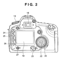
- FIG. 2 is a rear perspective view that shows the external appearance of the single-lens reflex digital camera according to the first embodiment of the present invention
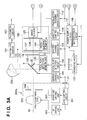
- FIGS. 3A and 3B are block diagrams that illustrate the configuration of the single-lens reflex digital camera according to the first embodiment
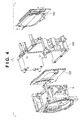
- FIG. 4 is an exploded oblique perspective view that illustrates the schematic configuration of the camera interior in order to illustrate the support structure around an infrared cut-off filter and an image sensor;
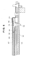
- FIG. 5 is an oblique perspective view that shows the configuration of a photographing unit
- FIG. 6 is a sectional view along a line A-A shown in FIG. 4 ;
- FIG. 7 is a perspective view that illustrates the detailed configuration of a vibration unit
- FIG. 8 is a detail view of a piezo-electric element in the first embodiment
- FIG. 9 is a side view that illustrates an infrared cut-off filter vibrating in a mode having 20 nodes
- FIG. 10 is a side view that illustrates an infrared cut-off filter vibrates in a mode having 19 nodes
- FIG. 11 is a front view that illustrates a blade unit in a focal plane shutter immediately before movement according to the first embodiment
- FIG. 12 is a front view that illustrates a a blade unit in a focal plane shutter immediately after movement according to the first embodiment
- FIG. 13 is a main part plan view showing a charge completion state of the focal plane shutter
- FIG. 14 is a main part plan view showing a release state (state prior to start of charging) of leading blades and trailing blades of the focal plane shutter;
- FIG. 15 is a main part plan view showing a state during charging of the focal plane shutter
- FIG. 16 is a main part plan view showing a state during charging of the focal plane shutter
- FIG. 17 is a main part plan view showing a state during charging of the focal plane shutter
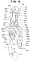
- FIG. 18 is a main part plan view showing an overcharge state of the focal plane shutter
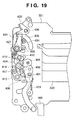
- FIG. 19 is a main part plan view of the focal plane shutter
- FIG. 20 is an overall exploded perspective view of the focal plane shutter
- FIGS. 21A to 21C are views showing a backface monitor display when in a cleaning mode
- FIG. 22 is a flowchart illustrating sensor cleaning processing according to the first embodiment
- FIG. 23 is a flowchart illustrating a sensor cleaning process according to the first embodiment
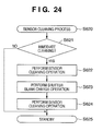
- FIG. 24 is a flowchart illustrating a driving sequence of a piezo-electric element and a shutter at a time of the sensor cleaning process
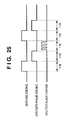
- FIG. 25 is a view that illustrates driving timing of a piezo-electric element and a shutter at a time of the sensor cleaning process
- FIGS. 26A to 26C are conceptual diagrams that illustrate dust removal in the sensor cleaning process
- FIG. 27 is a flowchart illustrating a sensor cleaning process according to a second embodiment
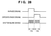
- FIG. 28 is a view illustrating driving timing of a piezo-electric element and a shutter at a time of the sensor cleaning process according to the second embodiment
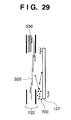
- FIG. 29 is a conceptual diagram that illustrates dust removal in the sensor cleaning process according to the second embodiment.
- FIG. 30 is a flowchart illustrating a sensor cleaning process according to a third embodiment.
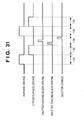
- FIG. 31 is a view illustrating driving timing of a piezo-electric element and a shutter at a time of the sensor cleaning process according to the third embodiment.
- FIG. 1 and FIG. 2 are perspective views that show the external appearance of a single-lens reflex digital camera as a first embodiment of an image capturing apparatus according to the present invention. More specifically, FIG. 1 is a perspective view as seen from the front surface side of the camera, and it shows a state in which a photographing lens unit is detached. FIG. 2 is a perspective view as seen from the rear surface side of the camera.
- reference numeral 1 denotes a camera main unit that is provided with a grip portion 1a that protrudes toward the front to make it easy for a user to stabilize and grip the camera when photographing.
- Reference numeral 2 denotes a mount portion for fixing a detachable photographing lens unit 200a (see FIG. 3A ) to the camera main unit 1.
- a mount contact point 21 has a function of exchanging control signals, status signals, data signals, and the like between the camera main unit 1 and the photographing lens unit 200a and also of supplying power to the photographing lens unit side. Further, the mount contact point 21 may be configured to enable not only electrical communication, but also optical communication and speech communication and the like.
- the photographing lens unit 200a is a photographing optical system that causes an optical image of an object to be formed on an image sensor 123 that is described later.
- Reference numeral 4 denotes a lens-lock release button that is pressed when detaching the photographing lens unit 200a.
- Reference numeral 5 denotes a mirror box that is disposed inside the camera case. A photographing light beam that passes through the photographing lens is guided to the mirror box 5.
- a quick return mirror 6 is provided inside the mirror box 5.
- the quick return mirror 6 can take a first position and a second position.
- the term "first position” refers to a position at which the quick return mirror 6 is retained at an angle of 45° with respect to the photographing optical axis in order to guide a photographing light beam in the direction of a pentaprism 22a (see FIG. 3A ) that is described later.
- the term “second position” refers to a position at which the quick return mirror 6 is withdrawn from the path of a photographing light beam in order to guide the photographing light beam in the direction of an image sensor 123 (see FIG. 3A ) that is described later.
- a shutter button 7 as an activation switch for starting photographing and a main operation dial 8 for setting a shutter speed or a lens aperture value in accordance with an operation mode when photographing.
- An operation mode setting button 10 for setting an operation mode of the photographing system is also provided. A part of the operation results of these operation members is displayed on an LCD display panel 9.
- the shutter button 7 is configured so that a switch SW1 (7a in FIG. 3B ) is turned on with a first stroke (half-depression) and a switch SW2 (7b in FIG. 3B ) is turned on with a second stroke (full depression).
- the operation mode setting button 10 is a button for making settings such as whether to photograph continuous exposures or only one frame when the shutter button 7 is pressed once as well as setting a "self photographing" mode and the like. The setting status thereof is displayed on the LCD display panel 9.
- a strobe unit 11 that pops up from the camera main unit 1, a shoe groove 12 for attaching a flash, and a flash contact point 13.
- a photographing mode setting dial 14 Toward the right side on the upper part of the camera ( FIG. 1 ) is disposed a photographing mode setting dial 14.
- an external terminal cover 15 On the side surface on the opposite side to the grip side is provided an external terminal cover 15 that is capable of opening and closing.
- a video signal output jack 16 and a USB output connector 17 are housed as external interfaces on the inside of the external terminal cover 15.
- a finder eyepiece window 18 is provided at the upper part thereof and a display such as a backface monitor 19 that is capable of displaying an image is provided in the vicinity of the center of the back surface.
- the backface monitor 19 comprises a liquid crystal panel for displaying color images, and performs the following types of display. That is, the backface monitor 19 displays various selectable setting items relating to photographed images when a menu button 24 is depressed. When an Info button 25 is depressed, the backface monitor 19 displays a list of the status of various setting items relating to photographed images. Further, when a display button 26 is depressed, the backface monitor 19 displays images that are recorded in recording media or displays an image immediately after photographing.
- Reference numeral 20 denotes a sub-operation dial.
- the following operations are performed when the sub-operation dial 20 is rotated in the clockwise direction or counter-clockwise direction. That is, operations are performed to change the settings of a light control amount correction value, change the settings for ISO sensitivity, and change the settings for a WB mode that are photographing information. Further, operations are performed to select various setting items relating to photographed images that are displayed by pressing the menu button 24 or to transfer a photographed image.
- Reference numeral 22 denotes a SET button.
- the SET button 22 is configured to input a decision from a user regarding various setting items relating to a photographed image that is displayed by pressing the menu button 24 and selected using the sub-operation dial 20.
- Reference numeral 23 denotes a main switch that is a power switch for activating or stopping operation of the camera.
- Reference numeral 24 denotes the menu button that is configured to cause various setting items relating to photographed images to be displayed on the backface monitor 19.
- Reference numeral 25 denotes the Info button.
- the Info button 25 When the Info button 25 is depressed, a list showing the status of various setting items relating to photographed images is displayed on the backface monitor 19.
- Reference numeral 26 denotes the display button. When the display button 26 is depressed, images that are recorded on recording media can be displayed.
- Reference numeral 27 denotes an image delete button. When the delete button 27 is depressed, an image that is displayed on the backface monitor 19 is deleted and disposed of.
- a cleaning mode according to the present embodiment is displayed on the backface monitor 19 as one of various setting items by depressing the menu button.
- the cleaning mode will be described in detail later.
- FIGS. 3A and 3B are block diagrams that illustrate the principal electrical configuration of the single-lens reflex digital camera according to the present embodiment.
- FIGS. 3A and 3B the parts that are common to both FIG. 1 and FIG. 2 are denoted by the same reference numerals.
- Reference numeral 100 denotes a central processing unit (hereunder, referred to as "MPU") comprising a microcomputer that is housed inside the camera main unit.
- the MPU 100 is responsible for the operational control of the camera and executes various kinds of processing and instructions with respect to each component by executing programs stored in a storage means (not shown).
- Reference numeral 100a denotes an EEPROM that is housed inside the MPU 100.
- the EEPROM 100a can store clock information of a time measurement circuit 110 and other information.
- a mirror driving unit 101 To the MPU 100 are connected a mirror driving unit 101, a focal point detection circuit 102, a shutter charge driving unit 103, a shutter control unit 104, a video signal processing circuit 105, a switch sense circuit 106, and a photometry circuit 107. Further, a liquid crystal display driving circuit 108, a battery check circuit 109, a time measurement circuit 110, a power supply circuit 111, and a piezo-electric element driving circuit 112 are also connected to the MPU 100.
- the MPU 100 performs communication with a lens control circuit 201 that is provided inside the photographing lens unit 200a via the mount contact point 21.
- the mount contact point 21 also comprises a function that sends a signal to the MPU 100 when the photographing lens unit 200a is connected.
- the lens control circuit 201 can carry out communication with the MPU 100, and can perform driving of the aperture 204 and the photographing lens 200 inside the photographing lens unit 200a via the AF driving unit 202 and the aperture driving unit 203.
- the photographing lens 200 is illustrated as a single lens for convenience, in fact the photographing lens 200 may be constituted by a group of multiple lenses.
- the AF driving unit 202 is constituted by, for example, a stepping motor, and performs adjustment so as to focus a photographing light beam on the image sensor 123 by altering a focus lens position inside the photographing lens 200 through control of the lens control circuit 201.
- the aperture driving unit 203 is constituted by, for example, an auto iris, and is configured so as to alter the aperture 204 using the lens control circuit 201 to obtain an optical aperture value.
- the quick return mirror 6 guides a photographing light beam that passes through the photographing lens 200 to the pentaprism 22a, and also allows a portion thereof to penetrate through to be guided to a sub-mirror 30.
- the sub-mirror 30 guides the photographing light beam that penetrates through to a focal point detection sensor unit 120.
- the mirror driving unit 101 drives the quick return mirror 6 to a position at which an object image is observable by the finder and to a position at which it is sheltered from a photographing light beam. Simultaneously with such operations, the mirror driving unit 101 drives the sub-mirror 30 to a position at which it guides a photographing light beam to the focal point detection sensor unit 120, and to a position at which is which it is sheltered from a photographing light beam. More specifically, the mirror driving unit 101 is comprised by, for example, a DC motor and a gear train.
- the focal point detection sensor unit 120 uses a known phase difference detection system that comprises a field lens, a reflection mirror, a secondary image forming lens, an aperture, and a line sensor consisting of a plurality of CCDs and the like that that are disposed in the vicinity of an image forming surface (not shown).
- a signal that is output from the focal point detection sensor unit 120 is supplied to the focal point detection circuit 102, converted to an object image signal, and thereafter sent to the MPU 100.
- the MPU 100 performs a focal point detection calculation according to a phase difference detection method based on this object image signal.
- the MPU 100 determines a defocus amount and a defocus direction, and based on these results drives a focus lens inside the photographing lens 200 towards a focus position via the lens control circuit 201 and the AF driving unit 202.
- the pentaprism 22a is an optical member that converts and reflects a photographing light beam that is reflected by the quick return mirror 6 into an erect normal image. A user can observe an object image from the finder eyepiece window 18 via the finder optical system.
- the pentaprism 22a also guides one portion of a photographing light beam to the photometric sensor 121.
- the photometry circuit 107 obtains the output of the photometric sensor 121, converts the output to brightness signals for each area on the observation plane, and outputs the brightness signals to the MPU 100.
- the MPU 100 calculates an exposure value based on the brightness signals that are obtained in this manner.
- Reference numeral 122 denotes a mechanical focal plane shutter that blocks the photographing light beam when a user is observing an object image using the finder.
- the focal plane shutter 122 is disposed at a position in which there is a slight gap between the focal plane shutter 122 and an infrared cut-off filter 127 that is described later. Further, the focal plane shutter 122 is configured so as to obtain a desired exposure time by a time difference between the movement of a group of one or more leading blades and the movement of a group of one or more trailing blades, described later, in accordance with a release signal when capturing an image.
- the focal plane shutter 122 is subjected to shutter charge driving by a shutter charge driving unit 103 by the shutter control unit 104 upon receiving a command from the MPU 100, after movement of the group of leading blades and the group of trailing blades that are described later.
- Reference numeral 123 denotes the image sensor, for example, a CMOS circuit.
- CMOS complementary metal-oxide-semiconductor
- Various forms are available for this image capturing device, such as a CCD type, a CMOS type, and a CID type, and an image capturing device of any form may be employed.
- Light that is received in a region of image-capturing field of the image sensor 123 is captured as an image.
- the center of the image-capturing field is normally made to match the lens optical axis of the photographing lens 200, in cropped photographing and the like in which an image is captured using only a potion of the pixels of the image sensor 123, there are cases in which the center of the image-capturing field is not made to match the lens optical axis.
- Reference numeral 124 in Fig. 3B denotes a clamp/CDS (correlated double sampling) circuit that performs basic analog processing prior to A/D conversion and that can also change a clamp level.
- Reference numeral 125 denotes an AGC (automatic gain control circuit) that performs basic analog processing prior to A/D conversion and that can also change an AGC basic level.
- Reference numeral 126 denotes an A/D converter that converts an analog output signal of the image sensor 123 into a digital signal.
- Reference numeral 127 in Fig. 3A denotes an infrared cut-off filter that has a substantially oblong shape.
- the infrared cut-off filter 127 cuts off unwanted infrared light of a light beam that is incident on the image sensor 123.
- the surface is covered with an electrically conductive material.
- Reference numeral 128 denotes an optical low pass filter that has a substantially oblong shape.
- the optical low pass filter 128, a plurality of phase plates and birefringent plates comprising quartz crystal or the like are fixed together and laminated.
- the optical low pass filter 128 divides a light beam that is incident on the image sensor 123 into a plurality of beams to effectively reduce the occurrence of spurious resolution signals or spurious color signals.
- Reference numeral 129 denotes an excitation member that imparts a vibration to the infrared cut-off filter 127.
- a piezo-electric element is used as the excitation member 129.
- the excitation member 129 is excited by the piezo-electric element driving circuit 112 upon receipt of a command from the MPU 100, and is configured to vibrate integrally with the infrared cut-off filter 127.
- Reference numeral 150 denotes a photographing unit in which the infrared cut-off filter 127, the piezo-electric element 129, the image sensor 123, and other components that are described later are formed into a unit. The detailed configuration of the photographing unit 150 is described later.
- the video signal processing circuit 105 in Fig. 3B executes overall image processing by hardware, such as gamma/knee processing, filtering, and information synthesis processing for monitor display for the digitalized image data.
- the image data for display from the video signal processing circuit 105 is displayed on the backface monitor 19 via the monitor driving circuit 131.
- the video signal processing circuit 105 is also capable of storing image data in a buffer memory 133 through a memory controller 132 in accordance with an instruction of the MPU 100. Further, the video signal processing circuit 105 also has a function of compressing image data such as JPEG data.
- the video signal processing circuit 105 can temporarily store image data in the buffer memory 133 and thereafter sequentially read out unprocessed image data through the memory controller 132.
- the video signal processing circuit 105 is capable of sequentially performing image processing or compression processing irrespective of the speed of image data that is input from the A/D converter 126.
- the memory controller 132 has a function that stores image data that is input from an external interface 135 (corresponds to the video signal output jack 16 and the USB output connector 17 shown in FIG. 1 ) in a memory 134.
- the memory controller 132 also has a function that outputs image data that is stored in the memory 134 from the external interface 135.
- the memory 134 is a flash memory or the like that is detachable from the camera main unit 1.
- the switch sense circuit 106 sends input signals to the MPU 100 in accordance with the operation state of each switch.
- Reference numeral 7a denotes a switch SW1 that is turned on by a first stroke (half-depression) of the shutter button 7.
- Reference numeral 7b denotes a switch SW2 that is turned on by a second stroke (full depression) of the shutter button 7.
- start of photographing is instructed to the MPU 100.
- the main operation dial 8, the sub-operation dial 20, the SET button 22, the photographing mode setting dial 14, the main switch 23, the menu button 24, the Info button 25, the display button 26, and the delete button 27 are also connected to the switch sense circuit 106.
- the liquid crystal display driving circuit 108 drives the LCD display panel 9 or an in-finder liquid crystal display 136 in accordance with an instruction of the MPU 100.
- Reference numeral 109 denotes a battery check circuit.
- the battery check circuit 109 performs a battery check for a predetermined time in accordance with a signal from the MPU 100 and sends the check result to the MPU 100.
- Reference numeral 137 denotes a power source that supplies necessary power to each component of the camera main unit 1.
- the time measurement circuit 110 measures a time or date from when the main switch 23 is turned off until the main switch 23 is next turned on, and can send the measurement result to the MPU 100 in accordance with a command from the MPU 100.
- FIG. 4 is an exploded perspective view that illustrates the schematic configuration of the inside of the camera main unit 1 to describe the support structure around the photographing unit 150.
- the photographing unit 150 is disposed on the image side of the main unit chassis 160.
- the photographing unit 150 is fixed by ensuring that the image capturing surface of the image sensor 123 is disposed in parallel with, and at a clearance a predetermined distance from, the attachment surface of the mount portion 2 that serves as a reference to which the photographing lens unit 200a is attached, shown in Fig. 1 .
- FIG. 5 is a perspective view that shows the configuration of the photographing unit 150.
- the photographing unit 150 comprises a vibration unit 170, an image sensor unit 180, and an elastic member 190.
- the vibration unit 170 is fixed to the image sensor unit 180 in a manner sandwiching the elastic member 190 therebetween. This configuration will be described in detail later.
- the image sensor unit 180 comprises at least the image sensor 123 and a fixing member 181.
- the vibration unit 170 comprises the infrared cut-off filter 127, the piezo-electric element 129 (see FIG. 3A ), an urging member 171 and the like.
- An electrical circuit of an image capturing system is mounted on a circuit board 182.
- a shield case 183 is formed by a metal or the like that has electrical conductivity.
- the circuit board 182 and the shield case 183 are engaged with the fixing member 181 by means of a screw or the like.
- the shield case 183 is connected to ground potential on a circuit for protecting the electrical circuit from static electricity.
- shading member 184 an opening is formed that corresponds to an effective area of the photo-electric conversion surface of the image sensor 123, and double-faced adhesive tape is affixed to the object side and the image side thereof.
- An optical low-pass filter retaining member 185 is affixed to the cover glass of the image sensor 123 by the double-faced adhesive tape of the shading member 184.
- the optical low-pass filter 128 is positioned at the location of an opening of the optical low-pass filter retaining member 185, and is fixingly held on the shading member 184 with double-faced adhesive tape.
- FIG. 6 is a sectional view of one portion of the photographing unit 150 along a line A-A shown in FIG. 4 .
- the surface on the object side of the shading member 184 (the top surface in the Figure) is in contact with the optical low-pass filter 128, and the surface on the image side thereof is in contact with the cover glass of the image sensor 123.
- Double-faced adhesive tape is affixed to the object side and the image side of the shading member 184.
- the optical low-pass filter 128 is fixingly retained on the cover glass of the image sensor 123 by the double-faced adhesive tape of the shading member 184.
- the region between the optical low-pass filter 128 and the cover glass of the image sensor 123 is sealed by the shading member 184 in a manner forming an enclosed space that prevents entry of foreign substances such as dust.
- the surface on the object side of the elastic member 190 contacts against the infrared cut-off filter 127, and the surface on the image side thereof contacts against the optical low-pass filter 128.
- the vibration unit 170 is urged towards the photographing unit 150 side by the resilience of the urging member 171. Therefore the elastic member 190 and the infrared cut-off filter 127 contact each other without any clearance therebetween and, similarly, the elastic member 190 and the optical low pass filter 128 also contact each other without any clearance therebetween.
- the area between the infrared cut-off filter 127 and the optical low pass filter 128 is sealed by the elastic member 190 in a manner forming an enclosed space that prevents entry of foreign substances such as dust.
- FIG. 7 is a perspective view that illustrates the detailed configuration of the vibration unit 170.
- reference numerals 129a and 129b denote piezo-electric elements that are affixed to the ends of the infrared cut-off filter 127 using fixing means such as, for example, an adhesive.
- a total of two piezo-electric elements 129a and 129b having the same shape are affixed to the two opposite ends of the infrared cut-off filter 127.
- FIG. 8 is a detailed view of the piezo-electric elements 129a and 129b.
- an electrode is provided on a B surface of the piezo-electric elements 129a and 129b.
- the electrode may be formed by printing, for example, using an electrode material such as silver.
- This electrode is divided into a + phase region and a G phase region for exciting a flexural vibration in the infrared cut-off filter 127.
- an electrode is provided over substantially the entire area of the C surface of the piezo-electric elements 129a and 129b. This electrode on the C surface is electrically connected with the G phase of the B surface by an unshown conductive material or the like, and the G phase regions are both maintained at the same electric potential.
- An unshown conductive link member such as a flexible printed wiring board is fixingly adhered by a method such as fastening with glue to the B surface, to enable predetermined voltages to be independently applied to the + phase and the G phase, respectively.
- the C surface of the piezo-electric elements 129a and 129b is fixingly adhered to the infrared cut-off filter 127 by a method such as fastening with glue, so that the piezo-electric elements 129a and 129b and the infrared cut-off filter 127 move in an integrated manner.
- FIG. 9 is a side view as viewed from the top surface of the camera that illustrates a vibration shape when the infrared cut-off filter 127 vibrates in a mode having 20 nodes.
- FIG. 10 is a side view as viewed from the top surface of the camera that illustrates a vibration shape when the infrared cut-off filter 127 vibrates in a mode having 19 nodes.
- deformation of the infrared cut-off filter 127 and the piezo-electric elements 129a and 129b is described in a case in which, taking the respective G phases thereof as a ground potential (0V), a positive voltage is applied to the respective + phases of the piezo-electric element 129a and the piezo-electric element 129b through an unshown conductive link member.
- the + phase of the piezo-electric element contracts in a perpendicular direction to the surface and extends in an in-plane direction. Therefore, the surface of the infrared cut-off filter 127 that is bonded with the piezo-electric elements 129a and 129b receives a force from the piezo-electric elements 129a and 129b that expands the bonded surface in the in-plane direction. As a result, a deformation is produced such that the surface side that is bonded with the piezo-electric elements forms a convex shape.
- deformation of the piezo-electric elements 129a and 129b is described in a case in which, taking the respective G phases thereof as a ground (OV), a positive voltage is applied to the + phase of the piezo-electric element 129a and a negative voltage is applied to the + phase of the piezo-electric element 129b through a conductive link member.
- a positive voltage is applied to the + phase of the piezo-electric element 129a and a negative voltage is applied to the + phase of the piezo-electric element 129b through a conductive link member.
- a flexural vibration occurs that has a shape in which the number of nodes of the vibration is even as shown in FIG. 9 .
- the periodic voltages that are applied to the respective + phases are staggered by half a wavelength so that the voltages are in opposite phase (opposite-phase driving)
- a flexural vibration occurs that has a shape in which the number of nodes of the vibration is odd as shown in FIG. 10 .
- the frequency of these periodic voltages approximate to the resonance frequency of an inherent mode of the infrared cut-off filter 127, a larger amplitude can be obtained with a smaller voltage.
- the resonance frequency of an inherent mode of the infrared cut-off filter 127 will differ according to the shape, plate thickness, material properties and the like of the infrared cut-off filter 127, in order not to generate undesirable noise it is preferable to select an inherent mode such that the resonance frequency is outside the audible range.
- the present embodiment has been described taking as an example a mode in which 20 nodes emerge and a mode in which 19 nodes emerge, the present invention is not limited thereto, and the present embodiment may be configured to generate vibrations other than these, or may use three or more kinds of vibration modes.
- a configuration is adopted in which a flexural vibration is induced in the infrared cut-off filter 127.
- a configuration may also be adopted in which a flexural vibration is induced in the optical low pass filter 128 that is constituted by lamination of the birefringent plate, the phase plate, and the infrared cut-off filter, or in which a flexural vibration is induced singly in only the birefringent plate or only the phase plate.
- FIG. 11 and FIG. 12 are front views of the focal plane shutter 122.
- FIG. 11 is a view that illustrates a movement preparation completed state before the shutter is released.
- FIG. 12 is a view that illustrates a movement completed state after the shutter is released.
- FIG. 13 is a drive mechanism main part plan view showing a charge completion state of the focal plane shutter 122.
- FIG. 14 is a mechanism main plan view showing a state in which a leading blade unit 320 that comprises shutter blades serving as a first shading member and a trailing blade unit 330 that comprises shutter blades serving as a second shading member are in an exposure completed state (state prior to start of charging).
- FIG. 15 to FIG. 17 are mechanism main part plan views that illustrate a state during charging.
- FIG. 18 is a mechanism main part plan view showing an overcharge state in which charging is completed.
- FIG. 19 is a top view centering on a driving section of the shutter in the charge completion state.
- FIG. 20 is a perspective view showing the configuration of the shutter overall. As shown in FIG. 19 and FIG. 20 , each member is disposed on a shutter base plate 301.
- reference number 301 denotes a base plate (hereunder referred to as "shutter base plate”) that has a shutter opening
- reference numeral 301a denotes the shutter opening
- Reference number 301b denotes a long hole for escaping from a movement path of a leading blade driving pin 416 of a leading driving lever (lever that imparts motion energy by a spring force or the like to a leading blade) 413, as described later, that is shown in FIG. 13 to 19 .
- Reference numeral 301c denotes a long hole for escaping from the movement path of a trailing blade driving pin 429 of a trailing driving lever (lever that imparts motion energy by a spring force or the like to a trailing blade) 426, as described later, that is shown in FIG. 13 to 19 .
- Reference numeral 302 denotes a leading blade slit-forming blade that has a leading blade slit-forming edge 302a.
- Reference numerals 303 to 305 denote leading blade covering blades, and are referred to, in order, as a first leading blade 303, a second leading blade 304, and a third leading blade 305.
- Reference numeral 306 denotes a leading blade first arm which is mounted so as to be freely turnable around a shaft 301d provided in the shutter base plate 301.
- the leading blade slit-forming blade 302 is rotatably supported with respect to the first arm 306 by a blanking dowel 308a that is provided on the leading edge side of the first arm 306.
- Reference numeral 306a denotes a hole into which the leading blade driving pin 416 of the leading driving lever 413 that is described later is inserted. Motive power is transferred from the leading driving lever 413 on which is provided a rotational shaft 414, described later, that is coaxial with the shaft 301d through the hole 306a.
- Reference numeral 307 denotes a leading blade second arm which is mounted so as to be able to swing in a freely rotatable manner around a shaft 301e provided in the shutter base plate 301.
- the leading blade slit-forming blade 302 is rotatably supported with respect to the second arm 307 by a blanking dowel 309a that is provided on the leading edge side of the second arm 307.
- a parallel link is formed by the leading blade slit-forming blade 302 and the leading blade first arm 306 and the leading blade second arm 307.
- the first leading blade 303, the second leading blade 304, and the third leading blade 305 are rotatably supported by blanking dowels 308b and 309b, 308c and 309c, and 308d and 309d, respectively, in the intermediate parts of the leading blade first arm 306 and the leading blade second arm 307.
- Parallel links are thereby formed.
- the leading blade unit 320 that is a first shading member is constituted by the members denoted by reference numerals 302 to 309.
- reference numeral 310 denotes a trailing blade slit-forming blade and reference numeral 310a denotes a trailing blade slit-forming edge.
- Reference numerals 311 to 313 denote trailing blade covering blades that are referred to, in order, as a first trailing blade 311, a second trailing blade 312, and a third trailing blade 313.
- Reference numeral 314 denotes a trailing blade first arm which is mounted to be freely turnable around a shaft 301f provided in the shutter base plate 301.
- the trailing blade slit-forming blade 310 is rotatably supported with respect to the first arm 314 by a blanking dowel 316a that is provided on the leading edge side of the first arm 314.
- Reference numeral 314a denotes a hole into which the trailing blade driving pin 429 of the trailing driving lever 426 that is described later is inserted. Motive power is transferred from the trailing driving lever 426 on which is provided a rotational shaft 427, described later, that is coaxial with the shaft 301f through the hole 314a.
- Reference numeral 315 denotes a trailing blade second arm which is mounted to freely turnable around a shaft 301g provided in the shutter base plate 301.
- the trailing blade slit-forming blade 310 is rotatably supported with respect to the second arm 315 by a blanking dowel 317a that is provided on the leading edge side of the second arm 315.
- a parallel link is formed by the trailing blade slit-forming blade 310 and the trailing blade first arm 314 and the trailing blade second arm 315.
- the first trailing blade 311, the second trailing blade 312, and the third trailing blade 313 are rotatably supported by blanking dowels 316b and 317b, 316c and 317c, and 316d and 317d, respectively, in the intermediate parts of the first arm 314 and the second arm 315 to thereby form parallel links.
- the trailing blade unit 330 that is a second shading member is constituted by the members denoted by reference numerals 310 to 317.
- reference numeral 401 denotes a charge lever as a power transmission member that is arranged to be driven by a power transmission member 460 of the camera main unit 1.
- the charge lever 401 is supported by a shaft 402 to be able to turn around the shaft 402 and is given an urging force in a counter-clockwise direction by a spring 403. Stoppers (not shown) are arranged to allow the charge lever 401 to turn between a position shown in FIG. 13 and another position shown in FIG. 18 . Further, the charge lever 401 has a connection hole 401a for allowing the charge lever 401 to turn integrally with a leading sub-charge lever 408 that is described later.
- Reference numeral 404 denotes a connection lever that is turnably supported for pivotal movement by the charge lever 401 and a charge cam lever 405 and is arranged to cause the charge cam lever 405 to turn in association with a turn of the charge lever 401.
- Reference numeral 405 denotes the charge cam lever as a first charge member that is turnably held by a shaft 406.
- the charge cam lever 405 has a cam part 405a that charges a leading blade driving spring 415 by abutting on a roller 417 of the leading driving lever 413 when charging the leading driving lever 413.
- the charge cam lever 405 also has a cam part 405b that charges a trailing blade driving spring 428 by abutting on a roller 430 of the trailing driving lever 426 when charging the trailing driving lever 426.
- a connection roller 407 which abuts on a trailing sub-charge lever 409 is rotatably supported by the charge cam lever 405.
- Reference numeral 408 denotes the leading sub-charge lever which is arranged to turn around the same shaft 402 as the charge lever 401.
- the leading sub-charge lever 408 has a cam part 408a which charges a leading sub-lever 418, described later, that is provided for charging a leading blade auxiliary spring 419.
- the leading sub-charge lever 408 also has a connection part 408b which is connected to the connection hole 401a of the charge lever 401 to cause the leading sub-charge lever 408 to turn integrally with the charge lever 401.
- Reference numeral 409 denotes the trailing sub-charge lever as a second charge member which is turnably held by a shaft 410 and is given an urging force in the clockwise direction by a spring 411 so as to constantly abut on the connection roller 407.
- a trailing sub-charge lever roller 412 On the trailing sub-charge lever 409, there is rotatably supported a trailing sub-charge lever roller 412 as a third roller which is able to abut on a trailing sub-lever 431.
- a trailing blade auxiliary spring 432 described later, is charged.
- Reference numeral 413 denotes the leading driving lever as a first driving member which is turnably supported by a shaft 414 and is provided with the leading driving lever roller 417 as a first roller which is able to abut on the cam part 405a of the charge cam lever 405.
- the leading driving lever 413 there is formed a locked part 413a which is arranged to be locked by a leading latch lever 423.
- the leading driving lever 413 is given an urging force in the clockwise direction by the leading blade driving spring 415, which serves as a first spring.
- the leading driving lever 413 is locked by the leading latch lever 423, and the leading blade unit 320 covers an aperture frame of the shutter.
- Reference numeral 418 denotes the leading sub-lever that is a fourth driving member which is turnably supported on the same shaft as the leading driving lever 413, and is given an urging force in the clockwise direction by the leading blade auxiliary spring 419, which serves as a fourth spring.
- the leading blade auxiliary spring 419 which serves as a fourth spring.
- Reference numeral 418b denotes a stopper part that is provided on the leading sub-lever 418, which is arranged to turn integrally with the leading driving lever 413 when the leading driving lever 413 turns.
- the stopper part 418b abuts on a leading stopper 421 which is formed with an elastic member made of rubber or a soft plastic material or the like on a leading stopper shaft 420.
- the stopper part 418b is arranged to bring a clockwise turn of the leading sub-lever 418 to a stop.
- Reference numeral 422 denotes a leading sub-lever roller that is rotatably supported by the leading sub-lever 418 and is arranged to impart a force to the leading sub-lever 418 by abutting on the cam part 408a of the leading sub-charge lever 408.
- Reference numeral 423 denotes the leading latch lever which is turnably supported around a shaft 424 and is given an urging force in the counter-clockwise direction by a spring 425. In the state shown in FIG. 13 , any further counter-clockwise turn of the leading latch lever 423 is prevented by an unshown stopper.
- Reference numeral 423a denotes a lock part that is arranged to abut on the locked part 413a of the leading driving lever 413 to prevent the leading driving lever 413 from turning in the clockwise direction.
- Reference numeral 426 denotes the trailing driving lever that serves as a second driving member which is turnably supported by a shaft 427 and is provided with the trailing driving lever roller 430 as a second roller which is arranged to abut on the cam part 405b of the charge cam lever 405.
- the trailing driving lever 426 is further provided with a locked part 426a which is arranged to be locked by a trailing latch lever 435 and is given an urging force in the clockwise direction by the trailing blade driving spring 428, which serves as a second spring. In the state shown in FIG. 13 , the trailing driving lever 426 is locked by the trailing latch lever 435, and the trailing blade unit 330 uncovers the aperture frame of the shutter.
- Reference numeral 431 denotes the trailing sub-lever as a third driving member.
- the trailing sub-lever 431 is turnably supported on the same shaft as the trailing driving lever 426 and is given an urging force in the clockwise direction by the trailing blade auxiliary spring 432, which serves as a third spring.
- the trailing blade driving pin 429 which is provided on the trailing driving lever 426 is abutting on an abutting part 431a of the trailing sub-lever 431 to allow the spring force of the trailing blade auxiliary spring 432 to be exerted also to the trailing driving lever 426.
- Reference numeral 431b denotes a stopper part that is provided on the trailing sub-lever 431 which turns integrally with the trailing driving lever 426 when the trailing driving lever 426 turns.
- the stopper part 431b is arranged to abut on a trailing stopper 434 which is formed by an elastic member made of rubber or a soft plastic material or the like and is provided on a trailing stopper shaft 433.
- Reference numeral 431c denotes a charge cam part that serves as a third cam part and is provided on the trailing sub-lever 431.
- the charge cam part 431c is arranged to abut on the trailing sub-charge lever roller 412 that serves as a third roller and is rotatably supported on the trailing sub-charge lever 409.
- the trailing sub-lever 431 is charged by a turning motion in the counter-clockwise direction of the trailing sub-charge lever 409.
- Reference numeral 435 denotes the trailing latch lever which is turnably supported around a shaft 436 and is given an urging force in the counter-clockwise direction by a spring 437. In the state shown in FIG. 13 , any further counter-clockwise turn of the trailing latch lever 435 is prevented by an unshown stopper.
- Reference numeral 435a denotes a lock part that is arranged to abut on the locked part 426a of the trailing driving lever 426 to prevent the trailing driving lever 426 from turning in the clockwise direction.
- Reference numeral 441 denotes a magnetized leading blade rotor having a rotational shaft on which is mounted a leading blade hammer 446 that is arranged to abut on the leading latch lever 423.
- Reference numeral 442 denotes a leading blade stator that is disposed on a base member 444.
- Reference numeral 443 denotes a leading blade coil that is wound around a part of the leading blade stator 442.
- Reference numeral 447 denotes a return spring that is arranged to urge the leading blade rotor 441 and the leading blade hammer 446 to move in a predetermined direction.
- the running of the trailing blade unit 330 is started by a similar operation being performed by a trailing blade rotor (not shown), a trailing blade stator 448, a trailing blade coil 449, a return spring 451, and a trailing blade hammer 450 which is arranged to abut on the trailing latch lever 435.
- Reference numeral 452 denotes a printed circuit board which is connected to the leading blade coil 443 and the trailing blade coil 449 to allow these coils to be energized by a power supply from the camera main unit 1.
- the MPU 100 Upon the switch SW2 being turned on when the photographer depresses the shutter button 7 to perform photographing, the MPU 100 receives an instruction to start photographing. The MPU 100 starts driving control of the focal plane shutter 122 by the shutter control unit 104.
- leading blade unit 320 begins to travel as a result of the spring forces of the leading blade driving spring 415 and the leading blade auxiliary spring 419.
- the leading blade rotor 441 and the leading blade hammer 446 are returned to predetermined positions by the urging force of the return spring 447.
- the trailing blade rotor When a current is passed to the trailing blade coil 449 after the lapse of a predetermined period of time from the commencement of travel of the leading blade unit 320, the trailing blade rotor which is not shown rotates to cause the trailing blade hammer 450 to abut on the trailing latch lever 435 to move the trailing latch lever 435. As a result, the trailing driving lever 426 is released from a latched state. Thereafter, the trailing blade unit 330 begins to travel as a result of the spring forces of the trailing blade driving spring 428 and the trailing blade auxiliary spring 432.
- the shutter is thus arranged to independently perform release actions with the leading blade unit 320 and the trailing blade unit 330 by means of a plurality of electromagnetic driving devices as described above.
- leading driving lever 413 and the leading sub-lever 418 integrally driven by the urging forces of the leading blade driving spring 415 and the leading blade auxiliary spring 419 to cause the leading blade unit 320 to move from a closed position to an open position via a leading blade driving pin 416.
- the stopper part 418b of the leading sub-lever 418 comes to abut on the leading stopper 421 to reduce noise and soften an impact before the stopper part 418b finally abuts on the leading stopper shaft 420 to accurately define the operating range of the leading blade auxiliary spring 419.
- the urging force of the leading blade auxiliary spring 419 onto the leading driving lever 413 is thus removed to allow the leading driving lever 413 to be driven solely by the leading blade driving spring 415 to a stopper (not shown) arranged to define the open position.
- the trailing driving lever 426 and the trailing sub-lever 431 are integrally driven by the urging forces of the trailing blade driving spring 428 and the trailing blade auxiliary spring 432 to cause unshown trailing blades to move from an open position to a closed position via a trailing blade driving pin 429. While the movement of the trailing blades is in process, the stopper part 431b of the trailing sub-lever 431 comes to abut on the trailing stopper 434 to reduce noise and soften an impact before the stopper part 431b finally abuts on the trailing stopper shaft 433 to accurately define the operating range of the trailing blade auxiliary spring 432.
- the urging force of the trailing blade auxiliary spring 432 onto the trailing driving lever 426 is thus removed to allow the trailing driving lever 426 to be driven solely by the trailing blade driving spring 428 to a stopper (not shown) arranged to define the closed position, whereby an exposure operation (photographing operation) is completed and the shutter is brought to the state shown in FIG. 14 .
- the charge cam lever 405 When the charge lever 401 is turned in the clockwise direction so as to bring the shutter into a photography-enabled standby state from the state shown in FIG. 14 (state immediately after completion of photographing), the charge cam lever 405 is also turned in the clockwise direction via the connection lever 404. The clockwise turn of the charge cam lever 405 causes the cam part 405a to abut on the leading driving lever roller 417 to turn the leading driving lever 413 in the counter-clockwise direction. As a result, the leading blade driving spring 415 starts to be charged and the leading blade unit 320 begins to move toward the closed position (state shown in FIG. 15 ).
- the leading sub-charge lever 408 that is integrally connected to the charge lever 401 turns in the clockwise direction to bring the cam part 408a into abutment with the leading sub-lever roller 422, thereby causing the leading sub-lever 418 to turn in the counter-clockwise direction.
- the leading blade auxiliary spring 419 starts to be charged.
- the trailing sub-charge lever 409 that is in abutment with the connection roller 407 is turned in the counter-clockwise direction.
- the trailing sub-charge lever roller 412 provided on the trailing sub-charge lever 409 comes into abutment with a charge cam 431c to cause the trailing sub-lever 431 to start to turn in the counter-clockwise direction.
- the trailing blade auxiliary spring 432 starts to be charged.
- leading blade driving spring 415, the leading blade auxiliary spring 419 and the trailing blade auxiliary spring 432 start to be charged at substantially the same time (state shown in FIG. 16 ).
- the trailing driving lever 426 starts to turn after the leading driving lever 413 has started to turn. Therefore, the trailing blade driving spring 428 starts to be charged after the start of charging of the leading blade driving spring 415, the leading blade auxiliary spring 419 and the trailing blade auxiliary spring 432.
- FIG. 18 shows the overcharged state in which the charge lever 401 is brought in abutment with a stopper (not shown) and turned in the clockwise direction to the greatest extent.
- the locked part 413a of the leading driving lever 413 moves over the lock part 423a of the leading latch lever 423.
- the leading blade unit 320 and the trailing blade unit 330 are both driven to a charged position that is slightly further than charge completion state shown in FIG. 13 .
- leading blade unit 320 and the trailing blade unit 330 are instantly returned to the charge completion state at a speed that is equivalent to that at the time of exposure driving of the leading blade unit 320 and the trailing blade unit 330.
- the locked part 426a of the trailing driving lever 426 also moves over the lock part 435a of the trailing latch lever 435. Accordingly, even if the clockwise turning of the charge lever 401 is cancelled, the leading driving lever 413 and the trailing driving lever 426 respectively enter a state in which a turn in the clockwise direction can be locked.
- the charge lever 401 turns in the counter-clockwise direction together with the charge cam lever 405 and the leading sub-charge lever 408 via the connection lever 404 under the spring force of the spring 403. Further, the spring 411 causes the trailing sub-charge lever 409 to turn in the clockwise direction to return the shutter to the state shown in FIG. 13 in which charging is completed.
- the charge lever 401 is further charged by the power transmission member 460 that is one part of the shutter charge driving unit 103 of the camera main unit 1 (hereunder, referred to as a "blank charge operation").
- the power transmission member 460 that is one part of the shutter charge driving unit 103 of the camera main unit 1 (hereunder, referred to as a "blank charge operation").
- the overcharge operation shown in FIG. 18 is performed.
- the leading blade unit 320 and the trailing blade unit 330 are both driven to a charged position that is slightly further than the charge completion state shown in FIG. 13 .
- the leading blade unit 320 and the trailing blade unit 330 are instantly returned to the charge completion state at a speed that is equivalent to that at the time of exposure driving.
- an impact force is applied to the leading blade unit 320 and the trailing blade unit 330.
- the leading blade unit 320 and the trailing blade unit 330 are repeatedly driven by a slight amount.
- the leading blade unit 320 and the trailing blade unit 330 perform a vibrating action.
- a configuration is adopted in which the leading blade unit 320 is driven with the leading blade driving spring 415 and the leading blade auxiliary spring 419, and the trailing blade unit 330 is driven with the trailing blade driving spring 428 and the trailing blade auxiliary spring 432.
- the configuration is such that the urging forces of the leading blade auxiliary spring 419 and the trailing blade auxiliary spring 432 only act at initial stage of driving the respective blades. Therefore, a strong spring force (force of leading blade driving spring 415 + leading blade auxiliary spring 419, and force of trailing blade driving spring 428 + trailing blade auxiliary spring 432) can be used at the start time of the blades to cause the blades to reach a desired curtain speed in a short time.
- a large accelerating force is unnecessary after reaching a predetermined curtain speed since an inertial force also acts, the curtain speed can be maintained even with a comparatively weak spring force (force of leading blade driving spring 415 and trailing blade driving spring 428).
- leading blade auxiliary spring 419 that has a spring force greater than the spring force of the leading blade driving spring 415, and the trailing blade auxiliary spring 432 that has a spring force greater than the spring force of the trailing blade driving spring 428 are charged using a region that is larger than an action region at the time of an exposure operation. It is therefore possible to disperse energy and the lower a peak of a force required for charging.
- leading blade auxiliary spring 419 and the trailing blade auxiliary spring 432 are charged using substantially the entire region of the charge region of the leading blade driving spring 415. It is therefore possible to reduce the peak of the overall charging force required to charge all the springs, and to make the overall charging force inside the charging region uniform.
- the operating angles of the leading sub-lever 418 (leading blade auxiliary spring 419) and the trailing sub-lever 431 (trailing blade auxiliary spring 432) are set so that an urging force is not allowed to act in a range of from approximately 15° to 45° from their respective latch engagement positions.
- a favorable acceleration performance can be obtained by adopting this configuration, a configuration may also be adopted in which the leading blade auxiliary spring 419 and the trailing blade auxiliary spring 432 apply an urging force to the entire shutter operation region.
- the charge lever 401 turns the charge cam lever 405 in the clockwise direction via the connection lever 404 to performing charging.
- a configuration may also be adopted in which the leading sub-charge lever 408 or the trailing sub-charge lever 409 is removed, and the leading blade auxiliary spring 419 or the trailing blade auxiliary spring 432 is charged via the leading driving lever 413 or the trailing driving lever 426.
- FIGS. 21A to 21C are views that illustrate displays on the backface monitor 19 when the camera main unit 1 is switched to a cleaning mode state by depression of the menu button 24.
- FIG. 22 to FIG. 23 are views that illustrate the flow of a sensor cleaning process in the cleaning mode.
- FIG. 25 is a view that illustrates the driving sequence of the piezo-electric element 129 and the shutter during a sensor cleaning process.
- FIG. 26 is a view illustrating a conceptual diagram for a time of dust removal during a sensor cleaning process.
- a sensor cleaning display is displayed on the backface monitor 19 ( FIG. 23A ).
- "automatic cleaning” 501 and “immediate cleaning” 502 can be selected on the screen for sensor cleaning 500.
- Automatic cleaning 501 refers to a sensor cleaning process performed according to only a first vibration mode that is described later.
- “Immediate cleaning” 502 refers to a sensor cleaning process that combines use of the first vibration mode that is described later and a second vibration mode that is described later.
- FIG. 22 and FIG. 23 are flowcharts illustrating the flow of operations when implementing a sensor cleaning process in response to operations to switch the main switch 23 from ON ⁇ OFF and from OFF ⁇ ON.
- step S601 when the photographer turns the main switch 23 of the camera main unit 1 from OFF ⁇ ON to perform processing to activate the camera at step S600, a determination is made at step S601 as to whether or not the main switch 23 has been turned on.
- the camera main unit 1 starts a power supply to perform activation processing of the camera.
- step S602 the camera main unit 1 is activated, and at step S603 it is determined whether or not "automatic cleaning" 501 is set to "Yes" 501a.
- step S605 When “automatic cleaning” 501 is not set to “Yes” 501a at step S603, the operation advances to step S605 in which the camera enters a standby state as a pre-photographing preparatory operation.
- step S604 When “automatic cleaning” 501 is set as “Yes” 501a at step S603, the operation advances to step S604 to perform a sensor cleaning operation that is described later, and then advances to step S605 in which the camera enters a standby state as a pre-photographing preparatory operation.
- step S611 when the photographer turns the main switch 23 of the camera main unit 1 from ON ⁇ OFF to perform camera shutdown processing at step S610, a determination is made at step S611 as to whether or not the main switch 23 has been turned off.
- the camera determines whether or not "automatic cleaning” 501 is set to "Yes" 501a.
- step S614 When “automatic cleaning” 501 is not set to "Yes” 501a at step S612, the operation advances to step S614 to perform camera shutdown processing, and then enter a standby state at step S615.
- step S613 When “automatic cleaning” 501 is set to "Yes” 501a at step S612, the operation advances to step S613 to perform a sensor cleaning operation that is described later. Subsequently, the operation advances to step S614 to perform camera shutdown processing, and then enter a standby state at step S615.
- the sensor cleaning operation (S604, S613) in the automatic cleaning is an operation that performs only sensor cleaning using the first vibration mode in which the infrared cut-off filter 127 that is an optical element is vibrated by the piezo-electric elements 129a and 129b.
- the power supply circuit 111 supplies power required for the sensor cleaning operation to each part of the camera main unit 1 as necessary. Concurrent therewith, the power supply circuit 111 detects the remaining amount of the battery of the power source 137 and sends the result to the MPU 100. Upon receiving a signal to commence a sensor cleaning operation, the MPU 100 alternately sends driving signals for the aforementioned in-phase driving and opposite-phase driving to the piezo-electric element driving circuit 112.
- the piezo-electric element driving circuit 112 Upon receiving the driving signals from the MPU 100, the piezo-electric element driving circuit 112 generates periodic voltages that induce flexural vibrations in the infrared cut-off filter 127 and alternately repeats in-phase application and opposite-phase application of voltages with respect to the piezo-electric elements 129a and 129b. As a result, the piezo-electric elements 129a and 129b expand and contract in accordance with the voltages that are applied in phase and in opposite phase, so that the infrared cut-off filter 127 is subjected to two kinds of flexural vibration.
- the display screen of the backface monitor 19 changes to a display screen for "immediate cleaning” 502 ( FIG. 21C ).
- a display screen for "immediate cleaning” 502 FIG. 21C
- an explanatory sentence 502b “OK” 504
- "OK” 504 is set to be selectable. If the aforementioned SET button 22 is depressed in this display state, a sensor cleaning operation starts.
- the user wants to cancel the "immediate cleaning” 502, after selecting "cancel” 505 using the aforementioned sub-operation dial 20, the user depresses the aforementioned SET button 22. Thereupon, the display changes from the display screen of "immediate cleaning" 502 ( FIG. 21C ) to the display screen of sensor cleaning ( FIG. 21A ).
- immediate cleaning 502 that is a sensor cleaning process of the present embodiment will now be described using FIG. 24 , FIG. 25 , and FIGS. 26A to 26C .
- step S621 the camera determines whether or not "OK” 504 is selected on the “immediate cleaning” 502 display screen.
- the display is switched to the sensor cleaning display screen ( FIG. 21A ) and the camera enters a standby state at step S625.
- step S622 the processing proceeds to step S622 to start a sensor cleaning operation.
- step S622 the same operation is performed as the aforementioned sensor cleaning operation (S604, S613) for "automatic cleaning" 501 that is the first vibration mode. That is, as shown in FIG. 25 , after performing in-phase driving of the piezo-electric elements 129a and 129b for a predetermined time, the piezo-electric elements 129a and 129b are subjected to opposite-phase driving for a predetermined time. At this time, when foreign substances 700 are adhered to the surface of the infrared cut-off filter 127 that is an optical element as illustrated in FIG. 26A , the following occurs. That is, as illustrated in FIG.
- the foreign substances 700 that are adhered on the infrared cut-off filter 127 are torn away from the infrared cut-off filter 127 by an acceleration velocity generated in a perpendicular direction to the surface by vibration of the infrared cut-off filter 127, and fly off towards the front.
- the foreign substances 700 will touch against the infrared cut-off filter 127 while they are dropping down and re-adhere to the infrared cut-off filter 127.
- the foreign substances 700 adhere to a blade surface of the leading blade unit 320 as the shutter blade of the focal plane shutter 122 that is disposed near the front surface of the infrared cut-off filter 127.
- a shutter blank charge operation is repeated three times for the focal plane shutter 122 at step S623 ( FIG. 25 ).
- a blank charge operation of the focal plane shutter 122 is repeated three times, this is just one example and the present embodiment is not intended to stipulate with respect to the number of repetitions.
- the leading blade unit 320 and the trailing blade unit 330 repeat a slight driving action. More specifically, since an impact force is applied by the blank charge operation, the leading blade unit 320 and the trailing blade unit 330 are shaken and vibrate.
- a shutter blank charge operation in "immediate cleaning” is a cleaning operation according to a second vibration mode in which the leading blade unit 320 and the trailing blade unit 330 that are shading members are vibrated by a blank charge operation.
- step S624 After performing a shutter blank charge operation a predetermined number of times at step S623, at step S624 a sensor cleaning operation is performed again (same operation as step S622, FIG. 25 ). As a result, a foreign substance that touched slightly against the infrared cut-off filter 127 and re-adhered thereto as described above is removed. After performing the sensor cleaning operation for a predetermined time at step S624, the camera switches to the sensor cleaning display screen ( FIG. 21A ) and enters a standby state at step S625.
- the photographer can execute an "automatic cleaning" mode that automatically performs sensor cleaning (cleaning according to first vibration mode) without being aware of the cleaning operation. Further, when the photographer wants to intentionally perform sensor cleaning (cleaning that combines use of the first vibration mode and the second vibration mode), the photographer can select the "immediate cleaning" mode by performing a simple operation. It is thus possible to remove foreign substances that adhere to the surface of an optical element such as for example the infrared cut-off filter 127.
- FIG. 27 is a flowchart of a sensor cleaning process according to an "immediate cleaning" mode relating to a second embodiment of the present ' invention.
- FIG. 28 is a view that illustrates a driving sequence of the shutter and the piezo-electric elements 129a and 129b at the time of a sensor cleaning process in an "immediate cleaning" mode according to the second embodiment.
- FIG. 29 is a conceptual diagram that illustrates foreign substance removal in a sensor cleaning process during the "immediate cleaning" mode according to the second embodiment.
- a configuration that is the same as in the first embodiment is denoted by the same reference numerals and a description thereof is omitted.
- step S631 the camera determines whether or not "OK” 504 is selected on the “immediate cleaning” 502 display screen ( FIG. 21C ).
- step S632 the processing proceeds to step S632 to start a sensor cleaning operation, and at the same time repeats a shutter blank charge operation for the focal plane shutter 122 at step S633.
- the sensor cleaning operation at step S632 is the same operation as the sensor cleaning operations (S604, S613) of the aforementioned "automatic cleaning" 501 that is the first vibration mode. That is, as shown in FIG. 28 , after performing in-phase driving of the piezo-electric elements 129a and 129b for a predetermined time, the piezo-electric elements 129a and 129b are subjected to opposite-phase driving for a predetermined time. At this time, when foreign substances 700 are adhered to the surface of the infrared cut-off filter 127 that is an optical element as illustrated in FIG. 26A , the following occurs. That is, as illustrated in FIG.
- the foreign substances that are adhered on the infrared cut-off filter 127 are torn away from the infrared cut-off filter 127 by an acceleration velocity generated in a perpendicular direction to the surface by vibration of the infrared cut-off filter 127, and fly off towards the front. Further, simultaneously thereto a shutter blank charge operation for the focal plane shutter 122 is repeated at step S633. Thereby, foreign substances that adhere to the blade surface of the leading blade unit 320 can also be made to fly off.
- the camera After performing a shutter blank charge operation a predetermined number of times at step S633 at the same time as performing a sensor cleaning operation for a predetermined time at step S632, the camera switches to the sensor cleaning display screen ( FIG. 21A ) and enters a standby state at step S634.
- FIG. 30 is a flowchart of a sensor cleaning process according to an "immediate cleaning" mode relating to the third embodiment of the present invention.
- FIG. 31 is a view that illustrates a driving sequence of the shutter and the piezo-electric elements 129a and 129b at the time of a sensor cleaning process in an "immediate cleaning" mode according to the third embodiment.
- a configuration that is the same as in the first embodiment is denoted by the same reference numerals and a description thereof is omitted.
- step S641 the camera determines whether or not "OK” 504 is selected on the “immediate cleaning” 502 display screen ( FIG. 21C ).
- step S642 the camera determines whether or not "OK” 504 is selected on the “immediate cleaning” 502 display screen ( FIG. 21C ).
- step S645 the display is switched to the sensor cleaning display screen ( FIG. 21A ) and the camera enters a standby state at step S645.
- step S642 the operation proceeds to step S642 to start a sensor cleaning operation.
- the sensor cleaning operation at step S642 is the same operation as the sensor cleaning operations (S604, S613) of the aforementioned "automatic cleaning" 501 that is the first vibration mode. That is, as shown in FIG. 31 , after performing in-phase driving of the piezo-electric elements 129a and 129b for a predetermined time, the piezo-electric elements 129a and 129b are subjected to opposite-phase driving for a predetermined time. At this time, when foreign substances 700 are adhered to the surface of the infrared cut-off filter 127 that is an optical element as illustrated in FIG. 26A , the following occurs. That is, as illustrated in FIG.
- the foreign substances that are adhered on-the infrared cut-off filter 127 are torn away from the infrared cut-off filter 127 by an acceleration velocity generated in a perpendicular direction to the surface by vibration of the infrared cut-off filter 127, and fly off towards the front.
- the foreign substances touch against the infrared cut-off filter 127 while they are dropping down and re-adhere to the infrared cut-off filter 127.
- the foreign substances 700 adhere to a blade surface of the leading blade unit 320 as the shutter blade of the focal plane shutter 122 that is disposed near the front surface of the infrared cut-off filter 127.
- a blade driving operation is performed for the focal plane shutter 122 at step S643.
- the leading blade unit 320 is caused to travel after the trailing blade unit 330 of the focal plane shutter 122 is caused to travel by the drive mechanism described in the first embodiment.
- driving curtain closing operation
- a shutter charge operation that is an operation that returns the leading blade unit 320 and the trailing blade unit 330 to a ready-for-photographing state is again performed.
- step S644 After performing a blade driving operation for the focal plane shutter 122 at step S643, at step S644 a sensor cleaning operation is performed again (same operation as step S642, FIG. 31 ). As a result, foreign substances that touched slightly against the infrared cut-off filter 127 and re-adhered thereto as described above are removed. After performing the sensor cleaning operation for a predetermined time at step S644, the camera switches to the sensor cleaning display screen ( FIG. 21A ) and enters a standby state at step S645.
Landscapes
- Engineering & Computer Science (AREA)
- Multimedia (AREA)
- Signal Processing (AREA)
- Physics & Mathematics (AREA)
- General Physics & Mathematics (AREA)
- Human Computer Interaction (AREA)
- Electromagnetism (AREA)
- Studio Devices (AREA)
- Camera Bodies And Camera Details Or Accessories (AREA)
- Shutters For Cameras (AREA)
Abstract


Description
- The present invention relates to technology that removes foreign substances that adhere to an optical member provided at the front of an image sensor and the periphery thereof in an image capturing apparatus such as a digital camera.
- An image capturing apparatus such as a digital camera that captures an image by converting an image signal into an electrical signal receives a photographing light beam with an image sensor, converts a photo-electric conversion signal that is output from the image sensor into image data, and records the image data on a recording medium such as a memory card. A CCD (Charge Coupled Device) or a C-MOS (Complementary Metal Oxide Semiconductor) or the like is typically used as an image sensor.
- In this kind of image capturing apparatus, an optical element such as an optical low pass filter (hereunder, referred to as "LPF") or an infrared cut-off filter is often disposed between a photographing lens and an image sensor. If a foreign substance such as dust adheres to the cover glass of the image sensor or to the surface of these optical elements, the shadow of that foreign substance will be transferred onto the solid-state image sensor.
- These kinds of foreign substances are in fact very minute particles measuring less that several tens of µm. It is considered that the foreign substances are caused by dust or the like entering the camera from outside when changing the lens, or by the generation by abrasion (accompanying operation of the shutter or mirror inside the camera) of powder from resin or the like that is a structural member of the camera interior.
- There are cases in which, in particular, dust generated by these kinds of causes penetrates into the area between a protective cover glass of the solid-state image sensor and an infrared cut-off filter or LPF or the like disposed in front of the cover glass. In such cases, the camera must be disassembled in order to remove the dust. It is therefore extremely desirable to adopt a sealed structure in order to prevent dust penetrating between the cover glass of the solid-state image sensor and an optical filter.
- However, when dust adheres to the surface of a side facing a solid-state image sensor of an optical filter as well as an opposite side, it is difficult to remove the dust since the dust is very small. Further, when the position at which the dust adheres is in the vicinity of the focal plane, the problem remains that the dust forms a shadow that is clearly reflected on the solid-state image sensor.
- In particular, in recent years the trend of capturing images that have a large number of pixels is also proceeding in the field of lens-interchangeable single-lens reflex digital cameras, and 135 format cameras of this type are commercially available in the 10 million pixel class. As high definition images are obtainable accompanying this trend towards capturing images that have a large number of pixels, demand is increasing from users who wish to enlarge the display of captured high resolution images to check the images. Since the shadows of foreign substances are all the more conspicuous when a user performs this kind of enlarged display, foreign substances that adhere to the vicinity of the focal plane of the photographing lens are being seen as more of a problem than in the past.
- In particular, in single-lens reflex digital cameras in which it is possible to exchange lenses, mechanical operating units such as shutters and quick return mirrors are disposed in the vicinity of the image sensor. Foreign substances such as dust generated by these operating units sometimes adheres to the image sensor or to a low pass filter. Dust or the like can also enter inside the camera main unit through the lens mount opening when exchanging lenses.
- In order to solve this problem, Japanese Patent Laid-Open No.
2002-204379 - The single-lens reflex digital camera disclosed in Japanese Patent Laid-Open No.
2002-204379 - When an exposure operation starts in this state, there is a possibility that the dust or the like that is adhered to the surface of the group of shutter blades will be knocked off from that surface when the shutter blades are driven, and will again adhere to the optical element surface. There is thus the problem that in some cases removal of dust from the optical element surface is incomplete.
- Accordingly, it is desirable to further improve foreign substance removal performance in a case of removing a foreign substance such as dust that adheres to the surface of an optical element that is disposed in front of an image sensor.
- According to a first aspect of the present invention, there is provided an image capturing apparatus as specified in
claims 1 to 6. - According to a second aspect of the present invention, there is provided a method as specified in
claims - Further features of the present invention will become apparent from the following description of exemplary embodiments with reference to the attached drawings.
-
FIG. 1 is a front perspective view that illustrates the external appearance of a single-lens reflex digital camera according to a first embodiment of the present invention; -
FIG. 2 is a rear perspective view that shows the external appearance of the single-lens reflex digital camera according to the first embodiment of the present invention; -
FIGS. 3A and3B are block diagrams that illustrate the configuration of the single-lens reflex digital camera according to the first embodiment; -
FIG. 4 is an exploded oblique perspective view that illustrates the schematic configuration of the camera interior in order to illustrate the support structure around an infrared cut-off filter and an image sensor; -
FIG. 5 is an oblique perspective view that shows the configuration of a photographing unit; -
FIG. 6 is a sectional view along a line A-A shown inFIG. 4 ; -
FIG. 7 is a perspective view that illustrates the detailed configuration of a vibration unit; -
FIG. 8 is a detail view of a piezo-electric element in the first embodiment; -
FIG. 9 is a side view that illustrates an infrared cut-off filter vibrating in a mode having 20 nodes; -
FIG. 10 is a side view that illustrates an infrared cut-off filter vibrates in a mode having 19 nodes; -
FIG. 11 is a front view that illustrates a blade unit in a focal plane shutter immediately before movement according to the first embodiment; -
FIG. 12 is a front view that illustrates a a blade unit in a focal plane shutter immediately after movement according to the first embodiment; -
FIG. 13 is a main part plan view showing a charge completion state of the focal plane shutter; -
FIG. 14 is a main part plan view showing a release state (state prior to start of charging) of leading blades and trailing blades of the focal plane shutter; -
FIG. 15 is a main part plan view showing a state during charging of the focal plane shutter; -
FIG. 16 is a main part plan view showing a state during charging of the focal plane shutter; -
FIG. 17 is a main part plan view showing a state during charging of the focal plane shutter; -
FIG. 18 is a main part plan view showing an overcharge state of the focal plane shutter; -
FIG. 19 is a main part plan view of the focal plane shutter; -
FIG. 20 is an overall exploded perspective view of the focal plane shutter; -
FIGS. 21A to 21C are views showing a backface monitor display when in a cleaning mode; -
FIG. 22 is a flowchart illustrating sensor cleaning processing according to the first embodiment; -
FIG. 23 is a flowchart illustrating a sensor cleaning process according to the first embodiment; -
FIG. 24 is a flowchart illustrating a driving sequence of a piezo-electric element and a shutter at a time of the sensor cleaning process; -
FIG. 25 is a view that illustrates driving timing of a piezo-electric element and a shutter at a time of the sensor cleaning process; -
FIGS. 26A to 26C are conceptual diagrams that illustrate dust removal in the sensor cleaning process; -
FIG. 27 is a flowchart illustrating a sensor cleaning process according to a second embodiment; -
FIG. 28 is a view illustrating driving timing of a piezo-electric element and a shutter at a time of the sensor cleaning process according to the second embodiment; -
FIG. 29 is a conceptual diagram that illustrates dust removal in the sensor cleaning process according to the second embodiment; -
FIG. 30 is a flowchart illustrating a sensor cleaning process according to a third embodiment; and -
FIG. 31 is a view illustrating driving timing of a piezo-electric element and a shutter at a time of the sensor cleaning process according to the third embodiment. - Preferred embodiments of the present invention will now be described in detail with reference to the attached drawings. The embodiments are not intended to limit the present invention according to the claims. Further, all of the combinations of features described in these embodiments are not necessarily essential for the present invention.
-
FIG. 1 andFIG. 2 are perspective views that show the external appearance of a single-lens reflex digital camera as a first embodiment of an image capturing apparatus according to the present invention. More specifically,FIG. 1 is a perspective view as seen from the front surface side of the camera, and it shows a state in which a photographing lens unit is detached.FIG. 2 is a perspective view as seen from the rear surface side of the camera. - In
FIG. 1 ,reference numeral 1 denotes a camera main unit that is provided with agrip portion 1a that protrudes toward the front to make it easy for a user to stabilize and grip the camera when photographing.Reference numeral 2 denotes a mount portion for fixing a detachable photographinglens unit 200a (seeFIG. 3A ) to the cameramain unit 1. Amount contact point 21 has a function of exchanging control signals, status signals, data signals, and the like between the cameramain unit 1 and the photographinglens unit 200a and also of supplying power to the photographing lens unit side. Further, themount contact point 21 may be configured to enable not only electrical communication, but also optical communication and speech communication and the like. In this connection, the photographinglens unit 200a is a photographing optical system that causes an optical image of an object to be formed on animage sensor 123 that is described later. -
Reference numeral 4 denotes a lens-lock release button that is pressed when detaching the photographinglens unit 200a.Reference numeral 5 denotes a mirror box that is disposed inside the camera case. A photographing light beam that passes through the photographing lens is guided to themirror box 5. Aquick return mirror 6 is provided inside themirror box 5. Thequick return mirror 6 can take a first position and a second position. The term "first position" refers to a position at which thequick return mirror 6 is retained at an angle of 45° with respect to the photographing optical axis in order to guide a photographing light beam in the direction of apentaprism 22a (seeFIG. 3A ) that is described later. The term "second position" refers to a position at which thequick return mirror 6 is withdrawn from the path of a photographing light beam in order to guide the photographing light beam in the direction of an image sensor 123 (seeFIG. 3A ) that is described later. - On an upper grip side of the camera
main unit 1 are provided ashutter button 7 as an activation switch for starting photographing and amain operation dial 8 for setting a shutter speed or a lens aperture value in accordance with an operation mode when photographing. An operationmode setting button 10 for setting an operation mode of the photographing system is also provided. A part of the operation results of these operation members is displayed on anLCD display panel 9. - The
shutter button 7 is configured so that a switch SW1 (7a inFIG. 3B ) is turned on with a first stroke (half-depression) and a switch SW2 (7b inFIG. 3B ) is turned on with a second stroke (full depression). - Further, the operation
mode setting button 10 is a button for making settings such as whether to photograph continuous exposures or only one frame when theshutter button 7 is pressed once as well as setting a "self photographing" mode and the like. The setting status thereof is displayed on theLCD display panel 9. - At the upper center of the camera
main unit 1 are provided astrobe unit 11 that pops up from the cameramain unit 1, ashoe groove 12 for attaching a flash, and aflash contact point 13. Toward the right side on the upper part of the camera (FIG. 1 ) is disposed a photographingmode setting dial 14. - On the side surface on the opposite side to the grip side is provided an external
terminal cover 15 that is capable of opening and closing. A videosignal output jack 16 and aUSB output connector 17 are housed as external interfaces on the inside of the externalterminal cover 15. - In
FIG. 2 , on the rear surface side of the camera, afinder eyepiece window 18 is provided at the upper part thereof and a display such as abackface monitor 19 that is capable of displaying an image is provided in the vicinity of the center of the back surface. - The backface monitor 19 comprises a liquid crystal panel for displaying color images, and performs the following types of display. That is, the backface monitor 19 displays various selectable setting items relating to photographed images when a
menu button 24 is depressed. When anInfo button 25 is depressed, the backface monitor 19 displays a list of the status of various setting items relating to photographed images. Further, when adisplay button 26 is depressed, the backface monitor 19 displays images that are recorded in recording media or displays an image immediately after photographing. -
Reference numeral 20 denotes a sub-operation dial. The following operations are performed when thesub-operation dial 20 is rotated in the clockwise direction or counter-clockwise direction. That is, operations are performed to change the settings of a light control amount correction value, change the settings for ISO sensitivity, and change the settings for a WB mode that are photographing information. Further, operations are performed to select various setting items relating to photographed images that are displayed by pressing themenu button 24 or to transfer a photographed image. -
Reference numeral 22 denotes a SET button. TheSET button 22 is configured to input a decision from a user regarding various setting items relating to a photographed image that is displayed by pressing themenu button 24 and selected using thesub-operation dial 20. -
Reference numeral 23 denotes a main switch that is a power switch for activating or stopping operation of the camera. -
Reference numeral 24 denotes the menu button that is configured to cause various setting items relating to photographed images to be displayed on thebackface monitor 19. -
Reference numeral 25 denotes the Info button. When theInfo button 25 is depressed, a list showing the status of various setting items relating to photographed images is displayed on thebackface monitor 19. -
Reference numeral 26 denotes the display button. When thedisplay button 26 is depressed, images that are recorded on recording media can be displayed. -
Reference numeral 27 denotes an image delete button. When thedelete button 27 is depressed, an image that is displayed on thebackface monitor 19 is deleted and disposed of. - A cleaning mode according to the present embodiment is displayed on the backface monitor 19 as one of various setting items by depressing the menu button. The cleaning mode will be described in detail later.
-
FIGS. 3A and3B are block diagrams that illustrate the principal electrical configuration of the single-lens reflex digital camera according to the present embodiment. InFIGS. 3A and3B , the parts that are common to bothFIG. 1 andFIG. 2 are denoted by the same reference numerals. -
Reference numeral 100 denotes a central processing unit (hereunder, referred to as "MPU") comprising a microcomputer that is housed inside the camera main unit. TheMPU 100 is responsible for the operational control of the camera and executes various kinds of processing and instructions with respect to each component by executing programs stored in a storage means (not shown).Reference numeral 100a denotes an EEPROM that is housed inside theMPU 100. TheEEPROM 100a can store clock information of atime measurement circuit 110 and other information. - To the
MPU 100 are connected amirror driving unit 101, a focalpoint detection circuit 102, a shuttercharge driving unit 103, ashutter control unit 104, a videosignal processing circuit 105, aswitch sense circuit 106, and aphotometry circuit 107. Further, a liquid crystaldisplay driving circuit 108, abattery check circuit 109, atime measurement circuit 110, apower supply circuit 111, and a piezo-electricelement driving circuit 112 are also connected to theMPU 100. - Further, the
MPU 100 performs communication with alens control circuit 201 that is provided inside the photographinglens unit 200a via themount contact point 21. Themount contact point 21 also comprises a function that sends a signal to theMPU 100 when the photographinglens unit 200a is connected. As a result, thelens control circuit 201 can carry out communication with theMPU 100, and can perform driving of theaperture 204 and the photographinglens 200 inside the photographinglens unit 200a via theAF driving unit 202 and theaperture driving unit 203. In this regard, although according to the present embodiment the photographinglens 200 is illustrated as a single lens for convenience, in fact the photographinglens 200 may be constituted by a group of multiple lenses. - The
AF driving unit 202 is constituted by, for example, a stepping motor, and performs adjustment so as to focus a photographing light beam on theimage sensor 123 by altering a focus lens position inside the photographinglens 200 through control of thelens control circuit 201. Theaperture driving unit 203 is constituted by, for example, an auto iris, and is configured so as to alter theaperture 204 using thelens control circuit 201 to obtain an optical aperture value. - The
quick return mirror 6 guides a photographing light beam that passes through the photographinglens 200 to thepentaprism 22a, and also allows a portion thereof to penetrate through to be guided to a sub-mirror 30. The sub-mirror 30 guides the photographing light beam that penetrates through to a focal pointdetection sensor unit 120. - The
mirror driving unit 101 drives thequick return mirror 6 to a position at which an object image is observable by the finder and to a position at which it is sheltered from a photographing light beam. Simultaneously with such operations, themirror driving unit 101 drives the sub-mirror 30 to a position at which it guides a photographing light beam to the focal pointdetection sensor unit 120, and to a position at which is which it is sheltered from a photographing light beam. More specifically, themirror driving unit 101 is comprised by, for example, a DC motor and a gear train. - The focal point
detection sensor unit 120 uses a known phase difference detection system that comprises a field lens, a reflection mirror, a secondary image forming lens, an aperture, and a line sensor consisting of a plurality of CCDs and the like that that are disposed in the vicinity of an image forming surface (not shown). A signal that is output from the focal pointdetection sensor unit 120 is supplied to the focalpoint detection circuit 102, converted to an object image signal, and thereafter sent to theMPU 100. TheMPU 100 performs a focal point detection calculation according to a phase difference detection method based on this object image signal. Next, theMPU 100 determines a defocus amount and a defocus direction, and based on these results drives a focus lens inside the photographinglens 200 towards a focus position via thelens control circuit 201 and theAF driving unit 202. - The
pentaprism 22a is an optical member that converts and reflects a photographing light beam that is reflected by thequick return mirror 6 into an erect normal image. A user can observe an object image from thefinder eyepiece window 18 via the finder optical system. Thepentaprism 22a also guides one portion of a photographing light beam to thephotometric sensor 121. Thephotometry circuit 107 obtains the output of thephotometric sensor 121, converts the output to brightness signals for each area on the observation plane, and outputs the brightness signals to theMPU 100. TheMPU 100 calculates an exposure value based on the brightness signals that are obtained in this manner. -
Reference numeral 122 denotes a mechanical focal plane shutter that blocks the photographing light beam when a user is observing an object image using the finder. Thefocal plane shutter 122 is disposed at a position in which there is a slight gap between thefocal plane shutter 122 and an infrared cut-off filter 127 that is described later. Further, thefocal plane shutter 122 is configured so as to obtain a desired exposure time by a time difference between the movement of a group of one or more leading blades and the movement of a group of one or more trailing blades, described later, in accordance with a release signal when capturing an image. Thefocal plane shutter 122 is subjected to shutter charge driving by a shuttercharge driving unit 103 by theshutter control unit 104 upon receiving a command from theMPU 100, after movement of the group of leading blades and the group of trailing blades that are described later. -
Reference numeral 123 denotes the image sensor, for example, a CMOS circuit. Various forms are available for this image capturing device, such as a CCD type, a CMOS type, and a CID type, and an image capturing device of any form may be employed. Light that is received in a region of image-capturing field of theimage sensor 123 is captured as an image. Although the center of the image-capturing field is normally made to match the lens optical axis of the photographinglens 200, in cropped photographing and the like in which an image is captured using only a potion of the pixels of theimage sensor 123, there are cases in which the center of the image-capturing field is not made to match the lens optical axis. -
Reference numeral 124 inFig. 3B denotes a clamp/CDS (correlated double sampling) circuit that performs basic analog processing prior to A/D conversion and that can also change a clamp level.Reference numeral 125 denotes an AGC (automatic gain control circuit) that performs basic analog processing prior to A/D conversion and that can also change an AGC basic level.Reference numeral 126 denotes an A/D converter that converts an analog output signal of theimage sensor 123 into a digital signal. -
Reference numeral 127 inFig. 3A denotes an infrared cut-off filter that has a substantially oblong shape. The infrared cut-off filter 127 cuts off unwanted infrared light of a light beam that is incident on theimage sensor 123. In order to prevent the adherence of foreign substances, the surface is covered with an electrically conductive material. -
Reference numeral 128 denotes an optical low pass filter that has a substantially oblong shape. In the opticallow pass filter 128, a plurality of phase plates and birefringent plates comprising quartz crystal or the like are fixed together and laminated. The opticallow pass filter 128 divides a light beam that is incident on theimage sensor 123 into a plurality of beams to effectively reduce the occurrence of spurious resolution signals or spurious color signals. -
Reference numeral 129 denotes an excitation member that imparts a vibration to the infrared cut-off filter 127. In the present embodiment a piezo-electric element is used as theexcitation member 129. Theexcitation member 129 is excited by the piezo-electricelement driving circuit 112 upon receipt of a command from theMPU 100, and is configured to vibrate integrally with the infrared cut-off filter 127.Reference numeral 150 denotes a photographing unit in which the infrared cut-off filter 127, the piezo-electric element 129, theimage sensor 123, and other components that are described later are formed into a unit. The detailed configuration of the photographingunit 150 is described later. - The video
signal processing circuit 105 inFig. 3B executes overall image processing by hardware, such as gamma/knee processing, filtering, and information synthesis processing for monitor display for the digitalized image data. The image data for display from the videosignal processing circuit 105 is displayed on the backface monitor 19 via themonitor driving circuit 131. The videosignal processing circuit 105 is also capable of storing image data in abuffer memory 133 through amemory controller 132 in accordance with an instruction of theMPU 100. Further, the videosignal processing circuit 105 also has a function of compressing image data such as JPEG data. In the case of continuous photographing such as for a continuous exposure mode, the videosignal processing circuit 105 can temporarily store image data in thebuffer memory 133 and thereafter sequentially read out unprocessed image data through thememory controller 132. As a result, the videosignal processing circuit 105 is capable of sequentially performing image processing or compression processing irrespective of the speed of image data that is input from the A/D converter 126. - The
memory controller 132 has a function that stores image data that is input from an external interface 135 (corresponds to the videosignal output jack 16 and theUSB output connector 17 shown inFIG. 1 ) in amemory 134. Thememory controller 132 also has a function that outputs image data that is stored in thememory 134 from theexternal interface 135. In this connection, thememory 134 is a flash memory or the like that is detachable from the cameramain unit 1. - The
switch sense circuit 106 sends input signals to theMPU 100 in accordance with the operation state of each switch.Reference numeral 7a denotes a switch SW1 that is turned on by a first stroke (half-depression) of theshutter button 7.Reference numeral 7b denotes a switch SW2 that is turned on by a second stroke (full depression) of theshutter button 7. When the switch SW2 is turned on, start of photographing is instructed to theMPU 100. Themain operation dial 8, thesub-operation dial 20, theSET button 22, the photographingmode setting dial 14, themain switch 23, themenu button 24, theInfo button 25, thedisplay button 26, and thedelete button 27 are also connected to theswitch sense circuit 106. - The liquid crystal
display driving circuit 108 drives theLCD display panel 9 or an in-finderliquid crystal display 136 in accordance with an instruction of theMPU 100. -
Reference numeral 109 denotes a battery check circuit. Thebattery check circuit 109 performs a battery check for a predetermined time in accordance with a signal from theMPU 100 and sends the check result to theMPU 100.Reference numeral 137 denotes a power source that supplies necessary power to each component of the cameramain unit 1. - The
time measurement circuit 110 measures a time or date from when themain switch 23 is turned off until themain switch 23 is next turned on, and can send the measurement result to theMPU 100 in accordance with a command from theMPU 100. - Next, the detailed configuration of the photographing
unit 150 will be described usingFIG. 4 to FIG. 10 . -
FIG. 4 is an exploded perspective view that illustrates the schematic configuration of the inside of the cameramain unit 1 to describe the support structure around the photographingunit 150. - On the object side of a
main unit chassis 160 that serves as the framework of the camera main unit are disposed themirror box 5 and thefocal plane shutter 122. Further, the photographingunit 150 is disposed on the image side of themain unit chassis 160. In particular, the photographingunit 150 is fixed by ensuring that the image capturing surface of theimage sensor 123 is disposed in parallel with, and at a clearance a predetermined distance from, the attachment surface of themount portion 2 that serves as a reference to which the photographinglens unit 200a is attached, shown inFig. 1 . -
FIG. 5 is a perspective view that shows the configuration of the photographingunit 150. - The photographing
unit 150 comprises avibration unit 170, animage sensor unit 180, and anelastic member 190. Thevibration unit 170 is fixed to theimage sensor unit 180 in a manner sandwiching theelastic member 190 therebetween. This configuration will be described in detail later. - The
image sensor unit 180 comprises at least theimage sensor 123 and a fixingmember 181. Thevibration unit 170 comprises the infrared cut-off filter 127, the piezo-electric element 129 (seeFIG. 3A ), an urgingmember 171 and the like. - An electrical circuit of an image capturing system is mounted on a
circuit board 182. Ashield case 183 is formed by a metal or the like that has electrical conductivity. Thecircuit board 182 and theshield case 183 are engaged with the fixingmember 181 by means of a screw or the like. Theshield case 183 is connected to ground potential on a circuit for protecting the electrical circuit from static electricity. Inshading member 184, an opening is formed that corresponds to an effective area of the photo-electric conversion surface of theimage sensor 123, and double-faced adhesive tape is affixed to the object side and the image side thereof. An optical low-passfilter retaining member 185 is affixed to the cover glass of theimage sensor 123 by the double-faced adhesive tape of theshading member 184. The optical low-pass filter 128 is positioned at the location of an opening of the optical low-passfilter retaining member 185, and is fixingly held on theshading member 184 with double-faced adhesive tape. -
FIG. 6 is a sectional view of one portion of the photographingunit 150 along a line A-A shown inFIG. 4 . The surface on the object side of the shading member 184 (the top surface in the Figure) is in contact with the optical low-pass filter 128, and the surface on the image side thereof is in contact with the cover glass of theimage sensor 123. Double-faced adhesive tape is affixed to the object side and the image side of theshading member 184. The optical low-pass filter 128 is fixingly retained on the cover glass of theimage sensor 123 by the double-faced adhesive tape of theshading member 184. As a result, the region between the optical low-pass filter 128 and the cover glass of theimage sensor 123 is sealed by theshading member 184 in a manner forming an enclosed space that prevents entry of foreign substances such as dust. Further, the surface on the object side of theelastic member 190 contacts against the infrared cut-off filter 127, and the surface on the image side thereof contacts against the optical low-pass filter 128. Thevibration unit 170 is urged towards the photographingunit 150 side by the resilience of the urgingmember 171. Therefore theelastic member 190 and the infrared cut-off filter 127 contact each other without any clearance therebetween and, similarly, theelastic member 190 and the opticallow pass filter 128 also contact each other without any clearance therebetween. As a result, the area between the infrared cut-off filter 127 and the opticallow pass filter 128 is sealed by theelastic member 190 in a manner forming an enclosed space that prevents entry of foreign substances such as dust. -
FIG. 7 is a perspective view that illustrates the detailed configuration of thevibration unit 170. InFIG. 7 ,reference numerals off filter 127 using fixing means such as, for example, an adhesive. In the present embodiment a total of two piezo-electric elements off filter 127. -
FIG. 8 is a detailed view of the piezo-electric elements FIG. 8 , an electrode is provided on a B surface of the piezo-electric elements off filter 127. Further, an electrode is provided over substantially the entire area of the C surface of the piezo-electric elements electric elements off filter 127 by a method such as fastening with glue, so that the piezo-electric elements off filter 127 move in an integrated manner. - Next, a mechanism in which the infrared cut-
off filter 127 vibrates, and the vibration shape thereof are described usingFIG. 9 andFIG. 10 . -
FIG. 9 is a side view as viewed from the top surface of the camera that illustrates a vibration shape when the infrared cut-off filter 127 vibrates in a mode having 20 nodes.FIG. 10 is a side view as viewed from the top surface of the camera that illustrates a vibration shape when the infrared cut-off filter 127 vibrates in a mode having 19 nodes. - First, deformation of the infrared cut-
off filter 127 and the piezo-electric elements electric element 129a and the piezo-electric element 129b through an unshown conductive link member. - When the aforementioned voltage is applied, the + phase of the piezo-electric element contracts in a perpendicular direction to the surface and extends in an in-plane direction. Therefore, the surface of the infrared cut-
off filter 127 that is bonded with the piezo-electric elements electric elements electric elements FIG. 9 arises in the infrared cut-off filter 127. Likewise, when the voltage that is applied to the + phase is taken as negative, a deformation in which the above described expansion and contraction are in the reverse directions occurs in the piezo-electric elements, and a bending deformation as illustrated by the chain double-dashed lines inFIG. 9 occurs in the infrared cut-off filter 127. At this time, since the same voltage is applied to the + phases of the piezo-electric elements electric elements - Next, deformation of the piezo-
electric elements electric element 129a and a negative voltage is applied to the + phase of the piezo-electric element 129b through a conductive link member. - When the above described voltages are applied, by the same mechanism as described above, the bonded surface between the piezo-
electric element 129a and the infrared cut-off filter 127 is deformed such that it forms a convex shape and the bonded surface between the piezo-electric element 129b and the infrared cut-off filter 127 is deformed such that it forms a concave shape. Hence, when the above described voltages are applied to the respective + phases of the piezo-electric elements FIG. 10 occurs in the infrared cut-off filter 127. Likewise, if a negative voltage is applied to the + phase of the piezo-electric element 129a and a positive voltage is applied to the + phase of the piezo-electric element 129b, a deformation in which the above described expansion and contraction are in the reverse directions occurs in the piezo-electric elements, and a bending deformation as illustrated by the chain double-dashed lines inFIG. 10 occurs in the infrared cut-off filter 127. At this time, since opposite polarity voltages are applied to the + phases of the piezo-electric element 129a and the piezo-electric element 129b, the piezo-electric elements - That is, when voltages applied to the respective + phases of the piezo-
electric elements off filter 127 is periodically switched between a convex shape and a concave shape. As shown inFIG. 9 andFIG. 10 , in the flexural vibration, nodal sections (for example, d1, d2, D1, and D2) of the vibration emerge in which the amplitude of vibration is substantially zero. If periodic voltages that are applied to the respective + phases of the piezo-electric elements FIG. 9 . Further, if the periodic voltages that are applied to the respective + phases are staggered by half a wavelength so that the voltages are in opposite phase (opposite-phase driving), a flexural vibration occurs that has a shape in which the number of nodes of the vibration is odd as shown inFIG. 10 . - By making the frequency of these periodic voltages approximate to the resonance frequency of an inherent mode of the infrared cut-
off filter 127, a larger amplitude can be obtained with a smaller voltage. Although the resonance frequency of an inherent mode of the infrared cut-off filter 127 will differ according to the shape, plate thickness, material properties and the like of the infrared cut-off filter 127, in order not to generate undesirable noise it is preferable to select an inherent mode such that the resonance frequency is outside the audible range. - Although the present embodiment has been described taking as an example a mode in which 20 nodes emerge and a mode in which 19 nodes emerge, the present invention is not limited thereto, and the present embodiment may be configured to generate vibrations other than these, or may use three or more kinds of vibration modes.
- Further, according to the present embodiment a configuration is adopted in which a flexural vibration is induced in the infrared cut-
off filter 127. However, a configuration may also be adopted in which a flexural vibration is induced in the opticallow pass filter 128 that is constituted by lamination of the birefringent plate, the phase plate, and the infrared cut-off filter, or in which a flexural vibration is induced singly in only the birefringent plate or only the phase plate. - Next, the configuration of the
focal plane shutter 122 according to the present embodiment is described referring toFIG. 11 to FIG. 20 . -
FIG. 11 andFIG. 12 are front views of thefocal plane shutter 122.FIG. 11 is a view that illustrates a movement preparation completed state before the shutter is released.FIG. 12 is a view that illustrates a movement completed state after the shutter is released. -
FIG. 13 is a drive mechanism main part plan view showing a charge completion state of thefocal plane shutter 122.FIG. 14 is a mechanism main plan view showing a state in which aleading blade unit 320 that comprises shutter blades serving as a first shading member and a trailingblade unit 330 that comprises shutter blades serving as a second shading member are in an exposure completed state (state prior to start of charging).FIG. 15 to FIG. 17 are mechanism main part plan views that illustrate a state during charging.FIG. 18 is a mechanism main part plan view showing an overcharge state in which charging is completed.FIG. 19 is a top view centering on a driving section of the shutter in the charge completion state.FIG. 20 is a perspective view showing the configuration of the shutter overall. As shown inFIG. 19 andFIG. 20 , each member is disposed on ashutter base plate 301. - In
FIG. 11 andFIG. 12 ,reference number 301 denotes a base plate (hereunder referred to as "shutter base plate") that has a shutter opening, andreference numeral 301a denotes the shutter opening.Reference number 301b denotes a long hole for escaping from a movement path of a leadingblade driving pin 416 of a leading driving lever (lever that imparts motion energy by a spring force or the like to a leading blade) 413, as described later, that is shown inFIG. 13 to 19 .Reference numeral 301c denotes a long hole for escaping from the movement path of a trailingblade driving pin 429 of a trailing driving lever (lever that imparts motion energy by a spring force or the like to a trailing blade) 426, as described later, that is shown inFIG. 13 to 19 . -
Reference numeral 302 denotes a leading blade slit-forming blade that has a leading blade slit-formingedge 302a.Reference numerals 303 to 305 denote leading blade covering blades, and are referred to, in order, as a firstleading blade 303, a secondleading blade 304, and a thirdleading blade 305.Reference numeral 306 denotes a leading blade first arm which is mounted so as to be freely turnable around ashaft 301d provided in theshutter base plate 301. The leading blade slit-formingblade 302 is rotatably supported with respect to thefirst arm 306 by a blankingdowel 308a that is provided on the leading edge side of thefirst arm 306.Reference numeral 306a denotes a hole into which the leadingblade driving pin 416 of the leading drivinglever 413 that is described later is inserted. Motive power is transferred from the leading drivinglever 413 on which is provided arotational shaft 414, described later, that is coaxial with theshaft 301d through thehole 306a.Reference numeral 307 denotes a leading blade second arm which is mounted so as to be able to swing in a freely rotatable manner around ashaft 301e provided in theshutter base plate 301. The leading blade slit-formingblade 302 is rotatably supported with respect to thesecond arm 307 by a blankingdowel 309a that is provided on the leading edge side of thesecond arm 307. Thus, a parallel link is formed by the leading blade slit-formingblade 302 and the leading bladefirst arm 306 and the leading bladesecond arm 307. Similarly, the firstleading blade 303, the secondleading blade 304, and the thirdleading blade 305 are rotatably supported by blankingdowels first arm 306 and the leading bladesecond arm 307. Parallel links are thereby formed. In this manner, the leadingblade unit 320 that is a first shading member is constituted by the members denoted byreference numerals 302 to 309. - The trailing blades are configured in the same manner as the leading blades. In
FIG. 12 etc.,reference numeral 310 denotes a trailing blade slit-forming blade andreference numeral 310a denotes a trailing blade slit-forming edge.Reference numerals 311 to 313 denote trailing blade covering blades that are referred to, in order, as afirst trailing blade 311, asecond trailing blade 312, and athird trailing blade 313.Reference numeral 314 denotes a trailing blade first arm which is mounted to be freely turnable around ashaft 301f provided in theshutter base plate 301. The trailing blade slit-formingblade 310 is rotatably supported with respect to thefirst arm 314 by a blankingdowel 316a that is provided on the leading edge side of thefirst arm 314.Reference numeral 314a denotes a hole into which the trailingblade driving pin 429 of the trailingdriving lever 426 that is described later is inserted. Motive power is transferred from the trailingdriving lever 426 on which is provided arotational shaft 427, described later, that is coaxial with theshaft 301f through thehole 314a.Reference numeral 315 denotes a trailing blade second arm which is mounted to freely turnable around ashaft 301g provided in theshutter base plate 301. The trailing blade slit-formingblade 310 is rotatably supported with respect to thesecond arm 315 by a blankingdowel 317a that is provided on the leading edge side of thesecond arm 315. Thus, a parallel link is formed by the trailing blade slit-formingblade 310 and the trailing bladefirst arm 314 and the trailing bladesecond arm 315. Similarly, thefirst trailing blade 311, thesecond trailing blade 312, and thethird trailing blade 313 are rotatably supported by blankingdowels first arm 314 and thesecond arm 315 to thereby form parallel links. In this manner, the trailingblade unit 330 that is a second shading member is constituted by the members denoted byreference numerals 310 to 317. - In
FIG. 13 to FIG. 20 ,reference numeral 401 denotes a charge lever as a power transmission member that is arranged to be driven by apower transmission member 460 of the cameramain unit 1. Thecharge lever 401 is supported by ashaft 402 to be able to turn around theshaft 402 and is given an urging force in a counter-clockwise direction by aspring 403. Stoppers (not shown) are arranged to allow thecharge lever 401 to turn between a position shown inFIG. 13 and another position shown inFIG. 18 . Further, thecharge lever 401 has aconnection hole 401a for allowing thecharge lever 401 to turn integrally with a leadingsub-charge lever 408 that is described later. -
Reference numeral 404 denotes a connection lever that is turnably supported for pivotal movement by thecharge lever 401 and acharge cam lever 405 and is arranged to cause thecharge cam lever 405 to turn in association with a turn of thecharge lever 401.Reference numeral 405 denotes the charge cam lever as a first charge member that is turnably held by ashaft 406. Thecharge cam lever 405 has acam part 405a that charges a leadingblade driving spring 415 by abutting on aroller 417 of the leading drivinglever 413 when charging the leading drivinglever 413. Thecharge cam lever 405 also has acam part 405b that charges a trailingblade driving spring 428 by abutting on aroller 430 of the trailingdriving lever 426 when charging the trailingdriving lever 426. Aconnection roller 407 which abuts on a trailingsub-charge lever 409 is rotatably supported by thecharge cam lever 405. -
Reference numeral 408 denotes the leading sub-charge lever which is arranged to turn around thesame shaft 402 as thecharge lever 401. The leadingsub-charge lever 408 has acam part 408a which charges a leadingsub-lever 418, described later, that is provided for charging a leading bladeauxiliary spring 419. The leadingsub-charge lever 408 also has aconnection part 408b which is connected to theconnection hole 401a of thecharge lever 401 to cause the leadingsub-charge lever 408 to turn integrally with thecharge lever 401. -
Reference numeral 409 denotes the trailing sub-charge lever as a second charge member which is turnably held by ashaft 410 and is given an urging force in the clockwise direction by aspring 411 so as to constantly abut on theconnection roller 407. On the trailingsub-charge lever 409, there is rotatably supported a trailingsub-charge lever roller 412 as a third roller which is able to abut on a trailingsub-lever 431. As the trailingsub-charge lever roller 412 abuts on the trailingsub-lever 431 to move the trailingsub-lever 431, a trailing bladeauxiliary spring 432, described later, is charged.Reference numeral 413 denotes the leading driving lever as a first driving member which is turnably supported by ashaft 414 and is provided with the leading drivinglever roller 417 as a first roller which is able to abut on thecam part 405a of thecharge cam lever 405. In the leading drivinglever 413, there is formed a lockedpart 413a which is arranged to be locked by a leadinglatch lever 423. The leadingdriving lever 413 is given an urging force in the clockwise direction by the leadingblade driving spring 415, which serves as a first spring. In the state shown inFIG. 13 , the leading drivinglever 413 is locked by the leadinglatch lever 423, and theleading blade unit 320 covers an aperture frame of the shutter. -
Reference numeral 418 denotes the leading sub-lever that is a fourth driving member which is turnably supported on the same shaft as the leading drivinglever 413, and is given an urging force in the clockwise direction by the leading bladeauxiliary spring 419, which serves as a fourth spring. In the state shown inFIG. 13 , since anabutting part 413c of the leading drivinglever 413 and anabutting part 418a of the leadingsub-lever 418 are in contact with each other, the spring force of the leading bladeauxiliary spring 419 is applied also to the leading drivinglever 413.Reference numeral 418b denotes a stopper part that is provided on the leadingsub-lever 418, which is arranged to turn integrally with the leading drivinglever 413 when the leading drivinglever 413 turns. Thestopper part 418b abuts on a leadingstopper 421 which is formed with an elastic member made of rubber or a soft plastic material or the like on a leadingstopper shaft 420. Thestopper part 418b is arranged to bring a clockwise turn of the leadingsub-lever 418 to a stop. -
Reference numeral 422 denotes a leading sub-lever roller that is rotatably supported by the leadingsub-lever 418 and is arranged to impart a force to the leadingsub-lever 418 by abutting on thecam part 408a of the leadingsub-charge lever 408. -
Reference numeral 423 denotes the leading latch lever which is turnably supported around ashaft 424 and is given an urging force in the counter-clockwise direction by aspring 425. In the state shown inFIG. 13 , any further counter-clockwise turn of theleading latch lever 423 is prevented by an unshown stopper.Reference numeral 423a denotes a lock part that is arranged to abut on the lockedpart 413a of the leading drivinglever 413 to prevent the leading drivinglever 413 from turning in the clockwise direction. -
Reference numeral 426 denotes the trailing driving lever that serves as a second driving member which is turnably supported by ashaft 427 and is provided with the trailing drivinglever roller 430 as a second roller which is arranged to abut on thecam part 405b of thecharge cam lever 405. The trailingdriving lever 426 is further provided with a lockedpart 426a which is arranged to be locked by a trailinglatch lever 435 and is given an urging force in the clockwise direction by the trailingblade driving spring 428, which serves as a second spring. In the state shown inFIG. 13 , the trailingdriving lever 426 is locked by the trailinglatch lever 435, and the trailingblade unit 330 uncovers the aperture frame of the shutter. -
Reference numeral 431 denotes the trailing sub-lever as a third driving member. The trailingsub-lever 431 is turnably supported on the same shaft as the trailingdriving lever 426 and is given an urging force in the clockwise direction by the trailing bladeauxiliary spring 432, which serves as a third spring. In the state shown inFIG. 13 , the trailingblade driving pin 429 which is provided on the trailingdriving lever 426 is abutting on anabutting part 431a of the trailingsub-lever 431 to allow the spring force of the trailing bladeauxiliary spring 432 to be exerted also to the trailingdriving lever 426.Reference numeral 431b denotes a stopper part that is provided on the trailingsub-lever 431 which turns integrally with the trailingdriving lever 426 when the trailingdriving lever 426 turns. Thestopper part 431b is arranged to abut on a trailingstopper 434 which is formed by an elastic member made of rubber or a soft plastic material or the like and is provided on a trailingstopper shaft 433.Reference numeral 431c denotes a charge cam part that serves as a third cam part and is provided on the trailingsub-lever 431. Thecharge cam part 431c is arranged to abut on the trailingsub-charge lever roller 412 that serves as a third roller and is rotatably supported on the trailingsub-charge lever 409. The trailingsub-lever 431 is charged by a turning motion in the counter-clockwise direction of the trailingsub-charge lever 409. -
Reference numeral 435 denotes the trailing latch lever which is turnably supported around ashaft 436 and is given an urging force in the counter-clockwise direction by aspring 437. In the state shown inFIG. 13 , any further counter-clockwise turn of the trailinglatch lever 435 is prevented by an unshown stopper.Reference numeral 435a denotes a lock part that is arranged to abut on the lockedpart 426a of the trailingdriving lever 426 to prevent thetrailing driving lever 426 from turning in the clockwise direction.Reference numeral 441 denotes a magnetized leading blade rotor having a rotational shaft on which is mounted aleading blade hammer 446 that is arranged to abut on theleading latch lever 423.Reference numeral 442 denotes a leading blade stator that is disposed on abase member 444.Reference numeral 443 denotes a leading blade coil that is wound around a part of theleading blade stator 442. -
Reference numeral 447 denotes a return spring that is arranged to urge the leadingblade rotor 441 and theleading blade hammer 446 to move in a predetermined direction. - While the above described electromagnetic driving device serves to start the running of the
leading blade unit 320, the running of the trailingblade unit 330 is started by a similar operation being performed by a trailing blade rotor (not shown), a trailingblade stator 448, a trailingblade coil 449, areturn spring 451, and a trailingblade hammer 450 which is arranged to abut on the trailinglatch lever 435.Reference numeral 452 denotes a printed circuit board which is connected to theleading blade coil 443 and the trailingblade coil 449 to allow these coils to be energized by a power supply from the cameramain unit 1. - Upon the switch SW2 being turned on when the photographer depresses the
shutter button 7 to perform photographing, theMPU 100 receives an instruction to start photographing. TheMPU 100 starts driving control of thefocal plane shutter 122 by theshutter control unit 104. - When a current is passed to the
leading blade coil 443 based on an instruction from theshutter control unit 104, a magnetic field is generated at theleading blade stator 442 and theleading blade rotor 441 rotates against the urging force of thereturn spring 447. The rotation of theleading blade rotor 441 causes the leadingblade hammer 446 to abut on theleading latch lever 423 to move theleading latch lever 423, and thereby releases the leading drivinglever 413 from a latched state. Thereafter, the leadingblade unit 320 begins to travel as a result of the spring forces of the leadingblade driving spring 415 and the leading bladeauxiliary spring 419. - When the current to the
leading blade coil 443 is cut off based on an instruction from theshutter control unit 104, the leadingblade rotor 441 and theleading blade hammer 446 are returned to predetermined positions by the urging force of thereturn spring 447. - When a current is passed to the trailing
blade coil 449 after the lapse of a predetermined period of time from the commencement of travel of theleading blade unit 320, the trailing blade rotor which is not shown rotates to cause the trailingblade hammer 450 to abut on the trailinglatch lever 435 to move the trailinglatch lever 435. As a result, the trailingdriving lever 426 is released from a latched state. Thereafter, the trailingblade unit 330 begins to travel as a result of the spring forces of the trailingblade driving spring 428 and the trailing bladeauxiliary spring 432. - The shutter is thus arranged to independently perform release actions with the
leading blade unit 320 and the trailingblade unit 330 by means of a plurality of electromagnetic driving devices as described above. - When the shutter is in the photography-enabled standby state shown in
FIG. 13 , power is applied at apposite timing to theaforementioned coils shutter control unit 104. Thereupon, thecoils hammers latch lever 423 and the trailinglatch lever 435 to rotate clockwise so that the leading drivinglever 413 and the trailingdriving lever 426 are sequentially released from a latched state. Subsequently, first the leading drivinglever 413 and the leadingsub-lever 418 integrally driven by the urging forces of the leadingblade driving spring 415 and the leading bladeauxiliary spring 419 to cause theleading blade unit 320 to move from a closed position to an open position via a leadingblade driving pin 416. While the movement of theleading blade unit 320 is in process, thestopper part 418b of the leadingsub-lever 418 comes to abut on the leadingstopper 421 to reduce noise and soften an impact before thestopper part 418b finally abuts on the leadingstopper shaft 420 to accurately define the operating range of the leading bladeauxiliary spring 419. The urging force of the leading bladeauxiliary spring 419 onto the leading drivinglever 413 is thus removed to allow the leading drivinglever 413 to be driven solely by the leadingblade driving spring 415 to a stopper (not shown) arranged to define the open position. - Subsequently, the trailing
driving lever 426 and the trailingsub-lever 431 are integrally driven by the urging forces of the trailingblade driving spring 428 and the trailing bladeauxiliary spring 432 to cause unshown trailing blades to move from an open position to a closed position via a trailingblade driving pin 429. While the movement of the trailing blades is in process, thestopper part 431b of the trailingsub-lever 431 comes to abut on the trailingstopper 434 to reduce noise and soften an impact before thestopper part 431b finally abuts on the trailingstopper shaft 433 to accurately define the operating range of the trailing bladeauxiliary spring 432. The urging force of the trailing bladeauxiliary spring 432 onto the trailingdriving lever 426 is thus removed to allow thetrailing driving lever 426 to be driven solely by the trailingblade driving spring 428 to a stopper (not shown) arranged to define the closed position, whereby an exposure operation (photographing operation) is completed and the shutter is brought to the state shown inFIG. 14 . - When the
charge lever 401 is turned in the clockwise direction so as to bring the shutter into a photography-enabled standby state from the state shown inFIG. 14 (state immediately after completion of photographing), thecharge cam lever 405 is also turned in the clockwise direction via theconnection lever 404. The clockwise turn of thecharge cam lever 405 causes thecam part 405a to abut on the leading drivinglever roller 417 to turn the leading drivinglever 413 in the counter-clockwise direction. As a result, the leadingblade driving spring 415 starts to be charged and theleading blade unit 320 begins to move toward the closed position (state shown inFIG. 15 ). - When the
charge lever 401 is turned to a slight extent from the state shown inFIG. 15 , the leadingsub-charge lever 408 that is integrally connected to thecharge lever 401 turns in the clockwise direction to bring thecam part 408a into abutment with the leadingsub-lever roller 422, thereby causing the leadingsub-lever 418 to turn in the counter-clockwise direction. By the counter-clockwise turning of the leadingsub-lever 418, the leading bladeauxiliary spring 419 starts to be charged. - Substantially simultaneously therewith, the trailing
sub-charge lever 409 that is in abutment with theconnection roller 407 is turned in the counter-clockwise direction. The trailingsub-charge lever roller 412 provided on the trailingsub-charge lever 409 comes into abutment with acharge cam 431c to cause the trailingsub-lever 431 to start to turn in the counter-clockwise direction. Thus, the trailing bladeauxiliary spring 432 starts to be charged. - Specifically, the leading
blade driving spring 415, the leading bladeauxiliary spring 419 and the trailing bladeauxiliary spring 432 start to be charged at substantially the same time (state shown inFIG. 16 ). - When the
charge lever 401 is turned further, thecam part 405b of thecharge cam lever 405 abuts on the trailing drivinglever roller 430 provided on the trailingdriving lever 426 to cause the trailingdriving lever 426 to turn counter-clockwise. This turning motion of the trailingdriving lever 426 causes the trailingblade driving spring 428 to start charging (state shown inFIG. 17 ). - It is to be noted that since the present embodiment is arranged to return the
leading blade unit 320 and the trailingblade unit 330 to their ready-for-photographing positions while keeping theleading blade unit 320 and the trailingblade unit 330 constantly in a state of partly overlapping each other to prevent incorrect exposure during a charging operation, the trailingdriving lever 426 starts to turn after the leading drivinglever 413 has started to turn. Therefore, the trailingblade driving spring 428 starts to be charged after the start of charging of the leadingblade driving spring 415, the leading bladeauxiliary spring 419 and the trailing bladeauxiliary spring 432. -
FIG. 18 shows the overcharged state in which thecharge lever 401 is brought in abutment with a stopper (not shown) and turned in the clockwise direction to the greatest extent. In the process of changing from the state ofFIG. 17 to the state ofFIG. 18 , the lockedpart 413a of the leading drivinglever 413 moves over thelock part 423a of theleading latch lever 423. At this time, the leadingblade unit 320 and the trailingblade unit 330 are both driven to a charged position that is slightly further than charge completion state shown inFIG. 13 . Thereafter, by the spring forces of the leadingblade driving spring 415 and the leading bladeauxiliary spring 419, and the trailingblade driving spring 428 and the trailing bladeauxiliary spring 432, the leadingblade unit 320 and the trailingblade unit 330 are instantly returned to the charge completion state at a speed that is equivalent to that at the time of exposure driving of theleading blade unit 320 and the trailingblade unit 330. - Meanwhile, the locked
part 426a of the trailingdriving lever 426 also moves over thelock part 435a of the trailinglatch lever 435. Accordingly, even if the clockwise turning of thecharge lever 401 is cancelled, the leading drivinglever 413 and the trailingdriving lever 426 respectively enter a state in which a turn in the clockwise direction can be locked. - Thereafter, when the clockwise turning of the
charge lever 401 is cancelled, thecharge lever 401 turns in the counter-clockwise direction together with thecharge cam lever 405 and the leadingsub-charge lever 408 via theconnection lever 404 under the spring force of thespring 403. Further, thespring 411 causes the trailingsub-charge lever 409 to turn in the clockwise direction to return the shutter to the state shown inFIG. 13 in which charging is completed. - At this time, when the leading driving
lever 413 is brought into engagement with the leadinglatch lever 423, theabutting part 418a of the leadingsub-lever 418 is brought into abutment with theabutting part 413c by the urging force of the leading bladeauxiliary spring 419, whereby the leadingsub-lever 418 is brought into engagement with the leading drivinglever 413. - Meanwhile, when the trailing
driving lever 426 is brought into engagement with the trailinglatch lever 435, theabutting part 431a of the trailingsub-lever 431 is brought into abutment with the trailingblade driving pin 429 of the trailingdriving lever 426 by the urging force of the trailing bladeauxiliary spring 432, whereby the trailingsub-lever 431 is brought into engagement with the trailingdriving lever 426. - In this case, in the charge completion state shown in
FIG. 13 , thecharge lever 401 is further charged by thepower transmission member 460 that is one part of the shuttercharge driving unit 103 of the camera main unit 1 (hereunder, referred to as a "blank charge operation"). Thereupon, unlike the aforementioned charging operation after completion of photographing, since the various springs and levers are charged and in a locked state, only the overcharge operation shown inFIG. 18 is performed. In the overcharge operation shown inFIG. 18 , as described in the foregoing the leadingblade unit 320 and the trailingblade unit 330 are both driven to a charged position that is slightly further than the charge completion state shown inFIG. 13 . Thereafter, by the spring forces of the leadingblade driving spring 415 and the leading bladeauxiliary spring 419, and the trailingblade driving spring 428 and the trailing bladeauxiliary spring 432, the leadingblade unit 320 and the trailingblade unit 330 are instantly returned to the charge completion state at a speed that is equivalent to that at the time of exposure driving. As a result, an impact force is applied to theleading blade unit 320 and the trailingblade unit 330. Accordingly, by performing the above described blank charge operation a plurality of times at a high speed, the leadingblade unit 320 and the trailingblade unit 330 are repeatedly driven by a slight amount. Thus, since an impact force is applied to theleading blade unit 320 and the trailingblade unit 330 and they are also vibrated by the blank charge operation, the leadingblade unit 320 and the trailingblade unit 330 perform a vibrating action. - Thus, according to the present embodiment, a configuration is adopted in which the
leading blade unit 320 is driven with the leadingblade driving spring 415 and the leading bladeauxiliary spring 419, and the trailingblade unit 330 is driven with the trailingblade driving spring 428 and the trailing bladeauxiliary spring 432. Further, the configuration is such that the urging forces of the leading bladeauxiliary spring 419 and the trailing bladeauxiliary spring 432 only act at initial stage of driving the respective blades. Therefore, a strong spring force (force of leadingblade driving spring 415 + leading bladeauxiliary spring 419, and force of trailingblade driving spring 428 + trailing blade auxiliary spring 432) can be used at the start time of the blades to cause the blades to reach a desired curtain speed in a short time. In addition, since a large accelerating force is unnecessary after reaching a predetermined curtain speed since an inertial force also acts, the curtain speed can be maintained even with a comparatively weak spring force (force of leadingblade driving spring 415 and trailing blade driving spring 428). - This is also preferable in terms of maintaining the curtain speed at a constant speed, and furthermore, in comparison with a case of driving a trailing curtain with one spring, deceleration and stopping can be performed with a smaller force.
- The leading blade
auxiliary spring 419 that has a spring force greater than the spring force of the leadingblade driving spring 415, and the trailing bladeauxiliary spring 432 that has a spring force greater than the spring force of the trailingblade driving spring 428 are charged using a region that is larger than an action region at the time of an exposure operation. It is therefore possible to disperse energy and the lower a peak of a force required for charging. - The leading blade
auxiliary spring 419 and the trailing bladeauxiliary spring 432 are charged using substantially the entire region of the charge region of the leadingblade driving spring 415. It is therefore possible to reduce the peak of the overall charging force required to charge all the springs, and to make the overall charging force inside the charging region uniform. - In this connection, the operating angles of the leading sub-lever 418 (leading blade auxiliary spring 419) and the trailing sub-lever 431 (trailing blade auxiliary spring 432) are set so that an urging force is not allowed to act in a range of from approximately 15° to 45° from their respective latch engagement positions. Although a favorable acceleration performance can be obtained by adopting this configuration, a configuration may also be adopted in which the leading blade
auxiliary spring 419 and the trailing bladeauxiliary spring 432 apply an urging force to the entire shutter operation region. - Further, according to the present embodiment the
charge lever 401 turns thecharge cam lever 405 in the clockwise direction via theconnection lever 404 to performing charging. However, it is also possible to directly turn thecharge cam lever 405 in the clockwise direction with a member that charges driving of a mirror unit or the like. - According to the present embodiment, for convenience an example has been described in which the start of charging of the leading
blade driving spring 415 is slightly ahead of the start of charging of the leading bladeauxiliary spring 419. However, this is not intended to limit the present invention, and since the charge torque is more uniformly distributed inside the charge region when charging of the leadingblade driving spring 415 and the leading bladeauxiliary spring 419 is started simultaneously, the charging effectiveness can be enhanced even further. - On the other hand, even if charging of the leading blade
auxiliary spring 419 starts prior to charging of the leadingblade driving spring 415, a sufficient effect can be obtained as long as the charge region of the leading bladeauxiliary spring 419 and the charge region of the leadingblade driving spring 415 are substantially the same. - A configuration may also be adopted in which the leading
sub-charge lever 408 or the trailingsub-charge lever 409 is removed, and the leading bladeauxiliary spring 419 or the trailing bladeauxiliary spring 432 is charged via the leading drivinglever 413 or the trailingdriving lever 426. - Next, an operation to remove a foreign substance such as dust that adheres to the surface of the infrared cut-
off filter 127 according to the present embodiment is described. -
FIGS. 21A to 21C are views that illustrate displays on the backface monitor 19 when the cameramain unit 1 is switched to a cleaning mode state by depression of themenu button 24.FIG. 22 to FIG. 23 are views that illustrate the flow of a sensor cleaning process in the cleaning mode.FIG. 25 is a view that illustrates the driving sequence of the piezo-electric element 129 and the shutter during a sensor cleaning process.FIG. 26 is a view illustrating a conceptual diagram for a time of dust removal during a sensor cleaning process. - When the camera
main unit 1 is switched to a cleaning mode state, a sensor cleaning display is displayed on the backface monitor 19 (FIG. 23A ). In the cleaning mode of the present embodiment, "automatic cleaning" 501 and "immediate cleaning" 502 can be selected on the screen forsensor cleaning 500. "Automatic cleaning" 501 refers to a sensor cleaning process performed according to only a first vibration mode that is described later. "Immediate cleaning" 502 refers to a sensor cleaning process that combines use of the first vibration mode that is described later and a second vibration mode that is described later. - According to the present embodiment, when "automatic cleaning" 501 is selected the options "Yes" 501a and "No" 501b become available for selection on a sub-menu. In
FIG. 21B , since "Yes" is selected for automatic cleaning, "No" 501b is displayed in a grayed-out condition. When "Yes" 501a is set for "automatic cleaning" 501, in the camera according to the present embodiment a sensor cleaning process is started in response to operations to switch themain switch 23 that is the power source switch from ON → OFF and from OFF → ON. -
FIG. 22 andFIG. 23 are flowcharts illustrating the flow of operations when implementing a sensor cleaning process in response to operations to switch themain switch 23 from ON → OFF and from OFF → ON. - In
FIG. 22 , when the photographer turns themain switch 23 of the cameramain unit 1 from OFF → ON to perform processing to activate the camera at step S600, a determination is made at step S601 as to whether or not themain switch 23 has been turned on. When themain switch 23 has been turned on, at step S602 the cameramain unit 1 starts a power supply to perform activation processing of the camera. At step S602 the cameramain unit 1 is activated, and at step S603 it is determined whether or not "automatic cleaning" 501 is set to "Yes" 501a. When "automatic cleaning" 501 is not set to "Yes" 501a at step S603, the operation advances to step S605 in which the camera enters a standby state as a pre-photographing preparatory operation. When "automatic cleaning" 501 is set as "Yes" 501a at step S603, the operation advances to step S604 to perform a sensor cleaning operation that is described later, and then advances to step S605 in which the camera enters a standby state as a pre-photographing preparatory operation. - In
FIG. 23 , when the photographer turns themain switch 23 of the cameramain unit 1 from ON → OFF to perform camera shutdown processing at step S610, a determination is made at step S611 as to whether or not themain switch 23 has been turned off. When themain switch 23 has been turned off, at step S612 the camera determines whether or not "automatic cleaning" 501 is set to "Yes" 501a. When "automatic cleaning" 501 is not set to "Yes" 501a at step S612, the operation advances to step S614 to perform camera shutdown processing, and then enter a standby state at step S615. When "automatic cleaning" 501 is set to "Yes" 501a at step S612, the operation advances to step S613 to perform a sensor cleaning operation that is described later. Subsequently, the operation advances to step S614 to perform camera shutdown processing, and then enter a standby state at step S615. - The sensor cleaning operation (S604, S613) according to the present embodiment will now be described.
- The sensor cleaning operation (S604, S613) in the automatic cleaning is an operation that performs only sensor cleaning using the first vibration mode in which the infrared cut-
off filter 127 that is an optical element is vibrated by the piezo-electric elements - In the sensor cleaning operation (S604, S613), the
power supply circuit 111 supplies power required for the sensor cleaning operation to each part of the cameramain unit 1 as necessary. Concurrent therewith, thepower supply circuit 111 detects the remaining amount of the battery of thepower source 137 and sends the result to theMPU 100. Upon receiving a signal to commence a sensor cleaning operation, theMPU 100 alternately sends driving signals for the aforementioned in-phase driving and opposite-phase driving to the piezo-electricelement driving circuit 112. Upon receiving the driving signals from theMPU 100, the piezo-electricelement driving circuit 112 generates periodic voltages that induce flexural vibrations in the infrared cut-off filter 127 and alternately repeats in-phase application and opposite-phase application of voltages with respect to the piezo-electric elements electric elements off filter 127 is subjected to two kinds of flexural vibration. - When the infrared cut-
off filter 127 undergoes the aforementioned flexural vibrations, a foreign substance that is adhered on the infrared cut-off filter 127 is torn away from the infrared cut-off filter 127 by an acceleration velocity generated in a perpendicular direction to the surface by vibration of the infrared cut-off filter 127, and flies off towards the front. - Next, according to the present embodiment, if "immediate cleaning" 502 is selected, the display screen of the backface monitor 19 changes to a display screen for "immediate cleaning" 502 (
FIG. 21C ). On the display screen for "immediate cleaning" 502 (FIG. 21C ) are displayed anexplanatory sentence 502b, "OK" 504 and "cancel" 505. On the initial settings screen of the "immediate cleaning" 502 display, "OK" 504 is set to be selectable. If theaforementioned SET button 22 is depressed in this display state, a sensor cleaning operation starts. If the user wants to cancel the "immediate cleaning" 502, after selecting "cancel" 505 using theaforementioned sub-operation dial 20, the user depresses theaforementioned SET button 22. Thereupon, the display changes from the display screen of "immediate cleaning" 502 (FIG. 21C ) to the display screen of sensor cleaning (FIG. 21A ). - The operation of "immediate cleaning" 502 that is a sensor cleaning process of the present embodiment will now be described using
FIG. 24 ,FIG. 25 , andFIGS. 26A to 26C . - In
FIG. 24 , when the photographer causes the display screen of "immediate cleaning" 502 (FIG. 21C ) to be displayed at step S620 and starts the sensor cleaning process, the following operations are performed. That is, at step S621 the camera determines whether or not "OK" 504 is selected on the "immediate cleaning" 502 display screen. When "OK" 504 is not selected and "cancel" 505 is selected, the display is switched to the sensor cleaning display screen (FIG. 21A ) and the camera enters a standby state at step S625. When "OK" 504 is selected, the processing proceeds to step S622 to start a sensor cleaning operation. - In the sensor cleaning operation of step S622, the same operation is performed as the aforementioned sensor cleaning operation (S604, S613) for "automatic cleaning" 501 that is the first vibration mode. That is, as shown in
FIG. 25 , after performing in-phase driving of the piezo-electric elements electric elements foreign substances 700 are adhered to the surface of the infrared cut-off filter 127 that is an optical element as illustrated inFIG. 26A , the following occurs. That is, as illustrated inFIG. 26B , theforeign substances 700 that are adhered on the infrared cut-off filter 127 are torn away from the infrared cut-off filter 127 by an acceleration velocity generated in a perpendicular direction to the surface by vibration of the infrared cut-off filter 127, and fly off towards the front. - At this time, a large acceleration velocity is obtained for foreign substances that are adhered to places at which there is a large amplitude, and thus these foreign substances fly off away from the infrared cut-
off filter 127 and drop down under the force of gravity in the neighborhood of the infrared cut-off filter 127. When the foreign substances drop down freely from the infrared cut-off filter 127 they are subject to influences such as fluctuations in falling patterns caused by asymmetry in the shapes of the foreign substances, minute convection in the vicinity of the infrared cut-off filter 127, or the posture of the image capturing apparatus. In some cases theforeign substances 700 will touch against the infrared cut-off filter 127 while they are dropping down and re-adhere to the infrared cut-off filter 127. There are also cases in which, as a result of flying off away from the infrared cut-off filter 127, theforeign substances 700 adhere to a blade surface of theleading blade unit 320 as the shutter blade of thefocal plane shutter 122 that is disposed near the front surface of the infrared cut-off filter 127. - After performing a sensor cleaning operation for a predetermined time at step S622, a shutter blank charge operation is repeated three times for the
focal plane shutter 122 at step S623 (FIG. 25 ). Although according to the present embodiment, a blank charge operation of thefocal plane shutter 122 is repeated three times, this is just one example and the present embodiment is not intended to stipulate with respect to the number of repetitions. By performing the blank charge operation of the focal plane shutter 122 a plurality of times at high speed, as described above, the leadingblade unit 320 and the trailingblade unit 330 repeat a slight driving action. More specifically, since an impact force is applied by the blank charge operation, the leadingblade unit 320 and the trailingblade unit 330 are shaken and vibrate. At this time, foreign substances that fly off from the infrared cut-off filter 127 and adhere to a blade surface of theleading blade unit 320 are torn away from the blade surface of theleading blade unit 320 and dispersed downward as shown inFIG. 26C . At that time, although most of the foreign substances drop down to a space between the infrared cut-off filter 127 and thefocal plane shutter 122, in some cases the foreign substances may touch against the infrared cut-off filter 127 on the way down and re-adhere thereto. - In this connection, a shutter blank charge operation (S623) in "immediate cleaning" is a cleaning operation according to a second vibration mode in which the
leading blade unit 320 and the trailingblade unit 330 that are shading members are vibrated by a blank charge operation. - After performing a shutter blank charge operation a predetermined number of times at step S623, at step S624 a sensor cleaning operation is performed again (same operation as step S622,
FIG. 25 ). As a result, a foreign substance that touched slightly against the infrared cut-off filter 127 and re-adhered thereto as described above is removed. After performing the sensor cleaning operation for a predetermined time at step S624, the camera switches to the sensor cleaning display screen (FIG. 21A ) and enters a standby state at step S625. - As described above, when the photographer intentionally displays the display screen for "immediate cleaning" 502 (
FIG. 21C ) and executes a sensor cleaning process, the following operations are performed. That is, an operation according to a first vibration mode that causes the infrared cut-off filter 127 to vibrate using the piezo-electric elements leading blade unit 320 and the trailingblade unit 330 are vibrated by a shutter blank charge operation are performed. - Accordingly, by simply performing an ON ←→ OFF operation of the
main switch 23 the photographer can execute an "automatic cleaning" mode that automatically performs sensor cleaning (cleaning according to first vibration mode) without being aware of the cleaning operation. Further, when the photographer wants to intentionally perform sensor cleaning (cleaning that combines use of the first vibration mode and the second vibration mode), the photographer can select the "immediate cleaning" mode by performing a simple operation. It is thus possible to remove foreign substances that adhere to the surface of an optical element such as for example the infrared cut-off filter 127. -
FIG. 27 is a flowchart of a sensor cleaning process according to an "immediate cleaning" mode relating to a second embodiment of the present ' invention.FIG. 28 is a view that illustrates a driving sequence of the shutter and the piezo-electric elements FIG. 29 is a conceptual diagram that illustrates foreign substance removal in a sensor cleaning process during the "immediate cleaning" mode according to the second embodiment. In the second embodiment, a configuration that is the same as in the first embodiment is denoted by the same reference numerals and a description thereof is omitted. - In
FIG. 27 , when the photographer causes the display screen of "immediate cleaning" 502 (FIG. 21C ) to be displayed at step S630 and starts the sensor cleaning process, the following operations are performed. That is, at step S631 the camera determines whether or not "OK" 504 is selected on the "immediate cleaning" 502 display screen (FIG. 21C ). When "OK" 504 is not selected and "cancel" 505 is selected, the display is switched to the sensor cleaning display screen (FIG. 21A ) and the camera enters a standby state at step S634. When "OK" 504 is selected, the processing proceeds to step S632 to start a sensor cleaning operation, and at the same time repeats a shutter blank charge operation for thefocal plane shutter 122 at step S633. - The sensor cleaning operation at step S632 is the same operation as the sensor cleaning operations (S604, S613) of the aforementioned "automatic cleaning" 501 that is the first vibration mode. That is, as shown in
FIG. 28 , after performing in-phase driving of the piezo-electric elements electric elements foreign substances 700 are adhered to the surface of the infrared cut-off filter 127 that is an optical element as illustrated inFIG. 26A , the following occurs. That is, as illustrated inFIG. 29 , the foreign substances that are adhered on the infrared cut-off filter 127 are torn away from the infrared cut-off filter 127 by an acceleration velocity generated in a perpendicular direction to the surface by vibration of the infrared cut-off filter 127, and fly off towards the front. Further, simultaneously thereto a shutter blank charge operation for thefocal plane shutter 122 is repeated at step S633. Thereby, foreign substances that adhere to the blade surface of theleading blade unit 320 can also be made to fly off. - By adopting this configuration, it is possible to cause foreign substances that adhere to the surface of the infrared cut-
off filter 127 to fly off. In addition, foreign substances that adhere to the blade surface of theleading blade unit 320 can also be made to fly off. - After performing a shutter blank charge operation a predetermined number of times at step S633 at the same time as performing a sensor cleaning operation for a predetermined time at step S632, the camera switches to the sensor cleaning display screen (
FIG. 21A ) and enters a standby state at step S634. -
FIG. 30 is a flowchart of a sensor cleaning process according to an "immediate cleaning" mode relating to the third embodiment of the present invention.FIG. 31 is a view that illustrates a driving sequence of the shutter and the piezo-electric elements - In
FIG. 30 , when the photographer causes the display screen of "immediate cleaning" 502 (FIG. 21C ) to be displayed at step S640 and starts the sensor cleaning process, the following operations are performed. That is, at step S641 the camera determines whether or not "OK" 504 is selected on the "immediate cleaning" 502 display screen (FIG. 21C ). When "OK" 504 is not selected and "cancel" 505 is selected, the display is switched to the sensor cleaning display screen (FIG. 21A ) and the camera enters a standby state at step S645. When "OK" 504 is selected, the operation proceeds to step S642 to start a sensor cleaning operation. - The sensor cleaning operation at step S642 is the same operation as the sensor cleaning operations (S604, S613) of the aforementioned "automatic cleaning" 501 that is the first vibration mode. That is, as shown in
FIG. 31 , after performing in-phase driving of the piezo-electric elements electric elements foreign substances 700 are adhered to the surface of the infrared cut-off filter 127 that is an optical element as illustrated inFIG. 26A , the following occurs. That is, as illustrated inFIG. 26B , the foreign substances that are adhered on-the infrared cut-off filter 127 are torn away from the infrared cut-off filter 127 by an acceleration velocity generated in a perpendicular direction to the surface by vibration of the infrared cut-off filter 127, and fly off towards the front. - At this time, a large acceleration velocity is obtained for foreign substances that are adhered to places at which there is a large amplitude, and thus these foreign substances fly off away from the infrared cut-
off filter 127 and drop down under the force of gravity in the neighborhood of the infrared cut-off filter 127. When the foreign substances drop down freely from the infrared cut-off filter 127 they are subject to influences such as fluctuations in falling patterns caused by asymmetry in the shapes of the foreign substances, minute convection in the vicinity of the infrared cut-off filter 127, or the posture of the image capturing apparatus. Therefore, in some cases the foreign substances touch against the infrared cut-off filter 127 while they are dropping down and re-adhere to the infrared cut-off filter 127. There are also cases in which, as a result of flying off away from the infrared cut-off filter 127, theforeign substances 700 adhere to a blade surface of theleading blade unit 320 as the shutter blade of thefocal plane shutter 122 that is disposed near the front surface of the infrared cut-off filter 127. - After performing a sensor cleaning operation for a predetermined time at step S642, a blade driving operation is performed for the
focal plane shutter 122 at step S643. As shown inFIG. 31 , unlike a normal exposure operation, the leadingblade unit 320 is caused to travel after the trailingblade unit 330 of thefocal plane shutter 122 is caused to travel by the drive mechanism described in the first embodiment. As a result, driving (curtain closing operation) is performed such that an opening is not formed by the leadingblade unit 320 and the trailingblade unit 330. After traveling of theleading blade unit 320 and the trailingblade unit 330, a shutter charge operation that is an operation that returns theleading blade unit 320 and the trailingblade unit 330 to a ready-for-photographing state is again performed. - At this time, foreign substances that fly off from the infrared cut-
off filter 127 and adhere to a blade surface of theleading blade unit 320 are torn away from the blade surface by an impact when theleading blade unit 320 travels, and fly off in a downward direction. At that time, although most of the foreign substances drop down to a space between the infrared cut-off filter 127 and thefocal plane shutter 122, in some cases the foreign substances may touch against the infrared cut-off filter 127 on the way down and re-adhere thereto. - After performing a blade driving operation for the
focal plane shutter 122 at step S643, at step S644 a sensor cleaning operation is performed again (same operation as step S642,FIG. 31 ). As a result, foreign substances that touched slightly against the infrared cut-off filter 127 and re-adhered thereto as described above are removed. After performing the sensor cleaning operation for a predetermined time at step S644, the camera switches to the sensor cleaning display screen (FIG. 21A ) and enters a standby state at step S645. - By adopting this configuration, it is possible to cause foreign substances that adhere to the surface of the infrared cut-
off filter 127 to fly off. In addition, it is possible to prevent foreign substances adhering to the blade surface of theleading blade unit 320 that is a shutter blade of the shading member of thefocal plane shutter 122 disposed in the vicinity of the front surface of the infrared cut-off filter 127. - It is to be noted that although a case was described above in which a focal plane shutter is used that has a leading curtain and a trailing curtain, the present invention can also be applied to a case using a focal plane shutter that has only either one of a leading curtain and a trailing curtain.
- While the present invention has been described with reference to exemplary embodiments, it is to be understood that the invention is not limited to the disclosed exemplary embodiments. The scope of the following claims is to be accorded the broadest interpretation so as to encompass all such modifications and equivalent structures and functions.
Claims (10)
- An image capturing apparatus, comprising:an image sensor (123) operable to capture an image of an object formed by a photographing optical system (200a);a transparent optical element (127) disposed between said photographing optical system and said image sensor;a shutter (122) disposed between said photographing optical system and said optical element and which has one or more shutter curtains (320, 330) that are capable of traveling between an open state and a closed state;first vibration means (129) operable to cause said transparent optical element to vibrate;second vibration means (104) operable to cause said one or more shutter curtains to vibrate; andcontrol means (100) configured to control the timing of said first vibration means and said second vibration means.
- The image capturing apparatus according to claim 1, wherein, said control means controls the first vibration means to vibrate said optical element before causing said second vibration means to vibrate said one or more shutter curtains.
- The image capturing apparatus according to claim 1, wherein said control means controls operations of said first vibration means and said second vibration means so as to cause said optical element and said one or more shutter curtains to vibrate at the same time.
- The image capturing apparatus according to any preceding claim, wherein:said shutter comprises charge means (401) that charges said one or more shutter curtain to a position prior to traveling in resistance to forces of springs (415, 428) that urge said shutter curtain in a travelling direction; andsaid second vibration means causes said shutter curtain to vibrate by releasing said shutter curtain after overcharging said shutter curtain as far as a position that exceeds the position prior to travelling.
- The image capturing apparatus according to any one of claims 1 to 3, wherein said second vibration means causes said one or more shutter curtains to vibrate by causing said shutter curtains to travel.
- The image capturing apparatus according to any preceding claim, further comprising switching means (500) operable to switch between a first mode that performs only an operation in which said optical element is caused to vibrate by said first vibration means and a second mode that performs both an operation in which said optical element is caused to vibrate by said first vibration means and an operation in which said one or more shutter curtains are caused to vibrate by said second vibration means.
- A method for removing dust from internal parts of an image capturing apparatus including a shutter having one or more shutter curtains and a transparent optical element, the method comprising:vibrating said transparent optical element, and subsequentlyvibrating said one or more shutter curtains.
- A method for removing dust from internal parts of an image capturing apparatus including a shutter having one or more shutter curtains and a transparent optical element, the method comprising:vibrating said transparent optical element, and at the same timevibrating said one or more shutter curtains.
- A program which when loaded into a programmable image capturing apparatus and executed causes the programmable image capturing apparatus to become an image capturing apparatus as claimed in any one of claims 1 to 6.
- A storage medium storing a program as claimed in claim 9.
Applications Claiming Priority (1)
| Application Number | Priority Date | Filing Date | Title |
|---|---|---|---|
| JP2007036813A JP4810458B2 (en) | 2007-02-16 | 2007-02-16 | Imaging device |
Publications (2)
| Publication Number | Publication Date |
|---|---|
| EP1958708A1 true EP1958708A1 (en) | 2008-08-20 |
| EP1958708B1 EP1958708B1 (en) | 2012-06-20 |
Family
ID=39445776
Family Applications (1)
| Application Number | Title | Priority Date | Filing Date |
|---|---|---|---|
| EP08151492A Not-in-force EP1958708B1 (en) | 2007-02-16 | 2008-02-15 | Image capturing apparatus |
Country Status (4)
| Country | Link |
|---|---|
| US (1) | US7830444B2 (en) |
| EP (1) | EP1958708B1 (en) |
| JP (1) | JP4810458B2 (en) |
| CN (1) | CN101246300B (en) |
Families Citing this family (30)
| Publication number | Priority date | Publication date | Assignee | Title |
|---|---|---|---|---|
| JP2009075203A (en) * | 2007-09-19 | 2009-04-09 | Nidec Copal Corp | Barrier device |
| WO2010029731A1 (en) | 2008-09-11 | 2010-03-18 | パナソニック株式会社 | Imaging device |
| JP5470795B2 (en) * | 2008-10-03 | 2014-04-16 | 株式会社ニコン | Shutter device and photographing device |
| US8218059B2 (en) * | 2008-10-10 | 2012-07-10 | Olympus Imaging Corp | Digital camera |
| US8218060B2 (en) * | 2008-10-10 | 2012-07-10 | Olympus Imaging Corporation | Imaging apparatus |
| JP2010119049A (en) | 2008-11-14 | 2010-05-27 | Samsung Digital Imaging Co Ltd | Image capturing apparatus and dust removing method |
| JP5351590B2 (en) * | 2009-04-01 | 2013-11-27 | キヤノン株式会社 | Piezoelectric element driving unit and foreign matter removing apparatus |
| JP5511269B2 (en) * | 2009-08-31 | 2014-06-04 | キヤノン株式会社 | Imaging device |
| JP5616774B2 (en) * | 2010-12-22 | 2014-10-29 | オリンパスイメージング株式会社 | Vibrating device and imaging device using the same |
| KR101710631B1 (en) * | 2010-12-23 | 2017-03-08 | 삼성전자주식회사 | Digital image photographing apparatus and method for controlling the same |
| KR101881923B1 (en) * | 2011-05-13 | 2018-07-27 | 삼성전자주식회사 | Photographing appratus |
| KR20130094121A (en) * | 2012-02-15 | 2013-08-23 | 삼성전자주식회사 | Photographing method and photographing apparatus with hybrid focal plane shutter assembly |
| JP5965681B2 (en) * | 2012-03-09 | 2016-08-10 | オリンパス株式会社 | Vibrating device and imaging device using the same |
| JP6071651B2 (en) | 2012-05-21 | 2017-02-01 | キヤノン株式会社 | IMAGING DEVICE, CLIENT DEVICE, IMAGING SYSTEM, IMAGING DEVICE CONTROL METHOD, CLIENT DEVICE CONTROL METHOD, AND IMAGING SYSTEM CONTROL METHOD |
| US9436005B2 (en) * | 2012-08-02 | 2016-09-06 | Gentex Corporation | Amplified piezoelectric camera lens cleaner |
| US20140036126A1 (en) * | 2012-08-03 | 2014-02-06 | Martin Barry Abrams | Digital video camera with a projector |
| JP6004854B2 (en) * | 2012-09-14 | 2016-10-12 | キヤノン株式会社 | Focal plane shutter, imaging apparatus and imaging system |
| JP5984736B2 (en) * | 2013-04-25 | 2016-09-06 | キヤノン株式会社 | Dust removing device, manufacturing method thereof and imaging device |
| JP6235240B2 (en) * | 2013-05-24 | 2017-11-22 | セイコープレシジョン株式会社 | Imaging device and focal plane shutter |
| JP2015111251A (en) | 2013-11-06 | 2015-06-18 | パナソニックIpマネジメント株式会社 | Imaging device |
| JP6295091B2 (en) | 2014-01-29 | 2018-03-14 | セイコープレシジョン株式会社 | Blade driving device and optical apparatus |
| JP6415853B2 (en) * | 2014-05-23 | 2018-10-31 | オリンパス株式会社 | Light control device |
| US9602730B2 (en) * | 2014-12-31 | 2017-03-21 | Torrey Pines Logic, Inc. | Mountable, thermal situational-awareness accessory for use with optical devices |
| CN108139649B (en) * | 2015-09-30 | 2020-12-01 | 日本电产科宝株式会社 | Focal plane shutter, photographing device with focal plane shutter, and electronic equipment |
| JP7028589B2 (en) * | 2017-09-06 | 2022-03-02 | 日本電産コパル株式会社 | Imaging device |
| KR102430582B1 (en) * | 2017-11-28 | 2022-08-08 | 엘지디스플레이 주식회사 | Display Device |
| CN111812915B (en) * | 2019-04-10 | 2022-03-25 | 佳能株式会社 | Image pickup apparatus |
| CN111835956B (en) * | 2019-04-16 | 2022-07-12 | 北京地平线机器人技术研发有限公司 | Camera control method and device, image acquisition equipment and electronic equipment |
| CN112153250A (en) * | 2019-06-28 | 2020-12-29 | 北京小米移动软件有限公司 | Lens module and mobile terminal |
| CN117590669B (en) * | 2023-02-15 | 2024-10-29 | 华为技术有限公司 | Variable aperture, camera module and electronic equipment |
Citations (5)
| Publication number | Priority date | Publication date | Assignee | Title |
|---|---|---|---|---|
| JPH0879633A (en) * | 1994-09-01 | 1996-03-22 | Fuji Photo Film Co Ltd | Photographing device |
| JP2002204379A (en) | 2000-12-28 | 2002-07-19 | Olympus Optical Co Ltd | Camera |
| US20040227837A1 (en) * | 2003-02-07 | 2004-11-18 | Olympus Corporation | Imager apparatus |
| US20050052759A1 (en) * | 2003-09-09 | 2005-03-10 | Fuji Photo Film Co., Ltd. | Photographic apparatus and lens barrel |
| US20060207290A1 (en) * | 2005-03-16 | 2006-09-21 | Masataka Ide | Optical apparatus with dust reduction capability |
Family Cites Families (7)
| Publication number | Priority date | Publication date | Assignee | Title |
|---|---|---|---|---|
| US7215372B2 (en) * | 2002-05-17 | 2007-05-08 | Olympus Corporation | Optical apparatus having dust off function |
| US7324149B2 (en) * | 2002-05-20 | 2008-01-29 | Olympus Optical Co., Ltd. | Camera and image pick-up device unit having an optical member that is vibrated to remove dust |
| JP2004064554A (en) * | 2002-07-30 | 2004-02-26 | Olympus Corp | Camera and image pickup element unit used for the same |
| JP2006203776A (en) * | 2005-01-24 | 2006-08-03 | Olympus Corp | Dust-proof mechanism and image forming apparatus, imaging apparatus, or projection apparatus including the same |
| JP4695963B2 (en) * | 2005-11-07 | 2011-06-08 | キヤノン株式会社 | Imaging device |
| JP4678860B2 (en) * | 2006-01-24 | 2011-04-27 | キヤノン株式会社 | Imaging apparatus and control method and program thereof |
| JP4942155B2 (en) * | 2006-04-18 | 2012-05-30 | キヤノン株式会社 | Optical device and control method of optical device |
-
2007
- 2007-02-16 JP JP2007036813A patent/JP4810458B2/en not_active Expired - Fee Related
-
2008
- 2008-02-04 US US12/025,444 patent/US7830444B2/en not_active Expired - Fee Related
- 2008-02-15 CN CN2008100061601A patent/CN101246300B/en not_active Expired - Fee Related
- 2008-02-15 EP EP08151492A patent/EP1958708B1/en not_active Not-in-force
Patent Citations (6)
| Publication number | Priority date | Publication date | Assignee | Title |
|---|---|---|---|---|
| JPH0879633A (en) * | 1994-09-01 | 1996-03-22 | Fuji Photo Film Co Ltd | Photographing device |
| JP2002204379A (en) | 2000-12-28 | 2002-07-19 | Olympus Optical Co Ltd | Camera |
| US20040012714A1 (en) * | 2000-12-28 | 2004-01-22 | Olympus Optical Co., Ltd. | Camera |
| US20040227837A1 (en) * | 2003-02-07 | 2004-11-18 | Olympus Corporation | Imager apparatus |
| US20050052759A1 (en) * | 2003-09-09 | 2005-03-10 | Fuji Photo Film Co., Ltd. | Photographic apparatus and lens barrel |
| US20060207290A1 (en) * | 2005-03-16 | 2006-09-21 | Masataka Ide | Optical apparatus with dust reduction capability |
Also Published As
| Publication number | Publication date |
|---|---|
| US7830444B2 (en) | 2010-11-09 |
| CN101246300B (en) | 2010-06-02 |
| CN101246300A (en) | 2008-08-20 |
| US20080259200A1 (en) | 2008-10-23 |
| JP2008205619A (en) | 2008-09-04 |
| JP4810458B2 (en) | 2011-11-09 |
| EP1958708B1 (en) | 2012-06-20 |
Similar Documents
| Publication | Publication Date | Title |
|---|---|---|
| EP1958708B1 (en) | Image capturing apparatus | |
| EP1874042B1 (en) | Imaging device, and method for controlling same | |
| EP1783530B1 (en) | Image pickup apparatus with foreign object removal capabilities | |
| JP4811358B2 (en) | Imaging device | |
| JP2006078897A (en) | Imaging device | |
| JP4942155B2 (en) | Optical device and control method of optical device | |
| JP2008228074A (en) | Imaging device and imaging unit | |
| JP2006079009A (en) | Focal plane shutter, imaging device | |
| JP5264302B2 (en) | Imaging device | |
| JP2008236669A (en) | IMAGING DEVICE, ITS CONTROL METHOD, PROGRAM, AND STORAGE MEDIUM | |
| JP2009159268A (en) | Optical device | |
| JP2010127986A (en) | Imaging device | |
| JP4859212B2 (en) | Imaging device | |
| JP2012129816A (en) | Imaging apparatus, control method of the same, program and storage medium | |
| JP2008203554A (en) | Imaging device | |
| JP2010130079A (en) | Digital camera | |
| JP2023128236A (en) | Imaging device | |
| JP2008028615A (en) | Imaging device | |
| JP2006203533A (en) | Electronic imaging device | |
| JP4652953B2 (en) | Imaging device | |
| JP2008026531A (en) | Imaging device | |
| JP2007134802A (en) | Imaging device | |
| JP2009267536A (en) | Imaging device | |
| JP2008026530A (en) | Imaging device | |
| JP2008118569A (en) | Imaging apparatus, control method thereof, and program |
Legal Events
| Date | Code | Title | Description |
|---|---|---|---|
| PUAI | Public reference made under article 153(3) epc to a published international application that has entered the european phase |
Free format text: ORIGINAL CODE: 0009012 |
|
| AK | Designated contracting states |
Kind code of ref document: A1 Designated state(s): AT BE BG CH CY CZ DE DK EE ES FI FR GB GR HR HU IE IS IT LI LT LU LV MC MT NL NO PL PT RO SE SI SK TR |
|
| AX | Request for extension of the european patent |
Extension state: AL BA MK RS |
|
| 17P | Request for examination filed |
Effective date: 20090220 |
|
| AKX | Designation fees paid |
Designated state(s): DE FR GB |
|
| 17Q | First examination report despatched |
Effective date: 20090420 |
|
| GRAP | Despatch of communication of intention to grant a patent |
Free format text: ORIGINAL CODE: EPIDOSNIGR1 |
|
| GRAS | Grant fee paid |
Free format text: ORIGINAL CODE: EPIDOSNIGR3 |
|
| GRAA | (expected) grant |
Free format text: ORIGINAL CODE: 0009210 |
|
| AK | Designated contracting states |
Kind code of ref document: B1 Designated state(s): DE FR GB |
|
| REG | Reference to a national code |
Ref country code: GB Ref legal event code: FG4D |
|
| REG | Reference to a national code |
Ref country code: DE Ref legal event code: R096 Ref document number: 602008016386 Country of ref document: DE Effective date: 20120823 |
|
| PLBE | No opposition filed within time limit |
Free format text: ORIGINAL CODE: 0009261 |
|
| STAA | Information on the status of an ep patent application or granted ep patent |
Free format text: STATUS: NO OPPOSITION FILED WITHIN TIME LIMIT |
|
| 26N | No opposition filed |
Effective date: 20130321 |
|
| REG | Reference to a national code |
Ref country code: DE Ref legal event code: R097 Ref document number: 602008016386 Country of ref document: DE Effective date: 20130321 |
|
| REG | Reference to a national code |
Ref country code: FR Ref legal event code: PLFP Year of fee payment: 9 |
|
| REG | Reference to a national code |
Ref country code: FR Ref legal event code: PLFP Year of fee payment: 10 |
|
| PGFP | Annual fee paid to national office [announced via postgrant information from national office to epo] |
Ref country code: FR Payment date: 20170224 Year of fee payment: 10 Ref country code: DE Payment date: 20170228 Year of fee payment: 10 |
|
| PGFP | Annual fee paid to national office [announced via postgrant information from national office to epo] |
Ref country code: GB Payment date: 20170227 Year of fee payment: 10 |
|
| REG | Reference to a national code |
Ref country code: DE Ref legal event code: R119 Ref document number: 602008016386 Country of ref document: DE |
|
| GBPC | Gb: european patent ceased through non-payment of renewal fee |
Effective date: 20180215 |
|
| REG | Reference to a national code |
Ref country code: FR Ref legal event code: ST Effective date: 20181031 |
|
| PG25 | Lapsed in a contracting state [announced via postgrant information from national office to epo] |
Ref country code: DE Free format text: LAPSE BECAUSE OF NON-PAYMENT OF DUE FEES Effective date: 20180901 |
|
| PG25 | Lapsed in a contracting state [announced via postgrant information from national office to epo] |
Ref country code: FR Free format text: LAPSE BECAUSE OF NON-PAYMENT OF DUE FEES Effective date: 20180228 Ref country code: GB Free format text: LAPSE BECAUSE OF NON-PAYMENT OF DUE FEES Effective date: 20180215 |