EP1958661A1 - Vision regeneration assisting apparatus - Google Patents
Vision regeneration assisting apparatus Download PDFInfo
- Publication number
- EP1958661A1 EP1958661A1 EP08001725A EP08001725A EP1958661A1 EP 1958661 A1 EP1958661 A1 EP 1958661A1 EP 08001725 A EP08001725 A EP 08001725A EP 08001725 A EP08001725 A EP 08001725A EP 1958661 A1 EP1958661 A1 EP 1958661A1
- Authority
- EP
- European Patent Office
- Prior art keywords
- alternating current
- electrical stimulation
- stimulation pulse
- unit
- conductor
- Prior art date
- Legal status (The legal status is an assumption and is not a legal conclusion. Google has not performed a legal analysis and makes no representation as to the accuracy of the status listed.)
- Granted
Links
- 230000008929 regeneration Effects 0.000 title claims abstract description 13
- 238000011069 regeneration method Methods 0.000 title claims abstract description 13
- 239000004020 conductor Substances 0.000 claims abstract description 55
- 230000000638 stimulation Effects 0.000 claims abstract description 51
- 239000011347 resin Substances 0.000 claims abstract description 6
- 229920005989 resin Polymers 0.000 claims abstract description 6
- 230000001172 regenerating effect Effects 0.000 claims abstract description 4
- BASFCYQUMIYNBI-UHFFFAOYSA-N platinum Chemical compound [Pt] BASFCYQUMIYNBI-UHFFFAOYSA-N 0.000 claims description 32
- 210000001124 body fluid Anatomy 0.000 claims description 22
- 229910052697 platinum Inorganic materials 0.000 claims description 16
- 238000000354 decomposition reaction Methods 0.000 claims description 4
- 229910001260 Pt alloy Inorganic materials 0.000 claims description 2
- 239000000284 extract Substances 0.000 claims description 2
- 238000010586 diagram Methods 0.000 description 12
- 210000001508 eye Anatomy 0.000 description 11
- 239000000463 material Substances 0.000 description 9
- 239000000758 substrate Substances 0.000 description 9
- 230000014509 gene expression Effects 0.000 description 8
- 210000001525 retina Anatomy 0.000 description 7
- 230000002411 adverse Effects 0.000 description 6
- 238000002474 experimental method Methods 0.000 description 5
- 229910052751 metal Inorganic materials 0.000 description 3
- 239000002184 metal Substances 0.000 description 3
- 210000003786 sclera Anatomy 0.000 description 3
- FAPWRFPIFSIZLT-UHFFFAOYSA-M Sodium chloride Chemical compound [Na+].[Cl-] FAPWRFPIFSIZLT-UHFFFAOYSA-M 0.000 description 2
- 230000005540 biological transmission Effects 0.000 description 2
- 238000006243 chemical reaction Methods 0.000 description 2
- 210000001328 optic nerve Anatomy 0.000 description 2
- 125000002080 perylenyl group Chemical group C1(=CC=C2C=CC=C3C4=CC=CC5=CC=CC(C1=C23)=C45)* 0.000 description 2
- CSHWQDPOILHKBI-UHFFFAOYSA-N peryrene Natural products C1=CC(C2=CC=CC=3C2=C2C=CC=3)=C3C2=CC=CC3=C1 CSHWQDPOILHKBI-UHFFFAOYSA-N 0.000 description 2
- 229920001296 polysiloxane Polymers 0.000 description 2
- 238000007789 sealing Methods 0.000 description 2
- 239000004065 semiconductor Substances 0.000 description 2
- 230000002123 temporal effect Effects 0.000 description 2
- 239000004642 Polyimide Substances 0.000 description 1
- 239000004743 Polypropylene Substances 0.000 description 1
- RTAQQCXQSZGOHL-UHFFFAOYSA-N Titanium Chemical compound [Ti] RTAQQCXQSZGOHL-UHFFFAOYSA-N 0.000 description 1
- NRTOMJZYCJJWKI-UHFFFAOYSA-N Titanium nitride Chemical compound [Ti]#N NRTOMJZYCJJWKI-UHFFFAOYSA-N 0.000 description 1
- 230000003321 amplification Effects 0.000 description 1
- 210000002159 anterior chamber Anatomy 0.000 description 1
- 230000000903 blocking effect Effects 0.000 description 1
- 210000005252 bulbus oculi Anatomy 0.000 description 1
- 230000008878 coupling Effects 0.000 description 1
- 238000010168 coupling process Methods 0.000 description 1
- 238000005859 coupling reaction Methods 0.000 description 1
- 230000003247 decreasing effect Effects 0.000 description 1
- HTXDPTMKBJXEOW-UHFFFAOYSA-N dioxoiridium Chemical compound O=[Ir]=O HTXDPTMKBJXEOW-UHFFFAOYSA-N 0.000 description 1
- 239000011521 glass Substances 0.000 description 1
- PCHJSUWPFVWCPO-UHFFFAOYSA-N gold Chemical compound [Au] PCHJSUWPFVWCPO-UHFFFAOYSA-N 0.000 description 1
- 229910052737 gold Inorganic materials 0.000 description 1
- 239000010931 gold Substances 0.000 description 1
- 238000009413 insulation Methods 0.000 description 1
- 230000010354 integration Effects 0.000 description 1
- 229910000457 iridium oxide Inorganic materials 0.000 description 1
- 238000000034 method Methods 0.000 description 1
- 238000003199 nucleic acid amplification method Methods 0.000 description 1
- HWLDNSXPUQTBOD-UHFFFAOYSA-N platinum-iridium alloy Chemical compound [Ir].[Pt] HWLDNSXPUQTBOD-UHFFFAOYSA-N 0.000 description 1
- 229920001721 polyimide Polymers 0.000 description 1
- -1 polypropylene Polymers 0.000 description 1
- 229920001155 polypropylene Polymers 0.000 description 1
- 230000004936 stimulating effect Effects 0.000 description 1
- 239000010936 titanium Substances 0.000 description 1
- 229910052719 titanium Inorganic materials 0.000 description 1
- 238000003466 welding Methods 0.000 description 1
Images


Classifications
-
- A—HUMAN NECESSITIES
- A61—MEDICAL OR VETERINARY SCIENCE; HYGIENE
- A61N—ELECTROTHERAPY; MAGNETOTHERAPY; RADIATION THERAPY; ULTRASOUND THERAPY
- A61N1/00—Electrotherapy; Circuits therefor
- A61N1/18—Applying electric currents by contact electrodes
- A61N1/32—Applying electric currents by contact electrodes alternating or intermittent currents
- A61N1/36—Applying electric currents by contact electrodes alternating or intermittent currents for stimulation
- A61N1/36046—Applying electric currents by contact electrodes alternating or intermittent currents for stimulation of the eye
Definitions
- This invention relates to a vision regeneration assisting apparatus for regenerating vision of a patient.
- Vision regeneration assisting apparatuses for regenerating lost vision of a blind patient by applying electrical stimulation (electrical stimulation pulse signal) to the cells forming the retina from an electrode placed in the body (eye) of the blind patient have been proposed.
- Such apparatuses have an extracorporeal device including an image pickup unit and an intracorporeal device including a stimulation unit provided with a multiple of electrodes disposed on a substrate.
- various units are provided in the intracorporeal device for outputting the electrical stimulation pulse signal from the electrodes based on electrical stimulation pulse signal data from the extracorporeal device. Since it is preferable to reduce the size and the number of units to be directly placed in the eye of the patient, the units are separately placed at positions distant from one another in the body and electrically connected with one another by a conductor coated with a resin excellent in (having) biocompatibility and insulation property.
- the intracorporeal device is placed in the body for a long time, there is a fear that the conductor is exposed to and wetted by the bodily fluid to exert adverse influence on the living body.
- a technological object of this invention is to provide a vision regeneration assisting apparatus capable of suppressing adverse influence otherwise exerted on a living body when a conductor electrically connecting units that are placed separately at positions distant from one another in a body is exposed to and wetted by a bodily fluid.
- this invention is characterized by having the following structure.
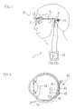
- FIG. 1 is a schematic diagram showing an extracorporeal device 10 of a vision regeneration assisting apparatus 1 according to one embodiment of this invention.
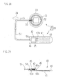
- Figs. 2A and 2B are schematic diagrams showing an intracorporeal device 20 of the apparatus 1
- Fig. 2A is a plan view showing the intracorporeal device 20 as viewed from one side that is opposite to electrode arrangement
- Fig. 2B is a sectional view showing the intracorporeal device 20 as viewed from one side with the side of the electrode arrangement facing in a downward direction.
- the extracorporeal device 10 includes a visor 11 for a patient to wear, an image pickup unit 12 formed of a CCD camera and the like attached to the visor 11, an external unit 13, and a transmitting unit 14 including a primary coil.
- the visor 11 has the shape like glasses and is used as being attached in front of the eyes of the patient.
- the image pickup unit 12 is attached to a front surface of the visor 11 and picks up an object to be visually recognized by the patient.
- the external unit 13 includes a processing unit (signal conversion unit) 13a having an arithmetic processing circuit such as a CPU and a power source unit (battery) 13b for supplying power to the apparatus 1 (extracorporeal device 10 and intracorporeal device 20).
- the processing unit 13a performs image processing of image data obtained by the image pickup unit 12 to convert the image data into electrical stimulation pulse signal data.
- the transmitting unit 14 transmits the electrical stimulation pulse signal data obtained by the conversion and the power (power data) from the power source unit 13b via the processing unit to the intracorporeal device 20 as electromagnetic waves.
- the electromagnetic waves have a frequency of about 16 MHz and are transmitted/received by frequency modulation.
- a magnet (not shown) is attached to be used for improving data transmitting efficiency by the transmitting unit 14 and position fixation of a receiving unit 31 described below.
- the intracorporeal device 20 includes an internal unit 30 for receiving the electrical stimulation pulse signal data and the power transmitted from the extracorporeal device 10 and a stimulation unit 40 for applying electrical stimulation to the cells forming the retina.
- the internal unit 30 includes the receiving unit 31 for receiving the electrical stimulation pulse signal data and the power transmitted from the transmitting unit 14 as the electromagnetic waves and a control unit 32.
- the control unit 32 separates the electromagnetic waves received by the receiving unit 31 into the electrical stimulation pulse signal data and the power and obtains a control signal (electrode assignment signal, etc.) and a parameter signal (intensity signal, etc.) of an electrical stimulation pulse signal based on the electrical stimulation pulse signal data, thereby generating the electrical stimulation pulse signal.
- the receiving unit 31 and the control unit 32 are made from a metal or the like excellent in (having) biocompatibility and disposed on a substrate 33.
- a magnet (not shown) is attached to be used for improving data transmitting efficiency by the receiving unit 31 and position fixation of the transmitting unit 14.
- the stimulation unit 40 includes a plurality of electrodes 41 for outputting the electrical stimulation pulse signal and a control unit 42.
- the control unit 42 distributes the electrical stimulation pulse signals to the electrodes based on the control signal from the control unit 32 to output the electrical stimulation pulse signals to the cells forming the retina.
- the electrical stimulation pulse signals outputted from the electrodes 41 are two-phase (dipolar) pulse signals that are alternating current signals.
- the electrodes 41 are made from a metal excellent in (having) biocompatibility and electroconductivity, such as gold, platinum, titanium nitride, and iridium oxide, and formed (disposed) on a substrate 43.
- the substrate 43 fits to the shape of the eye ball so as to be placed in the eye, particularly in the eye tissue which is in a layered form, the substrate 43 is made from a resin excellent in biocompatibility and capable of being curved at a predetermined thickness, such as polypropylene and polyimide, and has a rectangular shape.
- a thickness of the substrate 43 may preferably be about 50 ⁇ m, so that a certain degree of strength and flexibility are maintained.
- a conductor 43a is formed on (in) the substrate 43, so that the electrodes 41 and the control unit 42 are electrically connected to each other.
- the control unit 42 is disposed on and attached to a base 46 and covered with a cover 45.
- the base 46 is made from a material excellent in (having) biocompatibility, sealing property, and insulating property and has a flat plate-like shape.
- a conductor 46a is formed on (in) the base 46, so that the electrodes 41 (conductor 43a) and the control unit 42 are electrically connected to each other.
- the cover 45 is made from a material excellent in (having) biocompatibility and sealing property and has a box-like shape (hat-like shape), the cover 45 being attached to the base by adhesion, welding, or the like. That is, the control unit 42 is hermetically sealed.
- control unit 32 is also hermetically sealed like the control unit 42.
- the internal unit 30 and the stimulation unit 40 that are disposed at distant positions in the body are connected to each other by a plurality of conductors 50 (conductors 50a to 50d).
- the conductors 50 are made from a metal or the like excellent in (having) biocompatibility and electroconductivity, such as platinum, platiniridium, stainless and titanium.
- the conductors 50 are bundled by a tube 51 made from a resin excellent in (having) biocompatibility and insulating property, such as silicone and perylene, so that handling thereof is easy.
- Each of the conductors 50 is coated with a resin excellent in (having) biocompatibility and insulating property, such as silicone and perylene. Since the signals passing through the conductors 50 are the alternating current signals, it is possible to prevent adverse influence from being exerted on the living body even when the conductors 50 are exposed to and wetted by the bodily fluid.
- Fig. 3 is a schematic block diagram showing an internal structure of the internal unit 30, and Fig. 4 is a schematic block diagram showing an internal structure of the stimulation unit 40.
- the blocks are units formed in a semiconductor integration circuit and execute functions by combinations of various semiconductor elements (transistor such as MOSFET, diode, resistance, condenser, etc.). Description of detailed circuit configuration and the like of each of the blocks is omitted.
- the electromagnetic wave from the extracorporeal device 10 is transmitted as the alternating current signal via the transmitting unit 14 and the receiving unit 31 to a receiving block 61 that is connected to the receiving unit 31.
- the receiving block 61 separates the alternating current signal into the electrical stimulation pulse signal data and the power.
- the separated power is transmitted to a power source block 62 connected to the receiving block 61.
- the power source block 62 converts the power transmitted as the alternating current signal into a direct current by a rectifier 62a and supplies the power of direct current voltage to a decoder 63, an encoder 64, a power supply block 65, and a stimulation block 66.
- the separated electrical stimulation pulse signal data are transmitted to the decoder 63 connected to the receiving block 61.
- the decoder 63 obtains the control signal and the parameter signal of the electrical stimulation pulse signal based on the transmitted electrical stimulation pulse signal data.
- the obtained control signal is transmitted to the encoder 64 connected to the decoder 63.
- the encoder 64 overlaps the transmitted control signal on the alternating current signal by frequency modulation.
- the control signal overlapped on the alternating current signal by the encoder 64 is transmitted to the power supply block 65 connected to the encoder 64.
- the power supply block 64 uses the direct current voltage from the power source block 62 to amplify the alternating current signal on which the control signal is overlapped.
- the obtained parameter signal is transmitted to the stimulation block 66 connected to the decoder 63.
- the stimulation block 66 generates the electrical stimulation pulse signal having predetermined intensity and sustain period based on the parameter signal and the direct current voltage (or current) transmitted from the power source block 62.
- the conductors 50a and 50b which transmit positive and negative signals in alternating current transmission and are paired to each other are connected to the power supply block 65, and the conductors 50c and 50d which transmit positive and negative signals in alternating current transmission and are paired to each other are connected to the stimulation block 66.
- a coupling condenser 52 having a role of a filter for blocking the direct current signals and passing only the alternating current signals is connected to an intermediate point of each of the conductors 50a to 50d.
- the number of each of the conductors 50a to 50b may be two or more.
- a maximum value of a charge amount per half wave of the alternating current signals passing through the conductors 50 (transmitted by the conductors 50) is so set that a charge amount (charge density) per unit area of an exposure part (wetted part) of the conductors 50 is kept to a value that does not cause electrical decomposition of the bodily fluid, and the threshold value of the frequency is set based on the threshold value of the charge amount.
- An amplitude of the frequency of the alternating current signal may preferably be about 20 kHz or more (more preferably about 200 kHz or more) in the case of sine wave since the electrical stimulation pulse signal outputted from the electrodes 41 is from several voltages to several tens of voltages.
- An amplitude of the frequency of the alternating current signal in the case of square wave may preferably be about 40 kHz or more (more preferably about 300 kHz or more) for the same reason.
- the threshold value of the frequency of the alternating current signal is set to a value that keeps noise generated from the intracorporeal device 20 within an acceptable range.
- the conductors 50a, 50b, and 50c are connected to the control unit 42, and the conductor 50d is connected to an opposite electrode 34.
- the conductors 50a and 50b are connected in parallel to a power source block 81 and a decoder 82 of the control unit 42.
- the power source block 81 converts the alternating current signal from the power source block 65 into the direct current signal by a rectifier 81a to supply the power of direct current voltage to the decoder 82 and a multiplexer 83.
- the decoder 82 extracts the control signal from the alternating current signal to transmit the control signal to the multiplexer 83.
- the multiplexer 83 is connected to the decoder 82 and the stimulation block 66 via the conductor 50c and further connected to the electrodes 41 via the conductor 43a.
- the multiplexer 83 distributes the electrical stimulation pulse signal from the stimulation block 66 to the electrodes 41 based on the control signal from the decoder 82.
- the charge amount per half wave of the alternating current signal passing through the conductors 50 and injected from a part at which the conductors 50 are exposed to and contact the bodily fluid will be detected.
- a condition for preventing adverse influence from being exerted on the living body at the contact part of the conductors 50 and the bodily fluid (exposure part of the conductors 50) is such that the charge amount per half wave of the alternating current signal is equal to or less than the maximum value of the charge amount per unit area that does not cause electrical decomposition of the bodily fluid.
- the charge amount is obtained by an experiment and calculation.
- an impedance between the electrode and an opposed electrode having a surface area satisfactorily larger than the electrode dipped into the same normal saline solution is measured.
- the electrode assumed to be the conductors 50 has a diameter of 200 ⁇ m and is made from platinum, and the impedance of the platinum electrode is demodeled by an RC serial circuit (a resistance component of the impedance is R, and a capacitance component of the impedance is C).
- the charge amount per half wave of the alternating current signal is calculated as follows.
- a peak voltage is represented by E
- a cycle is represented by T(1/f)
- time is represented by t
- v E ⁇ sin (2 ⁇ ft) holds in the case of sine wave
- v E holds in the case of square wave.
- the charge amount Q in the case of square wave is as indicated by Expression 2.
- the maximum value of the charge amount per unit area that does not cause electrical decomposition of the bodily fluid when the electrode contacts the bodily fluid is decided depending on the material of the electrode and may preferably be about 400 ⁇ C/cm 2 , more preferably 50 ⁇ C/cm 2 , in the case of the platinum electrode.
- the charge amount per unit area is multiplied by the area of the electrode used in the experiment to be converted into the charge amount, and the frequency f serving as the threshold value is obtained by assigning the charge amount to Expressions 1 and 2.
- the frequency in the case of using platinum as the material for the conductors is calculated as follows.
- the surface area of the electrode having the diameter of 200 ⁇ m is 0.0314 mm 2 (314 x 10 -6 (cm 2 )) by the experiment.
- the resistance component R was 1.5 k ⁇
- the capacitance component C was 22 nF, for example.
- the frequency f achieving the charge amount per unit area of 50 ⁇ C/cm 2 with which the bodily fluid is not electrically decomposed is 200 kHz from Expression 1 in the case of sine wave, and the frequency f in the case of square wave is 307 kHz from Expression 2.
- Fig. 5 is a diagram showing results obtained by assigning the resistance component R and the capacitance component C of the platinum electrode to Expression 1 and Expression 2, wherein a relationship between the characteristic of the platinum electrode and each threshold value of the charge amount and the frequency of the alternating current signal are indicated.
- the maximum value of frequencies when the threshold value of the charge amount per unit area was 50 ⁇ C/cm 2 was 200 kHz in the case of sine wave, and the maximum value of frequencies in the case of square wave was 307 kHz.
- the average value of the frequencies in the case of sine wave was 125 kHz
- the average value of frequencies in the case of square wave was 192 kHz.
- the threshold value of the charge amount per unit area was 400 ⁇ C/cm 2
- the maximum value of the frequencies in the case of sine wave was 25 kHz
- the maximum value of frequencies in the case of square wave was 38 kHz.
- the average value of the frequencies in the case of sine wave was 16 kHz
- the average value of the frequencies in the case of square wave was 24 kHz.
- the frequency threshold values are set appropriately by experiment and the like. For example, the frequency threshold values may be set considering the average values of the frequencies.
- a standard frequency of the alternating current signal is about 1 MHz that is obtained by multiplying the obtained frequency threshold value by a satisfactory factor of safety (e.g. 2 or 3).
- the charge amount per unit area that is considered to be safe for the living bodies means the value at which the bodily fluid is not electrically decomposed.
- the threshold value is not constant and changed depending on the material. In this embodiment, the case of using platinum as the material for the conductors is presumed, and the frequency threshold values were obtained based on the threshold value of the charge amount when platinum is used. However, when the material of the conductor is changed, the threshold value of the charge amount is changed, and the threshold value of the frequency is also changed. In such case, the threshold value of the charge amount may be set depending on the material of the conductors for calculating the threshold value of the frequency.
- the threshold value of the charge amount per unit area of the platinum conductor may preferably be about 400 ⁇ C/cm 2 (more preferably about 50 ⁇ C/cm 2 ), it is considered that a conductor made from an alloy of platinum, such as platinum iridium, has similar tendency (similarity).
- the peak voltage to be applied to the conductors is the fixed value in the above calculations and the like, the peak voltage is not limited to the fixed value. Since the electrical stimulation pulse signal is generated from the alternating current signal of several voltages to several tens of voltages in order to electrically stimulate the cells forming the retina, any value capable of obtaining the alternating current signal of such voltage may be used.
- the charge amount of the alternating current signal, frequency, and the like are set to the values with which the bodily fluid is not electrically decomposed when the conductors are exposed to and wetted by the bodily fluid.
- the control units 32 and 42 may preferably have a monolithic structure.
- the frequency of the alternating current signal passing through the platinum conductors may preferably be about 1 MHz which is about 2 to 3 times of the threshold value of the frequency in order to achieve the frequency appropriate for operation of the control unit 42 having the monolithic structure.
- the frequency of the alternating current signal is low, it is necessary to use a condenser having a large capacity for a rectifying circuit (rectifier 81a) for obtaining stable power in the control unit 42, thereby increasing the size of the control unit 4.
- the frequency is high (for example exceeding 2 MHz), the conductor becomes a noise source.
- Fig. 6 is a diagram showing a state in which the stimulation unit 40 is placed in a body (eye).
- the opposite electrode 34 is placed at a position near the anterior chamber side in the eye, and the electrodes 41 are placed at the chorioid E2 from the sclera E3.
- the retina E1 is defined between the electrodes 41 and the opposite electrode 34, and the electrical stimulation pulse signals from the electrodes 41 efficiently penetrate the retina 1E.
- the internal unit 30 is placed at a predetermined position which is capable of receiving the signal from the transmitting unit 14 in a body of a patient.
- the internal unit 30 is placed under the skin at the temporal part of the patient as shown in Fig. 1 .
- the tube 51 extends from the internal unit 30 toward the eye under the skin of the temporal part to be inserted into the eye hall and passed outside the sclera E3 to be connected to the control unit 42 provided on the substrate 43.
- the position is not limited to the above-described one, and it is possible to place the electrodes at any position capable of electrically stimulating the cells forming the retina.
- the electrodes may be placed on the optic nerve papilla in the eye, the optic nerve outside the eye, or the like.
- the position of the substrate on which the electrodes are formed (disposed) is not limited to the chorioid, and it is possible to appropriately select the position that is reduced in load to be applied to the patient in view of the position at which the electrodes are placed. That is, this invention is applicable to those in which plural units of the intracorporeal device are connected via the conductor.
- the modulation of the alternate current signal was performed by the frequency modulation in this embodiment, the modulation is not limited thereto, and it is possible to perform the modulation by amplification modulation or phase modulation.
- the frequency modulation since amplitude of the alternating current signal is constant, it is possible to obtain substantially constant power when rectification is performed in the intracorporeal device (power source block).
Landscapes
- Health & Medical Sciences (AREA)
- Ophthalmology & Optometry (AREA)
- Engineering & Computer Science (AREA)
- Biomedical Technology (AREA)
- Nuclear Medicine, Radiotherapy & Molecular Imaging (AREA)
- Radiology & Medical Imaging (AREA)
- Life Sciences & Earth Sciences (AREA)
- Animal Behavior & Ethology (AREA)
- General Health & Medical Sciences (AREA)
- Public Health (AREA)
- Veterinary Medicine (AREA)
- Electrotherapy Devices (AREA)
- Prostheses (AREA)
- Materials For Medical Uses (AREA)
Abstract
Description
- This invention relates to a vision regeneration assisting apparatus for regenerating vision of a patient.
- Vision regeneration assisting apparatuses for regenerating lost vision of a blind patient by applying electrical stimulation (electrical stimulation pulse signal) to the cells forming the retina from an electrode placed in the body (eye) of the blind patient have been proposed. Such apparatuses have an extracorporeal device including an image pickup unit and an intracorporeal device including a stimulation unit provided with a multiple of electrodes disposed on a substrate.
- In such apparatuses, various units are provided in the intracorporeal device for outputting the electrical stimulation pulse signal from the electrodes based on electrical stimulation pulse signal data from the extracorporeal device. Since it is preferable to reduce the size and the number of units to be directly placed in the eye of the patient, the units are separately placed at positions distant from one another in the body and electrically connected with one another by a conductor coated with a resin excellent in (having) biocompatibility and insulation property.
However, since the intracorporeal device is placed in the body for a long time, there is a fear that the conductor is exposed to and wetted by the bodily fluid to exert adverse influence on the living body. - A technological object of this invention is to provide a vision regeneration assisting apparatus capable of suppressing adverse influence otherwise exerted on a living body when a conductor electrically connecting units that are placed separately at positions distant from one another in a body is exposed to and wetted by a bodily fluid.
In order to solve the above-described problem, this invention is characterized by having the following structure. -
-
Fig. 1 is a schematic diagram showing an extracorporeal device of a vision regeneration assisting apparatus according to one embodiment of this invention. -
Fig. 2A and Fig. 2B are schematic diagrams showing an intracorporeal device of the vision regeneration assisting apparatus. -
Fig. 3 is a schematic block diagram showing an internal structure of an internal unit. -
Fig. 4 is a schematic block diagram of an internal structure of a stimulation unit. -
Fig. 5 is a diagram showing a relationship between a characteristic of a platinum electrode and each threshold value of a charge amount and a frequency of an alternating current signal. -
Fig. 6 is a diagram showing a state in which the stimulation unit is placed in a body. - This invention will be described based on the drawings.
Fig. 1 is a schematic diagram showing anextracorporeal device 10 of a vision regeneration assisting apparatus 1 according to one embodiment of this invention.Figs. 2A and 2B are schematic diagrams showing anintracorporeal device 20 of the apparatus 1,Fig. 2A is a plan view showing theintracorporeal device 20 as viewed from one side that is opposite to electrode arrangement, andFig. 2B is a sectional view showing theintracorporeal device 20 as viewed from one side with the side of the electrode arrangement facing in a downward direction. - The
extracorporeal device 10 includes avisor 11 for a patient to wear, animage pickup unit 12 formed of a CCD camera and the like attached to thevisor 11, anexternal unit 13, and a transmittingunit 14 including a primary coil.
Thevisor 11 has the shape like glasses and is used as being attached in front of the eyes of the patient.
Theimage pickup unit 12 is attached to a front surface of thevisor 11 and picks up an object to be visually recognized by the patient. - The
external unit 13 includes a processing unit (signal conversion unit) 13a having an arithmetic processing circuit such as a CPU and a power source unit (battery) 13b for supplying power to the apparatus 1 (extracorporeal device 10 and intracorporeal device 20). Theprocessing unit 13a performs image processing of image data obtained by theimage pickup unit 12 to convert the image data into electrical stimulation pulse signal data.
The transmittingunit 14 transmits the electrical stimulation pulse signal data obtained by the conversion and the power (power data) from thepower source unit 13b via the processing unit to theintracorporeal device 20 as electromagnetic waves. The electromagnetic waves have a frequency of about 16 MHz and are transmitted/received by frequency modulation. At the center of the transmittingunit 14, a magnet (not shown) is attached to be used for improving data transmitting efficiency by the transmittingunit 14 and position fixation of areceiving unit 31 described below. - The
intracorporeal device 20 includes aninternal unit 30 for receiving the electrical stimulation pulse signal data and the power transmitted from theextracorporeal device 10 and astimulation unit 40 for applying electrical stimulation to the cells forming the retina.
Theinternal unit 30 includes thereceiving unit 31 for receiving the electrical stimulation pulse signal data and the power transmitted from the transmittingunit 14 as the electromagnetic waves and acontrol unit 32. Thecontrol unit 32 separates the electromagnetic waves received by the receivingunit 31 into the electrical stimulation pulse signal data and the power and obtains a control signal (electrode assignment signal, etc.) and a parameter signal (intensity signal, etc.) of an electrical stimulation pulse signal based on the electrical stimulation pulse signal data, thereby generating the electrical stimulation pulse signal. - The
receiving unit 31 and thecontrol unit 32 are made from a metal or the like excellent in (having) biocompatibility and disposed on asubstrate 33. At the center of the receivingunit 31, a magnet (not shown) is attached to be used for improving data transmitting efficiency by the receivingunit 31 and position fixation of the transmittingunit 14. - The
stimulation unit 40 includes a plurality ofelectrodes 41 for outputting the electrical stimulation pulse signal and acontrol unit 42. Thecontrol unit 42 distributes the electrical stimulation pulse signals to the electrodes based on the control signal from thecontrol unit 32 to output the electrical stimulation pulse signals to the cells forming the retina. The electrical stimulation pulse signals outputted from theelectrodes 41 are two-phase (dipolar) pulse signals that are alternating current signals.
Theelectrodes 41 are made from a metal excellent in (having) biocompatibility and electroconductivity, such as gold, platinum, titanium nitride, and iridium oxide, and formed (disposed) on asubstrate 43. Since it is preferable that thesubstrate 43 fits to the shape of the eye ball so as to be placed in the eye, particularly in the eye tissue which is in a layered form, thesubstrate 43 is made from a resin excellent in biocompatibility and capable of being curved at a predetermined thickness, such as polypropylene and polyimide, and has a rectangular shape. A thickness of thesubstrate 43 may preferably be about 50 µm, so that a certain degree of strength and flexibility are maintained. Aconductor 43a is formed on (in) thesubstrate 43, so that theelectrodes 41 and thecontrol unit 42 are electrically connected to each other. - The
control unit 42 is disposed on and attached to abase 46 and covered with acover 45. Thebase 46 is made from a material excellent in (having) biocompatibility, sealing property, and insulating property and has a flat plate-like shape. Aconductor 46a is formed on (in) thebase 46, so that the electrodes 41 (conductor 43a) and thecontrol unit 42 are electrically connected to each other. Thecover 45 is made from a material excellent in (having) biocompatibility and sealing property and has a box-like shape (hat-like shape), thecover 45 being attached to the base by adhesion, welding, or the like. That is, thecontrol unit 42 is hermetically sealed. - Though not shown, the
control unit 32 is also hermetically sealed like thecontrol unit 42. - [0016] The
internal unit 30 and thestimulation unit 40 that are disposed at distant positions in the body are connected to each other by a plurality of conductors 50 (conductors 50a to 50d). Theconductors 50 are made from a metal or the like excellent in (having) biocompatibility and electroconductivity, such as platinum, platiniridium, stainless and titanium. Theconductors 50 are bundled by atube 51 made from a resin excellent in (having) biocompatibility and insulating property, such as silicone and perylene, so that handling thereof is easy. Each of theconductors 50 is coated with a resin excellent in (having) biocompatibility and insulating property, such as silicone and perylene. Since the signals passing through theconductors 50 are the alternating current signals, it is possible to prevent adverse influence from being exerted on the living body even when theconductors 50 are exposed to and wetted by the bodily fluid. -
Fig. 3 is a schematic block diagram showing an internal structure of theinternal unit 30, andFig. 4 is a schematic block diagram showing an internal structure of thestimulation unit 40. InFigs. 3 and4 , the blocks are units formed in a semiconductor integration circuit and execute functions by combinations of various semiconductor elements (transistor such as MOSFET, diode, resistance, condenser, etc.). Description of detailed circuit configuration and the like of each of the blocks is omitted. - The electromagnetic wave from the
extracorporeal device 10 is transmitted as the alternating current signal via the transmittingunit 14 and thereceiving unit 31 to areceiving block 61 that is connected to thereceiving unit 31. Thereceiving block 61 separates the alternating current signal into the electrical stimulation pulse signal data and the power. - The separated power is transmitted to a power source block 62 connected to the receiving
block 61. The power source block 62 converts the power transmitted as the alternating current signal into a direct current by arectifier 62a and supplies the power of direct current voltage to adecoder 63, anencoder 64, apower supply block 65, and astimulation block 66. The separated electrical stimulation pulse signal data are transmitted to thedecoder 63 connected to the receivingblock 61. Thedecoder 63 obtains the control signal and the parameter signal of the electrical stimulation pulse signal based on the transmitted electrical stimulation pulse signal data. - The obtained control signal is transmitted to the
encoder 64 connected to thedecoder 63. Theencoder 64 overlaps the transmitted control signal on the alternating current signal by frequency modulation. The control signal overlapped on the alternating current signal by theencoder 64 is transmitted to thepower supply block 65 connected to theencoder 64. Thepower supply block 64 uses the direct current voltage from thepower source block 62 to amplify the alternating current signal on which the control signal is overlapped. - In turn, the obtained parameter signal is transmitted to the
stimulation block 66 connected to thedecoder 63. Thestimulation block 66 generates the electrical stimulation pulse signal having predetermined intensity and sustain period based on the parameter signal and the direct current voltage (or current) transmitted from thepower source block 62. - The
conductors power supply block 65, and theconductors stimulation block 66. Acoupling condenser 52 having a role of a filter for blocking the direct current signals and passing only the alternating current signals is connected to an intermediate point of each of theconductors 50a to 50d. The number of each of theconductors 50a to 50b may be two or more.
In order to prevent adverse influence from being exerted on the living body even when theconductors 50 are exposed to and wetted by the bodily fluid, a maximum value of a charge amount per half wave of the alternating current signals passing through the conductors 50 (transmitted by the conductors 50) is so set that a charge amount (charge density) per unit area of an exposure part (wetted part) of theconductors 50 is kept to a value that does not cause electrical decomposition of the bodily fluid, and the threshold value of the frequency is set based on the threshold value of the charge amount. An amplitude of the frequency of the alternating current signal may preferably be about 20 kHz or more (more preferably about 200 kHz or more) in the case of sine wave since the electrical stimulation pulse signal outputted from theelectrodes 41 is from several voltages to several tens of voltages. An amplitude of the frequency of the alternating current signal in the case of square wave may preferably be about 40 kHz or more (more preferably about 300 kHz or more) for the same reason. Also, the threshold value of the frequency of the alternating current signal is set to a value that keeps noise generated from theintracorporeal device 20 within an acceptable range. - The
conductors control unit 42, and theconductor 50d is connected to anopposite electrode 34. Theconductors power source block 81 and adecoder 82 of thecontrol unit 42. The power source block 81 converts the alternating current signal from thepower source block 65 into the direct current signal by arectifier 81a to supply the power of direct current voltage to thedecoder 82 and amultiplexer 83. Thedecoder 82 extracts the control signal from the alternating current signal to transmit the control signal to themultiplexer 83. - The
multiplexer 83 is connected to thedecoder 82 and thestimulation block 66 via theconductor 50c and further connected to theelectrodes 41 via theconductor 43a. Themultiplexer 83 distributes the electrical stimulation pulse signal from thestimulation block 66 to theelectrodes 41 based on the control signal from thedecoder 82. - Hereinafter, a method for deciding each threshold value of the charge amount per half wave and the frequency of the alternating current signal that do not cause adverse influence to be exerted on the living body, i.e. do not cause the bodily fluid to be electrically decomposed at an exposure part (wetted part) of the
conductors 50, according to this embodiment will be described. - The charge amount per half wave of the alternating current signal passing through the
conductors 50 and injected from a part at which theconductors 50 are exposed to and contact the bodily fluid will be detected. A condition for preventing adverse influence from being exerted on the living body at the contact part of theconductors 50 and the bodily fluid (exposure part of the conductors 50) is such that the charge amount per half wave of the alternating current signal is equal to or less than the maximum value of the charge amount per unit area that does not cause electrical decomposition of the bodily fluid. The charge amount is obtained by an experiment and calculation. - As the experiment, in a state where an electrode having a certain surface area and made from the material same as that of the
conductors 50 is dipped into a normal saline solution similar to the bodily fluid, an impedance between the electrode and an opposed electrode having a surface area satisfactorily larger than the electrode dipped into the same normal saline solution is measured. The electrode assumed to be theconductors 50 has a diameter of 200 µm and is made from platinum, and the impedance of the platinum electrode is demodeled by an RC serial circuit (a resistance component of the impedance is R, and a capacitance component of the impedance is C). - The charge amount per half wave of the alternating current signal is calculated as follows. When the frequency of the output voltage v of the
power supply block 65 is represented by f, a peak voltage is represented by E, and a cycle is represented by T(1/f), and time is represented by t, v = E·sin (2πft) holds in the case of sine wave, and v = E holds in the case of square wave. - Accordingly, the charge amount Q per half wave (t = 0 to T/2) when the current is represented by i in the case of sine wave is as indicated by Expression 1, and the charge amount Q in the case of square wave is as indicated by
Expression 2. -

-

FromExpressions 1 and 2, it is apparent that the charge amount Q tends to be decreased in accordance with an increase in frequency f in the case where the peak voltage E is a fixed value. - In general, the maximum value of the charge amount per unit area that does not cause electrical decomposition of the bodily fluid when the electrode contacts the bodily fluid is decided depending on the material of the electrode and may preferably be about 400 µC/cm2, more preferably 50 µC/cm2, in the case of the platinum electrode. The charge amount per unit area is multiplied by the area of the electrode used in the experiment to be converted into the charge amount, and the frequency f serving as the threshold value is obtained by assigning the charge amount to
Expressions 1 and 2. - By the above calculations, the frequency in the case of using platinum as the material for the conductors is calculated as follows.
- The surface area of the electrode having the diameter of 200 µm is 0.0314 mm2 (314 x 10-6(cm2)) by the experiment. With the impedance of the platinum electrode, the resistance component R was 1.5 kΩ, and the capacitance component C was 22 nF, for example. When the peak voltage E to be applied to the conductors is 15 V, the frequency f achieving the charge amount per unit area of 50 µC/cm2 with which the bodily fluid is not electrically decomposed is 200 kHz from Expression 1 in the case of sine wave, and the frequency f in the case of square wave is 307 kHz from
Expression 2. -
Fig. 5 is a diagram showing results obtained by assigning the resistance component R and the capacitance component C of the platinum electrode to Expression 1 andExpression 2, wherein a relationship between the characteristic of the platinum electrode and each threshold value of the charge amount and the frequency of the alternating current signal are indicated. In the twelve platinum electrodes, the maximum value of frequencies when the threshold value of the charge amount per unit area was 50 µC/cm2 was 200 kHz in the case of sine wave, and the maximum value of frequencies in the case of square wave was 307 kHz. Also, the average value of the frequencies in the case of sine wave was 125 kHz, and the average value of frequencies in the case of square wave was 192 kHz. Likewise, when the threshold value of the charge amount per unit area was 400 µC/cm2, the maximum value of the frequencies in the case of sine wave was 25 kHz, and the maximum value of frequencies in the case of square wave was 38 kHz. The average value of the frequencies in the case of sine wave was 16 kHz, and the average value of the frequencies in the case of square wave was 24 kHz. - Consequently, when the frequency equal to or more than the threshold value is set to the lowest frequency of the alternating current signal (the lowest frequency in the case of frequency modulation), it is considered that the bodily fluid is not electrically decomposed even when the
conductors 50 are exposed to and wetted by the bodily fluid. The frequency threshold values are set appropriately by experiment and the like. For example, the frequency threshold values may be set considering the average values of the frequencies. - In this embodiment, a standard frequency of the alternating current signal is about 1 MHz that is obtained by multiplying the obtained frequency threshold value by a satisfactory factor of safety (e.g. 2 or 3).
- The charge amount per unit area that is considered to be safe for the living bodies means the value at which the bodily fluid is not electrically decomposed. The threshold value is not constant and changed depending on the material. In this embodiment, the case of using platinum as the material for the conductors is presumed, and the frequency threshold values were obtained based on the threshold value of the charge amount when platinum is used. However, when the material of the conductor is changed, the threshold value of the charge amount is changed, and the threshold value of the frequency is also changed. In such case, the threshold value of the charge amount may be set depending on the material of the conductors for calculating the threshold value of the frequency. Also, though the threshold value of the charge amount per unit area of the platinum conductor may preferably be about 400 µC/cm2 (more preferably about 50 µC/cm2), it is considered that a conductor made from an alloy of platinum, such as platinum iridium, has similar tendency (similarity).
- Also, though the peak voltage to be applied to the conductors is the fixed value in the above calculations and the like, the peak voltage is not limited to the fixed value. Since the electrical stimulation pulse signal is generated from the alternating current signal of several voltages to several tens of voltages in order to electrically stimulate the cells forming the retina, any value capable of obtaining the alternating current signal of such voltage may be used. The charge amount of the alternating current signal, frequency, and the like are set to the values with which the bodily fluid is not electrically decomposed when the conductors are exposed to and wetted by the bodily fluid.
- In order to reduce the size of the
intracorporeal device 20, thecontrol units control unit 42 having the monolithic structure. When the frequency of the alternating current signal is low, it is necessary to use a condenser having a large capacity for a rectifying circuit (rectifier 81a) for obtaining stable power in thecontrol unit 42, thereby increasing the size of thecontrol unit 4. Also, when the frequency is high (for example exceeding 2 MHz), the conductor becomes a noise source. -
Fig. 6 is a diagram showing a state in which thestimulation unit 40 is placed in a body (eye). Theopposite electrode 34 is placed at a position near the anterior chamber side in the eye, and theelectrodes 41 are placed at the chorioid E2 from the sclera E3. With such constitution, the retina E1 is defined between theelectrodes 41 and theopposite electrode 34, and the electrical stimulation pulse signals from theelectrodes 41 efficiently penetrate the retina 1E. - The
internal unit 30 is placed at a predetermined position which is capable of receiving the signal from the transmittingunit 14 in a body of a patient. For example, theinternal unit 30 is placed under the skin at the temporal part of the patient as shown inFig. 1 . - The
tube 51 extends from theinternal unit 30 toward the eye under the skin of the temporal part to be inserted into the eye hall and passed outside the sclera E3 to be connected to thecontrol unit 42 provided on thesubstrate 43. - Though the electrodes are placed at the chorioid from the sclera side in this embodiment, the position is not limited to the above-described one, and it is possible to place the electrodes at any position capable of electrically stimulating the cells forming the retina. Also, the electrodes may be placed on the optic nerve papilla in the eye, the optic nerve outside the eye, or the like. The position of the substrate on which the electrodes are formed (disposed) is not limited to the chorioid, and it is possible to appropriately select the position that is reduced in load to be applied to the patient in view of the position at which the electrodes are placed. That is, this invention is applicable to those in which plural units of the intracorporeal device are connected via the conductor.
- Though the modulation of the alternate current signal was performed by the frequency modulation in this embodiment, the modulation is not limited thereto, and it is possible to perform the modulation by amplification modulation or phase modulation. In the case of the frequency modulation, since amplitude of the alternating current signal is constant, it is possible to obtain substantially constant power when rectification is performed in the intracorporeal device (power source block).
Claims (5)
- A vision regeneration assisting apparatus for regenerating vision of a patient, comprising:an extracorporeal device and an intracorporeal device,wherein the extracorporeal device includes
an image pickup unit,
a processing unit that converts image data obtained by the image pickup into electrical stimulation pulse signal data, and
a transmitting unit that converts the electrical stimulation pulse signal data and power into a predetermined signal and transmitting the signal, andwherein the intracorporeal device includes
a receiving unit that receives the signal transmitted from the transmitting unit,
a first control unit that extracts the electrical stimulation pulse signal data and the power from the signal received by the receiving unit to convert the electrical stimulation pulse signal data and the power into a predetermined alternating current signal,
a second control unit that is provided separately at a position distant from the first control unit and outputs an electrical stimulation pulse signal from a plurality of electrodes based on the alternating current signal from the first control unit, and
a conductor that is covered with a resin having biocompatibility and insulating property and electrically connects the first control unit and the second control unit to each other to send the alternating current signal. - The vision regeneration assisting apparatus according to claim 1, wherein a charge amount per half wave of the alternating current signals is set so that, when the conductor is exposed and wetted by bodily fluid, a charge amount per unit area discharged from the conductor does not cause electrical decomposition of the bodily fluid.
- The vision regeneration assisting apparatus according to claim 1 or 2,
wherein the conductor being made from platinum or a platinum alloy, and
wherein a charge amount per half wave of the alternating current signals is set so that, when the conductor is exposed and wetted by bodily fluid, a charge amount per unit area discharged from the conductor is 400 µC/cm2 or less. - The vision regeneration assisting apparatus according to claim 3, wherein the charge amount per half wave of the alternating current signals is set so that, when the conductor is exposed and wetted by the bodily fluid, the charge amount per unit area discharged from the conductor is 50 µC/cm2 or less.
- The vision regeneration assisting apparatus according to any one of claims 1 to 4, wherein the first control unit generates the electrical stimulation pulse signal based on the extracted electrical stimulation pulse signal data and converts the generated electrical stimulation pulse signal and the power into alternating current signals.
Applications Claiming Priority (1)
| Application Number | Priority Date | Filing Date | Title |
|---|---|---|---|
| JP2007020117A JP4970069B2 (en) | 2007-01-30 | 2007-01-30 | Visual reproduction assist device |
Publications (2)
| Publication Number | Publication Date |
|---|---|
| EP1958661A1 true EP1958661A1 (en) | 2008-08-20 |
| EP1958661B1 EP1958661B1 (en) | 2015-03-11 |
Family
ID=39327233
Family Applications (1)
| Application Number | Title | Priority Date | Filing Date |
|---|---|---|---|
| EP08001725.4A Ceased EP1958661B1 (en) | 2007-01-30 | 2008-01-30 | Vision regeneration assisting apparatus |
Country Status (3)
| Country | Link |
|---|---|
| US (1) | US7941222B2 (en) |
| EP (1) | EP1958661B1 (en) |
| JP (1) | JP4970069B2 (en) |
Cited By (14)
| Publication number | Priority date | Publication date | Assignee | Title |
|---|---|---|---|---|
| CN102793592A (en) * | 2012-08-09 | 2012-11-28 | 上海交通大学 | Optic nerve implantable neural interface device with fan-shaped attaching function |
| US9265956B2 (en) | 2013-03-08 | 2016-02-23 | Oculeve, Inc. | Devices and methods for treating dry eye in animals |
| US9440065B2 (en) | 2013-04-19 | 2016-09-13 | Oculeve, Inc. | Nasal stimulation devices and methods |
| US9687652B2 (en) | 2014-07-25 | 2017-06-27 | Oculeve, Inc. | Stimulation patterns for treating dry eye |
| US9717627B2 (en) | 2013-03-12 | 2017-08-01 | Oculeve, Inc. | Implant delivery devices, systems, and methods |
| US9737712B2 (en) | 2014-10-22 | 2017-08-22 | Oculeve, Inc. | Stimulation devices and methods for treating dry eye |
| US9764150B2 (en) | 2014-10-22 | 2017-09-19 | Oculeve, Inc. | Contact lens for increasing tear production |
| US9770583B2 (en) | 2014-02-25 | 2017-09-26 | Oculeve, Inc. | Polymer formulations for nasolacrimal stimulation |
| US9821159B2 (en) | 2010-11-16 | 2017-11-21 | The Board Of Trustees Of The Leland Stanford Junior University | Stimulation devices and methods |
| US10207108B2 (en) | 2014-10-22 | 2019-02-19 | Oculeve, Inc. | Implantable nasal stimulator systems and methods |
| US10252048B2 (en) | 2016-02-19 | 2019-04-09 | Oculeve, Inc. | Nasal stimulation for rhinitis, nasal congestion, and ocular allergies |
| US10426958B2 (en) | 2015-12-04 | 2019-10-01 | Oculeve, Inc. | Intranasal stimulation for enhanced release of ocular mucins and other tear proteins |
| US10610095B2 (en) | 2016-12-02 | 2020-04-07 | Oculeve, Inc. | Apparatus and method for dry eye forecast and treatment recommendation |
| US10918864B2 (en) | 2016-05-02 | 2021-02-16 | Oculeve, Inc. | Intranasal stimulation for treatment of meibomian gland disease and blepharitis |
Families Citing this family (8)
| Publication number | Priority date | Publication date | Assignee | Title |
|---|---|---|---|---|
| JP5284014B2 (en) * | 2008-09-02 | 2013-09-11 | 株式会社ニデック | Visual reproduction assist device |
| JP5405848B2 (en) * | 2009-02-16 | 2014-02-05 | 株式会社ニデック | Visual reproduction assist device |
| US20100268309A1 (en) * | 2009-04-17 | 2010-10-21 | Boston Scientific Neuromodulation Corporation | Architectures for Multi-Electrode Implantable Stimulator Devices Having Minimal Numbers of Decoupling Capacitors |
| JP5545962B2 (en) * | 2010-02-16 | 2014-07-09 | 株式会社ニデック | Visual reproduction assist device |
| CA2817589A1 (en) | 2010-11-16 | 2012-05-24 | The Board Of Trustees Of The Leland Stanford Junior University | Systems and methods for treatment of dry eye |
| CN104225785B (en) * | 2013-06-20 | 2018-11-16 | 苏州六六视觉科技股份有限公司 | For treating the therapeutic device of visual system disease |
| CN103816006B (en) * | 2014-02-20 | 2016-01-20 | 深圳市上示科技有限公司 | The equipment that a kind of non-implantable excites blind visual to experience through body surface |
| US11338139B2 (en) * | 2018-10-01 | 2022-05-24 | Biovisics Medical, Inc. | System and methods for controlled electrical modulation for vision therapy |
Citations (5)
| Publication number | Priority date | Publication date | Assignee | Title |
|---|---|---|---|---|
| WO2000006248A1 (en) * | 1998-07-27 | 2000-02-10 | Mortimer J Thomas | Device and method for production of visual sensations by optic nerve stimulation |
| US20020038134A1 (en) * | 1999-03-24 | 2002-03-28 | Greenberg Robert J. | Package for an implantable medical device |
| EP1386636A2 (en) * | 2002-07-31 | 2004-02-04 | Nidek Co., Ltd | Visual restoration aiding device |
| US20060036295A1 (en) * | 2004-05-25 | 2006-02-16 | Robert Greenberg | Retinal prosthesis |
| US20060287688A1 (en) * | 2005-03-31 | 2006-12-21 | Nidek Co., Ltd. | Vision regeneration assisting apparatus |
Family Cites Families (7)
| Publication number | Priority date | Publication date | Assignee | Title |
|---|---|---|---|---|
| UA78672C2 (en) * | 1999-04-09 | 2007-04-25 | Kevin R Orton | Method for preparation and use of conductive medicinal substance (variants) |
| JP4781576B2 (en) * | 2001-02-28 | 2011-09-28 | 株式会社ニデック | Implantable visual stimulator |
| US6920361B2 (en) * | 2003-02-14 | 2005-07-19 | Medtronic, Inc. | Reverse wound electrodes |
| TW200531716A (en) * | 2004-03-19 | 2005-10-01 | Skylark Device & Systems Co Ltd | Method and apparatus for applying microcurrent into eyes |
| JP4546184B2 (en) | 2004-08-04 | 2010-09-15 | 株式会社ニデック | Rectification circuit and visual reproduction assisting device having the same |
| JP2006280412A (en) | 2005-03-31 | 2006-10-19 | Nidek Co Ltd | Auxiliary device for regenerating visual sense and method of manufacturing |
| JP2007044323A (en) | 2005-08-11 | 2007-02-22 | Nidek Co Ltd | Eyesight regeneration supporting apparatus |
-
2007
- 2007-01-30 JP JP2007020117A patent/JP4970069B2/en not_active Expired - Fee Related
-
2008
- 2008-01-30 EP EP08001725.4A patent/EP1958661B1/en not_active Ceased
- 2008-01-30 US US12/022,374 patent/US7941222B2/en not_active Expired - Fee Related
Patent Citations (5)
| Publication number | Priority date | Publication date | Assignee | Title |
|---|---|---|---|---|
| WO2000006248A1 (en) * | 1998-07-27 | 2000-02-10 | Mortimer J Thomas | Device and method for production of visual sensations by optic nerve stimulation |
| US20020038134A1 (en) * | 1999-03-24 | 2002-03-28 | Greenberg Robert J. | Package for an implantable medical device |
| EP1386636A2 (en) * | 2002-07-31 | 2004-02-04 | Nidek Co., Ltd | Visual restoration aiding device |
| US20060036295A1 (en) * | 2004-05-25 | 2006-02-16 | Robert Greenberg | Retinal prosthesis |
| US20060287688A1 (en) * | 2005-03-31 | 2006-12-21 | Nidek Co., Ltd. | Vision regeneration assisting apparatus |
Cited By (30)
| Publication number | Priority date | Publication date | Assignee | Title |
|---|---|---|---|---|
| US9821159B2 (en) | 2010-11-16 | 2017-11-21 | The Board Of Trustees Of The Leland Stanford Junior University | Stimulation devices and methods |
| US10328262B2 (en) | 2010-11-16 | 2019-06-25 | The Board Of Trustees Of The Leland Stanford Junior University | Stimulation devices and methods |
| US10835748B2 (en) | 2010-11-16 | 2020-11-17 | Oculeve, Inc. | Stimulation devices and methods |
| CN102793592A (en) * | 2012-08-09 | 2012-11-28 | 上海交通大学 | Optic nerve implantable neural interface device with fan-shaped attaching function |
| US9265956B2 (en) | 2013-03-08 | 2016-02-23 | Oculeve, Inc. | Devices and methods for treating dry eye in animals |
| US9717627B2 (en) | 2013-03-12 | 2017-08-01 | Oculeve, Inc. | Implant delivery devices, systems, and methods |
| US10537469B2 (en) | 2013-03-12 | 2020-01-21 | Oculeve, Inc. | Implant delivery devices, systems, and methods |
| US10155108B2 (en) | 2013-04-19 | 2018-12-18 | Oculeve, Inc. | Nasal stimulation devices and methods |
| US10835738B2 (en) | 2013-04-19 | 2020-11-17 | Oculeve, Inc. | Nasal stimulation devices and methods |
| US9737702B2 (en) | 2013-04-19 | 2017-08-22 | Oculeve, Inc. | Nasal stimulation devices and methods |
| US10799695B2 (en) | 2013-04-19 | 2020-10-13 | Oculeve, Inc. | Nasal stimulation devices and methods |
| US10238861B2 (en) | 2013-04-19 | 2019-03-26 | Oculeve, Inc. | Nasal stimulation devices and methods for treating dry eye |
| US10967173B2 (en) | 2013-04-19 | 2021-04-06 | Oculeve, Inc. | Nasal stimulation devices and methods for treating dry eye |
| US9440065B2 (en) | 2013-04-19 | 2016-09-13 | Oculeve, Inc. | Nasal stimulation devices and methods |
| US9770583B2 (en) | 2014-02-25 | 2017-09-26 | Oculeve, Inc. | Polymer formulations for nasolacrimal stimulation |
| US9956397B2 (en) | 2014-02-25 | 2018-05-01 | Oculeve, Inc. | Polymer Formulations for nasolacrimal stimulation |
| US10799696B2 (en) | 2014-02-25 | 2020-10-13 | Oculeve, Inc. | Polymer formulations for nasolacrimal stimulation |
| US10722713B2 (en) | 2014-07-25 | 2020-07-28 | Oculeve, Inc. | Stimulation patterns for treating dry eye |
| US9687652B2 (en) | 2014-07-25 | 2017-06-27 | Oculeve, Inc. | Stimulation patterns for treating dry eye |
| US10610695B2 (en) | 2014-10-22 | 2020-04-07 | Oculeve, Inc. | Implantable device for increasing tear production |
| US10780273B2 (en) | 2014-10-22 | 2020-09-22 | Oculeve, Inc. | Stimulation devices and methods for treating dry eye |
| US10207108B2 (en) | 2014-10-22 | 2019-02-19 | Oculeve, Inc. | Implantable nasal stimulator systems and methods |
| US10112048B2 (en) | 2014-10-22 | 2018-10-30 | Oculeve, Inc. | Stimulation devices and methods for treating dry eye |
| US9764150B2 (en) | 2014-10-22 | 2017-09-19 | Oculeve, Inc. | Contact lens for increasing tear production |
| US9737712B2 (en) | 2014-10-22 | 2017-08-22 | Oculeve, Inc. | Stimulation devices and methods for treating dry eye |
| US10426958B2 (en) | 2015-12-04 | 2019-10-01 | Oculeve, Inc. | Intranasal stimulation for enhanced release of ocular mucins and other tear proteins |
| US10252048B2 (en) | 2016-02-19 | 2019-04-09 | Oculeve, Inc. | Nasal stimulation for rhinitis, nasal congestion, and ocular allergies |
| US10940310B2 (en) | 2016-02-19 | 2021-03-09 | Oculeve, Inc. | Nasal stimulation for rhinitis, nasal congestion, and ocular allergies |
| US10918864B2 (en) | 2016-05-02 | 2021-02-16 | Oculeve, Inc. | Intranasal stimulation for treatment of meibomian gland disease and blepharitis |
| US10610095B2 (en) | 2016-12-02 | 2020-04-07 | Oculeve, Inc. | Apparatus and method for dry eye forecast and treatment recommendation |
Also Published As
| Publication number | Publication date |
|---|---|
| US7941222B2 (en) | 2011-05-10 |
| EP1958661B1 (en) | 2015-03-11 |
| JP4970069B2 (en) | 2012-07-04 |
| JP2008183248A (en) | 2008-08-14 |
| US20080183243A1 (en) | 2008-07-31 |
Similar Documents
| Publication | Publication Date | Title |
|---|---|---|
| EP1958661B1 (en) | Vision regeneration assisting apparatus | |
| US11712572B2 (en) | Implantable wireless acoustic stimulators with high energy conversion efficiencies | |
| US11400318B2 (en) | Apparatus, system, and method for neurostimulation by high frequency ultrasound | |
| EP2544761B1 (en) | Operation and estimation of output voltage of wireless stimulators | |
| Johnson et al. | StimDust: A 6.5 mm 3, wireless ultrasonic peripheral nerve stimulator with 82% peak chip efficiency | |
| US11179568B2 (en) | Controlling charge flow in the electrical stimulation of tissue | |
| US10022566B2 (en) | Apparatus, systems, and methods for current monitoring in ultrasound powered neurostimulation | |
| US20150148863A1 (en) | Brain stimulating system | |
| CN108837305B (en) | Flexible pacemaker and bioelectricity monitoring method based on flexible pacemaker | |
| CN115445083B (en) | Electrical stimulator and electrical neutralization protection method of electrical stimulator | |
| US20230074017A1 (en) | Electrical stimulation device and electrical stimulation system | |
| US12465773B2 (en) | Implantable electronic devices | |
| JP4767571B2 (en) | Visual reproduction assist device | |
| CN114401684A (en) | Bone stimulator and bone stimulation system for fracture healing | |
| US20230075750A1 (en) | Electrical stimulation device and electrical stimulation system | |
| US20250242154A1 (en) | Device and Method for Delivery of Transcutaneous Current | |
| JP2020081720A (en) | Visual sensation regeneration aid apparatus | |
| HK40073537A (en) | Bone stimulator and bone stimulation system for bone fracture healing | |
| HK1018225A (en) | A pulse beauty apparatus using plane electrodes | |
| JP2008245834A (en) | Vision regeneration assisting device, and conducting wire connecting method of vision regeneration assisting device |
Legal Events
| Date | Code | Title | Description |
|---|---|---|---|
| PUAI | Public reference made under article 153(3) epc to a published international application that has entered the european phase |
Free format text: ORIGINAL CODE: 0009012 |
|
| AK | Designated contracting states |
Kind code of ref document: A1 Designated state(s): AT BE BG CH CY CZ DE DK EE ES FI FR GB GR HR HU IE IS IT LI LT LU LV MC MT NL NO PL PT RO SE SI SK TR |
|
| AX | Request for extension of the european patent |
Extension state: AL BA MK RS |
|
| 17P | Request for examination filed |
Effective date: 20090217 |
|
| AKX | Designation fees paid |
Designated state(s): DE FR GB |
|
| 17Q | First examination report despatched |
Effective date: 20110217 |
|
| GRAJ | Information related to disapproval of communication of intention to grant by the applicant or resumption of examination proceedings by the epo deleted |
Free format text: ORIGINAL CODE: EPIDOSDIGR1 |
|
| GRAP | Despatch of communication of intention to grant a patent |
Free format text: ORIGINAL CODE: EPIDOSNIGR1 |
|
| INTG | Intention to grant announced |
Effective date: 20140915 |
|
| GRAS | Grant fee paid |
Free format text: ORIGINAL CODE: EPIDOSNIGR3 |
|
| GRAA | (expected) grant |
Free format text: ORIGINAL CODE: 0009210 |
|
| AK | Designated contracting states |
Kind code of ref document: B1 Designated state(s): DE FR GB |
|
| REG | Reference to a national code |
Ref country code: GB Ref legal event code: FG4D |
|
| REG | Reference to a national code |
Ref country code: DE Ref legal event code: R096 Ref document number: 602008037062 Country of ref document: DE Effective date: 20150423 |
|
| REG | Reference to a national code |
Ref country code: FR Ref legal event code: PLFP Year of fee payment: 9 |
|
| REG | Reference to a national code |
Ref country code: DE Ref legal event code: R097 Ref document number: 602008037062 Country of ref document: DE |
|
| PLBE | No opposition filed within time limit |
Free format text: ORIGINAL CODE: 0009261 |
|
| STAA | Information on the status of an ep patent application or granted ep patent |
Free format text: STATUS: NO OPPOSITION FILED WITHIN TIME LIMIT |
|
| 26N | No opposition filed |
Effective date: 20151214 |
|
| PGFP | Annual fee paid to national office [announced via postgrant information from national office to epo] |
Ref country code: GB Payment date: 20160127 Year of fee payment: 9 |
|
| REG | Reference to a national code |
Ref country code: FR Ref legal event code: PLFP Year of fee payment: 10 |
|
| GBPC | Gb: european patent ceased through non-payment of renewal fee |
Effective date: 20170130 |
|
| PG25 | Lapsed in a contracting state [announced via postgrant information from national office to epo] |
Ref country code: GB Free format text: LAPSE BECAUSE OF NON-PAYMENT OF DUE FEES Effective date: 20170130 |
|
| REG | Reference to a national code |
Ref country code: FR Ref legal event code: PLFP Year of fee payment: 11 |
|
| PGFP | Annual fee paid to national office [announced via postgrant information from national office to epo] |
Ref country code: FR Payment date: 20181213 Year of fee payment: 12 |
|
| PGFP | Annual fee paid to national office [announced via postgrant information from national office to epo] |
Ref country code: DE Payment date: 20190115 Year of fee payment: 12 |
|
| REG | Reference to a national code |
Ref country code: DE Ref legal event code: R119 Ref document number: 602008037062 Country of ref document: DE |
|
| PG25 | Lapsed in a contracting state [announced via postgrant information from national office to epo] |
Ref country code: FR Free format text: LAPSE BECAUSE OF NON-PAYMENT OF DUE FEES Effective date: 20200131 Ref country code: DE Free format text: LAPSE BECAUSE OF NON-PAYMENT OF DUE FEES Effective date: 20200801 |