EP1958491A1 - Height of cut adjustment system for reel mower - Google Patents
Height of cut adjustment system for reel mower Download PDFInfo
- Publication number
- EP1958491A1 EP1958491A1 EP08101154A EP08101154A EP1958491A1 EP 1958491 A1 EP1958491 A1 EP 1958491A1 EP 08101154 A EP08101154 A EP 08101154A EP 08101154 A EP08101154 A EP 08101154A EP 1958491 A1 EP1958491 A1 EP 1958491A1
- Authority
- EP
- European Patent Office
- Prior art keywords
- adjustment
- height
- cut
- cutting unit
- adjustment system
- Prior art date
- Legal status (The legal status is an assumption and is not a legal conclusion. Google has not performed a legal analysis and makes no representation as to the accuracy of the status listed.)
- Granted
Links
Images

Classifications
-
- A—HUMAN NECESSITIES
- A01—AGRICULTURE; FORESTRY; ANIMAL HUSBANDRY; HUNTING; TRAPPING; FISHING
- A01D—HARVESTING; MOWING
- A01D34/00—Mowers; Mowing apparatus of harvesters
- A01D34/01—Mowers; Mowing apparatus of harvesters characterised by features relating to the type of cutting apparatus
- A01D34/412—Mowers; Mowing apparatus of harvesters characterised by features relating to the type of cutting apparatus having rotating cutters
- A01D34/42—Mowers; Mowing apparatus of harvesters characterised by features relating to the type of cutting apparatus having rotating cutters having cutters rotating about a horizontal axis, e.g. cutting-cylinders
- A01D34/54—Cutting-height adjustment
Definitions
- This invention relates generally to a height of cut adjustment system for a reel type grass cutting unit.
- Reel type grass cutting units typically used on golf courses and athletic fields are designed so the height at which the grass is cut can be adjusted to various levels as desired. This is an important adjustment because the appearance and health of the turf, and the quality of the athletic activity may be affected by the cut height. Throughout the growing season, the cut height may need to be changed to suit the growing conditions. Additionally, the cut height may need to be changed for different areas. On a golf course, for example, areas such as fairways are usually cut at different heights than roughs or approaches.
- a self-adjusting reel type grass cutting unit has been developed that sets the cut height automatically when commanded through a user interface.
- This adjustment system has two separate frameworks: the cutting unit frame and the ground contacting frame.
- a pair of adjusting screws actuated by dc electric motors may raise and lower the cutting unit frame with respect to the ground contacting frame.
- a four bar linkage on each end of the cutting unit frame sets the attitude of the cutting unit frame and keeps the cutting unit frame approximately parallel with the ground as the cut height is adjusted.
- a self adjusting reel is shown in US Patent No. 7,114,318 assigned to Deere & Company of Moline, Illinois.
- the self adjusting reel described above has many advantages over manually adjusting the height of cut, including savings in time, skill and effort required to make the adjustment, and high accuracy. It would be desirable to further reduce the work required to set or change the height of cut of a reel type grass cutting unit.
- a height of cut adjustment system for a reel type grass cutting unit includes independent adjustment mechanisms mounted to each corner of a frame of the cutting unit. Each independent adjustment mechanism operates to raise and lower a vertical post supporting a corner of the cutting unit. Linkages between the independent adjustment mechanisms allow the posts to be raised or lowered synchronously to set the cutting height. The height of cut can be set or changed from a single adjustment point.
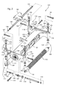
- Figs. 1-3 show a height of cut adjustment system 101 for a reel type grass cutting unit according to a first embodiment of the invention.
- the reel type grass cutting unit has a horizontal shaft 102 that rotates to turn cutting reel 103, to cut grass between the cutting reel and bed knife 104.
- Motor 105 may be used to rotate shaft 102, and may be electric or hydraulic.
- height of cut adjustment system 101 includes four independent adjustment mechanisms, each of which may be rigidly attached to and support a corner of cutting unit frame 106.
- the independent adjustment mechanisms may be adjustment screw mechanisms 108-11.
- Front ground roller 112 may be attached to the lower portion of a pair of front adjustment screw mechanisms 108-09, and rear ground roller 113 may be attached to the lower portion of a pair of rear adjustment screw mechanisms 110-11.
- the opposing ends of the front and rear ground rollers may be rotatably mounted to the lower portions of the adjustment screw mechanisms so that the ground rollers may rotate as they roll across the turf and support the cutting unit at a desired cutting height.
- each adjustment screw mechanism 108-11 can change the position of a vertical post 121-24 mounted to the end of a ground roller.
- Each post 121-24 can move vertically up or down within a sleeve 116-19 rigidly mounted to a corner of the cutting unit frame.
- each post 121-24 can move vertically up or down within a sleeve 116-19 by turning an adjustment screw 126-29.
- Each adjustment screw 126-29 includes externally threaded screw shaft 175-78 and worm gear 164-67. Externally threaded screw shaft 175-78 engages internal threads in an axial bore through post 121-24. Worm gears 164-67, at the top end of adjustment screws 126-29, are concentric to the screw shafts.
- Each sleeve may be covered by a cap 171-74.
- each adjustment screw 126-29 may be turned by rotating worm shaft 144-47 that engages worm gear 164-67.
- Each worm shaft 144-47 is perpendicular to worm gear 164-67.
- Each worm shaft 144-47 may extend through a case 151-54 open to the side of a sleeve 116-19, so that it can engage each worm gear 164-67.
- each worm shaft 144-47 may have a hex head extending out from the end of the case so that it can be gripped and turned with a wrench or power drill socket, or the worm shaft may be turned by other devices such as those described in more detail below.
- each worm shaft 144-47 may be approximately 25 mm to the side of the worm gear axis.
- worm shafts 144, 146 on the left side of the cutting unit are concentric.
- the concentricity of worm shafts 144, 146 allow the two left adjustment screw mechanisms to be driven synchronously by connecting the worm shafts together with drive shafts 131, 133.
- worm shafts 145, 147 on the right side of the cutting unit are concentric, and are connected together with drive shafts 132, 134 to allow driving the two right adjustment screw mechanisms synchronously.
- Shaft connectors 140 may slide over the ends of the drive shafts and worm shafts to connect them together. The shaft connectors may be removed to disconnect the shafts as necessary, so that an operator can manually preset parallelism and/or attitude of the cutting units.
- the adjustment screw mechanisms on the left side and right side of the cutting unit may be linked together so that all four mechanisms can be driven synchronously, to change the cut height, from a single adjustment point.
- the mechanical linkage may be drive shaft 135 that connects between the left and right adjustment screw mechanisms.
- Worm shafts 148-49 may be attached to the opposing ends of drive shaft 135 using shaft connectors. Each worm shaft 148-49 may extend through a case 158-59. Each case 158-59 may be open to the side of sleeve 156-57 so that worm shaft 148-49 can engage screw gear 137-38.
- Screw gears 137-38 extend through sleeves 156-57 mounted to frame 106. Screw gear 137 may be connected between drive shafts 132 and 134 using shaft connectors and spacer 161. A screw gear (not shown) also may be connected between drive shafts 131 and 133 using shaft connectors and spacer 162.
- the mechanical linkage may be a synchronous belt or chain drive that links the mechanisms together. Driving all four adjustment screw mechanisms synchronously allows an operator to adjust the entire cut height at one adjustment point.
- each pair of adjustment screw mechanisms e.g., the front pair of mechanisms, and the rear pair of mechanisms
- the adjustment point may be a hex head on the end of each worm shaft that may be driven by a hand wrench in a manual adjustment system.
- the adjustment point may be a hex head on the end of the worm shaft that may be driven using a portable power source such as an electric drill unattached from the cutting unit.
- the adjustment point may be driven by a power source attached to the frame of the reel cutting unit, such as dedicated electric motor 142 shown in Figs. 1-3 .
- the dedicated electric motor may be a DC motor mounted to cutting unit frame 106 so that it may turn drive shaft 135 and drive all four adjustment screw mechanisms synchronously.
- the electric motor may be connected to a control computer and user interface as part of a self adjusting reel system.
- a mechanical counter may be mounted to one of the drive shafts.
- the mechanical counter may increment with each rotation of the drive shaft, and indicate actual cut height. For example, if adjustment screws 126-29 have a pitch of 20 threads per inch, each rotation of the adjustment screw will change the cut height 0.05 inch. If the worm gear drive ratio is 50:1, each rotation of a drive shaft 131-35 will turn the adjustment screw 1/50 th of a turn. As a result, each turn of the drive shaft will change the cut height 0.001 inch.
- the mechanical counter may indicate the cut height to .001 inch resolution.
- the drive ratio of the linkage that connects the drive shafts may be arranged such that the attitude of the cutting mechanism increases with increasing cutting height. For example, if the front and rear drive shafts are driven at the same rate, the front of the cutting unit may raise as the adjusting screws turn at the same rate.
- the height of cut adjustment system of the present invention provides adjustment flexibility because the ground rollers can be adjusted to be parallel with each other and the bedknife.
- a pair of adjustment screws, or all four adjustment screws, may be linked together synchronously so that the cut height may be set or changed at one adjustment point. This reduces the work required to set or adjust the height of cut.
- each adjustment point may have a mechanical and/or digital display indicating the cut height.
- the adjustment point may be powered by a portable electric tool, so that the adjustment may be performed quickly.
- the adjustment point may be powered by a dedicated actuator as part of a self adjusting reel system.
Landscapes
- Life Sciences & Earth Sciences (AREA)
- Environmental Sciences (AREA)
- Harvester Elements (AREA)
Abstract
Description
- This invention relates generally to a height of cut adjustment system for a reel type grass cutting unit.
- Reel type grass cutting units typically used on golf courses and athletic fields are designed so the height at which the grass is cut can be adjusted to various levels as desired. This is an important adjustment because the appearance and health of the turf, and the quality of the athletic activity may be affected by the cut height. Throughout the growing season, the cut height may need to be changed to suit the growing conditions. Additionally, the cut height may need to be changed for different areas. On a golf course, for example, areas such as fairways are usually cut at different heights than roughs or approaches.
- On a manually adjusted reel type grass cutting unit, the height of cut adjustment is labor intensive, time consuming, and requires a high level of skill. Turf managers may not change the cut height as frequently as may be needed because of the time and work involved in the adjustment process. Many facilities will have multiple mowers, each dedicated to a specific cut height, instead of re-adjusting the height of cut of a machine.
- A self-adjusting reel type grass cutting unit has been developed that sets the cut height automatically when commanded through a user interface. This adjustment system has two separate frameworks: the cutting unit frame and the ground contacting frame. A pair of adjusting screws actuated by dc electric motors may raise and lower the cutting unit frame with respect to the ground contacting frame. A four bar linkage on each end of the cutting unit frame sets the attitude of the cutting unit frame and keeps the cutting unit frame approximately parallel with the ground as the cut height is adjusted. A self adjusting reel is shown in
US Patent No. 7,114,318 assigned to Deere & Company of Moline, Illinois. - The self adjusting reel described above has many advantages over manually adjusting the height of cut, including savings in time, skill and effort required to make the adjustment, and high accuracy. It would be desirable to further reduce the work required to set or change the height of cut of a reel type grass cutting unit.
- It is therefore the object of the present invention to comply with this desire.
- This object is met according to the invention by the teaching of claim 1, while features developing the solution in an advantageous manner are set forth in the further claims.
- A height of cut adjustment system for a reel type grass cutting unit includes independent adjustment mechanisms mounted to each corner of a frame of the cutting unit. Each independent adjustment mechanism operates to raise and lower a vertical post supporting a corner of the cutting unit. Linkages between the independent adjustment mechanisms allow the posts to be raised or lowered synchronously to set the cutting height. The height of cut can be set or changed from a single adjustment point.
- An embodiment of the invention described below is shown in the drawings, in which:
- Fig. 1
- is a front perspective view of a reel type grass cutting unit having a height of cut adjustment system according to a first embodiment.
- Fig. 2
- is a partially exploded perspective view of a reel type grass cutting unit having a height of cut adjustment system according to a first embodiment.
- Fig. 3
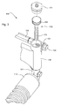
- is a partially exploded perspective view of an adjustment screw mechanism of the height of cut adjustment system according to a first embodiment.
-
Figs. 1-3 show a height of cutadjustment system 101 for a reel type grass cutting unit according to a first embodiment of the invention. The reel type grass cutting unit has ahorizontal shaft 102 that rotates to turncutting reel 103, to cut grass between the cutting reel and bed knife 104. Motor 105 may be used to rotateshaft 102, and may be electric or hydraulic. - In one embodiment, height of
cut adjustment system 101 includes four independent adjustment mechanisms, each of which may be rigidly attached to and support a corner ofcutting unit frame 106. The independent adjustment mechanisms may be adjustment screw mechanisms 108-11.Front ground roller 112 may be attached to the lower portion of a pair of front adjustment screw mechanisms 108-09, andrear ground roller 113 may be attached to the lower portion of a pair of rear adjustment screw mechanisms 110-11. The opposing ends of the front and rear ground rollers may be rotatably mounted to the lower portions of the adjustment screw mechanisms so that the ground rollers may rotate as they roll across the turf and support the cutting unit at a desired cutting height. - In one embodiment, each adjustment screw mechanism 108-11 can change the position of a vertical post 121-24 mounted to the end of a ground roller. Each post 121-24 can move vertically up or down within a sleeve 116-19 rigidly mounted to a corner of the cutting unit frame.
- In one embodiment, each post 121-24 can move vertically up or down within a sleeve 116-19 by turning an adjustment screw 126-29. Each adjustment screw 126-29 includes externally threaded screw shaft 175-78 and worm gear 164-67. Externally threaded screw shaft 175-78 engages internal threads in an axial bore through post 121-24. Worm gears 164-67, at the top end of adjustment screws 126-29, are concentric to the screw shafts. Each sleeve may be covered by a cap 171-74.
- In one embodiment, each adjustment screw 126-29 may be turned by rotating worm shaft 144-47 that engages worm gear 164-67. Each worm shaft 144-47 is perpendicular to worm gear 164-67. Each worm shaft 144-47 may extend through a case 151-54 open to the side of a sleeve 116-19, so that it can engage each worm gear 164-67. Additionally, each worm shaft 144-47 may have a hex head extending out from the end of the case so that it can be gripped and turned with a wrench or power drill socket, or the worm shaft may be turned by other devices such as those described in more detail below. When viewed from above, each worm shaft 144-47 may be approximately 25 mm to the side of the worm gear axis.
- In one embodiment,
worm shafts worm shafts drive shafts worm shafts drive shafts Shaft connectors 140 may slide over the ends of the drive shafts and worm shafts to connect them together. The shaft connectors may be removed to disconnect the shafts as necessary, so that an operator can manually preset parallelism and/or attitude of the cutting units. - In one embodiment, the adjustment screw mechanisms on the left side and right side of the cutting unit may be linked together so that all four mechanisms can be driven synchronously, to change the cut height, from a single adjustment point. For example, the mechanical linkage may be drive
shaft 135 that connects between the left and right adjustment screw mechanisms. Worm shafts 148-49 may be attached to the opposing ends ofdrive shaft 135 using shaft connectors. Each worm shaft 148-49 may extend through a case 158-59. Each case 158-59 may be open to the side of sleeve 156-57 so that worm shaft 148-49 can engage screw gear 137-38. Screw gears 137-38 extend through sleeves 156-57 mounted toframe 106. Screwgear 137 may be connected betweendrive shafts spacer 161. A screw gear (not shown) also may be connected betweendrive shafts spacer 162. - Instead of drive shafts linking the adjustment screw mechanisms, the mechanical linkage may be a synchronous belt or chain drive that links the mechanisms together. Driving all four adjustment screw mechanisms synchronously allows an operator to adjust the entire cut height at one adjustment point. Alternatively, each pair of adjustment screw mechanisms (e.g., the front pair of mechanisms, and the rear pair of mechanisms) may be linked together so that each pair may be driven synchronously from one adjustment point, and the cut height may be changed from only two adjustment points.
- In one embodiment, the adjustment point may be a hex head on the end of each worm shaft that may be driven by a hand wrench in a manual adjustment system. Alternatively, the adjustment point may be a hex head on the end of the worm shaft that may be driven using a portable power source such as an electric drill unattached from the cutting unit. Alternatively, as described above, the adjustment point may be driven by a power source attached to the frame of the reel cutting unit, such as dedicated
electric motor 142 shown inFigs. 1-3 . The dedicated electric motor may be a DC motor mounted to cuttingunit frame 106 so that it may turndrive shaft 135 and drive all four adjustment screw mechanisms synchronously. Additionally, the electric motor may be connected to a control computer and user interface as part of a self adjusting reel system. - In one embodiment, a mechanical counter may be mounted to one of the drive shafts. The mechanical counter may increment with each rotation of the drive shaft, and indicate actual cut height. For example, if adjustment screws 126-29 have a pitch of 20 threads per inch, each rotation of the adjustment screw will change the cut height 0.05 inch. If the worm gear drive ratio is 50:1, each rotation of a drive shaft 131-35 will turn the adjustment screw 1/50th of a turn. As a result, each turn of the drive shaft will change the cut height 0.001 inch. The mechanical counter may indicate the cut height to .001 inch resolution.
- In one embodiment, the drive ratio of the linkage that connects the drive shafts may be arranged such that the attitude of the cutting mechanism increases with increasing cutting height. For example, if the front and rear drive shafts are driven at the same rate, the front of the cutting unit may raise as the adjusting screws turn at the same rate.
- The height of cut adjustment system of the present invention provides adjustment flexibility because the ground rollers can be adjusted to be parallel with each other and the bedknife. A pair of adjustment screws, or all four adjustment screws, may be linked together synchronously so that the cut height may be set or changed at one adjustment point. This reduces the work required to set or adjust the height of cut. Optionally, each adjustment point may have a mechanical and/or digital display indicating the cut height. The adjustment point may be powered by a portable electric tool, so that the adjustment may be performed quickly. Alternatively, the adjustment point may be powered by a dedicated actuator as part of a self adjusting reel system.
- Having described a preferred embodiment, it will become apparent that various modifications can be made without departing from the scope of the invention as defined in the accompanying claims.
Claims (10)
- A height of cut adjustment system (101) for a reel type grass cutting unit, comprising a plurality of adjustment mechanisms between the cutting unit and a vertical post (121 - 124) supporting the cutting unit at a cutting height; characterized by a mechanical linkage between the adjustment mechanisms to permit driving all of the plurality of adjustment mechanisms synchronously from a single adjustment point to change the cutting height.
- The height of cut adjustment system according to claim 1, characterized in that the mechanical linkage is a drive shaft (131, 132, 133, 134) preferably further comprising a worm gear drive between the drive shaft (132, 132, 133, 134) and each adjustment mechanism, a synchronous belt or a chain drive.
- The height of cut adjustment system according to claim 1 or 2, characterized in that the single adjustment point may be driven by a hand wrench, wherein the single adjustment point preferably is a is a hex head.
- The height of cut adjustment system according to one or several of the previous claims, characterized in that each adjustment mechanism is an adjustment screw mechanism (108 - 111).
- The height of cut adjustment system according to one or several of the previous claims, characterized by a dedicated electric motor (142) mounted to the cutting unit to drive the plurality of adjustment mechanisms from the single adjustment point.
- The height of cut adjustment system according to one or several of the previous claims, characterized in that an adjustment mechanism is mounted at each corner of the cutting unit;
- The height of cut adjustment system according to one or several of the claims 2 to 6, characterized in that the drive shaft is between a pair of adjustment mechanisms, wherein the at least one drive shaft (131, 132, 133, 134) is preferably horizontally aligned.
- The height of cut adjustment system according to one or several of the previous claims, characterized in the adjustment mechanism operates to raise and lower the vertical post (121 - 124).
- The height of cut adjustment system according to one or several of the previous claims, characterized in that a ground roller (113) is rotatably mounted to the vertical post (121 - 124).
- The height of cut adjustment system according to one or several of the claims 2 to 9, characterized by at least two of the worm gear drives being concentric.
Applications Claiming Priority (1)
| Application Number | Priority Date | Filing Date | Title |
|---|---|---|---|
| US11/675,666 US7395648B1 (en) | 2007-02-16 | 2007-02-16 | Height of cut adjustment system for reel mower |
Publications (2)
| Publication Number | Publication Date |
|---|---|
| EP1958491A1 true EP1958491A1 (en) | 2008-08-20 |
| EP1958491B1 EP1958491B1 (en) | 2013-03-06 |
Family
ID=39358353
Family Applications (1)
| Application Number | Title | Priority Date | Filing Date |
|---|---|---|---|
| EP08101154A Ceased EP1958491B1 (en) | 2007-02-16 | 2008-01-31 | Height of cut adjustment system for reel mower |
Country Status (2)
| Country | Link |
|---|---|
| US (1) | US7395648B1 (en) |
| EP (1) | EP1958491B1 (en) |
Cited By (1)
| Publication number | Priority date | Publication date | Assignee | Title |
|---|---|---|---|---|
| EP3162177A1 (en) * | 2015-10-28 | 2017-05-03 | Amazonen-Werke H. Dreyer GmbH & Co. KG | Device for the maintenance of green areas |
Families Citing this family (30)
| Publication number | Priority date | Publication date | Assignee | Title |
|---|---|---|---|---|
| US20070234698A1 (en) * | 2006-04-11 | 2007-10-11 | Deere & Company, A Delaware Corporation | DC electric motor to adjust reel functions |
| GB0624547D0 (en) * | 2006-12-08 | 2007-01-17 | Advanced Engineering Tech Ltd | Improvements to height adjustment mechanisms for a grass treatment device |
| US7624560B1 (en) * | 2008-10-07 | 2009-12-01 | Humphrey John L | Depth/height adjuster for a grass treatment insert |
| US8356465B2 (en) * | 2010-02-10 | 2013-01-22 | Deere & Company | Height of cut adjuster assembly for reel mower cutting unit with removable attachment |
| CN102273354A (en) * | 2010-06-09 | 2011-12-14 | 泉峰(中国)贸易有限公司 | Lawn maintenance equipment |
| US8371095B2 (en) | 2011-03-04 | 2013-02-12 | Briggs & Stratton Corporation | Height of cut adjustment system for a walk behind mower |
| USD651218S1 (en) | 2011-06-13 | 2011-12-27 | Fiskars Brands, Inc. | Reel mower |
| USD651217S1 (en) | 2011-06-13 | 2011-12-27 | Fiskars Brands, Inc. | Reel mower |
| EP2869690B1 (en) | 2012-07-04 | 2017-11-01 | Husqvarna Ab | Adjustment of cutting height for a robotic mower |
| US9301444B2 (en) | 2014-05-02 | 2016-04-05 | Deere & Company | Rotary cutting deck height of cut adjustment mechanism |
| US9598829B2 (en) * | 2014-08-06 | 2017-03-21 | Deere & Company | Snowblower skid shoe height adjustment mechanism |
| US11172607B2 (en) | 2016-06-30 | 2021-11-16 | Tti (Macao Commercial Offshore) Limited | Autonomous lawn mower and a system for navigating thereof |
| CN109416543B (en) | 2016-06-30 | 2022-11-08 | 创科(澳门离岸商业服务)有限公司 | Autonomous mower and navigation system thereof |
| US10939615B2 (en) * | 2017-10-26 | 2021-03-09 | Firefly Automatix, Inc. | Adjustable mower deck |
| US11160207B2 (en) * | 2017-10-26 | 2021-11-02 | Firefly Automatix, Inc. | Height adjustable mower deck |
| US11206759B2 (en) | 2017-11-21 | 2021-12-28 | The Toro Company | Mower quick height of cut adjustment |
| US10694665B2 (en) | 2017-12-14 | 2020-06-30 | Clark Equipment Company | Cutter-deck leveling fine adjustment |
| CN108029326A (en) * | 2018-02-01 | 2018-05-15 | 济源新航园艺有限公司 | A kind of garden lawn trimmer based on thread slider principle |
| US11570948B2 (en) | 2018-08-31 | 2023-02-07 | Briggs & Stratton, Llc | Single height adjustment and control assembly for walk-behind outdoor power equipment |
| US10834869B2 (en) | 2019-02-20 | 2020-11-17 | Honda Motor Co., Ltd. | Lift assembly for a lawnmower and lawnmower having same |
| US12296694B2 (en) | 2021-03-10 | 2025-05-13 | Techtronic Cordless Gp | Lawnmowers |
| US11871695B2 (en) | 2021-03-25 | 2024-01-16 | Deere & Company | Height of cut adjustment system |
| CN113859863A (en) * | 2021-10-09 | 2021-12-31 | 湖北新日电动车有限公司 | Two-wheeled electric motor car motorcycle frame assembly line |
| US12443180B2 (en) | 2021-11-10 | 2025-10-14 | Techtronic Cordless Gp | Robotic lawn mowers |
| AU2023200381A1 (en) | 2022-01-31 | 2023-08-17 | Techtronic Cordless Gp | Robotic garden tool |
| EP4270138A1 (en) | 2022-04-28 | 2023-11-01 | Techtronic Cordless GP | Creation of a virtual boundary for a robotic garden tool |
| US12472611B2 (en) | 2022-05-31 | 2025-11-18 | Techtronic Cordless Gp | Peg driver |
| AU2023204696A1 (en) | 2022-07-19 | 2024-02-08 | Techtronic Cordless Gp | Display for controlling robotic tool |
| EP4340296B1 (en) | 2022-07-29 | 2025-04-09 | Techtronic Cordless GP | Generation of a cryptography key for a robotic garden tool |
| CN118120441A (en) * | 2024-04-19 | 2024-06-04 | 绿友机械集团股份有限公司 | Garden lawn maintenance knife holder |
Citations (4)
| Publication number | Priority date | Publication date | Assignee | Title |
|---|---|---|---|---|
| US2340849A (en) * | 1941-10-22 | 1944-02-08 | Frank W Wildeboor | Lawn mower |
| US3217479A (en) * | 1963-04-29 | 1965-11-16 | Scott & Sons Co O M | Combined height adjustment for reel mower |
| EP1474962A1 (en) * | 2003-04-30 | 2004-11-10 | Deere & Company | Height-of-cut adjustment system for reel mower |
| WO2007118925A1 (en) | 2006-04-13 | 2007-10-25 | Actioneco Oy | Grass cutting unit |
Family Cites Families (22)
| Publication number | Priority date | Publication date | Assignee | Title |
|---|---|---|---|---|
| US2924055A (en) * | 1960-02-09 | Power mower having drive controlled by mower handle | ||
| US3106813A (en) * | 1961-04-17 | 1963-10-15 | Jacobsen Mfg Co | Reel type lawn mower cutting adjustment |
| GB1437261A (en) * | 1973-03-28 | 1976-05-26 | Ransomes Sims & Jefferies Ltd | Lawn mowers |
| US4021996A (en) * | 1976-02-26 | 1977-05-10 | Bartlett Gordon E | Golf greens mower |
| US4335569A (en) | 1980-10-22 | 1982-06-22 | The Toro Company | Reel to bedknife adjustment system |
| US4479346A (en) | 1981-03-31 | 1984-10-30 | Noel Chandler | Automatic electrical bed knife adjuster |
| US4644737A (en) * | 1983-09-20 | 1987-02-24 | Brouwer Turf Equipment Limited | Mower |
| US4606178A (en) | 1984-12-24 | 1986-08-19 | Textron Inc. | Lawnmower reel-to-bedknife adjustment system |
| US4663924A (en) | 1985-09-27 | 1987-05-12 | Textron Inc. | Apparatus and method for establishing reel-to-bedknife clearance |
| US4878340A (en) * | 1988-01-29 | 1989-11-07 | The Toro Company | Turf grooming reel |
| US5228277A (en) * | 1992-01-23 | 1993-07-20 | Deere & Company | Rear discharge reel mower having multi-purpose rotary brush |
| US5600942A (en) | 1995-03-31 | 1997-02-11 | New Holland North America, Inc. | Adaptive thresholding for metal detection |
| US5732538A (en) * | 1995-07-05 | 1998-03-31 | Deere & Company | Springless roller scraper mechanism |
| US5865016A (en) * | 1997-02-07 | 1999-02-02 | Ransomes America Corporation | Release mechanism for cutting head of a gang mower |
| US5950409A (en) * | 1997-05-16 | 1999-09-14 | Davies; Douglas N. | Flex head turf cutting unit |
| US5970690A (en) * | 1997-10-24 | 1999-10-26 | Ransomes America Corporation | Leveling apparatus for a cutting head of a mower |
| US6237313B1 (en) * | 1999-08-13 | 2001-05-29 | Deere & Company | Grass catcher support assembly for reel mower cutting unit |
| US6651415B2 (en) * | 2002-01-28 | 2003-11-25 | National Mower Cormpany | Height adjustment apparatus for turf maintenance equipment |
| US6688094B2 (en) * | 2002-02-01 | 2004-02-10 | The Toro Company | Belt driven roller brush assembly |
| US6732500B1 (en) * | 2003-04-04 | 2004-05-11 | Robert J. Myers | Mower height adjustment system |
| US7231757B2 (en) | 2003-04-30 | 2007-06-19 | Deere & Company | Method and apparatus for setting and maintaining reel-to-bedknife clearance |
| US7121073B2 (en) | 2003-04-30 | 2006-10-17 | Deere & Company | Cutting reel adjusting system |
-
2007
- 2007-02-16 US US11/675,666 patent/US7395648B1/en active Active
-
2008
- 2008-01-31 EP EP08101154A patent/EP1958491B1/en not_active Ceased
Patent Citations (5)
| Publication number | Priority date | Publication date | Assignee | Title |
|---|---|---|---|---|
| US2340849A (en) * | 1941-10-22 | 1944-02-08 | Frank W Wildeboor | Lawn mower |
| US3217479A (en) * | 1963-04-29 | 1965-11-16 | Scott & Sons Co O M | Combined height adjustment for reel mower |
| EP1474962A1 (en) * | 2003-04-30 | 2004-11-10 | Deere & Company | Height-of-cut adjustment system for reel mower |
| WO2007118925A1 (en) | 2006-04-13 | 2007-10-25 | Actioneco Oy | Grass cutting unit |
| EP2009980A1 (en) | 2006-04-13 | 2009-01-07 | Actioneco OY | Grass cutting unit |
Cited By (1)
| Publication number | Priority date | Publication date | Assignee | Title |
|---|---|---|---|---|
| EP3162177A1 (en) * | 2015-10-28 | 2017-05-03 | Amazonen-Werke H. Dreyer GmbH & Co. KG | Device for the maintenance of green areas |
Also Published As
| Publication number | Publication date |
|---|---|
| EP1958491B1 (en) | 2013-03-06 |
| US7395648B1 (en) | 2008-07-08 |
Similar Documents
| Publication | Publication Date | Title |
|---|---|---|
| EP1958491B1 (en) | Height of cut adjustment system for reel mower | |
| US20080196377A1 (en) | Height of cut adjustment system for reel mower | |
| AU2004200522B8 (en) | Height-of-cut adjustment system for reel mower | |
| US7908834B2 (en) | Grass cutting unit | |
| DE69103397T3 (en) | Beds. | |
| EP1844641B1 (en) | Reel mower cutting unit | |
| DE602004003419T2 (en) | Schneidtrommelverstellsystem | |
| EP1844640B1 (en) | An apparatus to adjust the reel-to-bedknife gap of a reel mower cutting unit and a method for adjusting the reel-to-bedknife gap or height-of cut on a cutting reel unit | |
| EP0808558B1 (en) | Reel mower with scraping means for the ground-engaging roller | |
| DE102006043972A1 (en) | Drive mechanism and cutting device for food slicer | |
| DE102012016348B4 (en) | Soil preparation device with a device for damming, collecting or processing soil or mulch | |
| US20190150360A1 (en) | Adjustable mower deck | |
| EP0264011B1 (en) | Topping assembly for beet-harvesting machines | |
| DE102007022037B3 (en) | Treatment chair with headrest control and method for adjusting a treatment chair | |
| CN219228417U (en) | Self-moving mowing equipment | |
| EP2353361A1 (en) | Height of cut adjuster assembly for a reel mower cutting unit | |
| EP0685148A1 (en) | Mowing and/or aerating machine | |
| DE10325187B4 (en) | Cylinder mowers | |
| CN109451956B (en) | Synchronous adjusting device for mowing height of mower | |
| EP2984919A1 (en) | Method for harvesting vegetables and salads | |
| DE2943732A1 (en) | Tool for seed bed preparation - includes breaker roller fitted under safety hood hinged to frame | |
| CN221748852U (en) | A potato film covering and sowing integrated device | |
| CN223979188U (en) | A drone-based tea tree lateral branch pruning device | |
| CN219812439U (en) | Adjustable novel harrowing and soil preparation machine | |
| DE3150488C2 (en) | Mulcher |
Legal Events
| Date | Code | Title | Description |
|---|---|---|---|
| PUAI | Public reference made under article 153(3) epc to a published international application that has entered the european phase |
Free format text: ORIGINAL CODE: 0009012 |
|
| AK | Designated contracting states |
Kind code of ref document: A1 Designated state(s): AT BE BG CH CY CZ DE DK EE ES FI FR GB GR HR HU IE IS IT LI LT LU LV MC MT NL NO PL PT RO SE SI SK TR |
|
| AX | Request for extension of the european patent |
Extension state: AL BA MK RS |
|
| 17P | Request for examination filed |
Effective date: 20090220 |
|
| 17Q | First examination report despatched |
Effective date: 20090330 |
|
| AKX | Designation fees paid |
Designated state(s): DE GB |
|
| GRAP | Despatch of communication of intention to grant a patent |
Free format text: ORIGINAL CODE: EPIDOSNIGR1 |
|
| GRAS | Grant fee paid |
Free format text: ORIGINAL CODE: EPIDOSNIGR3 |
|
| GRAA | (expected) grant |
Free format text: ORIGINAL CODE: 0009210 |
|
| AK | Designated contracting states |
Kind code of ref document: B1 Designated state(s): DE GB |
|
| REG | Reference to a national code |
Ref country code: GB Ref legal event code: FG4D |
|
| REG | Reference to a national code |
Ref country code: DE Ref legal event code: R096 Ref document number: 602008022650 Country of ref document: DE Effective date: 20130502 |
|
| PLBE | No opposition filed within time limit |
Free format text: ORIGINAL CODE: 0009261 |
|
| STAA | Information on the status of an ep patent application or granted ep patent |
Free format text: STATUS: NO OPPOSITION FILED WITHIN TIME LIMIT |
|
| 26N | No opposition filed |
Effective date: 20131209 |
|
| REG | Reference to a national code |
Ref country code: DE Ref legal event code: R097 Ref document number: 602008022650 Country of ref document: DE Effective date: 20131209 |
|
| PGFP | Annual fee paid to national office [announced via postgrant information from national office to epo] |
Ref country code: DE Payment date: 20191219 Year of fee payment: 13 |
|
| REG | Reference to a national code |
Ref country code: DE Ref legal event code: R119 Ref document number: 602008022650 Country of ref document: DE |
|
| PG25 | Lapsed in a contracting state [announced via postgrant information from national office to epo] |
Ref country code: DE Free format text: LAPSE BECAUSE OF NON-PAYMENT OF DUE FEES Effective date: 20210803 |
|
| PGFP | Annual fee paid to national office [announced via postgrant information from national office to epo] |
Ref country code: GB Payment date: 20240129 Year of fee payment: 17 |
|
| GBPC | Gb: european patent ceased through non-payment of renewal fee |
Effective date: 20250131 |
|
| PG25 | Lapsed in a contracting state [announced via postgrant information from national office to epo] |
Ref country code: GB Free format text: LAPSE BECAUSE OF NON-PAYMENT OF DUE FEES Effective date: 20250131 |