EP1957162B1 - A strain reliever for a lead of an implantable heart stimulator - Google Patents
A strain reliever for a lead of an implantable heart stimulator Download PDFInfo
- Publication number
- EP1957162B1 EP1957162B1 EP05812117.9A EP05812117A EP1957162B1 EP 1957162 B1 EP1957162 B1 EP 1957162B1 EP 05812117 A EP05812117 A EP 05812117A EP 1957162 B1 EP1957162 B1 EP 1957162B1
- Authority
- EP
- European Patent Office
- Prior art keywords
- strain reliever
- groove
- cable
- strain
- lead
- Prior art date
- Legal status (The legal status is an assumption and is not a legal conclusion. Google has not performed a legal analysis and makes no representation as to the accuracy of the status listed.)
- Expired - Lifetime
Links
Images

Classifications
-
- A—HUMAN NECESSITIES
- A61—MEDICAL OR VETERINARY SCIENCE; HYGIENE
- A61N—ELECTROTHERAPY; MAGNETOTHERAPY; RADIATION THERAPY; ULTRASOUND THERAPY
- A61N1/00—Electrotherapy; Circuits therefor
- A61N1/02—Details
- A61N1/04—Electrodes
- A61N1/05—Electrodes for implantation or insertion into the body, e.g. heart electrode
- A61N1/056—Transvascular endocardial electrode systems
-
- A—HUMAN NECESSITIES
- A61—MEDICAL OR VETERINARY SCIENCE; HYGIENE
- A61N—ELECTROTHERAPY; MAGNETOTHERAPY; RADIATION THERAPY; ULTRASOUND THERAPY
- A61N1/00—Electrotherapy; Circuits therefor
- A61N1/18—Applying electric currents by contact electrodes
- A61N1/32—Applying electric currents by contact electrodes alternating or intermittent currents
- A61N1/36—Applying electric currents by contact electrodes alternating or intermittent currents for stimulation
- A61N1/372—Arrangements in connection with the implantation of stimulators
- A61N1/375—Constructional arrangements, e.g. casings
- A61N1/3752—Details of casing-lead connections
Definitions
- a helical groove is therefore formed in the peripheral surface of the body along at least a part of the body length, said groove ending at the departure point at the distal end of the body and the groove is designed for receiving at least a part of the proximal end portion of the cable.
Landscapes
- Health & Medical Sciences (AREA)
- Heart & Thoracic Surgery (AREA)
- Vascular Medicine (AREA)
- Cardiology (AREA)
- Engineering & Computer Science (AREA)
- Biomedical Technology (AREA)
- Nuclear Medicine, Radiotherapy & Molecular Imaging (AREA)
- Radiology & Medical Imaging (AREA)
- Life Sciences & Earth Sciences (AREA)
- Animal Behavior & Ethology (AREA)
- General Health & Medical Sciences (AREA)
- Public Health (AREA)
- Veterinary Medicine (AREA)
- Electrotherapy Devices (AREA)
Description
- The present invention relates to a strain reliever for a lead of an implantable heart stimulator, said lead including at least one electric cable having an electric conductor, and said strain reliever comprising a body of electrically conducting material in electric contact with the electric conductor, which body is lockable in a position in electric contact with electric circuitry of the heart stimulator.
- When applying a pulling force to a conventional heart stimulator lead having coil conductors part of the pulling force is absorbed by the coils, however, the weld joint of the conductors to connector pins have appeared to be weak points with an apparent risk of breakage. To try to reduce this risk of breakage different strain relief means have been suggested. In e.g.
US 5 433 734 a strain relief collar of for instance silicon rubber is described. The collar is surrounding the connector pin and the terminal end of the lead. Another example is disclosed inUS 2004/0106964 wherein a strain relief tube which is mounted on a connector unit of a heart stimulator couples the lead body to this connector unit. - In new lead technology the coil conductor is often replaced by a cable having a straight electric conductor. Such a lead structure will make the lead body stiff in longitudinal direction and a pulling force in the lead will be applied practically in its entirety to the weld joint of the lead to the connector pin or ring.
- The risk of breakage at the point where the cable is welded, at the connector end of the lead, is thus increased in this new lead structure. For an example of such a new lead structure the force needed to break the cable itself is more than 30 N, whereas a force of about 17 N has appeared to be sufficient for breaking the weld.
- The purpose of the present invention is therefore to propose a solution to this problem which provides a sufficient strain relief at the proximal end of such a lead structure to avoid breakage at the weld joint.
- This purpose of the invention is obtained by a strain reliever of the kind defined in claim 1. Thus, by the invention a simple construction is provided for absorbing most of the pulling force in the lead such that the weld is efficiently relieved.
- To obtain an efficient absorption of the pulling force by helically winding the lead cable on the peripheral surface of the strain reliever body the cable must be fixed to leave the distal end of the strain reliever body at a specific departure point. According to an advantageous embodiment of the strain reliever according to the invention a helical groove is therefore formed in the peripheral surface of the body along at least a part of the body length, said groove ending at the departure point at the distal end of the body and the groove is designed for receiving at least a part of the proximal end portion of the cable. By placing the cable in such a groove at the distal end of the strain reliever body the cable will leave the distal end at the outlet of the groove.
- According to still another advantageous embodiment of the strain reliever according to the invention the groove is extending from the departure point to at least the fastening point and the fastening point is located in the groove. By applying the cable in a groove on the peripheral surface of the body the cable is held in place on the body in a secure way.
- According to yet another advantageous embodiment of the strain reliever according to the invention the groove is inclined towards to the distal end of the body by a predetermined angle. This inclination angle can amount to 30 degrees. By having an inclined groove the risk for the cable to creep out of the groove is further reduced. When a pulling force is applied in the longitudinal direction of the cable the cable will be further pulled against the bottom of the groove.
- According to another advantageous embodiment of the strain reliever according to the invention the body is made of a stainless alloy, preferably a Co-Ni-Mo-Cr-alloy denoted by a MP35N LT. This is a biocompatible material which is easy to weld and frequently used in this field.
- The invention also relates to a lead for an implantable heart stimulator including at least one electric cable having an electric conductor, which lead is provided with the above strain reliever.
- To further explain the invention an embodiment of the strain reliever according to the invention will now be described in greater detail with reference to the drawings on which
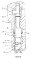
figure 1 and 2 shows a side view of the strain reliever body with a cable applied in a helical groove in the peripheral surface,figure 2 is a cross section of the groove in the strain reliever body shown infigure 1 , andfigure 3 is a cross section of the header of a heart stimulator with a connected lead provided with a strain reliever according to the invention. -
Figure 1 shows an embodiment of the strain reliever according to the invention in a side view. The strain reliever comprises acylindrical body 2 with ahelical groove 4 formed in the peripheral surface. In the shown embodiment thecylindrical body 2 comprises twosections body 2 is made of an electrically conducting material, like the stainless alloy Co-Ni-Mo-Cr-alloy denoted by MP35N LT. This alloy is biocompatible, well tested in this field and easy to weld. - In the groove 4 a
cable 10 of the lead is applied. Thecable 10 is fastened to thebody 2 at a fastening point at the proximal end of thegroove 4 by aweld 12. Thecable 10 is extending in the distal direction of the lead from a departure point at the outlet of the groove at the distal end of thebody 2. - A
connector tube 14 of e.g. silicon is also shown infigure 1 . This silicon tube forms electric isolation for a possible inner connector coil of the lead. -
Figure 2 shows a cross section of thegroove 4. As appears fromfigure 2 the groove is inclined towards the distal end of thebody 2 by an inclination angle of 30 degrees. The magnitude of this inclination angle is not critical and can be varied. Also a groove without inclination will held the cable in place. - By locating the cable in a groove in the peripheral surface of the body the cable is held in place on the strain reliever body in a reliable way, and by inclining the groove as illustrated in
figure 2 the cable is pulled against the bottom of the groove when a pulling force is exerted in the cable in its distal direction, thus further securing the cable in correct position on the body. - As appears from
figure 1 thegroove 4 is extending a bit more than one turn around the periphery of thebody 2. - Experiments have shown that when using a strain reliever of the kind described above in connection with
figures 1 - 2 the pulling force in the lead must be increased from 17 N, as mentioned above, to about 24 N for breaking the weld, i.e. a considerable increase of the breaking strain. -
Figure 3 shows a cross section of the header of a heart stimulator with the proximal end of the lead connected to the header. Although the header is sectioned, the parts of the proximal end of the lead shown inFigure 1 are not sectioned. Thestrain reliever body 2 with thecable 10 in thehelical groove 4 is shown in the left part of the figure.Section 8 of thestrain reliever body 2 is in electrical contact with aconnector ring 16, which in its turn is in electric contact with an electrically conductingring 26 by way of aringshaped tube 28. Aport 30 is provided for connecting thering 26 to electric circuitry of the heart stimulator. - The
strain reliever body 2 is preferably welded to theconnector ring 16 to lock thestrain reliever body 2 to the heart stimulator header. - A
port 32 in the header is shown for screwing a set screw to lock the connector,pin 20 to the header and thus complete the connection of the lead in the header. - The
connector ring 16 and theconnector pin 20 are preferably made of the same electrically conducting, stainless alloy MP35N LT as thestrain reliever body 2. - Above an embodiment is described wherein the cable is located in a helical groove in the peripheral surface of the strain reliever body. The strain reliever according to the invention can, however, also be realized by a strain reliever body without such a groove, on which the proximal end portion of the cable is wound around its periphery. The cable is then welded to the body at a fastening point on the peripheral surface a distance from the distal end of the body. At the distal end of the body a means is provided for fixing the cable to extend in the distal direction from a specific departure point at the body distal end. Such a means for fixing the cable to leave the strain reliever body at the departure point can comprise a groove in the peripheral surface of the body extending only along a part of the distance to the fastening point which groove ends at the departure point. By applying the cable in this groove the cable is locked to leave the strain reliever body at the outlet of this groove. Also other means are possible for fixing the cable to extend in the distal direction from the departure point, like a ring attached to the distal end of the strain reliever body at the departure point. Such an embodiment will have an efficient strain reliving effect as well. A pulling force applied to the cable in this embodiment will be transmitted to the strain reliever body by friction between the cable and the peripheral surface of the strain reliever body.
- Above embodiments of the strain reliever according to the invention is described which are constructed for just one cable. However, it is evident for the man skilled in the art that the strain reliever according to the invention can easily be modified for relieving strains in more than one cable extending in parallel helically around the peripheral surface of the strain reliever body.
Claims (12)
- A strain reliever for a lead of an implantable heart stimulator, said lead including at least one electric cable (10) having a straight electric conductor, and said strain reliever comprising a body (2) of electrically conducting material in electric contact with said electric conductor, which body is lockable in a position in electric contact with electric circuitry of the heart stimulator, wherein said body comprises a fastening means (12) for fastening the proximal end of said cable (10) at a fastening point on the peripheral surface of said body located at a distance from the distal end of said body (2), and in that a means is provided at the distal end of said body for fixing the cable to extend in the distal direction from a departure point at the body distal end, said cable extending in a helical path on the peripheral surface of said body between said fastening point and said departure point.
- The strain reliever according to claim 1, characterized in that said body (2) is substantially cylindrical.
- The strain reliever according to claim 1 or 2, characterized in that a helical groove (4) is formed in the peripheral surface of said body (2) along at least a part of the body length, said groove ending at said departure point at the distal end of said body, and in that said groove is designed for receiving at least a part of the proximal end portion of said cable (10).
- The strain reliever according to claim 3, characterized in that said groove (10) is extending from said departure point along a part of the distance to said fastening point (12).
- The strain reliever according to claim 3, characterized in that said groove (10) is extending from said departure point to at least said fastening point (12), and in that said fastening point is located in said groove.
- The strain reliever according to any one of the claims 3 - 5, characterized in that said groove (4) is inclined towards the distal end of said body (2) by a predetermined angle.
- The strain reliever according to claim 6, characterized in that the inclination angle amounts to 30 degrees.
- The strain reliever according to any one of the claims 3 - 7, characterized in that said groove (4) is extending along at least one turn around the periphery of said body (2).
- The strain reliever according to any one of the preceding claims, characterized in that said fastening means comprise a weld (12).
- The strain reliever according to any one of the preceding claims, characterized in that said body (2) is made of an electrically conducting, stainless alloy, preferably a Co-Ni-Mo-Cr-alloy denoted by MP35N LT.
- The strain reliever according to any one of the preceding claims, characterized in that said body is designed for receiving more than one cable extending helically, substantially in parallel on the body peripheral surface between said fastening and said departure points.
- A lead for an implantable heart stimulator including at least one electric cable (10) having an electric conductor, characterized by a strain reliever according to any one of the preceding claims.
Applications Claiming Priority (1)
| Application Number | Priority Date | Filing Date | Title |
|---|---|---|---|
| PCT/SE2005/001809 WO2007064262A1 (en) | 2005-11-30 | 2005-11-30 | A strain reliever for a lead of an implantable heart stimulator |
Publications (2)
| Publication Number | Publication Date |
|---|---|
| EP1957162A1 EP1957162A1 (en) | 2008-08-20 |
| EP1957162B1 true EP1957162B1 (en) | 2013-10-02 |
Family
ID=38092497
Family Applications (1)
| Application Number | Title | Priority Date | Filing Date |
|---|---|---|---|
| EP05812117.9A Expired - Lifetime EP1957162B1 (en) | 2005-11-30 | 2005-11-30 | A strain reliever for a lead of an implantable heart stimulator |
Country Status (3)
| Country | Link |
|---|---|
| US (1) | US7945328B2 (en) |
| EP (1) | EP1957162B1 (en) |
| WO (1) | WO2007064262A1 (en) |
Cited By (1)
| Publication number | Priority date | Publication date | Assignee | Title |
|---|---|---|---|---|
| DE102017219417A1 (en) | 2017-10-30 | 2019-05-02 | Leoni Kabel Gmbh | damping element |
Families Citing this family (5)
| Publication number | Priority date | Publication date | Assignee | Title |
|---|---|---|---|---|
| WO2009078752A1 (en) | 2007-12-18 | 2009-06-25 | St. Jude Medical Ab | Medical implantable lead and method for manufacturing of such a lead |
| US8968355B2 (en) * | 2008-08-04 | 2015-03-03 | Covidien Lp | Articulating surgical device |
| DE102012217941B3 (en) | 2012-10-01 | 2014-02-13 | Aktiebolaget Skf | Cable strain relief bracket |
| US11266828B2 (en) * | 2018-12-06 | 2022-03-08 | Medtronic, Inc. | Implantable medical lead with moveable conductors |
| US20240024689A1 (en) * | 2020-11-18 | 2024-01-25 | Nyxoah SA | Stack design implant device |
Family Cites Families (7)
| Publication number | Priority date | Publication date | Assignee | Title |
|---|---|---|---|---|
| US4995389A (en) | 1985-12-16 | 1991-02-26 | Telectronics Pacing Systems, Inc. | Multielectrode quick connect cardiac pacing lead connector assembly |
| US4944088A (en) | 1988-05-25 | 1990-07-31 | Medtronic, Inc. | Ring electrode for multiconductor pacing leads |
| US5324312A (en) * | 1992-05-06 | 1994-06-28 | Medtronic, Inc. | Tool-less threaded connector assembly |
| US5676694A (en) | 1996-06-07 | 1997-10-14 | Medtronic, Inc. | Medical electrical lead |
| US5954759A (en) | 1997-04-21 | 1999-09-21 | Medtronic, Inc. | Fracture resistant medical electrical lead |
| US6755694B2 (en) * | 2001-04-19 | 2004-06-29 | Medtronic, Inc. | Lead upsizing sleeve |
| DE10317867B3 (en) | 2003-04-17 | 2004-10-07 | Amphenol-Tuchel Electronics Gmbh | Contact arrangement for contacting electrical conductor has one-piece contact element with contact part for contacting matching counter contact and connector part for holding end of conductor |
-
2005
- 2005-11-30 EP EP05812117.9A patent/EP1957162B1/en not_active Expired - Lifetime
- 2005-11-30 US US12/093,782 patent/US7945328B2/en not_active Expired - Fee Related
- 2005-11-30 WO PCT/SE2005/001809 patent/WO2007064262A1/en not_active Ceased
Cited By (1)
| Publication number | Priority date | Publication date | Assignee | Title |
|---|---|---|---|---|
| DE102017219417A1 (en) | 2017-10-30 | 2019-05-02 | Leoni Kabel Gmbh | damping element |
Also Published As
| Publication number | Publication date |
|---|---|
| US7945328B2 (en) | 2011-05-17 |
| EP1957162A1 (en) | 2008-08-20 |
| WO2007064262A1 (en) | 2007-06-07 |
| US20080288014A1 (en) | 2008-11-20 |
Similar Documents
| Publication | Publication Date | Title |
|---|---|---|
| US6061598A (en) | Fracture resistant medical electrical lead | |
| US4538623A (en) | Thread electrode assembly | |
| US4463765A (en) | Screw-in pacing lead assembly | |
| EP1556130B1 (en) | Methods and apparatus for joining small diameter conductors within medical electrical leads | |
| US5507787A (en) | Adaptor device for electrode catheters | |
| US7162310B2 (en) | Flat wire helix electrode used in screw-in cardiac stimulation leads | |
| US6181971B1 (en) | Joining conductor cables and electrodes on a multi-lumen lead body | |
| US6038463A (en) | Medical electrical lead | |
| US8321033B2 (en) | Implantable medical lead having passive lock mechanical body terminations | |
| US8150536B2 (en) | Low profile active fixation cardiac lead having torque transmitting means | |
| US9037265B2 (en) | Retractable screw intracardiac lead for cardiac stimulation and/or defibrillation | |
| JP2005514181A (en) | Medical leads and lead connector systems | |
| JPH06327776A (en) | Implantable lead | |
| US8594810B2 (en) | Medical implantable lead and method for manufacturing of such a lead | |
| US6016436A (en) | Medical electrical lead | |
| US20030167082A1 (en) | Set for installing an intracardiac stimulation or defibrillation lead equipped with a screw | |
| US6489562B1 (en) | Medical electrical lead having variable stiffness tip-ring spacer | |
| CN103702712A (en) | Implantable passive medical lead | |
| US7945328B2 (en) | Strain reliever for a lead of an implantable heart stimulator | |
| EP0980281B1 (en) | Medical electrical lead | |
| US5697804A (en) | Implantable cardiac stimulator having a locking device for releasably retaining a pin-like element of an electrode lead | |
| EP4559512A1 (en) | Transmission module and electrical stimulation device | |
| JP2005512605A (en) | Lead size expansion sleeve | |
| US20080319520A1 (en) | Endocardial Lead | |
| US8321034B2 (en) | Stimulation electrode lead |
Legal Events
| Date | Code | Title | Description |
|---|---|---|---|
| PUAI | Public reference made under article 153(3) epc to a published international application that has entered the european phase |
Free format text: ORIGINAL CODE: 0009012 |
|
| 17P | Request for examination filed |
Effective date: 20080630 |
|
| AK | Designated contracting states |
Kind code of ref document: A1 Designated state(s): AT BE BG CH CY CZ DE DK EE ES FI FR GB GR HU IE IS IT LI LT LU LV MC NL PL PT RO SE SI SK TR |
|
| DAX | Request for extension of the european patent (deleted) | ||
| GRAP | Despatch of communication of intention to grant a patent |
Free format text: ORIGINAL CODE: EPIDOSNIGR1 |
|
| INTG | Intention to grant announced |
Effective date: 20130506 |
|
| GRAS | Grant fee paid |
Free format text: ORIGINAL CODE: EPIDOSNIGR3 |
|
| GRAA | (expected) grant |
Free format text: ORIGINAL CODE: 0009210 |
|
| AK | Designated contracting states |
Kind code of ref document: B1 Designated state(s): AT BE BG CH CY CZ DE DK EE ES FI FR GB GR HU IE IS IT LI LT LU LV MC NL PL PT RO SE SI SK TR |
|
| REG | Reference to a national code |
Ref country code: GB Ref legal event code: FG4D |
|
| REG | Reference to a national code |
Ref country code: CH Ref legal event code: NV Representative=s name: E. BLUM AND CO. AG PATENT- UND MARKENANWAELTE , CH Ref country code: CH Ref legal event code: EP Ref country code: AT Ref legal event code: REF Ref document number: 634294 Country of ref document: AT Kind code of ref document: T Effective date: 20131015 |
|
| REG | Reference to a national code |
Ref country code: IE Ref legal event code: FG4D |
|
| REG | Reference to a national code |
Ref country code: DE Ref legal event code: R096 Ref document number: 602005041412 Country of ref document: DE Effective date: 20131128 |
|
| REG | Reference to a national code |
Ref country code: AT Ref legal event code: MK05 Ref document number: 634294 Country of ref document: AT Kind code of ref document: T Effective date: 20131002 |
|
| REG | Reference to a national code |
Ref country code: NL Ref legal event code: VDEP Effective date: 20131002 |
|
| PG25 | Lapsed in a contracting state [announced via postgrant information from national office to epo] |
Ref country code: SI Free format text: LAPSE BECAUSE OF FAILURE TO SUBMIT A TRANSLATION OF THE DESCRIPTION OR TO PAY THE FEE WITHIN THE PRESCRIBED TIME-LIMIT Effective date: 20131002 |
|
| REG | Reference to a national code |
Ref country code: LT Ref legal event code: MG4D |
|
| PG25 | Lapsed in a contracting state [announced via postgrant information from national office to epo] |
Ref country code: LT Free format text: LAPSE BECAUSE OF FAILURE TO SUBMIT A TRANSLATION OF THE DESCRIPTION OR TO PAY THE FEE WITHIN THE PRESCRIBED TIME-LIMIT Effective date: 20131002 Ref country code: SE Free format text: LAPSE BECAUSE OF FAILURE TO SUBMIT A TRANSLATION OF THE DESCRIPTION OR TO PAY THE FEE WITHIN THE PRESCRIBED TIME-LIMIT Effective date: 20131002 Ref country code: NL Free format text: LAPSE BECAUSE OF FAILURE TO SUBMIT A TRANSLATION OF THE DESCRIPTION OR TO PAY THE FEE WITHIN THE PRESCRIBED TIME-LIMIT Effective date: 20131002 Ref country code: CZ Free format text: LAPSE BECAUSE OF FAILURE TO SUBMIT A TRANSLATION OF THE DESCRIPTION OR TO PAY THE FEE WITHIN THE PRESCRIBED TIME-LIMIT Effective date: 20131002 Ref country code: FI Free format text: LAPSE BECAUSE OF FAILURE TO SUBMIT A TRANSLATION OF THE DESCRIPTION OR TO PAY THE FEE WITHIN THE PRESCRIBED TIME-LIMIT Effective date: 20131002 Ref country code: BE Free format text: LAPSE BECAUSE OF FAILURE TO SUBMIT A TRANSLATION OF THE DESCRIPTION OR TO PAY THE FEE WITHIN THE PRESCRIBED TIME-LIMIT Effective date: 20131002 Ref country code: IS Free format text: LAPSE BECAUSE OF FAILURE TO SUBMIT A TRANSLATION OF THE DESCRIPTION OR TO PAY THE FEE WITHIN THE PRESCRIBED TIME-LIMIT Effective date: 20140202 |
|
| PG25 | Lapsed in a contracting state [announced via postgrant information from national office to epo] |
Ref country code: AT Free format text: LAPSE BECAUSE OF FAILURE TO SUBMIT A TRANSLATION OF THE DESCRIPTION OR TO PAY THE FEE WITHIN THE PRESCRIBED TIME-LIMIT Effective date: 20131002 Ref country code: PL Free format text: LAPSE BECAUSE OF FAILURE TO SUBMIT A TRANSLATION OF THE DESCRIPTION OR TO PAY THE FEE WITHIN THE PRESCRIBED TIME-LIMIT Effective date: 20131002 Ref country code: ES Free format text: LAPSE BECAUSE OF FAILURE TO SUBMIT A TRANSLATION OF THE DESCRIPTION OR TO PAY THE FEE WITHIN THE PRESCRIBED TIME-LIMIT Effective date: 20131002 Ref country code: LV Free format text: LAPSE BECAUSE OF FAILURE TO SUBMIT A TRANSLATION OF THE DESCRIPTION OR TO PAY THE FEE WITHIN THE PRESCRIBED TIME-LIMIT Effective date: 20131002 Ref country code: CY Free format text: LAPSE BECAUSE OF FAILURE TO SUBMIT A TRANSLATION OF THE DESCRIPTION OR TO PAY THE FEE WITHIN THE PRESCRIBED TIME-LIMIT Effective date: 20131002 |
|
| PG25 | Lapsed in a contracting state [announced via postgrant information from national office to epo] |
Ref country code: PT Free format text: LAPSE BECAUSE OF FAILURE TO SUBMIT A TRANSLATION OF THE DESCRIPTION OR TO PAY THE FEE WITHIN THE PRESCRIBED TIME-LIMIT Effective date: 20140203 |
|
| REG | Reference to a national code |
Ref country code: DE Ref legal event code: R097 Ref document number: 602005041412 Country of ref document: DE |
|
| PG25 | Lapsed in a contracting state [announced via postgrant information from national office to epo] |
Ref country code: MC Free format text: LAPSE BECAUSE OF FAILURE TO SUBMIT A TRANSLATION OF THE DESCRIPTION OR TO PAY THE FEE WITHIN THE PRESCRIBED TIME-LIMIT Effective date: 20131002 Ref country code: EE Free format text: LAPSE BECAUSE OF FAILURE TO SUBMIT A TRANSLATION OF THE DESCRIPTION OR TO PAY THE FEE WITHIN THE PRESCRIBED TIME-LIMIT Effective date: 20131002 |
|
| PLBE | No opposition filed within time limit |
Free format text: ORIGINAL CODE: 0009261 |
|
| STAA | Information on the status of an ep patent application or granted ep patent |
Free format text: STATUS: NO OPPOSITION FILED WITHIN TIME LIMIT |
|
| REG | Reference to a national code |
Ref country code: IE Ref legal event code: MM4A |
|
| PG25 | Lapsed in a contracting state [announced via postgrant information from national office to epo] |
Ref country code: RO Free format text: LAPSE BECAUSE OF FAILURE TO SUBMIT A TRANSLATION OF THE DESCRIPTION OR TO PAY THE FEE WITHIN THE PRESCRIBED TIME-LIMIT Effective date: 20131002 Ref country code: SK Free format text: LAPSE BECAUSE OF FAILURE TO SUBMIT A TRANSLATION OF THE DESCRIPTION OR TO PAY THE FEE WITHIN THE PRESCRIBED TIME-LIMIT Effective date: 20131002 |
|
| 26N | No opposition filed |
Effective date: 20140703 |
|
| GBPC | Gb: european patent ceased through non-payment of renewal fee |
Effective date: 20140102 |
|
| PG25 | Lapsed in a contracting state [announced via postgrant information from national office to epo] |
Ref country code: DK Free format text: LAPSE BECAUSE OF FAILURE TO SUBMIT A TRANSLATION OF THE DESCRIPTION OR TO PAY THE FEE WITHIN THE PRESCRIBED TIME-LIMIT Effective date: 20131002 |
|
| REG | Reference to a national code |
Ref country code: DE Ref legal event code: R097 Ref document number: 602005041412 Country of ref document: DE Effective date: 20140703 |
|
| PG25 | Lapsed in a contracting state [announced via postgrant information from national office to epo] |
Ref country code: IE Free format text: LAPSE BECAUSE OF NON-PAYMENT OF DUE FEES Effective date: 20131130 |
|
| PG25 | Lapsed in a contracting state [announced via postgrant information from national office to epo] |
Ref country code: GB Free format text: LAPSE BECAUSE OF NON-PAYMENT OF DUE FEES Effective date: 20140102 |
|
| PGFP | Annual fee paid to national office [announced via postgrant information from national office to epo] |
Ref country code: FR Payment date: 20141118 Year of fee payment: 10 |
|
| PGFP | Annual fee paid to national office [announced via postgrant information from national office to epo] |
Ref country code: IT Payment date: 20141126 Year of fee payment: 10 |
|
| PG25 | Lapsed in a contracting state [announced via postgrant information from national office to epo] |
Ref country code: TR Free format text: LAPSE BECAUSE OF FAILURE TO SUBMIT A TRANSLATION OF THE DESCRIPTION OR TO PAY THE FEE WITHIN THE PRESCRIBED TIME-LIMIT Effective date: 20131002 |
|
| PG25 | Lapsed in a contracting state [announced via postgrant information from national office to epo] |
Ref country code: BG Free format text: LAPSE BECAUSE OF FAILURE TO SUBMIT A TRANSLATION OF THE DESCRIPTION OR TO PAY THE FEE WITHIN THE PRESCRIBED TIME-LIMIT Effective date: 20131002 Ref country code: LU Free format text: LAPSE BECAUSE OF NON-PAYMENT OF DUE FEES Effective date: 20131130 Ref country code: HU Free format text: LAPSE BECAUSE OF FAILURE TO SUBMIT A TRANSLATION OF THE DESCRIPTION OR TO PAY THE FEE WITHIN THE PRESCRIBED TIME-LIMIT; INVALID AB INITIO Effective date: 20051130 |
|
| PG25 | Lapsed in a contracting state [announced via postgrant information from national office to epo] |
Ref country code: GR Free format text: LAPSE BECAUSE OF NON-PAYMENT OF DUE FEES Effective date: 20131002 |
|
| PG25 | Lapsed in a contracting state [announced via postgrant information from national office to epo] |
Ref country code: GR Free format text: LAPSE BECAUSE OF FAILURE TO SUBMIT A TRANSLATION OF THE DESCRIPTION OR TO PAY THE FEE WITHIN THE PRESCRIBED TIME-LIMIT Effective date: 20140103 |
|
| PG25 | Lapsed in a contracting state [announced via postgrant information from national office to epo] |
Ref country code: IT Free format text: LAPSE BECAUSE OF NON-PAYMENT OF DUE FEES Effective date: 20151130 |
|
| REG | Reference to a national code |
Ref country code: FR Ref legal event code: ST Effective date: 20160729 |
|
| PG25 | Lapsed in a contracting state [announced via postgrant information from national office to epo] |
Ref country code: FR Free format text: LAPSE BECAUSE OF NON-PAYMENT OF DUE FEES Effective date: 20151130 |
|
| PGFP | Annual fee paid to national office [announced via postgrant information from national office to epo] |
Ref country code: DE Payment date: 20211013 Year of fee payment: 17 |
|
| PGFP | Annual fee paid to national office [announced via postgrant information from national office to epo] |
Ref country code: CH Payment date: 20211013 Year of fee payment: 17 |
|
| REG | Reference to a national code |
Ref country code: DE Ref legal event code: R119 Ref document number: 602005041412 Country of ref document: DE |
|
| REG | Reference to a national code |
Ref country code: CH Ref legal event code: PL |
|
| P01 | Opt-out of the competence of the unified patent court (upc) registered |
Effective date: 20230602 |
|
| PG25 | Lapsed in a contracting state [announced via postgrant information from national office to epo] |
Ref country code: LI Free format text: LAPSE BECAUSE OF NON-PAYMENT OF DUE FEES Effective date: 20221130 Ref country code: CH Free format text: LAPSE BECAUSE OF NON-PAYMENT OF DUE FEES Effective date: 20221130 |
|
| PG25 | Lapsed in a contracting state [announced via postgrant information from national office to epo] |
Ref country code: DE Free format text: LAPSE BECAUSE OF NON-PAYMENT OF DUE FEES Effective date: 20230601 |