EP1956868B1 - Method for determining the angular position of a sound source - Google Patents
Method for determining the angular position of a sound source Download PDFInfo
- Publication number
- EP1956868B1 EP1956868B1 EP08101407.8A EP08101407A EP1956868B1 EP 1956868 B1 EP1956868 B1 EP 1956868B1 EP 08101407 A EP08101407 A EP 08101407A EP 1956868 B1 EP1956868 B1 EP 1956868B1
- Authority
- EP
- European Patent Office
- Prior art keywords
- sound source
- sound
- sensor
- distance
- angular position
- Prior art date
- Legal status (The legal status is an assumption and is not a legal conclusion. Google has not performed a legal analysis and makes no representation as to the accuracy of the status listed.)
- Active
Links
Images

Classifications
-
- H—ELECTRICITY
- H04—ELECTRIC COMMUNICATION TECHNIQUE
- H04S—STEREOPHONIC SYSTEMS
- H04S7/00—Indicating arrangements; Control arrangements, e.g. balance control
- H04S7/30—Control circuits for electronic adaptation of the sound field
- H04S7/301—Automatic calibration of stereophonic sound system, e.g. with test microphone
-
- H—ELECTRICITY
- H04—ELECTRIC COMMUNICATION TECHNIQUE
- H04S—STEREOPHONIC SYSTEMS
- H04S7/00—Indicating arrangements; Control arrangements, e.g. balance control
- H04S7/30—Control circuits for electronic adaptation of the sound field
- H04S7/302—Electronic adaptation of stereophonic sound system to listener position or orientation
Definitions
- the present method relates to calculating the location of or the distance of a sound source in a sound system to a detection centre or to at least one sensor, and to determining the angular position of a sound source by making use of previously gathered distance or location information, the data in the database, and of detected signal response data.
- the basic aim of determining the location and/or angular position of a sound source is to acquire reliable data for use in the processes of enhancing the sound quality of a sound system where a sound source is attached to.
- the basic distance measurement principle used in such systems are as following: the difference is calculated between the arrival time of a sound originating from a sound source -of which the distance is to be measured- to a sensor provided in the system (typically a microphone) and the reference time created once the sound is originated from the sound source, then such sound arrival time obtained is multiplied with the speed of sound so as to give the distance.
- This widely used method is deemed inexpensive and reliable.
- Methods used for determining the location of a sound source are based on the principle of using the distance data between the sound source and each sensor and determining the relative location of the sound source, thanks to employing a plurality of sensors.
- at least two sensors are employed for a two-dimensional (i.e. planar) location determination of the sound source, whereas at least three sensors are employed for a three-dimensional location determination.
- patent US6469732B1 discloses a system wherein the position of a speaking participant during a video conference is determined by making use of a microphone array consisting of a plurality of microphones.
- all elements within a system are equipped with sensors. Thanks to the sensor setup, the relative location is determined more reliably.
- the patent EP1217661B1 discloses a similar method, wherein the location of devices incorporating their own electromagnetic communication subsystems, sound outputs, and sound receivers are determined. According to this method, the data acquired by detecting the relative distances between individual devices are combined so that the location of each device within the system is determined.
- a server apparatus calculates a speaker-to-speaker distance between the speaker device that has emitted the sound and each of the other speaker devices.
- This system differs from the present invention because it requires more than one microphone or speaker.
- the method and objective of the system which is disclosed in the patent document with publication number US 2005/152557 A1 , is totally different from the present invention.
- a method for an angle dependent control is disclosed.
- a remote control receiver having sensors with known pick up pattern calculates the distance between the transmitter and the receiver with the aid of a sum signal of the sensors. With the aid of sensor- difference signals and the distance an angle between the transmitter and the receiver can be determined.
- the present invention does not base on the determination of the distance information of the transmitter with respect to the receiver.
- the present method relates to just determining the angular position of the sound source by using the said position information.
- Said distance measurement and location detection methods vary among themselves according to how the sensors are arranged spatially.
- the most widely used method is based on placing sensor or sensors on the control panel or subwoofer, which is located at the center of other components of a sound system. Thereby, the relative locations of other sound sources of a sound system are determined.
- measurements can also be conducted according to at least one sensor positioned/carried by the user for user-location based detections.
- the basic objective here is to enhance the quality of sound delivered to the user, rather than localization, by means of processes conducted in reference to the sound characteristics determined by such sensors.
- Processing by using a database for enhancing the quality of sound in sound systems is a known and implemented method.
- the data stored on available databases comprise instant impulse response data and the procedures have to be performed.
- the data stored in an available database are used in selecting the processes for enhancing the sound quality.
- US 2006/0062397A1 disclosing a technique developed for measuring the distance of a subwoofer describes a process making use of a database in sound systems.
- the database described in this patent application stores sound source characteristics, whereby the signal response detected by a sensor is compared to such sound characteristics so that the distance between the sound source and said sensor is determined.
- No database used so far in sound systems has comprised any data for determining the angular position of a sound source according to the present invention, and no process has been mentioned towards determining the angular position.
- the objective of the subject method is to calculate the distance of a sound source in a sound system to a detection centre or to at least one sensor, or the location of such sound source relative to the detection centre or to at least one sensor, and to determine the angular position of the sound source by making use of such calculated distance or location information and the detected signal response provided in a pre-established database.
- This method provides a basis for processes to be executed for enhancing the sound quality of a sound system, and by determining the angular position of the sound source according to the present invention, the actual directions of sound system components are detected so that a full control is provided for the sound system over the sound propagation area.
- the subject method is based on calculating the distance of a sound source in a sound system to a detection centre or to at least one sensor, or the location of such sound source to the detection centre or to at least one sensor, and on determining the angular position of the sound source by making use of such calculated distance or location information and the detected signal response provided in a pre-established database.
- Said database comprises detected signal response data obtained from previously conducted tests for a given sound source, the distances used in said test process, and the angular position data of the sound source matching to such information. Thanks to this method, the angular positions of sound sources included within said sound system are accurately determined.
- This method provides a basis for processes to be executed for enhancing the sound quality of a sound system, and by determining the angular position of the sound source according to the present invention, the actual directions of sound system components are detected so that a full control is provided for the sound system over the sound propagation area.
- the distance data (D1, D2, D3, D4, D5) in Figure 1 refers to the distance between the sensor and the sound source according to how such sources are positioned during the testing process;
- the angle data (A1, A2, A3, A4, A5) refers to the angle between the normal line of the sound source and the line passing through the sound source's center and the sensor;
- the signal responses detected by the sensor (C1, C2, ..., C25) refer to the data to be used together with the distance data in angular position determining process according to the present invention.
- the storage of the data in table form facilitates the access to the said data. The processing time in the current system is reduced with this respect,
- Such data may vary according to the detection method.
- Such data (C1, C2, ..., C25) are not limited to those disclosed, and may further comprise data on amplitude, frequency response, signal characteristics, the ratio between detected signal responses when more than one sound is used at different frequencies during the angular position determination, and the combination thereof.
- distinct sounds with different frequencies e.g. low frequency, high frequency, etc.
- Said testing process is composed of the following steps as illustrated in Figure 2 :
- the distance, angle, and detected signal response data obtained by such measurements are used to acquire the data to be stored in the database, which will then be used for determining the location and angular position of sound sources in a sound system.
- the data present in the database may not always provide one-to-one matches with the signal responses detected while the sound source's location and angular position is determined. This case may be eliminated by correlating the data in the database to the detected signal response through a mathematical function.
- the database used in determining the angular position is composed of the distance, sound characteristics, and angular position information used in the testing process.
- test measurement data of a sound source can be determined previously. Therefore such generated database shall be peculiar to such sound source on which the measurements were performed. Separate tests must be conducted for each individual element in the sound system and these data must be kept in special databases for sound sources on which relevant measurements are made.
- the data to be acquired by said process is the distance between the sound source and the sensor, and the angle between the normal line of the sound source and the line passing through the sound source's center and the sensor.
- the distance (D) and angle (A) data alone are not adequate for determining the location and angular position. There are many different locations and different angular positions present within the same distance with the same detected angular value.
- either a process may be executed based on some acceptance and assumptions, or the number of sensors may be increased.
- the aim in home cinema systems is to optimize the sound quality at a certain location by using a plurality of speakers.
- Previously determined locations such as the front-rear, right-left and the center are availed for this purpose. Nevertheless, it is a preference to face or to direct the speakers within such home cinema systems to the center of such location of optimization.
- Two sensors are provided in an exemplary system according to the present invention.
- the distance and angular position data from a single sensor that would be inadequate in exactly determining the location and angle data are made adequate when the different values acquired from both sensors are combined.
- the distance D and angle A detected by the first sensor are coincided with the distance D' and angle A' determined by the second sensor so that the location of the sound source and the angular position are determined.
- three or more sensors are utilized to determine the location and angular position of the sound source.
- the location and angular position of a sound source as determined on a two-dimensional space by means of two sensors may be transferred to a three-dimension space.
- a system employing four sensors shall suffice in determining the single and real location and angular position of a sound source measured in the three-dimensional space, without necessitating any assumptions.
- Such an absolute location and angular position can also be determined by using the forth sensor only for the direction parameter, in place of subjecting it to angular position and distance determination calculations.
- the angular position of the signal source is determined in the present method which is applied with only one sensor with some acceptance and assumptions in the known home cinema systems.
- the same method can also be employed for determining the angular position of any sound source.
- Such exemplary uses may include, but not restricted to determining the direction of the barrel projecting bullets, missiles etc., the direction of a moving vehicle etc..
- the direction of signal sources radiating electromagnetic waves -beside the angular positions of sound sources- can also be detected.
Landscapes
- Physics & Mathematics (AREA)
- Engineering & Computer Science (AREA)
- Acoustics & Sound (AREA)
- Signal Processing (AREA)
- Measurement Of Velocity Or Position Using Acoustic Or Ultrasonic Waves (AREA)
- Measurement Of Mechanical Vibrations Or Ultrasonic Waves (AREA)
Description
- The present method relates to calculating the location of or the distance of a sound source in a sound system to a detection centre or to at least one sensor, and to determining the angular position of a sound source by making use of previously gathered distance or location information, the data in the database, and of detected signal response data.
- The basic aim of determining the location and/or angular position of a sound source is to acquire reliable data for use in the processes of enhancing the sound quality of a sound system where a sound source is attached to.
- Up to now, the methods which have been used for calculating a sound source's location were based on conducting distance measurements and on using such calculated distance information to determine the relative locations. The basic distance measurement principle used in such systems are as following: the difference is calculated between the arrival time of a sound originating from a sound source -of which the distance is to be measured- to a sensor provided in the system (typically a microphone) and the reference time created once the sound is originated from the sound source, then such sound arrival time obtained is multiplied with the speed of sound so as to give the distance. This widely used method is deemed inexpensive and reliable. Methods used for determining the location of a sound source are based on the principle of using the distance data between the sound source and each sensor and determining the relative location of the sound source, thanks to employing a plurality of sensors. In systems where the sound source is considered to be positioned in front of the detection centre, at least two sensors are employed for a two-dimensional (i.e. planar) location determination of the sound source, whereas at least three sensors are employed for a three-dimensional location determination. Concerning the systems where the sound source's relative location to the detection centre is considered to be unknown, at least three sensors are employed for the two-dimensional location determination of the sound source, whereas at least four sensors are employed for the three-dimensional location determination.
- In the patent application
US2004/0141418A1 is disclosed a method for detecting the distance of a sound source by making use of the signal level difference detected in a system comprising a plurality of microphones. - Likewise, the patent
US6469732B1 discloses a system wherein the position of a speaking participant during a video conference is determined by making use of a microphone array consisting of a plurality of microphones. - Among the methods which have been developed so far for the purpose of determining the location of a sound source, the method disclosed in the patent
US71672043B2 - In another method, all elements within a system are equipped with sensors. Thanks to the sensor setup, the relative location is determined more reliably. The patent
EP1217661B1 discloses a similar method, wherein the location of devices incorporating their own electromagnetic communication subsystems, sound outputs, and sound receivers are determined. According to this method, the data acquired by detecting the relative distances between individual devices are combined so that the location of each device within the system is determined. - In addition to the methods mentioned above, in the patent application with publication number
US 2005/152557 A1 , a server apparatus, a speaker device and a multi-speaker audio system is disclosed. The said application also relates to a layout configuration detection method of the speaker devices in the multi-audio system. According to this method, a server apparatus calculates a speaker-to-speaker distance between the speaker device that has emitted the sound and each of the other speaker devices. This system differs from the present invention because it requires more than one microphone or speaker. Moreover, the method and objective of the system, which is disclosed in the patent document with publication numberUS 2005/152557 A1 , is totally different from the present invention. - Furthermore, the international patent document with publication number
WO 93/07602 A - Said distance measurement and location detection methods vary among themselves according to how the sensors are arranged spatially. The most widely used method is based on placing sensor or sensors on the control panel or subwoofer, which is located at the center of other components of a sound system. Thereby, the relative locations of other sound sources of a sound system are determined.
- Apart from these methods, such measurements can also be conducted according to at least one sensor positioned/carried by the user for user-location based detections. The basic objective here is to enhance the quality of sound delivered to the user, rather than localization, by means of processes conducted in reference to the sound characteristics determined by such sensors.
- Processing by using a database for enhancing the quality of sound in sound systems is a known and implemented method. The data stored on available databases comprise instant impulse response data and the procedures have to be performed. In other words, the data stored in an available database are used in selecting the processes for enhancing the sound quality. The patent application
US 2006/0062397A1 disclosing a technique developed for measuring the distance of a subwoofer describes a process making use of a database in sound systems. The database described in this patent application stores sound source characteristics, whereby the signal response detected by a sensor is compared to such sound characteristics so that the distance between the sound source and said sensor is determined. - No database used so far in sound systems has comprised any data for determining the angular position of a sound source according to the present invention, and no process has been mentioned towards determining the angular position.
- Whilst the known methods and systems referred to hereinabove achieve the determination of relative locations of sound system components, none of such methods has been oriented so far for determining the angular positions of sound sources within a sound system. Since such known location detection methods do determine the relative locations only, a full and real improvement process cannot be conducted on the sound provided by the sound system. This lack causes a great variation in sound quality with respect to location, since no full control is ensured by the system over the sound propagation area.
- The objective of the subject method is to calculate the distance of a sound source in a sound system to a detection centre or to at least one sensor, or the location of such sound source relative to the detection centre or to at least one sensor, and to determine the angular position of the sound source by making use of such calculated distance or location information and the detected signal response provided in a pre-established database. This method provides a basis for processes to be executed for enhancing the sound quality of a sound system, and by determining the angular position of the sound source according to the present invention, the actual directions of sound system components are detected so that a full control is provided for the sound system over the sound propagation area.
- The subject method is illustrated in annexed figures briefly described hereunder.
-
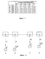
Figure 1 is a database example comprising the distance and angle values along with detected results under the testing process for use in a preferred system embodiment according to the subject method. -
Figure 2 gives some exemplary steps under the testing process. -
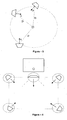
Figure 3 illustrates the possibility that sound sources with the same detected angular values may have many different locations and different angular positions. (The detected angle is the angle between the normal line of the sound source and the line passing through the sound source's center and the sensor) -
Figure 4 illustrates the expected locations and expected directions of sound sources in a sound system. -
Figure 5 illustrates a method for determining the sound source's location and angular position by combining the different distance and angular values originating from two sensors. - The subject method is based on calculating the distance of a sound source in a sound system to a detection centre or to at least one sensor, or the location of such sound source to the detection centre or to at least one sensor, and on determining the angular position of the sound source by making use of such calculated distance or location information and the detected signal response provided in a pre-established database. Said database comprises detected signal response data obtained from previously conducted tests for a given sound source, the distances used in said test process, and the angular position data of the sound source matching to such information. Thanks to this method, the angular positions of sound sources included within said sound system are accurately determined.
- This method provides a basis for processes to be executed for enhancing the sound quality of a sound system, and by determining the angular position of the sound source according to the present invention, the actual directions of sound system components are detected so that a full control is provided for the sound system over the sound propagation area.
- An exemplary database comprising the distance and angle values along with detected results under the testing process for use in a preferred system embodiment according to the subject method is given in
Figure 1 . - The distance data (D1, D2, D3, D4, D5) in
Figure 1 refers to the distance between the sensor and the sound source according to how such sources are positioned during the testing process; the angle data (A1, A2, A3, A4, A5) refers to the angle between the normal line of the sound source and the line passing through the sound source's center and the sensor; and the signal responses detected by the sensor (C1, C2, ..., C25) refer to the data to be used together with the distance data in angular position determining process according to the present invention. The storage of the data in table form facilitates the access to the said data. The processing time in the current system is reduced with this respect, - These data may vary according to the detection method. Such data (C1, C2, ..., C25) are not limited to those disclosed, and may further comprise data on amplitude, frequency response, signal characteristics, the ratio between detected signal responses when more than one sound is used at different frequencies during the angular position determination, and the combination thereof. In order to calculate the ratio of the detected signal responses, distinct sounds with different frequencies (e.g. low frequency, high frequency, etc.) are output from the sound source so that the amplitudes of such different sounds as detected by the sensor are compared.
- Said testing process is composed of the following steps as illustrated in
Figure 2 : - 1- The sound source is positioned at a certain distance (D1) to the sensor. (
Figure 2 - A ) - 2- The angle (A1) between the normal line of the sound source and the line passing through the sound source's center and the sensor is determined. (
Figure 2 - B ) - 3- The signal response (C1) detected by the sensor for the sound output from the sound source is determined.
- 4- The procedure is repeated for the distance and angular positions to be measured. (
Figure 2 - C, D ) - The distance, angle, and detected signal response data obtained by such measurements are used to acquire the data to be stored in the database, which will then be used for determining the location and angular position of sound sources in a sound system.
- The higher the number of measured distance and angular data in the testing process, the closer will be the location and angular position data to the real data of a sound source to be detected according to the subject method.
- The data present in the database may not always provide one-to-one matches with the signal responses detected while the sound source's location and angular position is determined. This case may be eliminated by correlating the data in the database to the detected signal response through a mathematical function.
- The database used in determining the angular position is composed of the distance, sound characteristics, and angular position information used in the testing process.
- As obvious, the test measurement data of a sound source can be determined previously. Therefore such generated database shall be peculiar to such sound source on which the measurements were performed. Separate tests must be conducted for each individual element in the sound system and these data must be kept in special databases for sound sources on which relevant measurements are made.
- In the state of the art, several methods are known for determining the location and angular position. The basic principle to be used in such methods is analogues to the procedure implemented during the testing process. Accordingly, steps of the one of the exemplary method are outlined as following:
- 1- The starting time of the sound output is detected by making use of a reference as the sound source outputs the sound.
- 2- The arrival time of the sound as detected by the sensor is compared to the sound's output time so that the sound's arrival time is determined.
- 3- The distance between the sound source and the sensor is determined by making use of the sound's arrival time.
- 4- The angular value matching to this data within the database is detected by referring to the signal response detected by the sensor and to the distance information.
- Concerning the above given processes, only one sensor and only one sound source are taken into account. The data to be acquired by said process is the distance between the sound source and the sensor, and the angle between the normal line of the sound source and the line passing through the sound source's center and the sensor. As illustrated in
Figure 3 , the distance (D) and angle (A) data alone are not adequate for determining the location and angular position. There are many different locations and different angular positions present within the same distance with the same detected angular value. - In order to overcome said problem, either a process may be executed based on some acceptance and assumptions, or the number of sensors may be increased.
- If there are location and angular position assumptions available for the sound source, any detection to be conducted by means of a single sensor, and the calculations to be based on such detection shall suffice in determining the angular positions of sound sources.
- Such assumptions may be in the form of the expected locations and expected angular positions of a sound source, as depicted in
Figure 4 . - In case the subject method is adapted to home cinema systems, said assumptions can conveniently be made. As is known, the aim in home cinema systems is to optimize the sound quality at a certain location by using a plurality of speakers. Previously determined locations such as the front-rear, right-left and the center are availed for this purpose. Nevertheless, it is a preference to face or to direct the speakers within such home cinema systems to the center of such location of optimization.
- Two sensors are provided in an exemplary system according to the present invention. Thus, the distance and angular position data from a single sensor that would be inadequate in exactly determining the location and angle data are made adequate when the different values acquired from both sensors are combined.
- As illustrated in
Figure 5 , the distance D and angle A detected by the first sensor are coincided with the distance D' and angle A' determined by the second sensor so that the location of the sound source and the angular position are determined. - As a different method according to the present invention, three or more sensors are utilized to determine the location and angular position of the sound source. In this manner, the location and angular position of a sound source as determined on a two-dimensional space by means of two sensors may be transferred to a three-dimension space. In a system employing three sensors, there shall be left two potential positions for a sound source measured at the three-dimensional space by combining the data obtained from and calculated for each separate sensor. These two positions may be reduced to a single and absolute position by means of an assumption.
- A system employing four sensors, on the other hand, shall suffice in determining the single and real location and angular position of a sound source measured in the three-dimensional space, without necessitating any assumptions. Such an absolute location and angular position can also be determined by using the forth sensor only for the direction parameter, in place of subjecting it to angular position and distance determination calculations.
- In addition, with some acceptance and assumptions, two sensors or one sensor are sufficient, as well. Although two sensors are used in the sample system of the invention, the angular position of the signal source is determined in the present method which is applied with only one sensor with some acceptance and assumptions in the known home cinema systems.
- Even if the method according to the present invention system is developed to determine the angular positions of sound sources within sound systems for end users, the same method can also be employed for determining the angular position of any sound source. Such exemplary uses may include, but not restricted to determining the direction of the barrel projecting bullets, missiles etc., the direction of a moving vehicle etc..
- When the sensors are properly selected within the subject method, the direction of signal sources radiating electromagnetic waves -beside the angular positions of sound sources- can also be detected.
Claims (2)
- A method for determining the angular position of a sound source comprising the steps of;• establishing a database by means of a testing procedure, said establishing comprising the steps of,○ positioning the sound source at a certain distance to a sensor, and with a certain angle between the normal line of the sound source and the line passing through the sound source's center and the sensor○ detecting the signal response by the sensor for the sound output from the sound source○ repeating at least one time said positioning and detecting steps for a set of different distances and different angles○ establishing the database comprising said distances and angles values along with the signal responses detected for each combination of distances and angles• calculating the distance between the sound source and at least one sensor, or the position of the sound source with respect to at least one sensor;• detecting the signal response by the at least one sensor for the sound output from the sound source; and• determining the angle between the normal line of the sound source and the line passing through the sound source's center and the sensor by comparing said detected signal response with the signal responses provided in the database, an by making use of said calculated distance or location information.
- The method according to Claim 1, wherein only one sensor is used and wherein the data associated with signal responses detected by said sensor and the data in said database are compared to determine the angular position of said sound source.
Applications Claiming Priority (1)
| Application Number | Priority Date | Filing Date | Title |
|---|---|---|---|
| TR2007/00762A TR200700762A2 (en) | 2007-02-09 | 2007-02-09 | Method for determining the angular position of an audio source |
Publications (3)
| Publication Number | Publication Date |
|---|---|
| EP1956868A2 EP1956868A2 (en) | 2008-08-13 |
| EP1956868A3 EP1956868A3 (en) | 2009-03-04 |
| EP1956868B1 true EP1956868B1 (en) | 2014-03-26 |
Family
ID=39400387
Family Applications (1)
| Application Number | Title | Priority Date | Filing Date |
|---|---|---|---|
| EP08101407.8A Active EP1956868B1 (en) | 2007-02-09 | 2008-02-08 | Method for determining the angular position of a sound source |
Country Status (3)
| Country | Link |
|---|---|
| EP (1) | EP1956868B1 (en) |
| ES (1) | ES2464991T3 (en) |
| TR (1) | TR200700762A2 (en) |
Families Citing this family (1)
| Publication number | Priority date | Publication date | Assignee | Title |
|---|---|---|---|---|
| CN114035156B (en) * | 2021-11-08 | 2024-08-23 | 冠捷显示科技(厦门)有限公司 | Combined calculation method for enhancing sound positioning and detecting range |
Family Cites Families (8)
| Publication number | Priority date | Publication date | Assignee | Title |
|---|---|---|---|---|
| WO1993007602A1 (en) | 1991-10-03 | 1993-04-15 | Thomson Consumer Electronics S.A. | Method and arrangement for an angle-depended remote control |
| JP2000050141A (en) | 1998-07-30 | 2000-02-18 | Minolta Co Ltd | Digital camera |
| US6469732B1 (en) | 1998-11-06 | 2002-10-22 | Vtel Corporation | Acoustic source location using a microphone array |
| US6895378B1 (en) * | 2000-09-22 | 2005-05-17 | Meyer Sound Laboratories, Incorporated | System and method for producing acoustic response predictions via a communications network |
| US6730582B2 (en) | 2000-12-21 | 2004-05-04 | Texas Instruments Incorporated | Transistor circuit with varying resistance lightly doped diffused regions for electrostatic discharge (ESD) protection |
| JP4247002B2 (en) | 2003-01-22 | 2009-04-02 | 富士通株式会社 | Speaker distance detection apparatus and method using microphone array, and voice input / output apparatus using the apparatus |
| JP4765289B2 (en) | 2003-12-10 | 2011-09-07 | ソニー株式会社 | Method for detecting positional relationship of speaker device in acoustic system, acoustic system, server device, and speaker device |
| US7949139B2 (en) | 2004-09-23 | 2011-05-24 | Cirrus Logic, Inc. | Technique for subwoofer distance measurement |
-
2007
- 2007-02-09 TR TR2007/00762A patent/TR200700762A2/en unknown
-
2008
- 2008-02-08 ES ES08101407T patent/ES2464991T3/en active Active
- 2008-02-08 EP EP08101407.8A patent/EP1956868B1/en active Active
Non-Patent Citations (1)
| Title |
|---|
| DANIELE PONTEGGIA: "How to create ease loudspeaker models using clio", 26 October 2006 (2006-10-26), Retrieved from the Internet <URL:http://web.archive.org/web/20061026191301/http://www.audiomatica.com/download/polar_measurements_and_ease+.pdf> [retrieved on 20100730] * |
Also Published As
| Publication number | Publication date |
|---|---|
| ES2464991T3 (en) | 2014-06-04 |
| EP1956868A3 (en) | 2009-03-04 |
| TR200700762A2 (en) | 2008-09-22 |
| EP1956868A2 (en) | 2008-08-13 |
Similar Documents
| Publication | Publication Date | Title |
|---|---|---|
| US10972835B2 (en) | Conference system with a microphone array system and a method of speech acquisition in a conference system | |
| US7586513B2 (en) | Arrangement and method for audio source tracking | |
| CN105659109B (en) | Navigation and integrality monitoring | |
| US20100008515A1 (en) | Multiple acoustic threat assessment system | |
| EP2810453B1 (en) | Audio source position estimation | |
| CA2662946A1 (en) | Method and device for determining a location of a communications device | |
| Gala et al. | Realtime active sound source localization for unmanned ground robots using a self-rotational bi-microphone array | |
| KR101697696B1 (en) | Method and Apparatus for Finding Direction Using Directional Antennas | |
| EP3048817A1 (en) | Method of determining acoustical characteristics of a room or venue having n sound sources | |
| Gaubitch et al. | Calibration of distributed sound acquisition systems using TOA measurements from a moving acoustic source | |
| KR20090128221A (en) | Sound source location estimation method and system according to the method | |
| Pertilä et al. | Closed-form self-localization of asynchronous microphone arrays | |
| KR101581619B1 (en) | Sound Collecting Terminal, Sound Providing Terminal, Sound Data Processing Server and Sound Data Processing System using thereof | |
| CN112119642B (en) | Acoustic system and related localization method for detection and localization of low-intensity and low-frequency sound sources | |
| KR101616361B1 (en) | Apparatus and method for estimating location of long-range acoustic target | |
| US10104489B2 (en) | Method for using a mobile device equipped with at least two microphones for determining the direction of loudspeakers in a setup of a surround sound system | |
| EP1956868A2 (en) | Method for determining the angular position of a sound source | |
| Tervo et al. | Acoustic reflection path tracing using a highly directional loudspeaker | |
| KR101673812B1 (en) | Sound Collecting Terminal, Sound Providing Terminal, Sound Data Processing Server and Sound Data Processing System using thereof | |
| Rizzo et al. | Localization of sound sources by means of unidirectional microphones | |
| KR102180229B1 (en) | Apparatus for Estimating Sound Source Localization and Robot Having The Same | |
| KR20060124443A (en) | Sound Source Location Estimation Using Head Transfer Function Database | |
| CN113543306A (en) | Method and device for determining the position of a mobile subscriber, subscriber of a wireless communication network, remotely located network element, wireless communication network | |
| Lu et al. | Geometric Calibration of Distributed Microphone Arrays Based on Cross-Correlation Function | |
| Ikeda et al. | 2D Sound Source Localization in Azimuth & Elevation from Microphone Array by Using a Directional Pattern of Element |
Legal Events
| Date | Code | Title | Description |
|---|---|---|---|
| PUAI | Public reference made under article 153(3) epc to a published international application that has entered the european phase |
Free format text: ORIGINAL CODE: 0009012 |
|
| 17P | Request for examination filed |
Effective date: 20080304 |
|
| AK | Designated contracting states |
Kind code of ref document: A2 Designated state(s): AT BE BG CH CY CZ DE DK EE ES FI FR GB GR HR HU IE IS IT LI LT LU LV MC MT NL NO PL PT RO SE SI SK TR |
|
| AX | Request for extension of the european patent |
Extension state: AL BA MK RS |
|
| PUAL | Search report despatched |
Free format text: ORIGINAL CODE: 0009013 |
|
| AK | Designated contracting states |
Kind code of ref document: A3 Designated state(s): AT BE BG CH CY CZ DE DK EE ES FI FR GB GR HR HU IE IS IT LI LT LU LV MC MT NL NO PL PT RO SE SI SK TR |
|
| AX | Request for extension of the european patent |
Extension state: AL BA MK RS |
|
| AKX | Designation fees paid |
Designated state(s): AT BE BG CH CY CZ DE DK EE ES FI FR GB GR HR HU IE IS IT LI LT LU LV MC MT NL NO PL PT RO SE SI SK TR |
|
| 17Q | First examination report despatched |
Effective date: 20091015 |
|
| GRAP | Despatch of communication of intention to grant a patent |
Free format text: ORIGINAL CODE: EPIDOSNIGR1 |
|
| INTG | Intention to grant announced |
Effective date: 20131017 |
|
| GRAS | Grant fee paid |
Free format text: ORIGINAL CODE: EPIDOSNIGR3 |
|
| GRAA | (expected) grant |
Free format text: ORIGINAL CODE: 0009210 |
|
| AK | Designated contracting states |
Kind code of ref document: B1 Designated state(s): AT BE BG CH CY CZ DE DK EE ES FI FR GB GR HR HU IE IS IT LI LT LU LV MC MT NL NO PL PT RO SE SI SK TR |
|
| REG | Reference to a national code |
Ref country code: GB Ref legal event code: FG4D |
|
| REG | Reference to a national code |
Ref country code: CH Ref legal event code: EP |
|
| REG | Reference to a national code |
Ref country code: AT Ref legal event code: REF Ref document number: 659494 Country of ref document: AT Kind code of ref document: T Effective date: 20140415 |
|
| REG | Reference to a national code |
Ref country code: IE Ref legal event code: FG4D |
|
| REG | Reference to a national code |
Ref country code: DE Ref legal event code: R096 Ref document number: 602008031078 Country of ref document: DE Effective date: 20140508 |
|
| REG | Reference to a national code |
Ref country code: ES Ref legal event code: FG2A Ref document number: 2464991 Country of ref document: ES Kind code of ref document: T3 Effective date: 20140604 |
|
| PG25 | Lapsed in a contracting state [announced via postgrant information from national office to epo] |
Ref country code: LT Free format text: LAPSE BECAUSE OF FAILURE TO SUBMIT A TRANSLATION OF THE DESCRIPTION OR TO PAY THE FEE WITHIN THE PRESCRIBED TIME-LIMIT Effective date: 20140326 Ref country code: NO Free format text: LAPSE BECAUSE OF FAILURE TO SUBMIT A TRANSLATION OF THE DESCRIPTION OR TO PAY THE FEE WITHIN THE PRESCRIBED TIME-LIMIT Effective date: 20140626 |
|
| REG | Reference to a national code |
Ref country code: AT Ref legal event code: MK05 Ref document number: 659494 Country of ref document: AT Kind code of ref document: T Effective date: 20140326 |
|
| REG | Reference to a national code |
Ref country code: NL Ref legal event code: VDEP Effective date: 20140326 |
|
| REG | Reference to a national code |
Ref country code: LT Ref legal event code: MG4D |
|
| PG25 | Lapsed in a contracting state [announced via postgrant information from national office to epo] |
Ref country code: FI Free format text: LAPSE BECAUSE OF FAILURE TO SUBMIT A TRANSLATION OF THE DESCRIPTION OR TO PAY THE FEE WITHIN THE PRESCRIBED TIME-LIMIT Effective date: 20140326 Ref country code: SE Free format text: LAPSE BECAUSE OF FAILURE TO SUBMIT A TRANSLATION OF THE DESCRIPTION OR TO PAY THE FEE WITHIN THE PRESCRIBED TIME-LIMIT Effective date: 20140326 |
|
| PG25 | Lapsed in a contracting state [announced via postgrant information from national office to epo] |
Ref country code: HR Free format text: LAPSE BECAUSE OF FAILURE TO SUBMIT A TRANSLATION OF THE DESCRIPTION OR TO PAY THE FEE WITHIN THE PRESCRIBED TIME-LIMIT Effective date: 20140326 Ref country code: LV Free format text: LAPSE BECAUSE OF FAILURE TO SUBMIT A TRANSLATION OF THE DESCRIPTION OR TO PAY THE FEE WITHIN THE PRESCRIBED TIME-LIMIT Effective date: 20140326 |
|
| PG25 | Lapsed in a contracting state [announced via postgrant information from national office to epo] |
Ref country code: CZ Free format text: LAPSE BECAUSE OF FAILURE TO SUBMIT A TRANSLATION OF THE DESCRIPTION OR TO PAY THE FEE WITHIN THE PRESCRIBED TIME-LIMIT Effective date: 20140326 Ref country code: BE Free format text: LAPSE BECAUSE OF FAILURE TO SUBMIT A TRANSLATION OF THE DESCRIPTION OR TO PAY THE FEE WITHIN THE PRESCRIBED TIME-LIMIT Effective date: 20140326 Ref country code: RO Free format text: LAPSE BECAUSE OF FAILURE TO SUBMIT A TRANSLATION OF THE DESCRIPTION OR TO PAY THE FEE WITHIN THE PRESCRIBED TIME-LIMIT Effective date: 20140326 Ref country code: BG Free format text: LAPSE BECAUSE OF FAILURE TO SUBMIT A TRANSLATION OF THE DESCRIPTION OR TO PAY THE FEE WITHIN THE PRESCRIBED TIME-LIMIT Effective date: 20140626 Ref country code: EE Free format text: LAPSE BECAUSE OF FAILURE TO SUBMIT A TRANSLATION OF THE DESCRIPTION OR TO PAY THE FEE WITHIN THE PRESCRIBED TIME-LIMIT Effective date: 20140326 Ref country code: NL Free format text: LAPSE BECAUSE OF FAILURE TO SUBMIT A TRANSLATION OF THE DESCRIPTION OR TO PAY THE FEE WITHIN THE PRESCRIBED TIME-LIMIT Effective date: 20140326 Ref country code: CY Free format text: LAPSE BECAUSE OF FAILURE TO SUBMIT A TRANSLATION OF THE DESCRIPTION OR TO PAY THE FEE WITHIN THE PRESCRIBED TIME-LIMIT Effective date: 20140326 Ref country code: IS Free format text: LAPSE BECAUSE OF FAILURE TO SUBMIT A TRANSLATION OF THE DESCRIPTION OR TO PAY THE FEE WITHIN THE PRESCRIBED TIME-LIMIT Effective date: 20140726 |
|
| PG25 | Lapsed in a contracting state [announced via postgrant information from national office to epo] |
Ref country code: PL Free format text: LAPSE BECAUSE OF FAILURE TO SUBMIT A TRANSLATION OF THE DESCRIPTION OR TO PAY THE FEE WITHIN THE PRESCRIBED TIME-LIMIT Effective date: 20140326 Ref country code: SK Free format text: LAPSE BECAUSE OF FAILURE TO SUBMIT A TRANSLATION OF THE DESCRIPTION OR TO PAY THE FEE WITHIN THE PRESCRIBED TIME-LIMIT Effective date: 20140326 Ref country code: AT Free format text: LAPSE BECAUSE OF FAILURE TO SUBMIT A TRANSLATION OF THE DESCRIPTION OR TO PAY THE FEE WITHIN THE PRESCRIBED TIME-LIMIT Effective date: 20140326 |
|
| PG25 | Lapsed in a contracting state [announced via postgrant information from national office to epo] |
Ref country code: PT Free format text: LAPSE BECAUSE OF FAILURE TO SUBMIT A TRANSLATION OF THE DESCRIPTION OR TO PAY THE FEE WITHIN THE PRESCRIBED TIME-LIMIT Effective date: 20140728 |
|
| REG | Reference to a national code |
Ref country code: DE Ref legal event code: R097 Ref document number: 602008031078 Country of ref document: DE |
|
| PG25 | Lapsed in a contracting state [announced via postgrant information from national office to epo] |
Ref country code: DK Free format text: LAPSE BECAUSE OF FAILURE TO SUBMIT A TRANSLATION OF THE DESCRIPTION OR TO PAY THE FEE WITHIN THE PRESCRIBED TIME-LIMIT Effective date: 20140326 |
|
| PLBE | No opposition filed within time limit |
Free format text: ORIGINAL CODE: 0009261 |
|
| STAA | Information on the status of an ep patent application or granted ep patent |
Free format text: STATUS: NO OPPOSITION FILED WITHIN TIME LIMIT |
|
| 26N | No opposition filed |
Effective date: 20150106 |
|
| REG | Reference to a national code |
Ref country code: DE Ref legal event code: R097 Ref document number: 602008031078 Country of ref document: DE Effective date: 20150106 |
|
| PG25 | Lapsed in a contracting state [announced via postgrant information from national office to epo] |
Ref country code: SI Free format text: LAPSE BECAUSE OF FAILURE TO SUBMIT A TRANSLATION OF THE DESCRIPTION OR TO PAY THE FEE WITHIN THE PRESCRIBED TIME-LIMIT Effective date: 20140326 |
|
| PG25 | Lapsed in a contracting state [announced via postgrant information from national office to epo] |
Ref country code: LU Free format text: LAPSE BECAUSE OF FAILURE TO SUBMIT A TRANSLATION OF THE DESCRIPTION OR TO PAY THE FEE WITHIN THE PRESCRIBED TIME-LIMIT Effective date: 20150208 |
|
| REG | Reference to a national code |
Ref country code: CH Ref legal event code: PL |
|
| PG25 | Lapsed in a contracting state [announced via postgrant information from national office to epo] |
Ref country code: MC Free format text: LAPSE BECAUSE OF FAILURE TO SUBMIT A TRANSLATION OF THE DESCRIPTION OR TO PAY THE FEE WITHIN THE PRESCRIBED TIME-LIMIT Effective date: 20140326 Ref country code: CH Free format text: LAPSE BECAUSE OF NON-PAYMENT OF DUE FEES Effective date: 20150228 Ref country code: LI Free format text: LAPSE BECAUSE OF NON-PAYMENT OF DUE FEES Effective date: 20150228 |
|
| REG | Reference to a national code |
Ref country code: IE Ref legal event code: MM4A |
|
| REG | Reference to a national code |
Ref country code: FR Ref legal event code: PLFP Year of fee payment: 9 |
|
| PG25 | Lapsed in a contracting state [announced via postgrant information from national office to epo] |
Ref country code: IE Free format text: LAPSE BECAUSE OF NON-PAYMENT OF DUE FEES Effective date: 20150208 |
|
| PG25 | Lapsed in a contracting state [announced via postgrant information from national office to epo] |
Ref country code: GR Free format text: LAPSE BECAUSE OF FAILURE TO SUBMIT A TRANSLATION OF THE DESCRIPTION OR TO PAY THE FEE WITHIN THE PRESCRIBED TIME-LIMIT Effective date: 20140627 |
|
| REG | Reference to a national code |
Ref country code: FR Ref legal event code: PLFP Year of fee payment: 10 |
|
| PG25 | Lapsed in a contracting state [announced via postgrant information from national office to epo] |
Ref country code: MT Free format text: LAPSE BECAUSE OF FAILURE TO SUBMIT A TRANSLATION OF THE DESCRIPTION OR TO PAY THE FEE WITHIN THE PRESCRIBED TIME-LIMIT Effective date: 20140326 |
|
| PG25 | Lapsed in a contracting state [announced via postgrant information from national office to epo] |
Ref country code: HU Free format text: LAPSE BECAUSE OF FAILURE TO SUBMIT A TRANSLATION OF THE DESCRIPTION OR TO PAY THE FEE WITHIN THE PRESCRIBED TIME-LIMIT; INVALID AB INITIO Effective date: 20080208 |
|
| REG | Reference to a national code |
Ref country code: FR Ref legal event code: PLFP Year of fee payment: 11 |
|
| REG | Reference to a national code |
Ref country code: DE Ref legal event code: R082 Ref document number: 602008031078 Country of ref document: DE Representative=s name: LEONHARD, REIMUND, DIPL.-ING., DE |
|
| PGFP | Annual fee paid to national office [announced via postgrant information from national office to epo] |
Ref country code: FR Payment date: 20230220 Year of fee payment: 16 |
|
| PGFP | Annual fee paid to national office [announced via postgrant information from national office to epo] |
Ref country code: IT Payment date: 20230223 Year of fee payment: 16 Ref country code: GB Payment date: 20230220 Year of fee payment: 16 Ref country code: DE Payment date: 20230216 Year of fee payment: 16 |
|
| PGFP | Annual fee paid to national office [announced via postgrant information from national office to epo] |
Ref country code: ES Payment date: 20230424 Year of fee payment: 16 |
|
| REG | Reference to a national code |
Ref country code: DE Ref legal event code: R119 Ref document number: 602008031078 Country of ref document: DE |
|
| GBPC | Gb: european patent ceased through non-payment of renewal fee |
Effective date: 20240208 |
|
| PG25 | Lapsed in a contracting state [announced via postgrant information from national office to epo] |
Ref country code: DE Free format text: LAPSE BECAUSE OF NON-PAYMENT OF DUE FEES Effective date: 20240903 |
|
| PG25 | Lapsed in a contracting state [announced via postgrant information from national office to epo] |
Ref country code: GB Free format text: LAPSE BECAUSE OF NON-PAYMENT OF DUE FEES Effective date: 20240208 |
|
| PG25 | Lapsed in a contracting state [announced via postgrant information from national office to epo] |
Ref country code: FR Free format text: LAPSE BECAUSE OF NON-PAYMENT OF DUE FEES Effective date: 20240229 |
|
| PG25 | Lapsed in a contracting state [announced via postgrant information from national office to epo] |
Ref country code: GB Free format text: LAPSE BECAUSE OF NON-PAYMENT OF DUE FEES Effective date: 20240208 Ref country code: FR Free format text: LAPSE BECAUSE OF NON-PAYMENT OF DUE FEES Effective date: 20240229 Ref country code: DE Free format text: LAPSE BECAUSE OF NON-PAYMENT OF DUE FEES Effective date: 20240903 |
|
| PG25 | Lapsed in a contracting state [announced via postgrant information from national office to epo] |
Ref country code: IT Free format text: LAPSE BECAUSE OF NON-PAYMENT OF DUE FEES Effective date: 20240208 |
|
| REG | Reference to a national code |
Ref country code: ES Ref legal event code: FD2A Effective date: 20250327 |
|
| PG25 | Lapsed in a contracting state [announced via postgrant information from national office to epo] |
Ref country code: ES Free format text: LAPSE BECAUSE OF NON-PAYMENT OF DUE FEES Effective date: 20240209 |
|
| PGFP | Annual fee paid to national office [announced via postgrant information from national office to epo] |
Ref country code: TR Payment date: 20260206 Year of fee payment: 19 |