EP1956728A2 - Method for controlling communication of radio terminal, and radio terminal - Google Patents
Method for controlling communication of radio terminal, and radio terminal Download PDFInfo
- Publication number
- EP1956728A2 EP1956728A2 EP07123869A EP07123869A EP1956728A2 EP 1956728 A2 EP1956728 A2 EP 1956728A2 EP 07123869 A EP07123869 A EP 07123869A EP 07123869 A EP07123869 A EP 07123869A EP 1956728 A2 EP1956728 A2 EP 1956728A2
- Authority
- EP
- European Patent Office
- Prior art keywords
- transmission
- base station
- radio base
- transmission power
- uplink
- Prior art date
- Legal status (The legal status is an assumption and is not a legal conclusion. Google has not performed a legal analysis and makes no representation as to the accuracy of the status listed.)
- Granted
Links
Images


Classifications
-
- H—ELECTRICITY
- H04—ELECTRIC COMMUNICATION TECHNIQUE
- H04W—WIRELESS COMMUNICATION NETWORKS
- H04W52/00—Power management, e.g. TPC [Transmission Power Control], power saving or power classes
- H04W52/04—TPC
- H04W52/06—TPC algorithms
- H04W52/16—Deriving transmission power values from another channel
-
- H—ELECTRICITY
- H04—ELECTRIC COMMUNICATION TECHNIQUE
- H04W—WIRELESS COMMUNICATION NETWORKS
- H04W52/00—Power management, e.g. TPC [Transmission Power Control], power saving or power classes
- H04W52/04—TPC
- H04W52/06—TPC algorithms
- H04W52/14—Separate analysis of uplink or downlink
- H04W52/146—Uplink power control
-
- H—ELECTRICITY
- H04—ELECTRIC COMMUNICATION TECHNIQUE
- H04W—WIRELESS COMMUNICATION NETWORKS
- H04W52/00—Power management, e.g. TPC [Transmission Power Control], power saving or power classes
- H04W52/04—TPC
- H04W52/18—TPC being performed according to specific parameters
- H04W52/28—TPC being performed according to specific parameters using user profile, e.g. mobile speed, priority or network state, e.g. standby, idle or non transmission
- H04W52/286—TPC being performed according to specific parameters using user profile, e.g. mobile speed, priority or network state, e.g. standby, idle or non transmission during data packet transmission, e.g. high speed packet access [HSPA]
-
- H—ELECTRICITY
- H04—ELECTRIC COMMUNICATION TECHNIQUE
- H04W—WIRELESS COMMUNICATION NETWORKS
- H04W52/00—Power management, e.g. TPC [Transmission Power Control], power saving or power classes
- H04W52/04—TPC
- H04W52/38—TPC being performed in particular situations
- H04W52/44—TPC being performed in particular situations in connection with interruption of transmission
Definitions
- the present invention relates to a method for controlling communication of a radio terminal and the radio terminal preferably used in a radio communication system performs communication in, for example, W-CDMA (Wideband-Code Division Multiple Access) method.
- W-CDMA Wideband-Code Division Multiple Access
- W-CDMA is one of the radio communication interfaces definedbyIMT-2000 (International Mobile Telecommunications -2000) and is regarded as a typical radio communication method.
- the maximum transmission rate of 384 kbps of W-CDMA can realize multimedia access for audio, moving image, data and others.
- HSDPA High Speed Downlink Packet Access
- HSUPA High Speed Uplink Packet Access
- HSDPA is a technique for high-speed downlink packet transmission in the direction from a base station to a UE (User Equipment) and HSUPA is a technique for high-speed uplink packet transmission in the reverse direction.
- HSDPA and HSUPA have been standardized by 3GPP Release 5 (3rd Generation Partnership Project Release 5), and 3GPP Release 6, respectively.
- Fig. 2 shows the concept of W-CDMA communication. As shown in Fig. 2 , a radio communication in the W-CDMA method is performed between a radio base station 100 and one or more of UEs 200.
- DPDCH Dedicated Physical Data Channel
- DPCCH Dedicated Physical Control Channel
- I axis the in-phase component
- Q axis the Quadrature component
- QPSK Quadrature Phase Shift Keying
- the DPDCH and the DPCCH are time-division-multiplexed and are transmitted to the UE 200 (see broken arrow A2). These downlink channels are dedicated to each UE 200 and transmission through these channels is performed exclusively of the other UEs 200.
- Fig. 3 shows the concept of HSDPA communication. As shown in Fig. 3 , downlink transmission from the radio base station 100 to the UE 200 is carried out by HSDPA communication.
- each UE 200 receives a pilot signal (known by radio base station 100 and the UE 200) transmitted through a pilot channel (CPICH: Common Pilot Channel) (see reference number A5).
- CPICH Common Pilot Channel
- each UE 200 measures a downlink propagation environment, that is, reception quality (SIR: Signal-to-Interference Ratio), calculates a CQI (Channel Quality Indicator) representing downlink reception quality based on the measured SIR, and notifies the radio base station 100 of the calculated CQI through HS-DPCCH (High Speed Dedicated Physical Control Channel) (see solid arrow A3).
- SIR Signal-to-Interference Ratio
- CQI Channel Quality Indicator
- the radio base station 100 schedules preferential selection of a predetermined number of UEs in a good propagation environment. If a certain UE 200 is selected by the scheduling, the radio base station 100 transmits scheduling information (including the modulation method, the transmission amount, and others) to the UE 200 through HS-SCCH (High Speed Shared Control Channel) (see broken arrow A4).
- the UE 200 determines the functions of the UE 200 itself with reference to the received scheduling information.
- the radio base station 100 transmits user information to the UE 200 through a radio channel called HS-PDSCH (High Speed Physical Downlink Shared Control Channel) (see broken arrow A4).
- HS-PDSCH High Speed Physical Downlink Shared Control Channel
- the HS-PDSCH for transmission of user information is commonly used by all UEs 200, and a single time slot generated by time division is shared by one or more UEs 200 to realize downlink access of 14.4 Mbps at maximum.
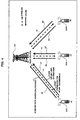
- Fig. 4 shows the concept of HSUPA communication. As shown in Fig. 4 , uplink transmission from the UE 200 to the radio base station 100 is performed by communication HSUPA.
- the UE 200 sends the radio base station 100 SI (Scheduling Information) as a request for uplink data transmission (see solid arrow A6).
- SI Service Information
- the radio base station 100 collects a number of pieces of SI sent from UEs 200, schedules transmission timings for uplink transmission of UEs 200 based on communication quality of each UE 200, data priority and other factors, and finally transmits "Grant” indicating uplink transmission permission to UEs 200 (see broken arrow A7).
- "Grant” is classified into two types of “absolute Grant” and “relative Grant”: “absolute Grant” is used to notify an uplink transmission rate and others at regular intervals and “relative Grant” is used to notify update information of contents notified in the "absolute Grant”.
- UEs 200 transmit user information to the radio base station 100 through channels called E-DCH (Enhanced Dedicated Channel), dedicated one to each UE 200, in order of being permitted transmission in the form of receipt of "Grant" from the radio base station 100(see solid arrow A8) whereby high-speed uplink access is made possible.
- E-DCH Enhanced Dedicated Channel
- the transmission rate through an E-DCH is being examined to be approximately 2-5 Mpbs.
- HSDPA adopts an adaptive coding and modulation method, and is characterized by, for example, switching a modulation method between QPSK modulation and 16QAM modulation according to a radio environment between the radio base station 100 and the UE 200.
- the UE 200 defines the CQI to report the reception environment to the radio base station 100 and a CQI table defines formats different in transmission power which formats vary with the value of the CQI in the range of, for example, from 1 through 30.
- BLER Block Error Rate
- the radio base station 100 monitors the total uplink interference amount (reception power) of controlling UEs 200, and as a result of comparison between the reception power and a threshold, indicates the absolute value of transmission rate using E-AGCH (a command indicating the absolute value of the maximum rate) or indicates increase, holding, or decrease in the transmission power using E-RGCH (a command indicating a relative value of the maximum rate).
- E-AGCH a command indicating the absolute value of the maximum rate
- E-RGCH a command indicating a relative value of the maximum rate
- SI indicates information concerning transmission data that the UE 200 is to transmit which information is exemplified by "highest priority logical channel ID”, “total data amount of all the logical channel”, “total data amount of highest priority logical channel”, and "a transmission power that a UE 200 can transmit” that are mapped on the SI.
- Fig. 6 shows frame formats of E-DPDCH (Enhanced-Dedicated Physical Control Channel) and the E-DPDCH (Enhanced-Dedicated Physical Data Channel) that are dedicated to the E-DCH.
- the E-DCH is formed by two channels of: (1) E-DPCCH for transmission of control information and (2) E-DPDCH for transmission of data.
- the E-DPCCH maps control information (uplink control data) for uplink data such as an E-TFCI (E-DCH Transport Format Combination Indicator), an RSN (Retransmission Sequence Number) and a Happy bit, thereover.
- E-TFCI E-DCH Transport Format Combination Indicator
- RSN Real-Retransmission Sequence Number
- the E-TFCI is information indicating that an uplink radio frame to be transmitted along with the uplink data is mapped over a transport channel
- the RSN is information indicating the number of uplink HARQs (Hybrid Automatic Repeat Requests) transmitted.
- the Happy bit is information indicating whether or not the UE 200 requires additional resource (transmission power resource).
- Patent Reference 1 discloses reduction in a bit number of scheduling information improves the efficiency of communication.
- Non-Patent Reference 1 serves as an exemplary material about a physical channel and a transport channel for W-CDMA including HSUPA.
- Non-Patent References 2 and 3 serve as exemplary materials about a physical layer of HSUPA.
- Patent Reference 1 Japanese Patent Application Laid-Open (KOKAI) No. 2005-6293
- Fig. 5 shows elements of the UE 200 having a function for transmitting the SI (scheduling request) .
- UE 200 shown in Fig. 5 includes, for example, a receiver 201, an HS-SCCH demodulator 202, an HS-SCCH decoder 203, an HS-PBSCH demodulator 204, a CQI reporting value calculator 205, an HS-PDSCH decoder 206, an HS-PDSCH CRC operator 207, a downlink L2 (Layer 2) data processor 208, a downlink reception timing monitoring and uplink transmission timing managing section 209, a CQI/ACK/NACK scheduler 210, an HS-DPCCH encoder 211, an HS-DPCCHmodulator 212, anuplinkL2 (Layer 2) dataprocessor 213, an E-TFCI/RSN/Happy-bit scheduler 214, an E-DPCCH encoder 215, an E-DPCCH modulator 216, an uplink scheduling request processor 217,
- a signal received at a reception antenna is inputted into the receiver 201, where a path detection and an inverse diffusion process are performed to separate the CPICH, the HS-SCCH and the HS-PDSCH from one another.
- the CPICH (a pilot signal) obtained by the separation is inputted into the CQI reporting value calculator 205 to be used for calculating a CQI reporting value.
- a downlink reception SIR is measured in accordance with the received pilot signal and a downlink CQI is calculated considering the result of the measurement.
- the calculated CQI is subjected to an encoding process, a modulation process, and a radio transmission process while passing the CQI/ACK/NACK scheduler (hereinafter also simply called "scheduler") 210, the HS-DPCCH encoder 211, the HS-DPCCH modulator 212, and the transmitter 220, and is then transmitted to the radio base station 100 through the HS-DPCCH.
- the obtained pilot signal is also used to calculate channel estimation values of the HS-SCCH and the HS-PDSCH.
- the HS-SCCH separated in the receiver 201 undergoes a channel compensation using the channel estimation value obtained on the basis of the received pilot signal and then a demodulation in the HS-SCCH demodulator 202, and is decoded in the HS-SCCH decoder 203.
- the result of the decoding includes information (e.g., an encoding method, an encoding ratio) required to decode the HS-PDSCH and is therefore inputted into the HS-PDSCH demodulator 206.
- the HS-PDSCH separated by receiver 201 which has been subjected to a channel compensation using the channel estimation value and demodulation in HS-PDSCH demodulator 204, is decoded in HS-PDSCH decoder 206 using the result of decoding from HS-SCCH decoder 203 and is used for a CRC operation in HS-PDSCH CRC operator 207 for error check.
- the decoded data that has been judged to have no error (CRC operation result of which is OK) is regarded as received data of the downlink layer 2 and is therefore inputted into the downlink L2 data processor 208, where a predetermined data processing is performed on the decoded data.
- the result of the CRC operation is inputted into the scheduler 210, which schedules, along with the CQI reporting value, reception result information of ACK (Acknowledgment) or NACK(Negative Acknowledgment) respectively corresponding to the CRC-operation result being OK or NG.
- the CRC-operation result is then subjected to an encoding process, a modulating process and a radio transmission process while passing the HS-DPCCH encoder 211, the HS-DPCCH modulator 212, and the transmitter 220, and is finally notified to the radio base station 100 through the HS-DPCCH.
- the E-TFCI/RSN/Happy bit scheduler 214 generates uplink control data, which undergoes an encoding process, a modulation process and a radio transmission process while passing the E-DPCCH encoder 215, the E-DPCCH modulator 216, and the transmitter 220 and is transmitted to the radio base station 100 through the E-DPCCH.
- the uplink scheduling request processor 217 generates uplink SI, on which an encoding process and a modulating process and a radio transmission process are performed in the E-DPDCH encoder 218, the E-DPDCH modulator 219, and the transmitter 220 and which is consequently transmitted to the radio base station 100 through the E-DPDCH.
- the transmission timings of the HS-DPCCH, the E-DPCCH, and the E-DPDCH from the transmitter 220 are managed in accordance with a transmission timing signal from the downlink reception timing monitoring and uplink transmission timing managing section 209 (hereinafter simply called "timing management section").
- the timing management section 209 manages transmission timings (transmission slots) of the HS-DPCCH, the E-DPCCH, and the E-DPDCH with reference to reception timings (frame timings) specified by a frame synchronization process performed in the receiver 201, and controls the transmission timing of the transmitter 220 to be a predetermined timing in accordance with the transmission timing in question.
- Fig. 7 is a diagram illustrating a digit of the Happy bit.
- the Happy bit transmitted through the E-DPCCH indicates either the "Happy state” (Happy bit of "1") in which the UE 200 does not require an additional resource or the "Unhappy state” (Happy bit of "0") in which the UE 200 requires an additional resource. If all the three following conditions are satisfied, the "Not happy (Unhappy) state" representing a requirement for an additional resource is notified to the radio base station 100.
- the communication environment (communication quality) between the radio base station 100 and the UE 200 does not satisfy a certain level while the UE 200 nevertheless transmits uplink data to the radio base station through the E-DPDCH at the maximum transmission power
- a lack of an uplink transmission rate may fail in completion of transmitting of all uplink data.
- the above case dissatisfies the condition (2) that "UE can use sufficient power that allows transmission at a higher data rate.”
- the UE 200 notifies the radio base station 100 of the "Happy state” indicating not requiring the additional resource, and cannot request the radio base station 100 for allocation of the additional resource. That may cause a problem that transmission of uplink data cannot be normally completed.
- Desirable features of the present invention may include the following, either selectively or in combination.
- Fig. 1 is a block diagram schematically illustrating a radio terminal (UE) according to the first embodiment of the present invention.
- UE 1 shown in Fig. 1 includes, for example, a receiver 2, an HS-SCCH demodulator 3, an HS-SCCH decoder 4, an HS-PDSCH demodulator 5, a CQI reporting value calculator 6, an HS-PDSCH decoder 7, an HS-PDSCH CRC operator 8, a downlink L2 (Layer 2) data processor 9, a downlink reception timing monitoring and uplink transmission timing managing section 10, a CQI/ACK/NACK scheduler 11, an HS-DPCCH encoder 12, an HS-DPCCH modulator 13, an uplink L2 (Layer 2) data processor 14, an E-TFCI/RSN/Happy-bit scheduler 15, an E-DPCCH encoder 16, an E-DPCCH modulator 17, an uplink scheduling request processor 18, an E-DPDCH encoder 19, an E-DPDCH modulator 20, a transmitter 21, an ACK/NACK/CQI
- the UE 1 communicates with a radio base station 30 at transmission power granted by the radio base station 30 at a request (of the UE 1) to the radio base station 30, and includes new elements of the ACK/NACK/CQI/DTX controller 22 and the Happy condition signal monitor 23 in addition to the elements incorporated in a conventional radio terminal.
- the receiver 2 performs a path detection and an inverse diffusion process responsive to receipt of a signal at a reception antenna (not shown) and separates channels of the CPICH, the HS-SCCH and the HS-PDSCH from one another.
- the CQI reporting value calculator 6 calculate a CQI reporting value based on the CPICH (pilot signal) separated by the receiver 2, and more specifically measures a downlink reception SIRbased on the receivedpilot signal and calculates a downlink CQI based on the result of the measurement.
- a CQI calculated by the CQI reporting value calculator 6 is subjected to an encoding process, a modulation process, and a radio transmission process while passing the CQI/ACK/NACK scheduler (hereinafter also simply called "scheduler") 11, the HS-DPCCH encoder 12, the HS-DPCCH modulator 13, and the transmitter 21, and is then transmitted to the radio base station 30 through the HS-DPCCH.
- the received pilot signal is also used to calculate channel estimation values of the HS-SCCH and the HS-PDSCH.
- the HS-SCCH demodulator 3 performs a channel compensation using a channel estimation value obtained in accordance with the received pilot signal on the HS-SCCH separated by the receiver 2 and then demodulates the compensated HS-SCCH.
- the HS-SCCH decoder 4 decodes the HS-SCCH from the HS-SCCH demodulator 3.
- the result of decoding in the HS-SCCH decoder 4 includes information (e.g., an encoding method, an encoding ratio) required to decode the HS-PDSCH and is therefore inputted into the HS-PDSCH demodulator 5.
- the HS-PDSCH demodulator 5 demodulates the HS-PDSCH which has been separated in the receiver 2 and which has undergone a channel compensation using a channel estimating value.
- the HS-PDSCH decoder 7 decodes the received HS-PDSCH using the result of the decoding in the HS-SCCH decoder 4.
- the HS-PDSCH CRC operator 8 has a function to perform a CRC operation on the result of the decoding in the HS-PDSCH decoder 7 for error check.
- the downlink L2 data processor 9 performs a predetermined L2-data process on decoded data that the error check by the HS-PDSCH CRC operator 8 has judged to have no error (CRC operation result of which is OK).
- the reception result information i.e., an ACK or a NACK serving as the CRC operation result is inputted into the ACK/NACK/CQI/DTX controller 22.
- the scheduler 11 schedules transmission processes for various information pieces of an ACK, a NACK, and a CQI reporting value, which are subsequently inputted into the HS-DPCCH encoder 12 where a predetermined transmission process takes place.
- the HS-DPCCH encoder 12 has a function for performing a predetermined encoding process on the information pieces
- the HS-DPCCH modulator 13 has a function for performing a predetermined modulating process on the same information pieces.
- the transmitter 21 carries out a predetermined radio transmission process.
- information output from the ACK/NACK/CQI/DTX controller 22 is notified to the radio base station 30 via the scheduler 11, the HS-DPCCH encoder 12, the HS-DPCCH modulator 13, and the transmitter 21.
- uplink transmission data (uplink data) is generated in the uplink L2 data processor 14.
- the uplink L2 data processor 14 has a function for performing a predetermined L2 process as well as a function for generating uplink L2 data that is to be transmitted to the radio base station 30.
- the E-TFCI/RSN/Happy-bit scheduler 15 generates control information (uplink control data) for uplink data when the uplink L2 data processor 14 generates uplink L2 data to be transmitted to the radio base station 30.
- Information such as E-TFCI, RSN, and a Happy bit is mapped over the uplink control data.
- the E-DPCCH encoder 16 encodes the uplink control data in a predetermined encoding manner.
- the E-DPCCH modulator 17 modulates the uplink control data in a predetermined modulating manner, and the transmitter 21 radio transmits the uplink control data in a predetermined transmissionmanner.
- the uplink control data undergoes an encoding process, a modulating process and a transmission process while passing the E-DPCCH encoder 16, the E-DPCCH modulator 17, and the transmitter 21, and is then transmitted to the radio base station 30 through the E-DPCCH.
- the Happy bit is defined so as to be zero ("0") indicating the "Not Happy (Unhappy)" state, in which more resource is required, if all the below conditions (1) to (3) are satisfied.
- the E-TFCI/RSN/Happy-bit scheduler 15 judges as to whether or not each of the conditions (1) to (3) is satisfied with reference to control information of various element in the UE 1 and information obtained from the transmission buffer.
- the uplink scheduling request processor 18 generates uplink SI, and the E-DPDCH encoder 19 performs a predetermined encoding process on the uplink SI generated in the uplink scheduling request processor 18.
- the E-DPDCH modulator 20 performs a predetermined modulation process on the uplink SI encoded by the E-DPDCH encoder 19.
- the uplink SI generated by the uplink scheduling request processor 18 undergoes an encoding process, a modulating process, and a transmission process while passing the E-DPDCH encoder 19, the E-DPDCH modulator 20, and the transmitter 21, and is then transmitted to the radio base station 30 through the E-PDPCH.
- the radio base station 30 Upon receipt of the uplink SI, the radio base station 30 totals a number of SI blocks from UEs 1, schedules transmission timings of uplink transmission from UEs 1 considering quality of communication with each UE, data priority and others and transmits "Grant" indicating transmission permission to UEs 1.
- UEs 1 received "Grant" from the radio base station 30 transmit uplink data through the E-DPDCHs to the radio base station 30 in order of uplink transmission permission in the form of reception of "Grant".
- the downlink reception timing monitoring and uplink transmission timing managing section (hereinafter simply called “timing management section”) 10 generates a transmission timing signal which controls a transmission timing of the transmitter 21 through the HS-DPCCH, the E-DPCCH, and the E-DPDCH.
- the timing management section 10 manages transmission timings (transmitting slots) through the HS-DPCCH, the E-DPCCH, and the E-DPDCH, and controls transmission timings of the transmitter 21, in accordance with the above transmission timing, to coincide with a predefined timing.
- the ACK/NACK/CQI/DTX controller 22 receives a "conditional Unhappy state signal" described below from the Happy condition signal monitor 23 and then controls the scheduler 11 to map no data over a transmission period for a CQI reporting value and a NACK of the HS-DPCCH in accordance with the CQI reporting value, the ACK, and the NACK so that the transmission period is in a DTX (Discontinuous Transmission) state.
- DTX Discontinuous Transmission
- the ACK/NACK/CQI/DTX controller 22 controls the scheduler 11 to map DTX as a substitution for a CQI reporting value over the HS-DPCCH.
- the ACK/NACK/CQI/DTX controller 22 controls the scheduler 11 to map DTX as a substitution for the NACK over the HS-DPCCH.
- the Happy condition signal monitor 23 monitors the state of each of the conditions (above conditions (1) to (3)) concerning a "Happy bit” generated in the E-TFCI/RSN/Happy bit scheduler 15, and has a function for outputting a "conditional Unhappy state signal" to the ACK/NACK/CQI/DTX controller 22 and the transmitter 21 if only the above condition (2) (i.e., UE 1 can use sufficient power that allows UE 1 to transmit uplink data at a higher data rate) is not satisfied in the first embodiment.
- the Happy condition signal monitor 23 has a function for judging whether or not transmission of DTX in stead of a CQI reporting value or a NACK in the ACK/NACK/CQI/DTX controller 22 saves transmission power which makes it possible to transmit uplink data at a higher data rate.
- the Happy condition signal monitor 23 in the UE 1 judges whether or not use of transmission power that can be saved by the ACK/NACK/CQI/DTX controller 22 can transmit uplink data at higher data rate, and if the result of the judgment is positive, controls the E-TFCI/RSN/Happy-bit scheduler 15 to map an "Unhappy state" over the Happy bit.
- the Sound condition signal monitor 23 notifies the ACK/NACK/CQI/DTX controller 22 and the Happy condition signal monitor 23 of a "conditional Unhappy state signal.”
- the ACK/NACK/CQI/DTX controller 22 Upon receipt of the "conditional Unhappy state signal," the ACK/NACK/CQI/DTX controller 22 saves the transmission power resource by mapping DTX as substitution for the CQI reporting value and the NACK that are to be originally transmitted.
- the transmitter 21 having received the same "conditional Unhappy state signal” allocates a transmission power resource generated by the saving to uplink transmission data to increase the transmission power through the E-DPDCH, so that uplink data can be transmitted to the radio base station 30 at a higher data rate.
- the ACK/NACK/CQI/DTX controller 22, the Happy condition signal monitor 23 and the transmitter 21 function as transmission power controlling means for controlling a transmission state of the HS-DPCCH that is the control channel for transmission to the radio base station 30 and allocating at least part of the transmission power of the HS-DPCCH to the data channel E-DPDCH.
- the Happy condition signal monitor 23, the E-TFCI/RSN/Happy-bit scheduler 15, the E-DPCCH encoder E-DPCCH encoder 16, the E-DPCCH modulator 17, and the transmitter 21 function as transmission power increase requesting means for controlling the Happy bit to be the "Unhappy state" and transmits the Happy bit in order to request the radio base station 30 for increase in transmission power which the radio base station 30 has granted for the HS-DPDCH.
- the radio base station 30 Since the radio base station 30 generally retransmits preceding downlink data transmitted to UE 1 responsive to receipt of DTX from UE 1, the receipt of DTX consequently causes the radio base station 30 to perform the same retransmission process as performed responsive to receipt of NACK. For this reason, controlling the transmission period of NACK to be in a DTX state does not signify.
- a format of downlink data is determined considering the preceding CQI reporting value receipt during the communication process so that the downlink data is transmitted in the same format as that of the preceding transmission. This process does not decrease the throughput of the downlink communication because the downlink format is not changed.
- UE1 transmitting data through the uplink data channel (the E-DPDCH) to the radio base station 30 at a transmission power granted by the radio base station 30 controls a transmission state of the uplink control channel (HS-DPCCH) to the radio base station 30 to allocate at least part of the transmission power of the uplink control channel to the uplink data channel and requests the radio base station 30 to increase the transmission power granted for the uplink data channel in accordance with the allocation.
- This configuration enables UE 1 of the first embodiment to using larger transmission power of transmission through the uplink data channel whereby transmission through the uplink data channel can be carried out at a higher data rate.
- UE 1 saves transmission power by mapping DTX as a substitution for a CQI reporting value or a NACK to request the radio base station 30 for additional transmission power resource.
- UE1 transmits a Happy bit indicating an "Unhappy state” as a substitution for that indicating a "Happy state” and thereby receives an allocation of additional transmission power granted by the radio base station 30, and allocates at least part of the saved transmission power to transmission power of the data channel.
- UE 1 can use additional transmission power to transmit uplink transmission data to the radio base station 30 even if the communication environment (communication quality) between the radio base station 30 and UE 1 is poor to cause a lack of an uplink data rate which results that transmission of all the uplink transmission data cannot be completed.
- other unspecified operations of UE 1 are similar to known one.
- UE 1 may save the transmission power granted for an uplink control channel other than the HS-DPCCH and may allocate at least part of the saved transmission power to the transmission power of an uplink data channel other than the E-DPDCH.
- the transmission power of an uplink control channel is saved by controlling the transmission period for a CQI reporting value or a NACK to be in the DTX state.
- transmission power may be saved by controlling another period to be in the DTX state.
- the invention also provides a computer program or a computer program product for carrying out any of the methods described herein, and a computer readable medium having stored thereon a program for carrying out any of the methods described herein.
- a computer program embodying the invention may be stored on a computer-readable medium, or it could, f or example, be in the form of a signal such as a downloadable data signal provided from an Internet website, or it could be in any other form.
Abstract
Description
- This application is based on and hereby claims priority to Japanese Application No.
2007-030209 filed on February 9, 2007 - The present invention relates to a method for controlling communication of a radio terminal and the radio terminal preferably used in a radio communication system performs communication in, for example, W-CDMA (Wideband-Code Division Multiple Access) method.
- W-CDMA is one of the radio communication interfaces definedbyIMT-2000 (International Mobile Telecommunications -2000) and is regarded as a typical radio communication method.
- The maximum transmission rate of 384 kbps of W-CDMA can realize multimedia access for audio, moving image, data and others.
- Further, research and development have been recently made for radio communication methods called HSDPA (High Speed Downlink Packet Access) and HSUPA (High Speed Uplink Packet Access) based on the W-CDMA technique.
- Comparing with the current W-CDMA, HSDPA is a technique for high-speed downlink packet transmission in the direction from a base station to a UE (User Equipment) and HSUPA is a technique for high-speed uplink packet transmission in the reverse direction. HSDPA and HSUPA have been standardized by 3GPP Release 5 (3rd Generation Partnership Project Release 5), and 3GPP Release 6, respectively.
-
Fig. 2 shows the concept of W-CDMA communication. As shown inFig. 2 , a radio communication in the W-CDMA method is performed between aradio base station 100 and one or more ofUEs 200. - In the uplink, DPDCH (Dedicated Physical Data Channel) for transmission of user information, DPCCH (Dedicated Physical Control Channel) for transmission of control information are mapped over the in-phase component (I axis) and the Quadrature component (Q axis) of QPSK (Quadrature Phase Shift Keying) modulation, respectively and are transmitted to the radio base station 100 (see solid arrow A1).
- In the downlink, the DPDCH and the DPCCH are time-division-multiplexed and are transmitted to the UE 200 (see broken arrow A2). These downlink channels are dedicated to each UE 200 and transmission through these channels is performed exclusively of the other UEs 200.
- Next,
Fig. 3 shows the concept of HSDPA communication. As shown inFig. 3 , downlink transmission from theradio base station 100 to the UE 200 is carried out by HSDPA communication. - Specifically, each UE 200 receives a pilot signal (known by
radio base station 100 and the UE 200) transmitted through a pilot channel (CPICH: Common Pilot Channel) (see reference number A5). In accordance with the received pilot signal, each UE 200 measures a downlink propagation environment, that is, reception quality (SIR: Signal-to-Interference Ratio), calculates a CQI (Channel Quality Indicator) representing downlink reception quality based on the measured SIR, and notifies theradio base station 100 of the calculated CQI through HS-DPCCH (High Speed Dedicated Physical Control Channel) (see solid arrow A3). - Considering the downlink reception quality information (CQI) notified by UEs 200, the
radio base station 100 schedules preferential selection of a predetermined number of UEs in a good propagation environment. If a certain UE 200 is selected by the scheduling, theradio base station 100 transmits scheduling information (including the modulation method, the transmission amount, and others) to the UE 200 through HS-SCCH (High Speed Shared Control Channel) (see broken arrow A4). The UE 200 determines the functions of the UE 200 itself with reference to the received scheduling information. - After that, the
radio base station 100 transmits user information to the UE 200 through a radio channel called HS-PDSCH (High Speed Physical Downlink Shared Control Channel) (see broken arrow A4). The HS-PDSCH for transmission of user information is commonly used by all UEs 200, and a single time slot generated by time division is shared by one ormore UEs 200 to realize downlink access of 14.4 Mbps at maximum. -
Fig. 4 shows the concept of HSUPA communication. As shown inFig. 4 , uplink transmission from the UE 200 to theradio base station 100 is performed by communication HSUPA. - In other words, the UE 200 sends the
radio base station 100 SI (Scheduling Information) as a request for uplink data transmission (see solid arrow A6). - The
radio base station 100 collects a number of pieces of SI sent from UEs 200, schedules transmission timings for uplink transmission of UEs 200 based on communication quality of each UE 200, data priority and other factors, and finally transmits "Grant" indicating uplink transmission permission to UEs 200 (see broken arrow A7). "Grant" is classified into two types of "absolute Grant" and "relative Grant": "absolute Grant" is used to notify an uplink transmission rate and others at regular intervals and "relative Grant" is used to notify update information of contents notified in the "absolute Grant". - UEs 200 transmit user information to the
radio base station 100 through channels called E-DCH (Enhanced Dedicated Channel), dedicated one to each UE 200, in order of being permitted transmission in the form of receipt of "Grant" from the radio base station 100(see solid arrow A8) whereby high-speed uplink access is made possible. The transmission rate through an E-DCH is being examined to be approximately 2-5 Mpbs. - HSDPA adopts an adaptive coding and modulation method, and is characterized by, for example, switching a modulation method between QPSK modulation and 16QAM modulation according to a radio environment between the
radio base station 100 and the UE 200. In order to realize communication in the adaptive coding modulation method, the UE 200 defines the CQI to report the reception environment to theradio base station 100 and a CQI table defines formats different in transmission power which formats vary with the value of the CQI in the range of, for example, from 1 through 30. - Then the UE 200 measures the reception environment, and if it is assumed that the UE 200 receives data through the HS-PDSCH within 3 slots from the immediately before the slot of transmission of CQI under the measured environment, reports a CQI which is the maximum among CQIs not exceeding the BLER (Block Error Rate)=0.1 of the HS-PDSCH or which is less than the maximum CQI to the
radio base station 100. - In the meanwhile, in HSUPA, the
radio base station 100 monitors the total uplink interference amount (reception power) of controllingUEs 200, and as a result of comparison between the reception power and a threshold, indicates the absolute value of transmission rate using E-AGCH (a command indicating the absolute value of the maximum rate) or indicates increase, holding, or decrease in the transmission power using E-RGCH (a command indicating a relative value of the maximum rate). The UE 200 if having uplink transmission data transmits SI (a scheduling request) to theradio base station 100. - SI indicates information concerning transmission data that the UE 200 is to transmit which information is exemplified by "highest priority logical channel ID", "total data amount of all the logical channel", "total data amount of highest priority logical channel", and "a transmission power that a UE 200 can transmit" that are mapped on the SI.
-
Fig. 6 shows frame formats of E-DPDCH (Enhanced-Dedicated Physical Control Channel) and the E-DPDCH (Enhanced-Dedicated Physical Data Channel) that are dedicated to the E-DCH. As shown inFig. 6 , the E-DCH is formed by two channels of: (1) E-DPCCH for transmission of control information and (2) E-DPDCH for transmission of data. The E-DPCCH maps control information (uplink control data) for uplink data such as an E-TFCI (E-DCH Transport Format Combination Indicator), an RSN (Retransmission Sequence Number) and a Happy bit, thereover. Here, the E-TFCI is information indicating that an uplink radio frame to be transmitted along with the uplink data is mapped over a transport channel, and the RSN is information indicating the number of uplink HARQs (Hybrid Automatic Repeat Requests) transmitted. Further, the Happy bit is information indicating whether or not the UE 200 requires additional resource (transmission power resource). - Following
Patent Reference 1 discloses reduction in a bit number of scheduling information improves the efficiency of communication. FollowingNon-Patent Reference 1 serves as an exemplary material about a physical channel and a transport channel for W-CDMA including HSUPA. FollowingNon-Patent References 2 and 3 serve as exemplary materials about a physical layer of HSUPA. - [ Patent Reference 1] Japanese Patent Application Laid-Open (KOKAI) No.
2005-6293 - [Non-Patent Reference 1] 3GPP TS 25.211 Release 7 (V7.0.0) (2006-03)
- [Non-Patent Reference 2] 3GPP TS 25.212 Release 7 (V7.2.0) (2006-09)
- [Non-Patent Reference 3] 3GPP TR 25.808 Release 6 (V6.0.0) (2005-03)
- In succession,
Fig. 5 shows elements of the UE 200 having a function for transmitting the SI (scheduling request) . UE 200 shown inFig. 5 includes, for example, areceiver 201, an HS-SCCH demodulator 202, an HS-SCCH decoder 203, an HS-PBSCH demodulator 204, a CQIreporting value calculator 205, an HS-PDSCH decoder 206, an HS-PDSCHCRC operator 207, a downlink L2 (Layer 2)data processor 208, a downlink reception timing monitoring and uplink transmissiontiming managing section 209, a CQI/ACK/NACK scheduler 210, an HS-DPCCHencoder 211, an HS-DPCCHmodulator 212, anuplinkL2 (Layer 2)dataprocessor 213, an E-TFCI/RSN/Happy-bit scheduler 214, anE-DPCCH encoder 215, anE-DPCCH modulator 216, an uplinkscheduling request processor 217, anE-DPDCH encoder 218, anE-DPDCH modulator 219, and atransmitter 220. - In the
UE 200 having the above-described elements and parts, a signal received at a reception antenna (not shown) is inputted into thereceiver 201, where a path detection and an inverse diffusion process are performed to separate the CPICH, the HS-SCCH and the HS-PDSCH from one another. - The CPICH (a pilot signal) obtained by the separation is inputted into the CQI
reporting value calculator 205 to be used for calculating a CQI reporting value. In other words, a downlink reception SIR is measured in accordance with the received pilot signal and a downlink CQI is calculated considering the result of the measurement. The calculated CQI is subjected to an encoding process, a modulation process, and a radio transmission process while passing the CQI/ACK/NACK scheduler (hereinafter also simply called "scheduler") 210, the HS-DPCCH encoder 211, the HS-DPCCH modulator 212, and thetransmitter 220, and is then transmitted to theradio base station 100 through the HS-DPCCH. The obtained pilot signal is also used to calculate channel estimation values of the HS-SCCH and the HS-PDSCH. - The HS-SCCH separated in the
receiver 201 undergoes a channel compensation using the channel estimation value obtained on the basis of the received pilot signal and then a demodulation in the HS-SCCH demodulator 202, and is decoded in the HS-SCCH decoder 203. The result of the decoding includes information (e.g., an encoding method, an encoding ratio) required to decode the HS-PDSCH and is therefore inputted into the HS-PDSCH demodulator 206. - The HS-PDSCH separated by
receiver 201, which has been subjected to a channel compensation using the channel estimation value and demodulation in HS-PDSCH demodulator 204, is decoded in HS-PDSCH decoder 206 using the result of decoding from HS-SCCH decoder 203 and is used for a CRC operation in HS-PDSCHCRC operator 207 for error check. - The decoded data that has been judged to have no error (CRC operation result of which is OK) is regarded as received data of the
downlink layer 2 and is therefore inputted into the downlinkL2 data processor 208, where a predetermined data processing is performed on the decoded data. - The result of the CRC operation is inputted into the
scheduler 210, which schedules, along with the CQI reporting value, reception result information of ACK (Acknowledgment) or NACK(Negative Acknowledgment) respectively corresponding to the CRC-operation result being OK or NG. The CRC-operation result is then subjected to an encoding process, a modulating process and a radio transmission process while passing the HS-DPCCH encoder 211, the HS-DPCCH modulator 212, and thetransmitter 220, and is finally notified to theradio base station 100 through the HS-DPCCH. - In the meanwhile, concerning the uplink, if data that is to be transmitted to the
radio base station 100 is present at the uplinkL2 data processor 213, the E-TFCI/RSN/Happy bit scheduler 214 generates uplink control data, which undergoes an encoding process, a modulation process and a radio transmission process while passing theE-DPCCH encoder 215, theE-DPCCH modulator 216, and thetransmitter 220 and is transmitted to theradio base station 100 through the E-DPCCH. Further, the uplinkscheduling request processor 217 generates uplink SI, on which an encoding process and a modulating process and a radio transmission process are performed in theE-DPDCH encoder 218, theE-DPDCH modulator 219, and thetransmitter 220 and which is consequently transmitted to theradio base station 100 through the E-DPDCH. - The transmission timings of the HS-DPCCH, the E-DPCCH, and the E-DPDCH from the
transmitter 220 are managed in accordance with a transmission timing signal from the downlink reception timing monitoring and uplink transmission timing managing section 209 (hereinafter simply called "timing management section"). In other words, thetiming management section 209 manages transmission timings (transmission slots) of the HS-DPCCH, the E-DPCCH, and the E-DPDCH with reference to reception timings (frame timings) specified by a frame synchronization process performed in thereceiver 201, and controls the transmission timing of thetransmitter 220 to be a predetermined timing in accordance with the transmission timing in question. -
Fig. 7 is a diagram illustrating a digit of the Happy bit. As shown inFig. 7 , the Happy bit transmitted through the E-DPCCH indicates either the "Happy state" (Happy bit of "1") in which theUE 200 does not require an additional resource or the "Unhappy state" (Happy bit of "0") in which theUE 200 requires an additional resource. If all the three following conditions are satisfied, the "Not happy (Unhappy) state" representing a requirement for an additional resource is notified to theradio base station 100. - (1) UE is transmitting schedule data of the maximum amount permitted under the current SI.
- (2) UE can use sufficient power that allows transmission at a higher data rate.
- (3) A transmission delay of the uplink data is a predetermined value or more, so that transmission of the uplink data accumulated in the buffer of the UE cannot be completed within the predetermined time limit.
- Accordingly, for example, if the communication environment (communication quality) between the
radio base station 100 and theUE 200 does not satisfy a certain level while theUE 200 nevertheless transmits uplink data to the radio base station through the E-DPDCH at the maximum transmission power, a lack of an uplink transmission rate may fail in completion of transmitting of all uplink data. But the above case dissatisfies the condition (2) that "UE can use sufficient power that allows transmission at a higher data rate." As a result, theUE 200 notifies theradio base station 100 of the "Happy state" indicating not requiring the additional resource, and cannot request theradio base station 100 for allocation of the additional resource. That may cause a problem that transmission of uplink data cannot be normally completed. - It is desirable for embodiments of the present invention to transmit uplink data from a radio terminal to a radio base station at transmission power higher than that granted by the radio base station.
- Embodiments of the present invention provide a method for controlling communication of a radio terminal and a radio terminal as follows:
- (1) There is provided as a first generic feature a method for controlling communication of a radio terminal with a radio base station at transmission power granted by the radio base station at a request of the radio terminal to the base station, comprising the steps of: in the radio terminal, during communication through an uplink data channel at first transmission power granted by the radio base station, allocating at least part of second transmission power of an uplink control channel to the uplink data channel by controlling a transmission state of the uplink control channel; and requesting the radio base station to increase the first transmission power for the uplink data channel in accordance with the allocating.
- (2) Here, the radio terminal may obtain part of the first transmission power that is to be allocated to the uplink data channel by controlling a transmission state of a transmission period of the uplink control channel to be a discontinuous transmission state so that the second transmission power of the uplink control channel is saved.
- (3) The transmission period may have originally been reserved for transmitting a reception result of data received through a downlink data channel from the radio base station.
- (4) The transmission period may have originally been reserved for transmitting reception quality information to the radio base station.
- (5) There is provide as a second generic feature a radio terminal for communicating with a radio base station at transmission power granted by the radio base station responsive at a request of the radio terminal to the base station, comprising: transmission power controlling means for controlling, during communication through an uplink data channel at first transmission power granted by the radio base station, a transmission state of an uplink control channel and allocating at least part of second transmission power of the uplink control channel to the uplink data channel; and transmission power increase requesting means for requesting the radio station to increase the first transmission power for the uplink data channel in accordance with the allocating by the transmission power controlling means.
- Desirable features of the present invention may include the following, either selectively or in combination.
- (1) Since the radio terminal embodying the present invention controls, during communication through an uplink data channel at first transmission power granted by the radio base station, a transmission state of an uplink control channel, allocates at least part of second transmission power of the uplink control channel to the uplink data channel and requests the radio station to increase the first transmission power for the uplink data channel in accordance with the allocating, it is possible to use higher transmission power for transmission through the uplink data channel so that high-speed transmission through the uplink data channel can be realized.
- (2) Here, since the radio terminal obtains part of the first transmission power that is to be allocated to the uplink data channel by controlling a transmission state of a transmission period of the uplink control channel to be a discontinuous transmission state so that the second transmission power of the uplink control channel is saved, the first transmission power of the uplink data channel can be increased with ease.
- (3) If information indicating an abnormal reception of the data is to be transmitted using the transmission period, transmission through the uplink data channel can be at a higher speed without impairing the throughput in the downlink direction from the radio base station to the radio terminal.
- (4) Further, if information indicating an abnormal reception of the data is to be transmitted using the transmission period, transmission through the uplink data channel can be at a higher speed without requiring changing in communication method from the radio base station to the radio terminal.
- Other desirable features of the present invention will be apparent from the following detailed description when read in conjunction with the accompanying drawings.
-
-
Fig.1 is a block diagram schematically illustrating a UE (User Equipment) according to a first embodiment of the present invention; -
Fig. 2 is a diagram illustrating the concept of W-CDMA communication; -
Fig. 3 is a diagram illustrating the concept of HSDPA communication; -
Fig. 4 is a diagram illustrating the concept of HSUPA communication; -
Fig. 5 is a block diagram schematically illustrating a UE with a function of transmitting an SI (scheduling information) in HSUPA communication; -
Fig. 6 is a diagram illustrating frame formats for E-DPCCH and E-DPDCH; and -
Fig. 7 is a diagram illustrating values of a happy bit. - A referred embodiment of the present invention will now be described with reference to the accompanying drawings. The present invention should by no means be limited to the following embodiment and various changes and modifications can be suggested without departing the concept of the present invention.
-
Fig. 1 is a block diagram schematically illustrating a radio terminal (UE) according to the first embodiment of the present invention.UE 1 shown inFig. 1 includes, for example, areceiver 2, an HS-SCCH demodulator 3, an HS-SCCH decoder 4, an HS-PDSCH demodulator 5, a CQI reporting value calculator 6, an HS-PDSCH decoder 7, an HS-PDSCH CRC operator 8, a downlink L2 (Layer 2)data processor 9, a downlink reception timing monitoring and uplink transmissiontiming managing section 10, a CQI/ACK/NACK scheduler 11, an HS-DPCCH encoder 12, an HS-DPCCH modulator 13, an uplink L2 (Layer 2)data processor 14, an E-TFCI/RSN/Happy-bit scheduler 15, an E-DPCCH encoder 16, an E-DPCCH modulator 17, an uplinkscheduling request processor 18, anE-DPDCH encoder 19, anE-DPDCH modulator 20, atransmitter 21, an ACK/NACK/CQI/DTX controller 22, and a Happycondition signal monitor 23. - In other words, the
UE 1 communicates with aradio base station 30 at transmission power granted by theradio base station 30 at a request (of the UE 1) to theradio base station 30, and includes new elements of the ACK/NACK/CQI/DTX controller 22 and the Happy condition signal monitor 23 in addition to the elements incorporated in a conventional radio terminal. - Here, the
receiver 2 performs a path detection and an inverse diffusion process responsive to receipt of a signal at a reception antenna (not shown) and separates channels of the CPICH, the HS-SCCH and the HS-PDSCH from one another. - The CQI reporting value calculator 6 calculate a CQI reporting value based on the CPICH (pilot signal) separated by the
receiver 2, and more specifically measures a downlink reception SIRbased on the receivedpilot signal and calculates a downlink CQI based on the result of the measurement. - A CQI calculated by the CQI reporting value calculator 6 is subjected to an encoding process, a modulation process, and a radio transmission process while passing the CQI/ACK/NACK scheduler (hereinafter also simply called "scheduler") 11, the HS-DPCCH encoder 12, the HS-
DPCCH modulator 13, and thetransmitter 21, and is then transmitted to theradio base station 30 through the HS-DPCCH. The received pilot signal is also used to calculate channel estimation values of the HS-SCCH and the HS-PDSCH. - The HS-SCCH demodulator 3 performs a channel compensation using a channel estimation value obtained in accordance with the received pilot signal on the HS-SCCH separated by the
receiver 2 and then demodulates the compensated HS-SCCH. The HS-SCCH decoder 4 decodes the HS-SCCH from the HS-SCCH demodulator 3. The result of decoding in the HS-SCCH decoder 4 includes information (e.g., an encoding method, an encoding ratio) required to decode the HS-PDSCH and is therefore inputted into the HS-PDSCH demodulator 5. - The HS-
PDSCH demodulator 5 demodulates the HS-PDSCH which has been separated in thereceiver 2 and which has undergone a channel compensation using a channel estimating value. The HS-PDSCH decoder 7 decodes the received HS-PDSCH using the result of the decoding in the HS-SCCH decoder 4. - The HS-
PDSCH CRC operator 8 has a function to perform a CRC operation on the result of the decoding in the HS-PDSCH decoder 7 for error check. - The downlink
L2 data processor 9 performs a predetermined L2-data process on decoded data that the error check by the HS-PDSCH CRC operator 8 has judged to have no error (CRC operation result of which is OK). The reception result information (i.e., an ACK or a NACK) serving as the CRC operation result is inputted into the ACK/NACK/CQI/DTX controller 22. - The scheduler 11 schedules transmission processes for various information pieces of an ACK, a NACK, and a CQI reporting value, which are subsequently inputted into the HS-DPCCH encoder 12 where a predetermined transmission process takes place.
- For this purpose, the HS-DPCCH encoder 12 has a function for performing a predetermined encoding process on the information pieces, and the HS-
DPCCH modulator 13 has a function for performing a predetermined modulating process on the same information pieces. Further, thetransmitter 21 carries out a predetermined radio transmission process. - In other words, information output from the ACK/NACK/CQI/
DTX controller 22 is notified to theradio base station 30 via the scheduler 11, the HS-DPCCH encoder 12, the HS-DPCCH modulator 13, and thetransmitter 21. - In the meanwhile, uplink transmission data (uplink data) is generated in the uplink
L2 data processor 14. The uplinkL2 data processor 14 has a function for performing a predetermined L2 process as well as a function for generating uplink L2 data that is to be transmitted to theradio base station 30. - The E-TFCI/RSN/Happy-bit scheduler 15 generates control information (uplink control data) for uplink data when the uplink
L2 data processor 14 generates uplink L2 data to be transmitted to theradio base station 30. Information such as E-TFCI, RSN, and a Happy bit is mapped over the uplink control data. - The E-DPCCH encoder 16 encodes the uplink control data in a predetermined encoding manner. The E-DPCCH modulator 17 modulates the uplink control data in a predetermined modulating manner, and the
transmitter 21 radio transmits the uplink control data in a predetermined transmissionmanner. In other words, the uplink control data undergoes an encoding process, a modulating process and a transmission process while passing the E-DPCCH encoder 16, the E-DPCCH modulator 17, and thetransmitter 21, and is then transmitted to theradio base station 30 through the E-DPCCH. - Here, the Happy bit is defined so as to be zero ("0") indicating the "Not Happy (Unhappy)" state, in which more resource is required, if all the below conditions (1) to (3) are satisfied.
- (1)
UE 1 is transmitting uplink data of the maximum amount permitted under the current SI. - (2)
UE 1 can use sufficient power that allowsUE 1 to transmit uplink data at a higher data rate. - (3) A transmission delay of the uplink data is a predetermined value or more, so that the uplink data accumulated in the buffer (not shown) of the
UE 1 cannot be transmitted to theradio base station 30 within the predetermined time limit. - The above conditions (1) to (3) are defined in the HSUPA beforehand.
- In the
UE 1 of the first embodiment, the E-TFCI/RSN/Happy-bit scheduler 15 judges as to whether or not each of the conditions (1) to (3) is satisfied with reference to control information of various element in theUE 1 and information obtained from the transmission buffer. - The uplink
scheduling request processor 18 generates uplink SI, and theE-DPDCH encoder 19 performs a predetermined encoding process on the uplink SI generated in the uplinkscheduling request processor 18. - Further, the
E-DPDCH modulator 20 performs a predetermined modulation process on the uplink SI encoded by theE-DPDCH encoder 19. In order words, the uplink SI generated by the uplinkscheduling request processor 18 undergoes an encoding process, a modulating process, and a transmission process while passing theE-DPDCH encoder 19, theE-DPDCH modulator 20, and thetransmitter 21, and is then transmitted to theradio base station 30 through the E-PDPCH. - Upon receipt of the uplink SI, the
radio base station 30 totals a number of SI blocks fromUEs 1, schedules transmission timings of uplink transmission fromUEs 1 considering quality of communication with each UE, data priority and others and transmits "Grant" indicating transmission permission toUEs 1. UEs 1 received "Grant" from theradio base station 30 transmit uplink data through the E-DPDCHs to theradio base station 30 in order of uplink transmission permission in the form of reception of "Grant". - The downlink reception timing monitoring and uplink transmission timing managing section (hereinafter simply called "timing management section") 10 generates a transmission timing signal which controls a transmission timing of the
transmitter 21 through the HS-DPCCH, the E-DPCCH, and the E-DPDCH. In other words, on the basis of a reception timing (frame timing) specified through a frame synchronization process performed in thereceiver 2, thetiming management section 10 manages transmission timings (transmitting slots) through the HS-DPCCH, the E-DPCCH, and the E-DPDCH, and controls transmission timings of thetransmitter 21, in accordance with the above transmission timing, to coincide with a predefined timing. - The ACK/NACK/CQI/
DTX controller 22 receives a "conditional Unhappy state signal" described below from the Happy condition signal monitor 23 and then controls the scheduler 11 to map no data over a transmission period for a CQI reporting value and a NACK of the HS-DPCCH in accordance with the CQI reporting value, the ACK, and the NACK so that the transmission period is in a DTX (Discontinuous Transmission) state. Hereinafter, such a control is simply referred to as "mapping DTX". - In the first embodiment, when a CQI reporting value for a certain communication process indicating identical or better reception quality than the preceding CQI reporting value transmitted is transmitted to the
radio base station 30 responsive to the receipt of a "conditional Unhappy state signal", the ACK/NACK/CQI/DTX controller 22 controls the scheduler 11 to map DTX as a substitution for a CQI reporting value over the HS-DPCCH. Similarly, when an NACK is to be transmitted as a response signal indicating abnormal reception in a certain communication process, the ACK/NACK/CQI/DTX controller 22 controls the scheduler 11 to map DTX as a substitution for the NACK over the HS-DPCCH. - The Happy condition signal monitor 23 monitors the state of each of the conditions (above conditions (1) to (3)) concerning a "Happy bit" generated in the E-TFCI/RSN/Happy bit scheduler 15, and has a function for outputting a "conditional Unhappy state signal" to the ACK/NACK/CQI/
DTX controller 22 and thetransmitter 21 if only the above condition (2) (i.e.,UE 1 can use sufficient power that allowsUE 1 to transmit uplink data at a higher data rate) is not satisfied in the first embodiment. - In addition, the Happy condition signal monitor 23 has a function for judging whether or not transmission of DTX in stead of a CQI reporting value or a NACK in the ACK/NACK/CQI/
DTX controller 22 saves transmission power which makes it possible to transmit uplink data at a higher data rate. - That is, in the present first embodiment, the Happy condition signal monitor 23 in the
UE 1 judges whether or not use of transmission power that can be saved by the ACK/NACK/CQI/DTX controller 22 can transmit uplink data at higher data rate, and if the result of the judgment is positive, controls the E-TFCI/RSN/Happy-bit scheduler 15 to map an "Unhappy state" over the Happy bit. - After that, if the
radio base station 30 permits the maximum transmission power to increase, that is, permitsUE 1 allocation of additional transmission power resource, the Happy condition signal monitor 23 notifies the ACK/NACK/CQI/DTX controller 22 and the Happy condition signal monitor 23 of a "conditional Unhappy state signal." - Upon receipt of the "conditional Unhappy state signal," the ACK/NACK/CQI/
DTX controller 22 saves the transmission power resource by mapping DTX as substitution for the CQI reporting value and the NACK that are to be originally transmitted. Thetransmitter 21 having received the same "conditional Unhappy state signal" allocates a transmission power resource generated by the saving to uplink transmission data to increase the transmission power through the E-DPDCH, so that uplink data can be transmitted to theradio base station 30 at a higher data rate. - In other words, during communication to the
radio base station 30 through the E-DPDCH at transmission power granted by theradio base station 30, the ACK/NACK/CQI/DTX controller 22, the Happy condition signal monitor 23 and thetransmitter 21 function as transmission power controlling means for controlling a transmission state of the HS-DPCCH that is the control channel for transmission to theradio base station 30 and allocating at least part of the transmission power of the HS-DPCCH to the data channel E-DPDCH. - The Happy
condition signal monitor 23, the E-TFCI/RSN/Happy-bit scheduler 15, the E-DPCCH encoder E-DPCCH encoder 16, the E-DPCCH modulator 17, and thetransmitter 21 function as transmission power increase requesting means for controlling the Happy bit to be the "Unhappy state" and transmits the Happy bit in order to request theradio base station 30 for increase in transmission power which theradio base station 30 has granted for the HS-DPDCH. - Since the
radio base station 30 generally retransmits preceding downlink data transmitted toUE 1 responsive to receipt of DTX fromUE 1, the receipt of DTX consequently causes theradio base station 30 to perform the same retransmission process as performed responsive to receipt of NACK. For this reason, controlling the transmission period of NACK to be in a DTX state does not signify. - Further, if the
radio base station 30 receives a CQI reporting value in the form of DTX fromUE 1, a format of downlink data is determined considering the preceding CQI reporting value receipt during the communication process so that the downlink data is transmitted in the same format as that of the preceding transmission. This process does not decrease the throughput of the downlink communication because the downlink format is not changed. - In the first embodiment, UE1 transmitting data through the uplink data channel (the E-DPDCH) to the
radio base station 30 at a transmission power granted by theradio base station 30 controls a transmission state of the uplink control channel (HS-DPCCH) to theradio base station 30 to allocate at least part of the transmission power of the uplink control channel to the uplink data channel and requests theradio base station 30 to increase the transmission power granted for the uplink data channel in accordance with the allocation. This configuration enablesUE 1 of the first embodiment to using larger transmission power of transmission through the uplink data channel whereby transmission through the uplink data channel can be carried out at a higher data rate. - Specifically, when only a condition that "(2)
UE 1 can use sufficient power that allowsUE 1 to transmit uplink data at a higher data rate" is not satisfied among the three conditions for a Happy bit,UE 1 saves transmission power by mapping DTX as a substitution for a CQI reporting value or a NACK to request theradio base station 30 for additional transmission power resource. In addition, UE1 transmits a Happy bit indicating an "Unhappy state" as a substitution for that indicating a "Happy state" and thereby receives an allocation of additional transmission power granted by theradio base station 30, and allocates at least part of the saved transmission power to transmission power of the data channel. - Through the above series of the procedure,
UE 1 can use additional transmission power to transmit uplink transmission data to theradio base station 30 even if the communication environment (communication quality) between theradio base station 30 andUE 1 is poor to cause a lack of an uplink data rate which results that transmission of all the uplink transmission data cannot be completed. Here, other unspecified operations ofUE 1 are similar to known one. - A first embodiment has been detailed as above, but the present invention should by no means be limited to the foregoing first embodiment. Various changes or modifications may be suggested without departing from the gist of the invention.
- For example,
UE 1 may save the transmission power granted for an uplink control channel other than the HS-DPCCH and may allocate at least part of the saved transmission power to the transmission power of an uplink data channel other than the E-DPDCH. - In the above first embodiment, the transmission power of an uplink control channel is saved by controlling the transmission period for a CQI reporting value or a NACK to be in the DTX state. Alternatively, transmission power may be saved by controlling another period to be in the DTX state.
- In any of the above aspects, the various features may be implemented in hardware, or as software modules running on one or more processors. Features of one aspect may be applied to any of the other aspects.
- The invention also provides a computer program or a computer program product for carrying out any of the methods described herein, and a computer readable medium having stored thereon a program for carrying out any of the methods described herein. A computer program embodying the invention may be stored on a computer-readable medium, or it could, f or example, be in the form of a signal such as a downloadable data signal provided from an Internet website, or it could be in any other form.
Claims (12)
- A method for controlling communication of a radio terminal (1) with a radio base station (30) at transmission power granted by the radio base station (30) at a request of the radio terminal (1) to the radio base station (30), comprising the steps of:in the radio terminal (1),during communication through an uplink data channel at first transmission power granted by the radio base station (30),allocating at least part of second transmission power of an uplink control channel to the uplink data channel by controlling a transmission state of the uplink control channel; andrequesting the radio base station (30) to increase the first transmission power for the uplink data channel in accordance with the allocating.
- A method for controlling communication of a radio terminal (1) according to claim 1, wherein part of the first transmission power to be allocated is obtained by controlling a transmission state of a transmission period of the uplink control channel to be a discontinuous transmission state so that the second transmission power of the uplink control channel is saved.
- A method for controlling communication of a radio terminal (1) according to claim 2, wherein the transmission period has originally been reserved for transmitting a reception result of data received through a downlink data channel from the radio base station (30).
- A method for controlling communication of a radio terminal (1) according to claim 2 or 3, wherein the radio terminal (1) controls the transmission state of the transmission period to be in the discontinuous transmission state if an abnormal reception of the data at the transmission period is to be transmitted.
- A method for controlling communication of a radio terminal (1) according to claim 2, wherein the transmission period has originally been reserved for transmitting reception quality information to the radio base station (30) .
- A method for controlling communication of a radio terminal (1) according to claim 5, wherein the radio terminal (1) controls the transmission period to be in the discontinuous transmission state if reception quality information indicating identical or better reception quality than preceding quality information transmitted to the radio base station (30) is to be transmitted.
- A radio terminal (1) for communicating with a radio base station (30) at transmission power granted by the radio base station (30) responsive at a request of the radio terminal (1) to the radio base station (30), comprising:transmission power controlling means (21, 22, 23) for controlling, during communication through an uplink data channel at first transmission power granted by the radio base station (30), a transmission state of an uplink control channel and allocating at least part of second transmission power of the uplink control channel to the uplink data channel; andtransmission power increase requesting means (15, 16, 17, 21, 23) for requesting the radio base station (30) to increase the first transmission power for the uplink data channel in accordance with the allocating by said transmission power controlling means (21, 22, 23).
- A radio terminal (1) according to claim 7, wherein said transmission power controlling means (21, 22, 23) obtains part of the first transmission power to be allocated by controlling a transmission state of a transmission period of the uplink control channel to be a discontinuous transmission state so that the second transmission power of the uplink control channel is saved.
- A radio terminal (1) according to claim 8, wherein the transmission period has originally been reserved for transmitting a reception result of data received through a downlink data channel from the radio base station (30).
- A radio terminal according to claim 8 or 9, wherein said transmission power controlling means (21, 22, 23) controls the transmission state of the uplink control channel such that the transmission state of the transmission period is in the discontinuous transmission state if information indicating an abnormal reception of the data is to be transmitted using the transmission period.
- A radio terminal (1) according to claim 8, wherein the transmission period has originally been reserved for transmitting reception quality information to the radio base station (30).
- A radio terminal (1) according to claim 11, wherein said transmission power controlling means (21, 22, 23) controls the transmission state of the uplink control channel such that the transmission state of the transmission period is in the discontinuous transmission state if reception quality information indicating identical or better reception quality than preceding quality information transmitted to the radio base station (30) is to be transmitted.
Applications Claiming Priority (1)
| Application Number | Priority Date | Filing Date | Title |
|---|---|---|---|
| JP2007030209A JP4882775B2 (en) | 2007-02-09 | 2007-02-09 | Wireless terminal communication control method and wireless terminal |
Publications (3)
| Publication Number | Publication Date |
|---|---|
| EP1956728A2 true EP1956728A2 (en) | 2008-08-13 |
| EP1956728A3 EP1956728A3 (en) | 2012-05-02 |
| EP1956728B1 EP1956728B1 (en) | 2016-05-18 |
Family
ID=39370041
Family Applications (1)
| Application Number | Title | Priority Date | Filing Date |
|---|---|---|---|
| EP07123869.5A Expired - Fee Related EP1956728B1 (en) | 2007-02-09 | 2007-12-20 | Method for controlling communication of radio terminal, and radio terminal |
Country Status (3)
| Country | Link |
|---|---|
| US (1) | US8559997B2 (en) |
| EP (1) | EP1956728B1 (en) |
| JP (1) | JP4882775B2 (en) |
Cited By (8)
| Publication number | Priority date | Publication date | Assignee | Title |
|---|---|---|---|---|
| WO2013015954A1 (en) * | 2011-07-22 | 2013-01-31 | Qualcomm Incorporated | Systems, methods and apparatus for radio uplink power control |
| US8873535B2 (en) | 2011-09-26 | 2014-10-28 | Qualcomm Incorporated | Systems, methods and apparatus for retransmitting protocol data units in wireless communications |
| US9167472B2 (en) | 2011-07-01 | 2015-10-20 | Qualcomm Incorporated | Methods and apparatus for enhanced UL RLC flow control for MRAB calls |
| US9232482B2 (en) | 2011-07-01 | 2016-01-05 | QUALOCOMM Incorporated | Systems, methods and apparatus for managing multiple radio access bearer communications |
| WO2016064316A1 (en) * | 2014-10-24 | 2016-04-28 | Telefonaktiebolaget L M Ericsson (Publ) | A wireless device, a network node and respective methods performed thereby for selecting a control information reporting state of the wireless device |
| US9686046B2 (en) | 2011-09-13 | 2017-06-20 | Qualcomm Incorporated | Systems, methods and apparatus for wireless condition based multiple radio access bearer communications |
| US9930569B2 (en) | 2011-08-04 | 2018-03-27 | Qualcomm Incorporated | Systems, methods and apparatus for wireless condition based multiple radio access bearer communications |
| EP3624367A1 (en) * | 2013-01-31 | 2020-03-18 | NTT DoCoMo, Inc. | User terminal, radio base station, and radio communication method |
Families Citing this family (7)
| Publication number | Priority date | Publication date | Assignee | Title |
|---|---|---|---|---|
| GB2377585B (en) * | 2001-07-06 | 2005-08-24 | Ipwireless Inc | Communication resource access request |
| JP4649330B2 (en) * | 2005-12-28 | 2011-03-09 | 富士通株式会社 | Mobile terminal apparatus and channel compensation method in the same |
| US8804548B2 (en) * | 2007-12-03 | 2014-08-12 | Telefonaktiebolaget L M Ericsson (Publ) | Enhanced uplink user entity rate limitation signalling |
| US8165099B2 (en) * | 2008-12-18 | 2012-04-24 | Telefonaktiebolaget Lm Ericsson | Continuous packet connectivity (CPC) scheduler |
| US8929291B2 (en) * | 2010-03-21 | 2015-01-06 | Lg Electronics Inc. | Apparatus and method for transmitting/receiving uplink power control information |
| CN108023712B (en) * | 2016-11-04 | 2022-08-12 | 夏普株式会社 | Base station, user equipment and related method |
| CN111107618A (en) * | 2018-10-29 | 2020-05-05 | 华为技术有限公司 | Power control method and terminal equipment |
Citations (2)
| Publication number | Priority date | Publication date | Assignee | Title |
|---|---|---|---|---|
| JP2005006293A (en) | 2003-05-16 | 2005-01-06 | Ntt Docomo Inc | Mobile packet communication method, base station, and mobile station |
| JP2007030209A (en) | 2005-07-22 | 2007-02-08 | Ricoh Printing Systems Ltd | Printer |
Family Cites Families (21)
| Publication number | Priority date | Publication date | Assignee | Title |
|---|---|---|---|---|
| EP1449311B1 (en) | 2001-11-16 | 2017-12-13 | Koninklijke Philips N.V. | Radio communication system |
| US6717924B2 (en) | 2002-01-08 | 2004-04-06 | Qualcomm Incorporated | Control-hold mode |
| US7133688B2 (en) * | 2002-04-05 | 2006-11-07 | Lucent Technologies Inc. | Method for improving uplink control channel efficiency in a wireless communication system |
| MXPA05008263A (en) * | 2003-02-04 | 2005-09-20 | Lg Electronics Inc | Uplink transmission power control method. |
| CN1276672C (en) | 2003-05-16 | 2006-09-20 | 株式会社Ntt都科摩 | Packet communications system, base station and mobile station |
| JP3847737B2 (en) * | 2003-08-12 | 2006-11-22 | 松下電器産業株式会社 | Communication terminal device and transmission power control method |
| KR101009145B1 (en) * | 2004-01-09 | 2011-01-18 | 엘지전자 주식회사 | Decision method for downlink ack/nack feedback signal at a terminal in soft-handover |
| GB2411078B (en) | 2004-02-10 | 2009-02-04 | Samsung Electronics Co Ltd | Mobile communications |
| BRPI0515008A (en) | 2004-08-11 | 2008-07-01 | Lg Electronics Inc | transmission packet recognition in a wireless communication system |
| US7852746B2 (en) * | 2004-08-25 | 2010-12-14 | Qualcomm Incorporated | Transmission of signaling in an OFDM-based system |
| ES2297332T3 (en) * | 2004-12-15 | 2008-05-01 | Matsushita Electric Industrial Co., Ltd | TRAFFIC SUPPORT OF BIT RATE GUARANTEED FOR TRANSMISSIONS OF THE ASCENDING LINK. |
| ATE505927T1 (en) * | 2005-02-09 | 2011-04-15 | Ntt Docomo Inc | UPLINK RADIO RESOURCE OCCUPANCY METHOD, RADIO BASE STATION, AND RADIO NETWORK CONTROL |
| JP4557762B2 (en) * | 2005-03-17 | 2010-10-06 | 富士通株式会社 | Method for measuring communication environment of mobile station and mobile station |
| ATE515165T1 (en) * | 2005-04-01 | 2011-07-15 | Panasonic Corp | HAPPY BIT SETTING IN A MOBILE COMMUNICATION SYSTEM |
| BRPI0612046A2 (en) * | 2005-05-11 | 2010-10-13 | Nokia Corp | method and program for operating a network element, network element, apparatus, method for operating the mobile station, mobile station, and method for allocating transmit power to the mobile station |
| FI20055242A0 (en) * | 2005-05-20 | 2005-05-20 | Nokia Corp | Radio resource control in HSUPA system |
| KR100705501B1 (en) * | 2005-11-16 | 2007-04-09 | 한국전자통신연구원 | Method for downlink, uplink scheduling and resource assignment according to space division multiplexing in base station of mobile communication system |
| JP4649330B2 (en) * | 2005-12-28 | 2011-03-09 | 富士通株式会社 | Mobile terminal apparatus and channel compensation method in the same |
| JP2007195076A (en) * | 2006-01-20 | 2007-08-02 | Nec Corp | Radio communication system, and transmission power control method and device thereof |
| US20070259681A1 (en) * | 2006-05-02 | 2007-11-08 | Jung-Fu Cheng | Method and Apparatus for Interference Based User Equipment Management in a Wireless Communication Network |
| US8055294B2 (en) * | 2009-04-07 | 2011-11-08 | Lg Electronics Inc. | Control of uplink transmit power |
-
2007
- 2007-02-09 JP JP2007030209A patent/JP4882775B2/en not_active Expired - Fee Related
- 2007-12-19 US US12/003,044 patent/US8559997B2/en not_active Expired - Fee Related
- 2007-12-20 EP EP07123869.5A patent/EP1956728B1/en not_active Expired - Fee Related
Patent Citations (2)
| Publication number | Priority date | Publication date | Assignee | Title |
|---|---|---|---|---|
| JP2005006293A (en) | 2003-05-16 | 2005-01-06 | Ntt Docomo Inc | Mobile packet communication method, base station, and mobile station |
| JP2007030209A (en) | 2005-07-22 | 2007-02-08 | Ricoh Printing Systems Ltd | Printer |
Cited By (11)
| Publication number | Priority date | Publication date | Assignee | Title |
|---|---|---|---|---|
| US9167472B2 (en) | 2011-07-01 | 2015-10-20 | Qualcomm Incorporated | Methods and apparatus for enhanced UL RLC flow control for MRAB calls |
| US9232482B2 (en) | 2011-07-01 | 2016-01-05 | QUALOCOMM Incorporated | Systems, methods and apparatus for managing multiple radio access bearer communications |
| WO2013015954A1 (en) * | 2011-07-22 | 2013-01-31 | Qualcomm Incorporated | Systems, methods and apparatus for radio uplink power control |
| KR20140028150A (en) * | 2011-07-22 | 2014-03-07 | 퀄컴 인코포레이티드 | Systems, methods and apparatus for radio uplink power control |
| RU2600933C2 (en) * | 2011-07-22 | 2016-10-27 | Квэлкомм Инкорпорейтед | Systems, methods and apparatus for uplink power control |
| US9591593B2 (en) | 2011-07-22 | 2017-03-07 | Qualcomm Incorporated | Systems, methods and apparatus for radio uplink power control |
| US9930569B2 (en) | 2011-08-04 | 2018-03-27 | Qualcomm Incorporated | Systems, methods and apparatus for wireless condition based multiple radio access bearer communications |
| US9686046B2 (en) | 2011-09-13 | 2017-06-20 | Qualcomm Incorporated | Systems, methods and apparatus for wireless condition based multiple radio access bearer communications |
| US8873535B2 (en) | 2011-09-26 | 2014-10-28 | Qualcomm Incorporated | Systems, methods and apparatus for retransmitting protocol data units in wireless communications |
| EP3624367A1 (en) * | 2013-01-31 | 2020-03-18 | NTT DoCoMo, Inc. | User terminal, radio base station, and radio communication method |
| WO2016064316A1 (en) * | 2014-10-24 | 2016-04-28 | Telefonaktiebolaget L M Ericsson (Publ) | A wireless device, a network node and respective methods performed thereby for selecting a control information reporting state of the wireless device |
Also Published As
| Publication number | Publication date |
|---|---|
| EP1956728B1 (en) | 2016-05-18 |
| JP2008199157A (en) | 2008-08-28 |
| US8559997B2 (en) | 2013-10-15 |
| JP4882775B2 (en) | 2012-02-22 |
| EP1956728A3 (en) | 2012-05-02 |
| US20080194282A1 (en) | 2008-08-14 |
Similar Documents
| Publication | Publication Date | Title |
|---|---|---|
| EP1956728B1 (en) | Method for controlling communication of radio terminal, and radio terminal | |
| EP1463230B1 (en) | Radio communication system, base station, method and program for correcting radio link quality | |
| EP1811690B1 (en) | Radio communication system, mobile station, base station, radio communication system control method used for the same, and program of the same | |
| US7813754B2 (en) | Transfer rate control method, transmission power control method, transmission power ratio control method, mobile communication system, mobile station, and radio base station | |
| EP1476973B1 (en) | System and method for channel quality feedback | |
| EP1901451B1 (en) | Uplink communication method and radio terminal in radio communication system | |
| EP1802021A1 (en) | Data communication apparatus, data receiving apparatus, data transmitting apparatus, and retransmittal control method | |
| US20050281219A1 (en) | Method and apparatus for data transmission/scheduling for uplink packet data service in a mobile communication system | |
| US20090103447A1 (en) | Radio communication method and radio base station apparatus based on variable tti length control | |
| US8345706B2 (en) | Base station and method | |
| US8159981B2 (en) | Determining transport block size using channel quality indicator value and block error rate | |
| EP2292059B1 (en) | Distribution of downlink e-dch power usage | |
| AU2003223035A1 (en) | Hsdpa cqi, ack, nack power offset known in node b and in srnc | |
| JP4825300B2 (en) | Wireless terminal communication control method and wireless terminal | |
| CN100384099C (en) | Power controlling method for uplink high-speed special physical control channel | |
| JP2004166123A (en) | Base station apparatus and mcs selection method | |
| CN102047746A (en) | Technique for radio resource management | |
| JP2009049750A (en) | Transmission power control method, mobile station, and transmission power control program |
Legal Events
| Date | Code | Title | Description |
|---|---|---|---|
| PUAI | Public reference made under article 153(3) epc to a published international application that has entered the european phase |
Free format text: ORIGINAL CODE: 0009012 |
|
| AK | Designated contracting states |
Kind code of ref document: A2 Designated state(s): AT BE BG CH CY CZ DE DK EE ES FI FR GB GR HU IE IS IT LI LT LU LV MC MT NL PL PT RO SE SI SK TR |
|
| AX | Request for extension of the european patent |
Extension state: AL BA HR MK RS |
|
| PUAL | Search report despatched |
Free format text: ORIGINAL CODE: 0009013 |
|
| AK | Designated contracting states |
Kind code of ref document: A3 Designated state(s): AT BE BG CH CY CZ DE DK EE ES FI FR GB GR HU IE IS IT LI LT LU LV MC MT NL PL PT RO SE SI SK TR |
|
| AX | Request for extension of the european patent |
Extension state: AL BA HR MK RS |
|
| RIC1 | Information provided on ipc code assigned before grant |
Ipc: H04W 52/16 20090101AFI20120328BHEP Ipc: H04W 52/32 20090101ALI20120328BHEP |
|
| 17P | Request for examination filed |
Effective date: 20121029 |
|
| AKX | Designation fees paid |
Designated state(s): DE FR GB IT |
|
| REG | Reference to a national code |
Ref country code: DE Ref legal event code: R079 Ref document number: 602007046344 Country of ref document: DE Free format text: PREVIOUS MAIN CLASS: H04B0007005000 Ipc: H04W0052160000 |
|
| GRAP | Despatch of communication of intention to grant a patent |
Free format text: ORIGINAL CODE: EPIDOSNIGR1 |
|
| RIC1 | Information provided on ipc code assigned before grant |
Ipc: H04W 52/14 20090101ALN20151112BHEP Ipc: H04W 52/28 20090101ALN20151112BHEP Ipc: H04W 52/16 20090101AFI20151112BHEP Ipc: H04W 52/44 20090101ALN20151112BHEP |
|
| RIC1 | Information provided on ipc code assigned before grant |
Ipc: H04W 52/44 20090101ALN20151117BHEP Ipc: H04W 52/16 20090101AFI20151117BHEP Ipc: H04W 52/28 20090101ALN20151117BHEP Ipc: H04W 52/14 20090101ALN20151117BHEP |
|
| RIC1 | Information provided on ipc code assigned before grant |
Ipc: H04W 52/16 20090101AFI20151123BHEP Ipc: H04W 52/44 20090101ALN20151123BHEP Ipc: H04W 52/14 20090101ALN20151123BHEP Ipc: H04W 52/28 20090101ALN20151123BHEP |
|
| INTG | Intention to grant announced |
Effective date: 20151209 |
|
| RIN1 | Information on inventor provided before grant (corrected) |
Inventor name: NIBE, KEIJI Inventor name: FUKUSHIMA, KENTARO |
|
| GRAS | Grant fee paid |
Free format text: ORIGINAL CODE: EPIDOSNIGR3 |
|
| GRAA | (expected) grant |
Free format text: ORIGINAL CODE: 0009210 |
|
| AK | Designated contracting states |
Kind code of ref document: B1 Designated state(s): DE FR GB IT |
|
| REG | Reference to a national code |
Ref country code: GB Ref legal event code: FG4D |
|
| REG | Reference to a national code |
Ref country code: DE Ref legal event code: R096 Ref document number: 602007046344 Country of ref document: DE |
|
| REG | Reference to a national code |
Ref country code: FR Ref legal event code: PLFP Year of fee payment: 10 |
|
| REG | Reference to a national code |
Ref country code: DE Ref legal event code: R097 Ref document number: 602007046344 Country of ref document: DE |
|
| PLBE | No opposition filed within time limit |
Free format text: ORIGINAL CODE: 0009261 |
|
| STAA | Information on the status of an ep patent application or granted ep patent |
Free format text: STATUS: NO OPPOSITION FILED WITHIN TIME LIMIT |
|
| 26N | No opposition filed |
Effective date: 20170221 |
|
| REG | Reference to a national code |
Ref country code: FR Ref legal event code: PLFP Year of fee payment: 11 |
|
| PGFP | Annual fee paid to national office [announced via postgrant information from national office to epo] |
Ref country code: DE Payment date: 20171212 Year of fee payment: 11 Ref country code: FR Payment date: 20171113 Year of fee payment: 11 |
|
| PGFP | Annual fee paid to national office [announced via postgrant information from national office to epo] |
Ref country code: GB Payment date: 20171220 Year of fee payment: 11 |
|
| PGFP | Annual fee paid to national office [announced via postgrant information from national office to epo] |
Ref country code: IT Payment date: 20171221 Year of fee payment: 11 |
|
| REG | Reference to a national code |
Ref country code: DE Ref legal event code: R119 Ref document number: 602007046344 Country of ref document: DE |
|
| GBPC | Gb: european patent ceased through non-payment of renewal fee |
Effective date: 20181220 |
|
| PG25 | Lapsed in a contracting state [announced via postgrant information from national office to epo] |
Ref country code: DE Free format text: LAPSE BECAUSE OF NON-PAYMENT OF DUE FEES Effective date: 20190702 Ref country code: IT Free format text: LAPSE BECAUSE OF NON-PAYMENT OF DUE FEES Effective date: 20181220 Ref country code: FR Free format text: LAPSE BECAUSE OF NON-PAYMENT OF DUE FEES Effective date: 20181231 |
|
| PG25 | Lapsed in a contracting state [announced via postgrant information from national office to epo] |
Ref country code: GB Free format text: LAPSE BECAUSE OF NON-PAYMENT OF DUE FEES Effective date: 20181220 |