EP1956520A2 - Information processing system for classifying and/or tracking an object - Google Patents
Information processing system for classifying and/or tracking an object Download PDFInfo
- Publication number
- EP1956520A2 EP1956520A2 EP08002402A EP08002402A EP1956520A2 EP 1956520 A2 EP1956520 A2 EP 1956520A2 EP 08002402 A EP08002402 A EP 08002402A EP 08002402 A EP08002402 A EP 08002402A EP 1956520 A2 EP1956520 A2 EP 1956520A2
- Authority
- EP
- European Patent Office
- Prior art keywords
- records
- computing node
- sensors
- information
- operable
- Prior art date
- Legal status (The legal status is an assumption and is not a legal conclusion. Google has not performed a legal analysis and makes no representation as to the accuracy of the status listed.)
- Withdrawn
Links
Images



Classifications
-
- G—PHYSICS
- G06—COMPUTING OR CALCULATING; COUNTING
- G06T—IMAGE DATA PROCESSING OR GENERATION, IN GENERAL
- G06T7/00—Image analysis
- G06T7/20—Analysis of motion
- G06T7/277—Analysis of motion involving stochastic approaches, e.g. using Kalman filters
-
- G—PHYSICS
- G06—COMPUTING OR CALCULATING; COUNTING
- G06F—ELECTRIC DIGITAL DATA PROCESSING
- G06F18/00—Pattern recognition
- G06F18/20—Analysing
- G06F18/25—Fusion techniques
- G06F18/254—Fusion techniques of classification results, e.g. of results related to same input data
-
- G—PHYSICS
- G06—COMPUTING OR CALCULATING; COUNTING
- G06V—IMAGE OR VIDEO RECOGNITION OR UNDERSTANDING
- G06V10/00—Arrangements for image or video recognition or understanding
- G06V10/20—Image preprocessing
- G06V10/255—Detecting or recognising potential candidate objects based on visual cues, e.g. shapes
-
- G—PHYSICS
- G06—COMPUTING OR CALCULATING; COUNTING
- G06V—IMAGE OR VIDEO RECOGNITION OR UNDERSTANDING
- G06V10/00—Arrangements for image or video recognition or understanding
- G06V10/40—Extraction of image or video features
- G06V10/62—Extraction of image or video features relating to a temporal dimension, e.g. time-based feature extraction; Pattern tracking
Definitions
- This disclosure generally relates to computing systems, and more particularly, to an information processing system for classifying an object and a method of performing the same.
- Distributed computing systems delegate processing load over a number of constituent computing nodes.
- Distributed computing systems may provide relatively efficient use of computing resources by distributing processing load of multiple users.
- Computing nodes of a distributed computing system often communicate with one another through a network, such as the Internet or a wireless network using radio frequency (RF) links.
- RF radio frequency
- a computing system includes a computing node coupled to a number of sensors.
- the sensors are operable to generate records from received information and transmit these records to the computing node.
- the computing node is operable to bind the plurality of records in a plurality of classifications using a multiple level classifier such that each classification has a differing level of specificity.
- one embodiment of the information processing system may be relatively more immune to noise using the multiple levels of classification provided by multiple level classifier.
- Sensors may generate information at varying levels of perception.
- the multiple level classifier may combine useable information having differing levels of perception by recursively classifying this information in multiple classification levels. Noise introduced by sensors may be filtered, therefore, with a greater level of granularity.
- information processing system may be implemented in a distributed architecture for enhanced robustness against individual sensor failure. That is, the loss of a single sensor in a distributed architecture may not impact the overall performance of the information processing system. While the loss of an important node in a centralized network can drop system efficiency dramatically, the loss of any computing node in a distributed network might reduce the system efficiency only marginally.
- the information processing system configured in a distributed architecture may have lighter communication requirements in environments with a relatively large amount of noise.
- network computing systems may distribute processing load to a number of constituent computing nodes coupled together through a network.
- Distributed computing systems have certain advantages over their centralized counterparts. For example, they may provide parallel processing techniques to ease computational burden, and unlike centralized computing systems, they may not be as prone to catastrophic failure if one particular component ceases to function.
- a network computing system may function as an information processing system.
- Information processing systems process information from one or more sources.
- sources of information may be relatively disparate in form as well as context.
- ISR intelligence, surveillance, and reconnaissance
- sensors may provide information that is relatively disparate in form and/or context. Correlation of information from various sensors in an information processing system, therefore, may be relatively difficult due to the relatively diverse form and/or context of information provided.
- FIGURE 1 shows one embodiment of an information processing system 10 configured in a distributed network.
- Information processing system 10 includes a number of computing nodes 12 executing a multiple level classifier 14 that are coupled together through a network 16 as shown.
- Certain computing nodes 12 may have one or more sensors 18 for gathering information about an object 20, which may be, for example, a military tank.
- multiple level classifier 14 may be executed by computing nodes 12 to classify information generated by sensors 18 into classifications with varying levels of specificity.
- Sensors 18 generate records 22 from the received information and transmit these records 22 to other computing nodes 12 in the network.
- Computing nodes 12 bind records 22 in a number of classifications 24 according to a level of specificity. From the multiple classifications 24, enhanced information about object 20 may be determined. That is, multiple level classifier 14 may be operable to derive enhanced information from information provided by sensors 18 using a process referred to as data exploitation and mining. Data, in this sense, may generally refer to signals, images, or other relative information that may be associated with priori information or other circumstantial evidences to derive enhanced information.
- computing nodes 12 may also determine a trajectory of object 20 from records 22 generated over a period of time.
- binding of records 22 in multiple classifications 24 may be useful when the identity of the object is generally unknown. That is, information from numerous sensors 18 providing disparate information may be combined in a hierarchal manner to identify the unknown object 20. Certain embodiments of information processing system 10, therefore, may derive useful information from a relatively large amount of data provided by sensors 18 that generate information at varying levels of perception.
- Computing nodes 12 may be any suitable type of computing system that execute instructions stored in a memory. Examples of computing systems may include personal computers, personal digital assistants (PDAs), laptop computers, application-specific computing units/systems, and/or mainframe computers.
- Network 16 in which computing nodes 12 communicate may be any suitable network, such as such as a local area network (LAN), a metropolitan area network (MAN), or a wide area network (WAN). In one embodiment, network 16 is the Internet. In another embodiment, network 16 is a wireless network in which computing nodes 12 communicate with one another using radio frequency links.
- sensors 12 may include one or more of a signal intelligence (SIGINT) sensor, such as tactical electronic reconnaissance processing and evaluation system (TERPES) sensors, team portable collection system (TPCS) sensors, radio reconnaissance equipment program (RREP) sensors, tactical control and analysis center (TCAC) sensors, mobile electronic warfare support system (MEWSS) sensors, and/or communication emitter sensing attacking system (CESAS) sensors.
- SIGINT signal intelligence
- TERPES tactical electronic reconnaissance processing and evaluation system
- TPCS team portable collection system
- RREP radio reconnaissance equipment program
- TCAC tactical control and analysis center
- MEWSS mobile electronic warfare support system
- CESAS communication emitter sensing attacking system
- Sensors 12 may also include imagery intelligence (IMINT) sensors, such as manpack secondary imagery dissemination system (MSIDS) sensors, tactical exploitation group (TEG) sensors, and/or firescout unmanned aircraft system (UAS) sensors.
- MSIDS manpack secondary imagery dissemination system
- TOG tactical exploitation group
- UAS firescout unmanned aircraft system
- sensors 12 may include measurement and signal intelligence (MASINT) sensors, such as tactical remote sensor system (TRSS) sensors, expeditionary tactical area surveillance system (ETASS) sensors, or critical area protection system (CAPS) sensors. Sensors may also include human intelligence (HUMANT) sensors, such as counter intelligence and HUMANT equipment program (CIHEP) sensors.
- MASINT measurement and signal intelligence
- TRSS tactical remote sensor system
- ETASS expeditionary tactical area surveillance system
- CAS critical area protection system
- HUMANT human intelligence
- CIR counter intelligence and HUMANT equipment program
- binding of records 22 in multiple classifications 24 may be performed by multiple computing nodes 12. In this manner, processing load may be distributed over a number of computing nodes 12. Individual processing nodes 12 may bind a portion of records 22 and forward these processed records 22 to another computing node 12 for processing with other records 22. Classification of records 22 by information processing system 10 will be described in detail below.
- information processing system 10 determines a trajectory of object 20 from records 22 received over a specified period of time.
- Sensors 18 may continually receive information about object 20 over time. This information may be used to generate records 22 at periodic or irregular time intervals.
- Information processing system 10 may use records 22 generated at differing time periods to determine a trajectory of object 20.
- x t may be generally unobservable.
- information processing system 10 determines a trajectory of object 20 using a Kalman filter.
- the Kalman filter recursively estimates the trajectory of object 20 with receipt of each new record 22.
- the Kalman filter maintains a least-squares estimate x(t
- t) E[x t
- the Kalman filter may be an information form of the Kalman filter.
- the information form of the Kalman filter is mathematically identical to the basic Kalman filter, but the equations have been manipulated to reduce the complexity of updating the kinematic state with a new measurement.
- the i j,t and I j, t vectors are known as the information vectors.
- Individual computing nodes 12 may receive records 22 from other computing nodes 12, bind the received records 22 with other records 22, and forward the result as information vectors ( i j , t and I j,t ) to other computing nodes 12 in the distributed network.
- a number of computing nodes 12 share processing load for executing the information form of the Kalman filter.
- Information included in records 22 in some instances, may not be associated with any one particular object 20 during creation. That is, sensors 18 do not generally impart information about the type of object or its trajectory. To determine a trajectory of object 20, therefore, information may be associated with an existing trajectory. In one embodiment, information may be associated with an existing trajectory using a scoring algorithm.
- One particular suitable scoring algorithm is a Munkres algorithm. The Munkres algorithm may be applied to information included in received records 22.
- the Munkres algorithm determines which workers should perform which tasks to minimize the total cost.
- the workers are existing trajectories and the tasks are newly received information in records 22.
- the Mahalanobis distance may be generally similar to the Euclidean distance; the difference being the inclusion of the covariance factor ⁇ .
- the covariance factor used is that of the measurement itself. This means that if two measurements are equidistant from an existing trajectory, but each measurement has a different covariance factor ⁇ , the measurement with the smallest covariance factor will be associated with the trajectory. Association can be performed by either computing node 12 in information processing system 10.
- Distributed classification of records 22 may be accomplished in any suitable manner.
- distributed classification is accomplished using a Bayesian reasoning classifier.
- the Bayesian reasoning classifier may be implemented using confusion matrices.
- the kl th element of ⁇ t j gives the probability at time t that sensor j reports the track as type k when it is type 1 .
- This matrix may be generated by one or more individual computing nodes 12.
- the results may be communicated with other computing nodes 12 as a number labeling the appropriate row of the matrix to be used in the belief state.
- the uncertainty may be modeled as a multinomial distribution; the k th element of the belief state b(t) is the belief (i.e. probability) at time t that the trajectory is type k, given all the observations that have come up to (and including) time t. If the trajectory is observable at time t by sensor j, then an identification observation ( o tj ) will be produced.
- N 50 depends on the perception level of interest.
- a table of values for differing levels of perception are provided in Table 1. It is assumed that all incorrect identifications are equiprobable. Therefore, the probability that class k is identified as being class 1, assuming that k # 1, is: P k
- l ⁇ k 1 - P ⁇ k
- FIGURE 2 is diagram showing one embodiment of a multiple level classification structure that may be generated by information processing system 10.
- objects 20 may be classified in three classifications having differing levels of specificity.
- Each object 20 may be associated with a belief state 28 ( FIGURE 3 ).
- Classification 24a is a generally broad classification in which objects 20 may be classified as friendly, neutral, or hostile.
- Classification 24b includes criteria that is relatively more specific than classification 24a. Namely, objects 20 may be classified in classification 24b as a friendly tank, a friendly humvee, a neutral car, a hostile tank, or a hostile car.
- Classification 24c has relatively greater specificity than classification 24b in that objects 20 may be identified according to their type.
- multiple level classifier 14 provides varying levels of specificity of information about object 20. That is, multiple level classifier 14 may incorporate a hierarchical classification structure to provide enhanced contextual information about object 20.
- the form of the belief state 28 for multiple level classification is one-dimensional.
- confusion matrices for each category and sub-category are constructed, which assumes that all incorrect classifications are equiprobable.
- Multiple level classifier 14 assumes that each record 22 includes information associated with the same object 20 as previously received. Let us call the constituent confusion matrices ⁇ 1 , ..., ⁇ c and the final confusion matrix at each level Y L , where c is the number of subcategories beneath the current category and L is the perception level.
- ⁇ 0 P l 1
- Equation (17) yields the final confusion matrix for that particular level.
- the ⁇ symbol is the Kronecker product, and is used to repeat the elements in the parent matrix N c times, where N c is the size of the confusion matrix ⁇ c .
- l m represents the mth category of perception level 1.
- the belief state 28 is updated using equation (11).
- the confusion matrix may be associated with the perception level of the observations returned from sensors 18. This process is shown using an example described below, which constructs a confusion matrix from both classification 24 and recognition probabilities.
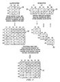
- FIGURE 3 shows an example of a number of confusion matrices that may be combined using multiple level classification.
- Confusion matrix 28 includes elements derived according to a relatively broad classification, such as classification 24a.
- Confusion matrices 30 include elements corresponding to newly received information from sensors 18.
- a final confusion matrix 32 may be generated from confusion matrix 28 and confusion matrices 30.
- Final confusion matrix 32 is constructed recursively, starting with the most basic object categories and progressing through more and more specific classifications through each iteration. To generate a more specific classification, multiple level classifier 14 expands confusion matrix 28 to expanded confusion matrix 28' by dividing each element except for diagonal elements by the factor of expansion. Multiple level classifier 14 arranges confusion matrices 30 in a sparse diagonal matrix 30' as shown. Final confusion matrix 32 is formed by element-wise multiplication between expanded matrix 28' and sparse diagonal block matrix 30'.
- the diagonal elements of final confusion matrix 32 indicate belief state 28 in which object 20 may be assumed to be valid.
- Categorical information may be extracted from belief state 28 of final confusion matrix 32 by summing classes belonging a particular category. For example, the probability of object 20 being a tank in which constituent belief states 26 indicate a 20 percent chance the object is a T72 tank, 10 percent chance it is a M1 tank, and 15 percent chance it is a M109 tank. Therefore, the chance that object 20 is a tank is simply 20 percent plus 10 percent plus 15 percent equal percent.
- computing nodes 12 may transmit the appropriate row from the confusion matrix 30 associated with object 20 at the measurement's position. This row will have dimension 1 ⁇ C, where C is the number of classes in belief state 28. Thus, processing load may be shared among a multiple number of computing nodes 12.
- information processing system 10 may comprise more, fewer, or other elements.
- information processing system 10 described above generates three differing levels of classifications.
- information processing system 10 may generate any type and number of classifications suitable for a particular application.
- "each" refers to each member of a set or each member of a subset of a set.
- FIGURE 4 is a flowchart showing one embodiment of a series of actions that may be performed by the information processing system 10. In act 100, the process is initiated.
- sensors 18 generate records 22 from information corresponding to a particular object 20 of interest.
- Information may be generally broad in context such that object 20 may be unknown. That is, the identity of object 20 may be relatively unknown using information available in any one particular record 22.
- sensors 18 transmit records 22 to one or more computing nodes 12 over network 16.
- information processing system 10 is a distributed computing system having a number of computing nodes 12. Multiple computing nodes 12 may distribute processing load by transmitting records 22 to one another for binding a portion of records 22 generated by sensors 18.
- a computing node 12 recursively binds records 22 in a hierarchal number of classifications according to specificity. That is, computing node 12 binds records 22 with one another to classify records 22 at a first level of specificity. After a specified period of time, computing node 12 binds records 22 with a subsequently received set of records 22 in another classification having a relatively higher level of specificity.
- computing node 12 determines a trajectory of object 20 using records 22 that were received over a specified period of time. In one embodiment, computing node 12 determines the trajectory using a Kalman filter. In another embodiment, computing node 12 determines the trajectory using an information form of the Kalman filter.
- computing node 12 associates records 22 with an existing trajectory.
- computing node 12 associates records 22 with an existing trajectory using a scoring algorithm, such as the Munkres algorithm.
- the Munkres algorithm calculates a Euclidean distance of information in records 22 from an existing trajectory using a covariance factor. Because the covariance factor is normally provided by the Kalman filter, the covariance factor may be used to further distinguish information in records 22.
- Acts 102 through 108 may be repeatedly performed by one or more computing nodes 12 to resolve the trajectory and/or specificity of information in records 22. When operation of information processing system 10 is no longer needed or desired, the process ends in act 110.
- the method may include more, fewer, or other steps.
- the described method classifies and recursively resolves the trajectory of one particular object 20.
- information processing system 10 may add and/or delete multiple objects with each set of records 22 received by the one or more computing nodes 12.
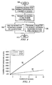
- FIGURE 5 is a graph showing an estimated resource usage of information processing system 10.
- the graph includes several plots 36 and 38 indicating floating point operations (FLOPs) used by information processing system 10 and another information processing system configured in a centralized network.
- Plot 36 indicates a number of floating point operations (FLOPs) that may be executed by each computing node 12 as a function of the quantity of sensors 18 used by an information processing system configured in a centralized network.
- Plot 38 indicates a number of floating point operations (FLOPs) that may be executed by each computing node 12 as a function of the quantity of sensors 18 used in information processing system 10.
- information processing system 10 configured in a distributed network uses approximately one-fourth the number of floating point operations if ten sensors 18 are used. For an information processing system 10 having a relatively large number of sensors 18, therefore, the processing load for each processing node 12 may be reduced.
- FIGURE 6 is a bar chart indicating the number of bytes transmitted between computing nodes 12 over network 16 using information processing system 10 and another information processing system configured in a centralized network. Bars 44 indicate the number of bytes transmitted using an information processing system configured in a centralized network and bars 46 indicate the number of bytes transmitted by information processing system 10. In this particular bar chart, the number of bytes transmitted is calculated as a function of the number of false alarms per record 22. In reality, information derived from sensors 18 are subject to random perturbations due to noise. Thus, partial processing of records 22 in multiple processing nodes 12 may reduce loading on network 16 using a distributed processing architecture. As shown, information processing system 10 may have relatively constant byte transmission levels regardless of the number of false alarms generated by sensors 18. The information processing system configured in a centralized network, however, may increase relative to the number of false alarms generated.
Landscapes
- Engineering & Computer Science (AREA)
- Theoretical Computer Science (AREA)
- Data Mining & Analysis (AREA)
- Computer Vision & Pattern Recognition (AREA)
- Physics & Mathematics (AREA)
- General Physics & Mathematics (AREA)
- Artificial Intelligence (AREA)
- Life Sciences & Earth Sciences (AREA)
- Multimedia (AREA)
- Bioinformatics & Cheminformatics (AREA)
- Bioinformatics & Computational Biology (AREA)
- Evolutionary Biology (AREA)
- Evolutionary Computation (AREA)
- General Engineering & Computer Science (AREA)
- Arrangements For Transmission Of Measured Signals (AREA)
- Radar Systems Or Details Thereof (AREA)
Abstract
Description
- This disclosure generally relates to computing systems, and more particularly, to an information processing system for classifying an object and a method of performing the same.
- Distributed computing systems delegate processing load over a number of constituent computing nodes. Distributed computing systems may provide relatively efficient use of computing resources by distributing processing load of multiple users. Computing nodes of a distributed computing system often communicate with one another through a network, such as the Internet or a wireless network using radio frequency (RF) links.
- It is an object of the present invention to provide for a system and method classifying and/or tracking an object. This object can be achieved by the features as defined in the independent claims. Further enhancements are characterized in the dependent claims.
- According to one embodiment, a computing system includes a computing node coupled to a number of sensors. The sensors are operable to generate records from received information and transmit these records to the computing node. The computing node is operable to bind the plurality of records in a plurality of classifications using a multiple level classifier such that each classification has a differing level of specificity.
- Some embodiments of the disclosure may provide numerous technical advantages. For example, one embodiment of the information processing system may be relatively more immune to noise using the multiple levels of classification provided by multiple level classifier. Sensors may generate information at varying levels of perception. The multiple level classifier may combine useable information having differing levels of perception by recursively classifying this information in multiple classification levels. Noise introduced by sensors may be filtered, therefore, with a greater level of granularity.
- As another example, information processing system may be implemented in a distributed architecture for enhanced robustness against individual sensor failure. That is, the loss of a single sensor in a distributed architecture may not impact the overall performance of the information processing system. While the loss of an important node in a centralized network can drop system efficiency dramatically, the loss of any computing node in a distributed network might reduce the system efficiency only marginally. In addition, the information processing system configured in a distributed architecture may have lighter communication requirements in environments with a relatively large amount of noise.
- Some embodiments may benefit from some, none, or all of these advantages. Other technical advantages may be readily ascertained by one of ordinary skill in the art.
- A more complete understanding of exemplary embodiments of the disclosure will be apparent from the detailed description taken in conjunction with the accompanying drawings in which:
-
FIGURE 1 is a diagram of one embodiment of an information processing system according to the teachings of the present disclosure; -
FIGURE 2 is a diagram showing several classifications that may be generated by the information processing system ofFIGURE 1 ; -
FIGURE 3 shows example confusion matrices that may be generated by the information processing system ofFIGURE 1 ; -
FIGURE 4 is a flowchart showing one embodiment of a series of actions that may be performed by the information processing system ofFIGURE 1 ; -
FIGURE 5 is a chart comparing a resource usage of the information processing system ofFIGURE 1 with another information processing system configured in a centralized network; and -
FIGURE 6 is a bar chart comparing transmitted bytes of the information processing system ofFIGURE 1 with another information processing system configured in a centralized network. - As previously described, network computing systems may distribute processing load to a number of constituent computing nodes coupled together through a network. Distributed computing systems have certain advantages over their centralized counterparts. For example, they may provide parallel processing techniques to ease computational burden, and unlike centralized computing systems, they may not be as prone to catastrophic failure if one particular component ceases to function.
- A network computing system may function as an information processing system. Information processing systems process information from one or more sources. In some cases, sources of information may be relatively disparate in form as well as context. For example, intelligence, surveillance, and reconnaissance (ISR) activities may use information received from a number of differing sensors. These sensors may provide information that is relatively disparate in form and/or context. Correlation of information from various sensors in an information processing system, therefore, may be relatively difficult due to the relatively diverse form and/or context of information provided.
-
FIGURE 1 shows one embodiment of aninformation processing system 10 configured in a distributed network.Information processing system 10 includes a number ofcomputing nodes 12 executing amultiple level classifier 14 that are coupled together through anetwork 16 as shown.Certain computing nodes 12 may have one ormore sensors 18 for gathering information about anobject 20, which may be, for example, a military tank. As will be described in detail below,multiple level classifier 14 may be executed bycomputing nodes 12 to classify information generated bysensors 18 into classifications with varying levels of specificity. -
Sensors 18 generaterecords 22 from the received information and transmit theserecords 22 toother computing nodes 12 in the network.Computing nodes 12 bindrecords 22 in a number ofclassifications 24 according to a level of specificity. From themultiple classifications 24, enhanced information aboutobject 20 may be determined. That is,multiple level classifier 14 may be operable to derive enhanced information from information provided bysensors 18 using a process referred to as data exploitation and mining. Data, in this sense, may generally refer to signals, images, or other relative information that may be associated with priori information or other circumstantial evidences to derive enhanced information. In some embodiments,computing nodes 12 may also determine a trajectory ofobject 20 fromrecords 22 generated over a period of time. - In certain embodiments, binding of
records 22 inmultiple classifications 24 may be useful when the identity of the object is generally unknown. That is, information fromnumerous sensors 18 providing disparate information may be combined in a hierarchal manner to identify theunknown object 20. Certain embodiments ofinformation processing system 10, therefore, may derive useful information from a relatively large amount of data provided bysensors 18 that generate information at varying levels of perception. -
Computing nodes 12 may be any suitable type of computing system that execute instructions stored in a memory. Examples of computing systems may include personal computers, personal digital assistants (PDAs), laptop computers, application-specific computing units/systems, and/or mainframe computers.Network 16 in whichcomputing nodes 12 communicate may be any suitable network, such as such as a local area network (LAN), a metropolitan area network (MAN), or a wide area network (WAN). In one embodiment,network 16 is the Internet. In another embodiment,network 16 is a wireless network in whichcomputing nodes 12 communicate with one another using radio frequency links. -
Information processing system 10 may receive information from any type ofsensor 12 in the network. For example,sensors 12 may include one or more of a signal intelligence (SIGINT) sensor, such as tactical electronic reconnaissance processing and evaluation system (TERPES) sensors, team portable collection system (TPCS) sensors, radio reconnaissance equipment program (RREP) sensors, tactical control and analysis center (TCAC) sensors, mobile electronic warfare support system (MEWSS) sensors, and/or communication emitter sensing attacking system (CESAS) sensors.Sensors 12 may also include imagery intelligence (IMINT) sensors, such as manpack secondary imagery dissemination system (MSIDS) sensors, tactical exploitation group (TEG) sensors, and/or firescout unmanned aircraft system (UAS) sensors. As other examples,sensors 12 may include measurement and signal intelligence (MASINT) sensors, such as tactical remote sensor system (TRSS) sensors, expeditionary tactical area surveillance system (ETASS) sensors, or critical area protection system (CAPS) sensors. Sensors may also include human intelligence (HUMANT) sensors, such as counter intelligence and HUMANT equipment program (CIHEP) sensors. - In one embodiment, binding of
records 22 inmultiple classifications 24 may be performed bymultiple computing nodes 12. In this manner, processing load may be distributed over a number ofcomputing nodes 12.Individual processing nodes 12 may bind a portion ofrecords 22 and forward these processedrecords 22 to anothercomputing node 12 for processing withother records 22. Classification ofrecords 22 byinformation processing system 10 will be described in detail below. - In one embodiment,
information processing system 10 determines a trajectory ofobject 20 fromrecords 22 received over a specified period of time.Sensors 18 may continually receive information aboutobject 20 over time. This information may be used to generaterecords 22 at periodic or irregular time intervals.Information processing system 10 may userecords 22 generated at differing time periods to determine a trajectory ofobject 20. - The trajectory of a linear system may be governed by the following equations:


- xt is the state of one of the targets at time t;
- Φ is the state transition matrix;
- Q is the process noise; and
- N(m, Σ) denotes the multivariate normal distribution with mean vector m and covariance matrix Σ.
- If the target is observable at time t by sensor j (which depends on the state of the track and the action selected for the sensor), then a kinematic observation (zt,j) will be generated according to:


- Ht,j is the measurement transfer matrix;
- Rt,j is a measure of the accuracy of the measurement; and
- Z t to be the set of all the kinematic observations of a track at time t.
- xt may be generally unobservable. In one embodiment,
information processing system 10 determines a trajectory ofobject 20 using a Kalman filter. The Kalman filter recursively estimates the trajectory ofobject 20 with receipt of eachnew record 22. The Kalman filter maintains a least-squares estimate x(t|t) = E[xt | Z1, ..., Zt] and a covariance matrix P(t|t) - E[x(t|t) xT(t|t) | Z1, ..., Zt] of the error. This is recursively maintained through the following sets of equations:


- x̂1 is the current track estimate; and
- Pt is the covariance associated with that estimate.
- In one embodiment, the Kalman filter may be an information form of the Kalman filter. The information form of the Kalman filter is mathematically identical to the basic Kalman filter, but the equations have been manipulated to reduce the complexity of updating the kinematic state with a new measurement. The steps of the information form of the Kalman filter are shown in the following formulae:


- For the information form of the Kalman filter, the ij,t and I j,t vectors are known as the information vectors.
Individual computing nodes 12 may receiverecords 22 fromother computing nodes 12, bind the receivedrecords 22 withother records 22, and forward the result as information vectors (ij,t and Ij,t ) toother computing nodes 12 in the distributed network. Thus, a number ofcomputing nodes 12 share processing load for executing the information form of the Kalman filter. - Information included in
records 22 in some instances, may not be associated with any oneparticular object 20 during creation. That is,sensors 18 do not generally impart information about the type of object or its trajectory. To determine a trajectory ofobject 20, therefore, information may be associated with an existing trajectory. In one embodiment, information may be associated with an existing trajectory using a scoring algorithm. One particular suitable scoring algorithm is a Munkres algorithm. The Munkres algorithm may be applied to information included in receivedrecords 22. - For example, assume there are M workers and N tasks, and each combination MN has an associated cost CMN. The Munkres algorithm determines which workers should perform which tasks to minimize the total cost. For the present case, the workers are existing trajectories and the tasks are newly received information in
records 22. The cost CMN may be defined by the Mahalanobis distance, given by:
- The Mahalanobis distance may be generally similar to the Euclidean distance; the difference being the inclusion of the covariance factor Σ. The covariance factor used is that of the measurement itself. This means that if two measurements are equidistant from an existing trajectory, but each measurement has a different covariance factor Σ, the measurement with the smallest covariance factor will be associated with the trajectory. Association can be performed by either computing
node 12 ininformation processing system 10. - Distributed classification of
records 22 may be accomplished in any suitable manner. In one embodiment, distributed classification is accomplished using a Bayesian reasoning classifier. The Bayesian reasoning classifier may be implemented using confusion matrices. The klth element of Θtj gives the probability at time t that sensor j reports the track as type k when it istype 1. This matrix may be generated by one or moreindividual computing nodes 12. The results may be communicated withother computing nodes 12 as a number labeling the appropriate row of the matrix to be used in the belief state. - The uncertainty may be modeled as a multinomial distribution; the kth element of the belief state b(t) is the belief (i.e. probability) at time t that the trajectory is type k, given all the observations that have come up to (and including) time t. If the trajectory is observable at time t by sensor j, then an identification observation (otj ) will be produced. The belief state can then be updated according to:

- Ot is the set of all the identification observations of a track at time t.
- The process used to compute the elements of the confusion matrix are calculated. First, the probability that an object will be identified as class k may be determined, given that it is class k. The probability of correct identification P(k|k) is given by Johnson's criteria:


- N is the number of resolution elements on the target when the measurement is taken; and
- N50 specifies the number of resels required for a 50% chance of associating the object with the correct type.
- N50 depends on the perception level of interest. A table of values for differing levels of perception are provided in Table 1. It is assumed that all incorrect identifications are equiprobable. Therefore, the probability that class k is identified as being
class 1, assuming thatk # 1, is:
- C is the number of possible classes.
-
FIGURE 2 is diagram showing one embodiment of a multiple level classification structure that may be generated byinformation processing system 10. In this particular embodiment, objects 20 (FIGURE 1 ) may be classified in three classifications having differing levels of specificity. Each object 20 (FIGURE 1 ) may be associated with a belief state 28 (FIGURE 3 ).Classification 24a is a generally broad classification in which objects 20 may be classified as friendly, neutral, or hostile.Classification 24b includes criteria that is relatively more specific thanclassification 24a. Namely, objects 20 may be classified inclassification 24b as a friendly tank, a friendly humvee, a neutral car, a hostile tank, or a hostile car.Classification 24c has relatively greater specificity thanclassification 24b in that objects 20 may be identified according to their type. - In practice, some objects may be misclassified at varying levels of classification. For example, a tank is more likely to be misclassified as a different type of tank rather than a type of car. Therefore, a single level of classification model may not reflect this difference. Certain embodiments may provide relatively more comprehensive classification of objects than single level classifiers.
Multiple level classifier 14 provides varying levels of specificity of information aboutobject 20. That is,multiple level classifier 14 may incorporate a hierarchical classification structure to provide enhanced contextual information aboutobject 20. - The form of the
belief state 28 for multiple level classification is one-dimensional. First, confusion matrices for each category and sub-category are constructed, which assumes that all incorrect classifications are equiprobable.Multiple level classifier 14 assumes that each record 22 includes information associated with thesame object 20 as previously received. Let us call the constituent confusion matrices Θ1, ..., Θc and the final confusion matrix at each level Y L , where c is the number of subcategories beneath the current category and L is the perception level. The recursive algorithm used to determine the confusion matrix for each level of classification is:


- Equation (17) yields the final confusion matrix for that particular level. The ⊗ symbol is the Kronecker product, and is used to repeat the elements in the parent matrix Nc times, where Nc is the size of the confusion matrix Θ c . l m represents the mth category of
perception level 1. After the highest perception level confusion matrix has been constructed, the lower levels are expanded to have the same size using equation (17). After the confusion matrices are constructed, thebelief state 28 is updated using equation (11). The confusion matrix may be associated with the perception level of the observations returned fromsensors 18. This process is shown using an example described below, which constructs a confusion matrix from bothclassification 24 and recognition probabilities. -
FIGURE 3 shows an example of a number of confusion matrices that may be combined using multiple level classification.Confusion matrix 28 includes elements derived according to a relatively broad classification, such asclassification 24a.Confusion matrices 30 include elements corresponding to newly received information fromsensors 18. Afinal confusion matrix 32 may be generated fromconfusion matrix 28 andconfusion matrices 30. -
Final confusion matrix 32 is constructed recursively, starting with the most basic object categories and progressing through more and more specific classifications through each iteration. To generate a more specific classification,multiple level classifier 14 expandsconfusion matrix 28 to expanded confusion matrix 28' by dividing each element except for diagonal elements by the factor of expansion.Multiple level classifier 14 arrangesconfusion matrices 30 in a sparse diagonal matrix 30' as shown.Final confusion matrix 32 is formed by element-wise multiplication between expanded matrix 28' and sparse diagonal block matrix 30'. - The diagonal elements of
final confusion matrix 32 indicatebelief state 28 in which object 20 may be assumed to be valid. Categorical information may be extracted frombelief state 28 offinal confusion matrix 32 by summing classes belonging a particular category. For example, the probability ofobject 20 being a tank in which constituent belief states 26 indicate a 20 percent chance the object is a T72 tank, 10 percent chance it is a M1 tank, and 15 percent chance it is a M109 tank. Therefore, the chance that object 20 is a tank is simply 20 percent plus 10 percent plus 15 percent equal percent. - For a distributed network,
computing nodes 12 may transmit the appropriate row from theconfusion matrix 30 associated withobject 20 at the measurement's position. This row will havedimension 1×C, where C is the number of classes inbelief state 28. Thus, processing load may be shared among a multiple number ofcomputing nodes 12. - Modifications, additions, or omissions may be made to
information processing system 10 without departing from the scope of the disclosure. Moreover,information processing system 10 may comprise more, fewer, or other elements. For example,information processing system 10 described above generates three differing levels of classifications. In other embodiments,information processing system 10 may generate any type and number of classifications suitable for a particular application. As used in this document, "each" refers to each member of a set or each member of a subset of a set. -
FIGURE 4 is a flowchart showing one embodiment of a series of actions that may be performed by theinformation processing system 10. Inact 100, the process is initiated. - In act 102,
sensors 18 generaterecords 22 from information corresponding to aparticular object 20 of interest. Information may be generally broad in context such thatobject 20 may be unknown. That is, the identity ofobject 20 may be relatively unknown using information available in any oneparticular record 22. - In
act 104,sensors 18 transmitrecords 22 to one ormore computing nodes 12 overnetwork 16. In one embodiment,information processing system 10 is a distributed computing system having a number ofcomputing nodes 12.Multiple computing nodes 12 may distribute processing load by transmittingrecords 22 to one another for binding a portion ofrecords 22 generated bysensors 18. - In
act 106, acomputing node 12 recursively bindsrecords 22 in a hierarchal number of classifications according to specificity. That is, computingnode 12 bindsrecords 22 with one another to classifyrecords 22 at a first level of specificity. After a specified period of time,computing node 12 bindsrecords 22 with a subsequently received set ofrecords 22 in another classification having a relatively higher level of specificity. - In
act 108, computingnode 12 determines a trajectory ofobject 20 usingrecords 22 that were received over a specified period of time. In one embodiment, computingnode 12 determines the trajectory using a Kalman filter. In another embodiment, computingnode 12 determines the trajectory using an information form of the Kalman filter. - To determine the trajectory, computing
node 12associates records 22 with an existing trajectory. In one embodiment, computingnode 12associates records 22 with an existing trajectory using a scoring algorithm, such as the Munkres algorithm. The Munkres algorithm calculates a Euclidean distance of information inrecords 22 from an existing trajectory using a covariance factor. Because the covariance factor is normally provided by the Kalman filter, the covariance factor may be used to further distinguish information inrecords 22. - Acts 102 through 108 may be repeatedly performed by one or
more computing nodes 12 to resolve the trajectory and/or specificity of information inrecords 22. When operation ofinformation processing system 10 is no longer needed or desired, the process ends inact 110. - Modifications, additions, or omissions may be made to the method without departing from the scope of the disclosure. The method may include more, fewer, or other steps. For example, the described method classifies and recursively resolves the trajectory of one
particular object 20. In other embodiments,information processing system 10 may add and/or delete multiple objects with each set ofrecords 22 received by the one ormore computing nodes 12. -
FIGURE 5 is a graph showing an estimated resource usage ofinformation processing system 10. The graph includesseveral plots information processing system 10 and another information processing system configured in a centralized network.Plot 36 indicates a number of floating point operations (FLOPs) that may be executed by each computingnode 12 as a function of the quantity ofsensors 18 used by an information processing system configured in a centralized network.Plot 38 indicates a number of floating point operations (FLOPs) that may be executed by each computingnode 12 as a function of the quantity ofsensors 18 used ininformation processing system 10. As shown,information processing system 10 configured in a distributed network uses approximately one-fourth the number of floating point operations if tensensors 18 are used. For aninformation processing system 10 having a relatively large number ofsensors 18, therefore, the processing load for eachprocessing node 12 may be reduced. -
FIGURE 6 is a bar chart indicating the number of bytes transmitted betweencomputing nodes 12 overnetwork 16 usinginformation processing system 10 and another information processing system configured in a centralized network.Bars 44 indicate the number of bytes transmitted using an information processing system configured in a centralized network and bars 46 indicate the number of bytes transmitted byinformation processing system 10. In this particular bar chart, the number of bytes transmitted is calculated as a function of the number of false alarms perrecord 22. In reality, information derived fromsensors 18 are subject to random perturbations due to noise. Thus, partial processing ofrecords 22 inmultiple processing nodes 12 may reduce loading onnetwork 16 using a distributed processing architecture. As shown,information processing system 10 may have relatively constant byte transmission levels regardless of the number of false alarms generated bysensors 18. The information processing system configured in a centralized network, however, may increase relative to the number of false alarms generated. - Although the present disclosure has been described in several embodiments, a myriad of changes, variations, alterations, transformations, and modifications may be suggested to one skilled in the art, and it is intended that the present disclosure encompass such changes, variations, alterations, transformations, and modifications as falling within the spirit and scope of the appended claims.
| 1.5 resels (0.75 cycles) per critical dimension | 50 |
| 3 resels (1.5 cycles) per critical dimension | 50 |
| 6 resels (3 cycles) per critical dimension | 50 |
| 12 resels (6 cycles) per critical dimension | 50% identification probability |
Claims (17)
Applications Claiming Priority (2)
| Application Number | Priority Date | Filing Date | Title |
|---|---|---|---|
| US88918407P | 2007-02-09 | 2007-02-09 | |
| US12/027,588 US8010658B2 (en) | 2007-02-09 | 2008-02-07 | Information processing system for classifying and/or tracking an object |
Publications (2)
| Publication Number | Publication Date |
|---|---|
| EP1956520A2 true EP1956520A2 (en) | 2008-08-13 |
| EP1956520A3 EP1956520A3 (en) | 2009-07-01 |
Family
ID=39415256
Family Applications (1)
| Application Number | Title | Priority Date | Filing Date |
|---|---|---|---|
| EP08002402A Withdrawn EP1956520A3 (en) | 2007-02-09 | 2008-02-08 | Information processing system for classifying and/or tracking an object |
Country Status (2)
| Country | Link |
|---|---|
| US (1) | US8010658B2 (en) |
| EP (1) | EP1956520A3 (en) |
Families Citing this family (15)
| Publication number | Priority date | Publication date | Assignee | Title |
|---|---|---|---|---|
| US20100138919A1 (en) * | 2006-11-03 | 2010-06-03 | Tao Peng | System and process for detecting anomalous network traffic |
| AU2007254600B2 (en) * | 2007-12-20 | 2011-04-14 | Canon Kabushiki Kaisha | Collaborative tracking |
| US8199643B2 (en) * | 2009-01-20 | 2012-06-12 | Raytheon Company | Optimization strategies for resource management and course of action analysis |
| US9020259B2 (en) | 2009-07-20 | 2015-04-28 | Thomson Licensing | Method for detecting and adapting video processing for far-view scenes in sports video |
| US8234689B2 (en) * | 2009-07-21 | 2012-07-31 | Bae Systems Information And Electronic Systems Integration Inc. | System and method for generating target area information of a battlefield using information acquired from multiple classification levels |
| US8634982B2 (en) * | 2009-08-19 | 2014-01-21 | Raytheon Company | System and method for resource allocation and management |
| US8396730B2 (en) * | 2011-02-14 | 2013-03-12 | Raytheon Company | System and method for resource allocation and management |
| PL398136A1 (en) | 2012-02-17 | 2013-08-19 | Binartech Spólka Jawna Aksamit | Method for detecting the portable device context and a mobile device with the context detection module |
| US9836989B2 (en) * | 2012-06-05 | 2017-12-05 | Rockwell Collins, Inc. | Training data management method and related system |
| US9679252B2 (en) | 2013-03-15 | 2017-06-13 | Qualcomm Incorporated | Application-controlled granularity for power-efficient classification |
| US10102259B2 (en) | 2014-03-31 | 2018-10-16 | International Business Machines Corporation | Track reconciliation from multiple data sources |
| WO2015154017A1 (en) * | 2014-04-03 | 2015-10-08 | Evolvtechnologies, Inc. | Feature extraction for radar |
| SE1650719A1 (en) * | 2016-05-25 | 2017-11-26 | Scania Cv Ab | Method for decentralised sensor fusion in a vehicle and sensor fusion system |
| US11320243B2 (en) * | 2018-03-28 | 2022-05-03 | Bae Systems Information And Electronic Systems Integration Inc. | Combat identification server correlation report |
| US20230092627A1 (en) * | 2021-09-21 | 2023-03-23 | International Business Machines Corporation | Distributed sensing and classification |
Family Cites Families (8)
| Publication number | Priority date | Publication date | Assignee | Title |
|---|---|---|---|---|
| US5842156A (en) * | 1996-11-12 | 1998-11-24 | The United States Of America As Represented By The Secretary Of The Air Force | Multirate multiresolution target tracking |
| US6014447A (en) * | 1997-03-20 | 2000-01-11 | Raytheon Company | Passive vehicle classification using low frequency electro-magnetic emanations |
| US6269324B1 (en) * | 1998-10-19 | 2001-07-31 | Raytheon Company | Magnetic object tracking based on direct observation of magnetic sensor measurements |
| US6393137B1 (en) * | 1999-06-17 | 2002-05-21 | Raytheon Company | Multi-resolution object classification method employing kinematic features and system therefor |
| US6829568B2 (en) | 2002-04-26 | 2004-12-07 | Simon Justin Julier | Method and apparatus for fusing signals with partially known independent error components |
| US6882959B2 (en) | 2003-05-02 | 2005-04-19 | Microsoft Corporation | System and process for tracking an object state using a particle filter sensor fusion technique |
| US7005981B1 (en) | 2003-05-27 | 2006-02-28 | The United States Of America As Represented By The Secretary Of The Army | Method and apparatus for the extraction and compression of surveillance information to facilitate high performance data fusion in distributed sensor systems |
| EP1596334A1 (en) | 2004-05-13 | 2005-11-16 | Technologiestichting STW | A hybrid graphical model for on-line multicamera tracking |
-
2008
- 2008-02-07 US US12/027,588 patent/US8010658B2/en active Active
- 2008-02-08 EP EP08002402A patent/EP1956520A3/en not_active Withdrawn
Non-Patent Citations (4)
| Title |
|---|
| OXENHAM ET AL: "Fusion of disparate identity estimates for shared situation awareness in a network-centric environment", INFORMATION FUSION, ELSEVIER, US, vol. 7, no. 4, 16 November 2006 (2006-11-16), pages 395 - 417, XP005770618, ISSN: 1566-2535, DOI: 10.1016/J.INFFUS.2005.09.003 * |
| OXENHAM M. ET AL.: "Fusion of disparate identity estimates for shared situation awareness in a network-centric environment", INFORMATION FUSION, vol. 7, 2006, pages 395 - 417 |
| SHI, W. ET AL.: "Multi-Modal Netted Sensor Fence for Homeland Security", PROC. SPIE, vol. 5796, 2005, pages 416 - 427 |
| SPIE, PO BOX 10 BELLINGHAM WA 98227-0010 USA, XP040204265 * |
Also Published As
| Publication number | Publication date |
|---|---|
| US20080235318A1 (en) | 2008-09-25 |
| US8010658B2 (en) | 2011-08-30 |
| EP1956520A3 (en) | 2009-07-01 |
Similar Documents
| Publication | Publication Date | Title |
|---|---|---|
| US8010658B2 (en) | Information processing system for classifying and/or tracking an object | |
| Ruff et al. | Deep semi-supervised anomaly detection | |
| Shahzad et al. | Every bit counts: Fast and scalable RFID estimation | |
| Mahler | Advances in statistical multisource-multitarget information fusion | |
| Vo et al. | An efficient implementation of the generalized labeled multi-Bernoulli filter | |
| Vo et al. | Labeled random finite sets and the Bayes multi-target tracking filter | |
| US20190331485A1 (en) | Movement line information generation system, movement line information generation method and movement line information generation program | |
| US7478071B2 (en) | Method and apparatus for determining and assessing information to be collected based on information-theoretic measures | |
| US7941292B2 (en) | Associating observations in a multi-sensor system using an adaptive gate value | |
| WO2012098853A1 (en) | Flow line detection process data distribution system, flow line detection process data distribution method, and program | |
| Mei et al. | Bayesian optimization through gaussian cox process models for spatio-temporal data | |
| EP3660750B1 (en) | Method and system for classification of data | |
| Enoch et al. | A Comparative Performance Study of Support Vector Machine, KNN, and Ensemble Classifiers on through-wall human detection Dataset | |
| Singha et al. | Securing contrastive mmwave-based human activity recognition against adversarial label flipping | |
| Barbieri et al. | Compressed Bayesian federated learning for reliable passive radio sensing in industrial IoT | |
| Chung | On probabilistic search decisions under searcher motion constraints | |
| Banerjee et al. | Data lifecycle management in evolving input distributions for learning-based aerospace applications | |
| Foil et al. | Probabilistic surface classification for rover instrument targeting | |
| Bibi et al. | A Bayesian-optimized 1D CNN-based outlier detection approach for wireless sensor networks | |
| Nguyen et al. | Tag cardinality estimation using expectation-maximization in ALOHA-based RFID systems with capture effect and detection error | |
| Shenoy et al. | Anamoly detection in wireless sensor networks | |
| Wettergren et al. | Discrete search allocation with object uncertainty | |
| Adla et al. | Multi sensor data fusion, methods and problems | |
| US20070143072A1 (en) | RFID systems and methods for probabalistic location determination | |
| Glinton et al. | A markov random field model of context for high-level information fusion |
Legal Events
| Date | Code | Title | Description |
|---|---|---|---|
| PUAI | Public reference made under article 153(3) epc to a published international application that has entered the european phase |
Free format text: ORIGINAL CODE: 0009012 |
|
| 17P | Request for examination filed |
Effective date: 20080208 |
|
| AK | Designated contracting states |
Kind code of ref document: A2 Designated state(s): AT BE BG CH CY CZ DE DK EE ES FI FR GB GR HR HU IE IS IT LI LT LU LV MC MT NL NO PL PT RO SE SI SK TR |
|
| AX | Request for extension of the european patent |
Extension state: AL BA MK RS |
|
| PUAL | Search report despatched |
Free format text: ORIGINAL CODE: 0009013 |
|
| AK | Designated contracting states |
Kind code of ref document: A3 Designated state(s): AT BE BG CH CY CZ DE DK EE ES FI FR GB GR HR HU IE IS IT LI LT LU LV MC MT NL NO PL PT RO SE SI SK TR |
|
| AX | Request for extension of the european patent |
Extension state: AL BA MK RS |
|
| RIC1 | Information provided on ipc code assigned before grant |
Ipc: G06T 7/20 20060101ALI20090526BHEP Ipc: G06K 9/62 20060101AFI20090526BHEP |
|
| 17Q | First examination report despatched |
Effective date: 20090807 |
|
| AKX | Designation fees paid |
Designated state(s): AT BE BG CH CY CZ DE DK EE ES FI FR GB GR HR HU IE IS IT LI LT LU LV MC MT NL NO PL PT RO SE SI SK TR |
|
| GRAP | Despatch of communication of intention to grant a patent |
Free format text: ORIGINAL CODE: EPIDOSNIGR1 |
|
| STAA | Information on the status of an ep patent application or granted ep patent |
Free format text: STATUS: THE APPLICATION IS DEEMED TO BE WITHDRAWN |
|
| 18D | Application deemed to be withdrawn |
Effective date: 20120906 |