EP1956448A1 - Vehicle control system and method using control allocation and phase compensation - Google Patents
Vehicle control system and method using control allocation and phase compensation Download PDFInfo
- Publication number
- EP1956448A1 EP1956448A1 EP07102162A EP07102162A EP1956448A1 EP 1956448 A1 EP1956448 A1 EP 1956448A1 EP 07102162 A EP07102162 A EP 07102162A EP 07102162 A EP07102162 A EP 07102162A EP 1956448 A1 EP1956448 A1 EP 1956448A1
- Authority
- EP
- European Patent Office
- Prior art keywords
- control
- signal vector
- vehicle
- unit
- behaviour
- Prior art date
- Legal status (The legal status is an assumption and is not a legal conclusion. Google has not performed a legal analysis and makes no representation as to the accuracy of the status listed.)
- Granted
Links
- 238000000034 method Methods 0.000 title claims abstract description 61
- 239000011159 matrix material Substances 0.000 claims abstract description 51
- 238000001914 filtration Methods 0.000 claims description 13
- 230000003321 amplification Effects 0.000 claims description 11
- 238000003199 nucleic acid amplification method Methods 0.000 claims description 11
- 238000005457 optimization Methods 0.000 claims description 5
- 230000000694 effects Effects 0.000 claims description 4
- 238000012546 transfer Methods 0.000 claims description 3
- 238000010586 diagram Methods 0.000 description 9
- RZVHIXYEVGDQDX-UHFFFAOYSA-N 9,10-anthraquinone Chemical compound C1=CC=C2C(=O)C3=CC=CC=C3C(=O)C2=C1 RZVHIXYEVGDQDX-UHFFFAOYSA-N 0.000 description 5
- 230000008901 benefit Effects 0.000 description 5
- 238000013461 design Methods 0.000 description 5
- 238000005516 engineering process Methods 0.000 description 5
- 230000001133 acceleration Effects 0.000 description 4
- 230000010355 oscillation Effects 0.000 description 4
- 230000001276 controlling effect Effects 0.000 description 3
- 230000001419 dependent effect Effects 0.000 description 3
- 230000008859 change Effects 0.000 description 2
- 230000008878 coupling Effects 0.000 description 2
- 238000010168 coupling process Methods 0.000 description 2
- 238000005859 coupling reaction Methods 0.000 description 2
- 230000001934 delay Effects 0.000 description 2
- 230000009467 reduction Effects 0.000 description 2
- 238000004088 simulation Methods 0.000 description 2
- 230000003044 adaptive effect Effects 0.000 description 1
- 230000003467 diminishing effect Effects 0.000 description 1
- 238000005259 measurement Methods 0.000 description 1
- 238000012545 processing Methods 0.000 description 1
- 230000001105 regulatory effect Effects 0.000 description 1
- 230000004044 response Effects 0.000 description 1
- 238000007493 shaping process Methods 0.000 description 1
- 230000019491 signal transduction Effects 0.000 description 1
- 230000026676 system process Effects 0.000 description 1
Images

Classifications
-
- G—PHYSICS
- G05—CONTROLLING; REGULATING
- G05B—CONTROL OR REGULATING SYSTEMS IN GENERAL; FUNCTIONAL ELEMENTS OF SUCH SYSTEMS; MONITORING OR TESTING ARRANGEMENTS FOR SUCH SYSTEMS OR ELEMENTS
- G05B13/00—Adaptive control systems, i.e. systems automatically adjusting themselves to have a performance which is optimum according to some preassigned criterion
- G05B13/02—Adaptive control systems, i.e. systems automatically adjusting themselves to have a performance which is optimum according to some preassigned criterion electric
- G05B13/0205—Adaptive control systems, i.e. systems automatically adjusting themselves to have a performance which is optimum according to some preassigned criterion electric not using a model or a simulator of the controlled system
- G05B13/021—Adaptive control systems, i.e. systems automatically adjusting themselves to have a performance which is optimum according to some preassigned criterion electric not using a model or a simulator of the controlled system in which a variable is automatically adjusted to optimise the performance
-
- G—PHYSICS
- G05—CONTROLLING; REGULATING
- G05B—CONTROL OR REGULATING SYSTEMS IN GENERAL; FUNCTIONAL ELEMENTS OF SUCH SYSTEMS; MONITORING OR TESTING ARRANGEMENTS FOR SUCH SYSTEMS OR ELEMENTS
- G05B13/00—Adaptive control systems, i.e. systems automatically adjusting themselves to have a performance which is optimum according to some preassigned criterion
- G05B13/02—Adaptive control systems, i.e. systems automatically adjusting themselves to have a performance which is optimum according to some preassigned criterion electric
- G05B13/0205—Adaptive control systems, i.e. systems automatically adjusting themselves to have a performance which is optimum according to some preassigned criterion electric not using a model or a simulator of the controlled system
- G05B13/024—Adaptive control systems, i.e. systems automatically adjusting themselves to have a performance which is optimum according to some preassigned criterion electric not using a model or a simulator of the controlled system in which a parameter or coefficient is automatically adjusted to optimise the performance
-
- B—PERFORMING OPERATIONS; TRANSPORTING
- B60—VEHICLES IN GENERAL
- B60K—ARRANGEMENT OR MOUNTING OF PROPULSION UNITS OR OF TRANSMISSIONS IN VEHICLES; ARRANGEMENT OR MOUNTING OF PLURAL DIVERSE PRIME-MOVERS IN VEHICLES; AUXILIARY DRIVES FOR VEHICLES; INSTRUMENTATION OR DASHBOARDS FOR VEHICLES; ARRANGEMENTS IN CONNECTION WITH COOLING, AIR INTAKE, GAS EXHAUST OR FUEL SUPPLY OF PROPULSION UNITS IN VEHICLES
- B60K31/00—Vehicle fittings, acting on a single sub-unit only, for automatically controlling vehicle speed, i.e. preventing speed from exceeding an arbitrarily established velocity or maintaining speed at a particular velocity, as selected by the vehicle operator
-
- G—PHYSICS
- G05—CONTROLLING; REGULATING
- G05B—CONTROL OR REGULATING SYSTEMS IN GENERAL; FUNCTIONAL ELEMENTS OF SUCH SYSTEMS; MONITORING OR TESTING ARRANGEMENTS FOR SUCH SYSTEMS OR ELEMENTS
- G05B13/00—Adaptive control systems, i.e. systems automatically adjusting themselves to have a performance which is optimum according to some preassigned criterion
- G05B13/02—Adaptive control systems, i.e. systems automatically adjusting themselves to have a performance which is optimum according to some preassigned criterion electric
-
- G—PHYSICS
- G05—CONTROLLING; REGULATING
- G05B—CONTROL OR REGULATING SYSTEMS IN GENERAL; FUNCTIONAL ELEMENTS OF SUCH SYSTEMS; MONITORING OR TESTING ARRANGEMENTS FOR SUCH SYSTEMS OR ELEMENTS
- G05B13/00—Adaptive control systems, i.e. systems automatically adjusting themselves to have a performance which is optimum according to some preassigned criterion
- G05B13/02—Adaptive control systems, i.e. systems automatically adjusting themselves to have a performance which is optimum according to some preassigned criterion electric
- G05B13/04—Adaptive control systems, i.e. systems automatically adjusting themselves to have a performance which is optimum according to some preassigned criterion electric involving the use of models or simulators
- G05B13/041—Adaptive control systems, i.e. systems automatically adjusting themselves to have a performance which is optimum according to some preassigned criterion electric involving the use of models or simulators in which a variable is automatically adjusted to optimise the performance
Definitions
- the present invention relates to the field of vehicle control.
- it relates to methods and apparatus for improving performance and stability in a control system where the time derivative of an output from a subsystem is limited, resulting in that an input cannot be fulfilled.
- More particularly it relates to such methods and apparatus for improving control systems provided with some kind of control allocation.
- a control system of a vehicle can be viewed upon as a system performing two subsequent separate steps; a first step comprising calculating a control demand based on operator commands and feedback signals and taking into consideration requirements on stability and performance; and a second step comprising calculating and distributing actuator signals to the available actuators, based on the control demand, such that said control demand will be realised.
- a control demand based on operator commands and feedback signals and taking into consideration requirements on stability and performance
- a second step comprising calculating and distributing actuator signals to the available actuators, based on the control demand, such that said control demand will be realised.
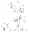
- Figure 1 shows a block diagram illustrating signal pathways in a prior art flight control system design based on such a division into two separate steps.
- feedback couplings may be constructed using any suitable design method such as e.g. PID (Proportional-Integrating-Derivating Control), linear quadratic minimization (LQ), exact linearization (NDI), adaptive methods etc.).
- PID Proportional-Integrating-Derivating Control
- LQ linear quadratic minimization
- NDI exact linearization
- adaptive methods etc.
- the design of software/hardware realising the second step can then be performed without having to consider the actual control laws used.
- the distribution of the control demand is performed by distributing to the available actuators control signals that, when having had their effect on said available actuators, fulfils said control demand on the vehicle.
- This can be achieved by a variety of available methods. Either a fixed (non varying) function, in the linear case a matrix, can be used. In this case the distribution will not be able to adapt to varying effectiveness of the different actuators throughout the envelop of the controlled system. Methods are also available which adapt to the effectiveness of the actuators (control surfaces in aircraft case) and also redistributes the required control if any of the actuators should fail or reach its limitation in position or velocity. These methods usually optimize the actuator performance using the given effectiveness of each actuator, under the given constraints, using some norm (2norm, 1norm or infinity norm).
- a control allocation unit 115 takes said control demand and allocates and distributes actuator signal to available actuators of a vehicle 120. During this allocation and distribution, the control allocation unit 115 considers each actuator's ability to create a certain type of control effect, and modifies the distribution accordingly.
- Such an allocation and distribution makes it possible to handle, independent of system total performance, varying actuator performance, e.g. rudder efficiency, but also actuator position and speed limitations, and also faults in actuators.
- Such faults may include loss, i.e., control surface moves freely, and locking i.e., control surface gets stuck in an arbitrary position.
- Prior art control allocation systems have a tendency to build up an undesired phase loss, when said control allocation systems together with available actuators no longer are able to fulfil current control demand.
- Non-considered phase loss in a regulatory system is highly undesired.
- the operator With an operator in the control loop, the operator may experience a feeling of being disconnected from the system. Using aircraft design vocabulary this is called "Pilot In the Loop Oscillations" and they are feared by both pilots and designers.
- WO 99/09461 to Buck discloses a method and an apparatus for phase compensation in a vehicle control system.
- the document describes how a single control surface actuation rate limiter is combined with phase advancing technology to handle phase loss during actuation rate limiting.
- this solution takes care of one actuator at a time.
- a method and an apparatus for performing phase compensation in a system with multiple actuators where control requirements can be redistributed within a group of actuators.
- the present invention in its most general form relates to a control system for receiving k input signals, which may be represented by an input vector u, and for providing m output signals, which may be represented by an output vector x.
- the system provides the m output signals based on k modified input signals u', related to said k input signals, the m output signals being suitable for feeding m actuators.
- the control system is further provided with means for computing said m output signals such that when said m output signals are effected by said m actuators, the actuators give rise to changes in vehicle attitude status, said status will comply with a control demand expressed e.g., as a demanded attitude status described by the k input signals when this is within the performance limits of the actuators, and to comply with them to a lesser extent, keeping the vehicle controllable, when the k input signals describe a demanded attitude status outside the performance limits of the actuators.
- a control demand expressed e.g., as a demanded attitude status described by the k input signals when this is within the performance limits of the actuators, and to comply with them to a lesser extent, keeping the vehicle controllable, when the k input signals describe a demanded attitude status outside the performance limits of the actuators.
- Means are also provided for forming an estimated motion behaviour y', e.g., an estimated attitude state that comprises k estimated attitude signals. Means are also provided for forming k error signals e 1 ..e k , represented by error vector ⁇ , as the difference between k modified input signals u' and said k estimated motion behavior signals y' 1 ..y' k . Means are also provided for amplifying and phase compensating said k error signals e forming k modified error signals d 1 ..d k . represented by modified error vector d ( ⁇ ). Means are further provided for feeding back said modified error signals d 1 ..d k by forming the difference u' between the k input signals u 1 ..u k and said modified error signals d 1 ..d k .
- the estimated motion behavior y' calculated from actuator commands x may not be the same as the one demanded by input signals u.
- the time derivative of x 1 to x m limited in these cases. It is however an advantage that a limited time derivative of x not necessarily means that the estimated motion behavior y' differs from the control demand vector u, i.e., the desired motion behavior, since the dimension of x often is greater than the dimension of u, i.e., m is greater than k.
- a vehicle control system for a vehicle comprising a control allocator for allocating a received control demand by providing actuator control signals derived from said control demand to a plurality of actuators, said system also comprising feedback means comprising a behaviour estimation unit for forming and for feeding back via a feedback loop a feedback signal representative of a difference between a desired vehicle behaviour represented by a control demand signal vector and an estimated vehicle behaviour that would result from applying said actuator signals at current travel conditions, the feedback signal being arranged to modify said control demand signal vector forming a modified control demand signal vector u' such that the modified control demand signal vector u', in the case the control demand signal vector u represents a control demand greater than performance limits of the vehicle under current conditions, will come to represent a control demand within said performance limits when the feedback signal takes effect.
- the system is provided with an input for receiving the control demand signal vector u and an output for outputting the actuator control signals, and where the feedback loop for calculating and feeding back the feedback signal representative of a difference between the control demand signal vector and an estimated vehicle behaviour also comprises a transfer function means comprising asymptotically stable filters.
- the vehicle control system may further comprise a control efficiency unit keeping and updating information regarding the efficiency of the actuators of the vehicle, and where behaviour estimation unit uses information from said control efficiency unit to calculate the estimated vehicle behaviour.
- control allocator is devised to form an actuator command signal vector
- the feedback means comprises a matrix multiplication unit for forming an estimated behaviour signal vector
- the output of said matrix multiplication unit is connected to an input of a first summation unit for forming a motion difference signal vector
- an output of said summation unit being connected to an amplification unit
- an output from the amplification unit is connected to an input of a filter unit for forming a phase altered motion difference signal vector
- an output of said filter unit is connected to an input of a second summation unit for forming a modified control demand signal vector as a difference between a control demand signal vector and said phase altered motion difference signal vector
- the output of said second summation unit being connected to the input of the first summation unit and to an input of the control allocator.
- the vehicle control system comprises a control efficiency matrix unit and a matrix multiplication unit that uses a control efficiency matrix of the control efficiency matrix unit to form an estimated behaviour signal vector by matrix multiplication of the actuator command signal vector and the control efficiency matrix.
- control allocation may be performed by a control allocation method selected from a group of control allocation methods consisting of optimization based control allocation method, direct control allocation method and daisy chain control allocation method.
- a vehicle control system where said the unit comprises a number of asymptotically stable low pass filters for filtering each component of an input signal vector to the filter unit.
- the filter unit comprises a number of first order low pass filters for filtering each component of an input signal vector to the filter unit.
- the invention provides a method for controlling a vehicle having a plurality of actuators to influence its travel, the method comprising the following steps:
- the method of above where the step of forming an estimated vehicle behaviour based on actuator commands involves use of information from a control efficiency unit keeping and updating information regarding the efficiency of the actuators of the vehicle under current travel conditions.
- the control allocation of the method may be performed by a control allocation method selected from a group of control allocation methods consisting of optimization based control allocation method, direct control allocation method and daisy chain control allocation method.
- Figure 1 shows a block diagram, demonstrating signal flow within a vehicle control allocation control system according to known technology.
- An operator e.g. , a pilot 105 or a travel control unit of an autonomous vehicle communicates desired values of vehicle state or waypoints or reference values in speed, altitude and course to the vehicle control system by some means e.g. by control stick movements, pedal movements or by conveying suitable signals, as in the case with an autonomous vehicle.
- the travel control system comprises an Operator Command Shaping Unit 110 that receives said desired values and filters them.
- the filtered desired values are subsequently fed to a summation unit 112 -
- the summation unit 112 feedback signals and the filtered desired values are added together forming a sum.
- the sum may e.g. represent ordered angular accelerations of vehicle attitude angles.
- a control allocator 115 translates the ordered angular accelerations of vehicle attitude angles into actuator control signals for control surfaces of the vehicle 120.
- the inner detailed working of a control allocator is not the subject of the present invention and will not be described here. The reader is referred to the art literature. Subsequently, the vehicle 120 alters its attitude angles due to the position and change of position of said control surfaces.
- Attitude angles, and/or attitude angle velocities, and/or attitude angle accelerations are measured and fed as measurement signals 125 to a signal processing unit 130, which unit 130 feeds feedback signals 135 to a feedback couplings unit 100, which in turn delivers appropriate values for adding to the summation unit 112.
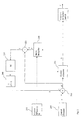
- Figure 2 shows a block diagram of a general control system for controlling a vehicle according to the present invention.
- the control system combines control allocation technology and phase compensating technology.
- the letter "k” is used to denote number of control requirements, i.e., the number of components in a control demand vector.
- the letter “m” is used to denote number of actuators.
- a control demand device 205 provides a control demand vector u of dimension k.
- the control demand device 205 receives input from the pilot of the vehicle, i.e., it receives desired values of motion parameters via control sticks, steering wheels, pedals or the like as known in the art. It should be emphasized that the invention is not dependent on receiving motion parameters from a pilot, they may for example also be provided from a control unit of an autonomous vehicle or of a remotely operated vehicle or the like.
- the control demand may be expressed in different terms depending on application. In a fighter application e.g., the control demand may be expressed in terms of a plurality of angular accelerations.
- the control demand vector u is fed to a positive input of a first summation unit 210.
- Said first summation unit 210 also receives input from a filter unit 240.We will return to this filter unit 240 later on.
- the output of the first summation unit 210 is a modified control demand vector u' of dimension k, representing modified control demands. Said vector u' of modified control demands is fed via connections between the units to, on the one hand a control allocation unit 220 and, on the second hand, also to a second summation unit 225.
- the control allocation unit 220 allocates and distributes m actuator commands i.e., the output from the control allocation unit 220 is an actuator command signal vector, here called x, of dimension m.
- x actuator command signal vector
- the actuator command signal vector x is also fed to a matrix multiplication unit 230, which matrix multiplication unit 230, forms the matrix multiplication product B*x.
- the symbol "*" is here used to express a matrix multiplication operator.
- the matrix B is a control efficiency matrix of dimension k*m. The roles of the control efficiency matrix B will be further explained below.
- the output B*x from the matrix multiplication unit 230 we can call an estimated vehicle behaviour, represented by an estimated behaviour signal vector y' of dimension k.
- the estimated behaviour signal vector is fed to the second summation unit 225, which forms a difference between the estimated behaviour y' and the modified control demand u'.
- this difference we call this difference "the motion difference signal”, and we denote it ⁇ .
- ⁇ is a vector of dimension k.
- the output from the second summation unit 225 is thus a motion difference signal called ⁇ .
- the motion difference signal ⁇ can be said to represent an estimated difference between the (motion) control demand of the pilot of the vehicle on the vehicle and the expected motion parameters delivered by the vehicle when responsing to such a control demand. During normal flight this difference is non existent or very small. During advanced manoeuvres however, it may be significant.
- the motion difference signal ⁇ is fed to an amplification unit 235, where it is multiplied with amplification matrix M of dimension k*k.
- the amplified signal i.e., the output from the amplification unit 235 is subsequently fed to a filter unit 240, which unit applies a phase influencing filter, represented in fig. 2 by a first order low-pass filter algorithm 1/(sT + 1), on the amplified motion difference signal vector ⁇ .
- a filter unit 240 which unit applies a phase influencing filter, represented in fig. 2 by a first order low-pass filter algorithm 1/(sT + 1), on the amplified motion difference signal vector ⁇ .
- the filter unit provides filtering means to filter each component of an incoming signal vector independent of each other.
- time constants (T) of the filter unit 240 for low-pass filtering may be different for different components of the amplified motion difference signal vector ⁇ .
- filter constants are chosen and adjusted such that certain preferred behaviour results when the vehicle is forced beyond the limits of the actuators.
- Asymptotically stable filters are preferably used, such as first order low-pass filters.
- phase altered motion difference signal represented by a vector ⁇ is formed, constituting the output from the filter unit 240.
- the phase altered motion difference signal vector ⁇ is then fed to the first summation unit 210, and the feedback loop is closed.
- the input signal to the filter unit 240 i.e., the amplified motion difference signal vector
- the amplified motion difference signal vector when the input signal to the filter unit 240, i.e., the amplified motion difference signal vector, is zero, i.e., when all components ⁇ 1 to ⁇ k are zero, that is, when the difference signal vector ⁇ between estimated behaviour signal vector y' and modified control demand signal vector u' is zero, there should be no feedback.
- the feedback signal is not zero but will converge towards zero if the amplified motion difference signal vector is zero, thereby diminishing the feedback.
- the filters of the filter unit 240 it is important, therefore, for the filters of the filter unit 240 to be truly stable, and for the output signal ⁇ (phase altered motion difference signal vector ⁇ ) from the filter unit 240 to decay towards zero when the input signal to the filter is zero, like e.g. an infinite impulse filter.
- control efficiency matrix expresses how efficient each actuator is to bring about a certain control demand, which in turn is dependent on the design of the specific vehicle and actuators in question.
- the control efficiency matrix B is a dynamic piece of information that is continuously being recalculated. In the case of an aircraft, these recalculations are based on current speed, angle of attack and angle of sideslip sensor signals, air density/pressure, fault signals, and other sensor signals being relevant for actuator efficiency.
- the control allocation unit 220 uses the modified control demand signal vector u' of dimension k and the control efficiency matrix B to produce an actuator command signal vector x. This is done by a control allocation method selected from a group of methods used to solve the so called control allocation problem, which in short can be defined as the problem of finding the actuator command signal vector that, given the control efficiency matrix and the actuator limitations, would bring about a motion pattern of the vehicle as represented by a control demand signal vector.
- One of the features of the present invention is to modify the control demand signal vector when an original control demand signal vector represents a demanded motion pattern that simply cannot or will not be realised by the vehicle due to e.g. performance limits, may they be real or set by certain rules or provisions.
- the present invention is not dependent on a particular control allocation method to be used, it could for example be an optimization based control allocation method, a direct control allocation method or a daisy chain control allocation method as described for example in " Backstepping and Control Allocation with Applications to Flight Control" by Ola Härkeg ⁇ rd pages 114-122 .
- the control allocator unit 220 makes the best from the situation according to the control allocation method used as mentioned above, for producing an actuator command signal vector x.
- the actuator command signal vector x can be fed in parallel to the actuators and to a matrix multiplier unit 230 as described above.
- the matrix multiplier unit 230 calculates an estimated behaviour signal vector y', which is directly comparable with the modified control demand vector u'.
- the modified control demand vector u' is not yet compensated and therefore identical to u and the difference signal ⁇ become negative.
- the difference signal is used to decrease the input signal u' to the control allocator 220 to a value smaller than the control demand vector u.
- Fig. 3 is a flowchart of a method for vehicle control according to a preferred embodiment of the present invention. The method comprises the following steps:
- the steps of the method are then repeated multiple times each second as is known in the art.
- the method may be implemented in software or hardware or in a combination of hardware and software as is realised by a person skilled in the art.
- One advantage with the above solution is that it is possible to employ the advantages with control allocation techniques and at the same time provide phase compensation when the control demands not can be met by use of the control allocation technology.
- Another advantage is that a pilot perceived reduction of the speed of actuator response due to performance limitations is transformed to a reduction in amplification, which will reduce or totally eliminate pilot in the loop oscillations.
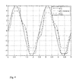
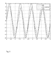
- Fig. 4 and 5 shows diagrams of a two-dimensional simulation run for demonstrating the performance of a vehicle control systems according to the present invention compared to a prior art system fed with the same control demand signal vector. The following notation is used:
- Fig. 4 shows a diagram for the first component.
- the control allocation method uses hard optimisation towards the input signal, i.e., the control demand signal vector component u(1). This is why the estimated behaviour signal component y'(1) looks a bit distorted. Nevertheless, the estimated behaviour signal (y'(1)) for a system according to the invention follows better, i.e., with less phase delay, than the prior art system (y'(1) nominal). It can be seen that the phase loss can be said to be converted to a (small) amplification loss instead.
- Fig. 5 shows a diagram for the second component.
- the control allocation method uses higher penalty for deviations from u(2) than u(1). It can be seen that the phase loss (time delay) is considerably lower for the estimated behaviour signal second component for the system according to the invention (y'(2)) than for the prior art system (y'(2) nominal).
Landscapes
- Engineering & Computer Science (AREA)
- Health & Medical Sciences (AREA)
- Artificial Intelligence (AREA)
- Computer Vision & Pattern Recognition (AREA)
- Evolutionary Computation (AREA)
- Medical Informatics (AREA)
- Software Systems (AREA)
- Physics & Mathematics (AREA)
- General Physics & Mathematics (AREA)
- Automation & Control Theory (AREA)
- Feedback Control In General (AREA)
- Fluid-Pressure Circuits (AREA)
Abstract
Description
- The present invention relates to the field of vehicle control. In particular it relates to methods and apparatus for improving performance and stability in a control system where the time derivative of an output from a subsystem is limited, resulting in that an input cannot be fulfilled. More particularly it relates to such methods and apparatus for improving control systems provided with some kind of control allocation.
- In control theory and praxis, a control system of a vehicle can be viewed upon as a system performing two subsequent separate steps;
a first step comprising calculating a control demand based on operator commands and feedback signals and taking into consideration requirements on stability and performance; and
a second step comprising calculating and distributing actuator signals to the available actuators, based on the control demand, such that said control demand will be realised. A more detailed explanation can be found in e.g., Härkegård, O; Backstepping and Control Allocation with Applications to Flight Control. Linköping University 2003. pp105-107. -
Figure 1 shows a block diagram illustrating signal pathways in a prior art flight control system design based on such a division into two separate steps. When developing a such control system process feedback couplings may be constructed using any suitable design method such as e.g. PID (Proportional-Integrating-Derivating Control), linear quadratic minimization (LQ), exact linearization (NDI), adaptive methods etc.). The problem of distribution does not have to be considered, when designing software/hardware realising such a first step. - The design of software/hardware realising the second step can then be performed without having to consider the actual control laws used. In the second step, the distribution of the control demand is performed by distributing to the available actuators control signals that, when having had their effect on said available actuators, fulfils said control demand on the vehicle. This can be achieved by a variety of available methods. Either a fixed (non varying) function, in the linear case a matrix, can be used. In this case the distribution will not be able to adapt to varying effectiveness of the different actuators throughout the envelop of the controlled system. Methods are also available which adapt to the effectiveness of the actuators (control surfaces in aircraft case) and also redistributes the required control if any of the actuators should fail or reach its limitation in position or velocity. These methods usually optimize the actuator performance using the given effectiveness of each actuator, under the given constraints, using some norm (2norm, 1norm or infinity norm).
- Further in the system of
fig. 1 , acontrol allocation unit 115 takes said control demand and allocates and distributes actuator signal to available actuators of avehicle 120. During this allocation and distribution, thecontrol allocation unit 115 considers each actuator's ability to create a certain type of control effect, and modifies the distribution accordingly. - Such an allocation and distribution makes it possible to handle, independent of system total performance, varying actuator performance, e.g. rudder efficiency, but also actuator position and speed limitations, and also faults in actuators. Such faults may include loss, i.e., control surface moves freely, and locking i.e., control surface gets stuck in an arbitrary position.
- Methods for control allocation and distribution of a control demand, are disclosed in e.g doctoral dissertation "Backstepping and Control Allocation with Applications to Flight Control" , mentioned above.
- Prior art control allocation systems have a tendency to build up an undesired phase loss, when said control allocation systems together with available actuators no longer are able to fulfil current control demand. Non-considered phase loss in a regulatory system is highly undesired. With an operator in the control loop, the operator may experience a feeling of being disconnected from the system. Using aircraft design vocabulary this is called "Pilot In the Loop Oscillations" and they are feared by both pilots and designers.
-
WO 99/09461 to Buck -
US 5,528,119 to Rundqwist et al , discloses a method and a device for executing phase compensation in a motor-driven vehicle without control allocation. - With reference to
fig. 2 , the present invention in its most general form relates to a control system for receiving k input signals, which may be represented by an input vector u, and for providing m output signals, which may be represented by an output vector x. The system provides the m output signals based on k modified input signals u', related to said k input signals, the m output signals being suitable for feeding m actuators. The control system is further provided with means for computing said m output signals such that when said m output signals are effected by said m actuators, the actuators give rise to changes in vehicle attitude status, said status will comply with a control demand expressed e.g., as a demanded attitude status described by the k input signals when this is within the performance limits of the actuators, and to comply with them to a lesser extent, keeping the vehicle controllable, when the k input signals describe a demanded attitude status outside the performance limits of the actuators. - Means are also provided for forming an estimated motion behaviour y', e.g., an estimated attitude state that comprises k estimated attitude signals. Means are also provided for forming k error signals e1..ek, represented by error vector ε, as the difference between k modified input signals u' and said k estimated motion behavior signals y'1..y'k. Means are also provided for amplifying and phase compensating said k error signals e forming k modified error signals d1..dk. represented by modified error vector d (δ). Means are further provided for feeding back said modified error signals d1..dk by forming the difference u' between the k input signals u1..uk and said modified error signals d1..dk.
- The estimated motion behavior y' calculated from actuator commands x, may not be the same as the one demanded by input signals u. The time derivative of x1 to xm limited in these cases. It is however an advantage that a limited time derivative of x not necessarily means that the estimated motion behavior y' differs from the control demand vector u, i.e., the desired motion behavior, since the dimension of x often is greater than the dimension of u, i.e., m is greater than k.
- Thus, according to a first aspect of the invention a vehicle control system for a vehicle is provided where said system comprises a control allocator for allocating a received control demand by providing actuator control signals derived from said control demand to a plurality of actuators, said system also comprising feedback means comprising a behaviour estimation unit for forming and for feeding back via a feedback loop a feedback signal representative of a difference between a desired vehicle behaviour represented by a control demand signal vector and an estimated vehicle behaviour that would result from applying said actuator signals at current travel conditions, the feedback signal being arranged to modify said control demand signal vector forming a modified control demand signal vector u' such that the modified control demand signal vector u', in the case the control demand signal vector u represents a control demand greater than performance limits of the vehicle under current conditions, will come to represent a control demand within said performance limits when the feedback signal takes effect.
- The system is provided with an input for receiving the control demand signal vector u and an output for outputting the actuator control signals, and where the feedback loop for calculating and feeding back the feedback signal representative of a difference between the control demand signal vector and an estimated vehicle behaviour also comprises a transfer function means comprising asymptotically stable filters.
- The vehicle control system may further comprise a control efficiency unit keeping and updating information regarding the efficiency of the actuators of the vehicle, and where behaviour estimation unit uses information from said control efficiency unit to calculate the estimated vehicle behaviour.
- According to another aspect the control allocator is devised to form an actuator command signal vector, and the feedback means comprises a matrix multiplication unit for forming an estimated behaviour signal vector, the output of said matrix multiplication unit is connected to an input of a first summation unit for forming a motion difference signal vector, an output of said summation unit being connected to an amplification unit, an output from the amplification unit is connected to an input of a filter unit for forming a phase altered motion difference signal vector, an output of said filter unit is connected to an input of a second summation unit for forming a modified control demand signal vector as a difference between a control demand signal vector and said phase altered motion difference signal vector, the output of said second summation unit being connected to the input of the first summation unit and to an input of the control allocator.
- According to yet a further aspect, the vehicle control system comprises a control efficiency matrix unit and a matrix multiplication unit that uses a control efficiency matrix of the control efficiency matrix unit to form an estimated behaviour signal vector by matrix multiplication of the actuator command signal vector and the control efficiency matrix.
- The vehicle control system where control allocation may be performed by a control allocation method selected from a group of control allocation methods consisting of optimization based control allocation method, direct control allocation method and daisy chain control allocation method.
- According to a further aspect, a vehicle control system is provided where said the unit comprises a number of asymptotically stable low pass filters for filtering each component of an input signal vector to the filter unit.
- The vehicle control system where the filter unit comprises a number of first order low pass filters for filtering each component of an input signal vector to the filter unit.
According to another aspect the invention provides a method for controlling a vehicle having a plurality of actuators to influence its travel, the method comprising the following steps: - obtaining a control demand representative of a desired vehicle behaviour ;
- allocating actuators, i.e., distributing actuator commands based on said control demand by means of a control allocation method;
- forming an estimated vehicle behaviour based on actuator commands;
- forming a behaviour difference between the control demand and the estimated vehicle behaviour;
- filtering the behaviour difference forming a filtered behaviour difference;
- feeding back the filtered behaviour difference to modify the control demand forming a modified control demand;
- using the modified control demand as a basis for allocating actuators;
- The method of above where the step of forming an estimated vehicle behaviour based on actuator commands involves use of information from a control efficiency unit keeping and updating information regarding the efficiency of the actuators of the vehicle under current travel conditions.
- The steps of the method may be detailed as follows:
- obtaining a control demand signal vector;
- obtaining a phase altered motion difference signal vector;
- forming a modified demand signal vector by subtracting the phase altered motion difference signal vector from the control demand signal vector;
- obtaining a control efficiency matrix;
- forming an actuator command signal vector by performing control allocation based on the modified demand signal vector and on the control efficiency matrix;
- controlling the vehicle by feeding the actuators with the actuator command signal vector;
- forming an estimated behaviour signal vector by matrix multiplying the actuator command signal vector with the control efficiency matrix ;
- forming a motion difference signal vector by subtracting the modified control demand signal vector from the estimated behaviour signal vector;
- forming the phase altered motion difference signal vector by amplifying and filtering the motion difference signal vector;
- feeding back the phase altered motion difference signal vector.
- The control allocation of the method may be performed by a control allocation method selected from a group of control allocation methods consisting of optimization based control allocation method, direct control allocation method and daisy chain control allocation method.
- These and other features, aspects and advantages of the present invention will become better understood with reference to the following description, appended claims, and accompanying drawings where
-
Fig. 1 is a block diagram showing a structure of a flight control system. -
Fig. 2 is a block diagram showing a control system provided with control allocation means and feedback means for a general system according to the present invention. -
Fig. 3 shows a flowchart representing a method according to an embodiment of the invention. -
Fig. 4 and5 shows diagrams of simulation runs for demonstrating the performance of a control system according to an embodiment of the invention compared to a prior art system. -
Figure 1 shows a block diagram, demonstrating signal flow within a vehicle control allocation control system according to known technology. An operator, e.g. , apilot 105 or a travel control unit of an autonomous vehicle communicates desired values of vehicle state or waypoints or reference values in speed, altitude and course to the vehicle control system by some means e.g. by control stick movements, pedal movements or by conveying suitable signals, as in the case with an autonomous vehicle. The travel control system comprises an OperatorCommand Shaping Unit 110 that receives said desired values and filters them. - The filtered desired values are subsequently fed to a summation unit 112 - In the
summation unit 112 feedback signals and the filtered desired values are added together forming a sum. The sum may e.g. represent ordered angular accelerations of vehicle attitude angles. Acontrol allocator 115 translates the ordered angular accelerations of vehicle attitude angles into actuator control signals for control surfaces of thevehicle 120. The inner detailed working of a control allocator is not the subject of the present invention and will not be described here. The reader is referred to the art literature. Subsequently, thevehicle 120 alters its attitude angles due to the position and change of position of said control surfaces. Attitude angles, and/or attitude angle velocities, and/or attitude angle accelerations are measured and fed as measurement signals 125 to asignal processing unit 130, whichunit 130 feeds feedback signals 135 to afeedback couplings unit 100, which in turn delivers appropriate values for adding to thesummation unit 112. - Control systems having control allocators of commercially available systems, although working well during most conditions, have a tendency to under certain circumstances introduce phase delays and "Pilot in the Loop Oscillations", as mentioned above. In order to prevent such phase delays and Pilot in the Loop Oscillations a system and a method according to the present invention is provided.
-
Figure 2 shows a block diagram of a general control system for controlling a vehicle according to the present invention. The control system combines control allocation technology and phase compensating technology. For the purpose of the present application the letter "k" is used to denote number of control requirements, i.e., the number of components in a control demand vector. The letter "m" is used to denote number of actuators. - A
control demand device 205 provides a control demand vector u of dimension k. Thecontrol demand device 205 receives input from the pilot of the vehicle, i.e., it receives desired values of motion parameters via control sticks, steering wheels, pedals or the like as known in the art. It should be emphasized that the invention is not dependent on receiving motion parameters from a pilot, they may for example also be provided from a control unit of an autonomous vehicle or of a remotely operated vehicle or the like. The control demand may be expressed in different terms depending on application. In a fighter application e.g., the control demand may be expressed in terms of a plurality of angular accelerations. - The control demand vector u is fed to a positive input of a
first summation unit 210. Saidfirst summation unit 210 also receives input from a filter unit 240.We will return to thisfilter unit 240 later on. - The output of the
first summation unit 210 is a modified control demand vector u' of dimension k, representing modified control demands. Said vector u' of modified control demands is fed via connections between the units to, on the one hand acontrol allocation unit 220 and, on the second hand, also to asecond summation unit 225. Thecontrol allocation unit 220 allocates and distributes m actuator commands i.e., the output from thecontrol allocation unit 220 is an actuator command signal vector, here called x, of dimension m. The function and characterising features of the control allocation unit will be further explained below. - The actuator command signal vector x is also fed to a
matrix multiplication unit 230, whichmatrix multiplication unit 230, forms the matrix multiplication product B*x. The symbol "*" is here used to express a matrix multiplication operator. The matrix B is a control efficiency matrix of dimension k*m. The roles of the control efficiency matrix B will be further explained below. - The output B*x from the
matrix multiplication unit 230, we can call an estimated vehicle behaviour, represented by an estimated behaviour signal vector y' of dimension k. The estimated behaviour signal vector is fed to thesecond summation unit 225, which forms a difference between the estimated behaviour y' and the modified control demand u'. For the purpose of this application we call this difference "the motion difference signal", and we denote it ε. ε is a vector of dimension k. - The output from the
second summation unit 225 is thus a motion difference signal called ε .The motion difference signal ε can be said to represent an estimated difference between the (motion) control demand of the pilot of the vehicle on the vehicle and the expected motion parameters delivered by the vehicle when responsing to such a control demand. During normal flight this difference is non existent or very small. During advanced manoeuvres however, it may be significant. - The motion difference signal ε is fed to an
amplification unit 235, where it is multiplied with amplification matrix M of dimension k*k. - The amplified signal, i.e., the output from the
amplification unit 235 is subsequently fed to afilter unit 240, which unit applies a phase influencing filter, represented infig. 2 by a first order low-pass filter algorithm 1/(sT + 1), on the amplified motion difference signal vector ε. It should be understood that the filter unit provides filtering means to filter each component of an incoming signal vector independent of each other. For example, time constants (T) of thefilter unit 240 for low-pass filtering may be different for different components of the amplified motion difference signal vector ε. This may be accomplished by matrix multiplication of said amplified motion difference signal vector ε with a filter matrix having the following representation
- That is, a having filters as diagonal elements and zeroes outside the diagonal. In a preferred embodiment filter constants are chosen and adjusted such that certain preferred behaviour results when the vehicle is forced beyond the limits of the actuators. Asymptotically stable filters are preferably used, such as first order low-pass filters.
- Thus a phase altered motion difference signal, represented by a vector δ is formed, constituting the output from the
filter unit 240. The phase altered motion difference signal vector δ is then fed to thefirst summation unit 210, and the feedback loop is closed. - In an initial state, when the input signal to the
filter unit 240, i.e., the amplified motion difference signal vector, is zero, i.e., when all components ε1 to εk are zero, that is, when the difference signal vector ε between estimated behaviour signal vector y' and modified control demand signal vector u' is zero, there should be no feedback. In a non-initial state the feedback signal is not zero but will converge towards zero if the amplified motion difference signal vector is zero, thereby diminishing the feedback. It is important, therefore, for the filters of thefilter unit 240 to be truly stable, and for the output signal δ (phase altered motion difference signal vector δ) from thefilter unit 240 to decay towards zero when the input signal to the filter is zero, like e.g. an infinite impulse filter. - As is known in the art, the control efficiency matrix expresses how efficient each actuator is to bring about a certain control demand, which in turn is dependent on the design of the specific vehicle and actuators in question. The control efficiency matrix B is a dynamic piece of information that is continuously being recalculated. In the case of an aircraft, these recalculations are based on current speed, angle of attack and angle of sideslip sensor signals, air density/pressure, fault signals, and other sensor signals being relevant for actuator efficiency.
- The
control allocation unit 220 uses the modified control demand signal vector u' of dimension k and the control efficiency matrix B to produce an actuator command signal vector x. This is done by a control allocation method selected from a group of methods used to solve the so called control allocation problem, which in short can be defined as the problem of finding the actuator command signal vector that, given the control efficiency matrix and the actuator limitations, would bring about a motion pattern of the vehicle as represented by a control demand signal vector. One of the features of the present invention is to modify the control demand signal vector when an original control demand signal vector represents a demanded motion pattern that simply cannot or will not be realised by the vehicle due to e.g. performance limits, may they be real or set by certain rules or provisions. The present invention is not dependent on a particular control allocation method to be used, it could for example be an optimization based control allocation method, a direct control allocation method or a daisy chain control allocation method as described for example in "Backstepping and Control Allocation with Applications to Flight Control" by Ola Härkegård pages 114-122. - When the change in any of the control demand signal vector components u1 to uk exceeds what is possible for the vehicle to achieve under current conditions, in spite of efficient control allocation, the signal ε will be different from zero. Indeed, if the modified control demand signal vector u' is increasing to a level where actuators cannot bring the vehicle in compliance with said demand, the
control allocator unit 220 makes the best from the situation according to the control allocation method used as mentioned above, for producing an actuator command signal vector x. The actuator command signal vector x can be fed in parallel to the actuators and to amatrix multiplier unit 230 as described above. Thematrix multiplier unit 230 calculates an estimated behaviour signal vector y', which is directly comparable with the modified control demand vector u'. In an initial stage, the modified control demand vector u' is not yet compensated and therefore identical to u and the difference signal ε become negative. After amplification and filtering the difference signal is used to decrease the input signal u' to thecontrol allocator 220 to a value smaller than the control demand vector u. - It is realised that the same functionality is achieved by forming an alternative motion difference signal vector ε' as u'-y' (instead of y'-u') and subtracting ε', or corresponding filtered motion difference signal vector δ', i.e feeding δ' to a negative input of the
first summation unit 210. -
Fig. 3 is a flowchart of a method for vehicle control according to a preferred embodiment of the present invention. The method comprises the following steps: - obtaining (305) a control demand signal vector u;
- obtaining (310) a phase altered motion difference signal vector δ;
- forming (315) a modified demand signal vector u' by subtracting the phase altered motion difference signal vector δ from the control demand signal vector u;
- obtaining (320) a control efficiency matrix B;
- forming (325) an actuator command signal vector x by performing control allocation based on the modified demand signal vector u' and on the control efficiency matrix B;
- distributing (330) actuator command signal vector x components x1, x2 etc to corresponding actuators;
- forming (335) an estimated behaviour signal vector y' by matrix multiplying the actuator command signal vector x with the control efficiency matrix B;
- forming (340) a motion difference signal vector ε by subtracting the modified control demand signal vector u' from the estimated behaviour signal vector y';
- forming (345) the phase altered motion difference signal vector δ by amplifying and filtering the motion difference signal vector ε
- The steps of the method are then repeated multiple times each second as is known in the art. The method may be implemented in software or hardware or in a combination of hardware and software as is realised by a person skilled in the art.
- One advantage with the above solution is that it is possible to employ the advantages with control allocation techniques and at the same time provide phase compensation when the control demands not can be met by use of the control allocation technology. Another advantage is that a pilot perceived reduction of the speed of actuator response due to performance limitations is transformed to a reduction in amplification, which will reduce or totally eliminate pilot in the loop oscillations.
-
Fig. 4 and5 shows diagrams of a two-dimensional simulation run for demonstrating the performance of a vehicle control systems according to the present invention compared to a prior art system fed with the same control demand signal vector. The following notation is used: - u(1) is first component of control demand signal vector u
- u(2) is second component of control demand signal vector u
- y'(1) nominal is the first component of an estimated behaviour signal vector y' for a prior art system
- y'(2) nominal is the second component of an estimated behaviour signal vector y' for a prior art system;
- y'(1) is the first component of an estimated behaviour signal vector y' for a system according to an embodiment of the present invention
- y'(2) is the second component of an estimated behaviour signal vector y' for a a system according to an embodiment of the present invention;
-
Fig. 4 shows a diagram for the first component. The control allocation method uses hard optimisation towards the input signal, i.e., the control demand signal vector component u(1). This is why the estimated behaviour signal component y'(1) looks a bit distorted. Nevertheless, the estimated behaviour signal (y'(1)) for a system according to the invention follows better, i.e., with less phase delay, than the prior art system (y'(1) nominal). It can be seen that the phase loss can be said to be converted to a (small) amplification loss instead. -
Fig. 5 shows a diagram for the second component. The control allocation method uses higher penalty for deviations from u(2) than u(1). It can be seen that the phase loss (time delay) is considerably lower for the estimated behaviour signal second component for the system according to the invention (y'(2)) than for the prior art system (y'(2) nominal).
Claims (12)
- A vehicle control system for a vehicle characterised in that said system comprises a control allocator (220) for allocating a received control demand by providing actuator control signals derived from said control demand to a plurality of actuators, said system also comprising feedback means (210, 230, 225, 235, 240) comprising a behaviour estimation unit (230) for forming and for feeding back via a feedback loop a feedback signal representative of a difference between a desired vehicle behaviour represented by a control demand signal vector and an estimated vehicle behaviour that would result from said actuator signals at current travel conditions, the feedback signal being arranged to modify said control demand signal vector forming a modified control demand signal vector u' such that the modified control demand signal vector (u'), in the case the control demand signal vector (u) represents a control demand greater than performance limits of the vehicle under current conditions, will come to represent a control demand within said performance limits when the feedback signal takes effect.
- The vehicle control system according to claim 1 where the system is provided with an input for receiving the control demand signal vector u and an output for outputting the actuator control signals, and where said feedback loop for calculating and feeding back the feedback signal representative of a difference between the control demand signal vector and an estimated vehicle behaviour also comprises a transfer function means (235, 240), and said transfer function means (235, 240) comprises asymptotically stable filters.
- The vehicle control system according to claim 1 also comprising a control efficiency unit (215) keeping and updating information regarding the efficiency of the actuators of the vehicle, and where behaviour estimation unit (230) uses information from said control efficiency unit to calculate the estimated vehicle behaviour.
- The vehicle control system according to claim 2 or 3 where said control allocator (220) is devised to form an actuator command signal vector (x), and where said feedback means comprises a matrix multiplication unit (230) for forming an estimated behaviour signal vector (y'), the output of said matrix multiplication unit (230) is connected to an input of a first summation unit (225) for forming a motion difference signal vector (ε), an output of said summation unit (225) being connected to an amplification unit (235), an output from the amplification unit (235) is connected to an input of a filter unit (240) for forming a phase altered motion difference signal vector (δ), an output of said filter unit (240) is connected to an input of a second summation unit (210) for forming a modified control demand signal vector (u') as a difference between a control demand signal vector (u) and said phase altered motion difference signal vector (δ), the output of said second summation unit (210) being connected to the input of the first summation unit (225) and to an input of the control allocator (220).
- The vehicle control system according to claim 4 where said system comprises a control efficiency matrix unit (215) and a matrix multiplication unit (230) that uses a control efficiency matrix (B) of the control efficiency matrix unit (215) to form an estimated behaviour signal vector (y') by matrix multiplication of the actuator command signal vector (x) and the control efficiency matrix (B).
- The vehicle control system according to any of claim 1-5 where control allocation is performed by a control allocation method selected from a group of control allocation methods consisting of optimization based control allocation method, direct control allocation method and daisy chain control allocation method.
- The vehicle control system according to claims 3 to 6 where said filter unit (240) comprises a number of asymptotically stable low pass filters for filtering each component of an input signal vector to the filter unit (240).
- The vehicle control system according to claim 3 to 6 where said filter unit (240) comprises a number of first order low pass filters for filtering each component of an input signal vector to the filter unit (240).
- A method for controlling a vehicle having a plurality of actuators comprising the following steps:- obtaining a control demand representative of a desired vehicle behaviour ;- allocating actuators, i.e., distributing actuator commands based on said control demand by means of a control allocation method;- forming an estimated vehicle behaviour based on actuator commands;- forming a behaviour difference between the control demand and the estimated vehicle behaviour;- filtering the behaviour difference forming a filtered behaviour difference;- feeding back the filtered behaviour difference to modify the control demand forming a modified control demand;- using the modified control demand as a basis for allocating actuators;
- The method according to claim 9 where the step of forming an estimated vehicle behaviour based on actuator commands involves use of information from a control efficiency unit keeping and updating information regarding the efficiency of the actuators of the vehicle under current travel conditions.
- The method according to claim 9, where the steps are detailed as follows:- obtaining (305) a control demand signal vector (u);- obtaining (310) a phase altered motion difference signal vector (δ);- forming (315) a modified demand signal vector (u') by subtracting the phase altered motion difference signal vector (δ) from the control demand signal vector (u);- obtaining (320) a control efficiency matrix (B);- forming (325) an actuator command signal vector (x) by performing control allocation based on the modified demand signal vector (u') and on the control efficiency matrix (B);- controlling the vehicle by feeding the actuators with the actuator command signal vector (x);- forming (335) an estimated behaviour signal vector (y') by matrix multiplying the actuator command signal vector (x) with the control efficiency matrix (B);- forming (340) a motion difference signal vector (ε) by subtracting the modified control demand signal vector (u') from the estimated behaviour signal vector (y');- forming (345) the phase altered motion difference signal vector (δ) by amplifying and filtering the motion difference signal vector (ε);- feeding back (315) the phase altered motion difference signal vector (δ).
- The method for controlling a vehicle according to claim 9 or 10 where control allocation is performed by a control allocation method selected from a group of control allocation methods consisting of optimization based control allocation method, direct control allocation method and daisy chain control allocation method.
Priority Applications (4)
| Application Number | Priority Date | Filing Date | Title |
|---|---|---|---|
| EP07102162A EP1956448B1 (en) | 2007-02-12 | 2007-02-12 | Vehicle control system and method using control allocation and phase compensation |
| AT07102162T ATE524770T1 (en) | 2007-02-12 | 2007-02-12 | SYSTEM AND METHOD FOR VEHICLE CONTROL USING CONTROL ASSIGNMENT AND PHASE COMPENSATION |
| ES07102162T ES2370806T3 (en) | 2007-02-12 | 2007-02-12 | CONTROL SYSTEM OF A VEHICLE AND PROCEDURE THAT USES THE CONTROL ASSIGNMENT AND PHASE COMPENSATION. |
| US12/068,843 US9008939B2 (en) | 2007-02-12 | 2008-02-12 | Vehicle control system and method using control allocation and phase compensation |
Applications Claiming Priority (1)
| Application Number | Priority Date | Filing Date | Title |
|---|---|---|---|
| EP07102162A EP1956448B1 (en) | 2007-02-12 | 2007-02-12 | Vehicle control system and method using control allocation and phase compensation |
Publications (2)
| Publication Number | Publication Date |
|---|---|
| EP1956448A1 true EP1956448A1 (en) | 2008-08-13 |
| EP1956448B1 EP1956448B1 (en) | 2011-09-14 |
Family
ID=38157865
Family Applications (1)
| Application Number | Title | Priority Date | Filing Date |
|---|---|---|---|
| EP07102162A Not-in-force EP1956448B1 (en) | 2007-02-12 | 2007-02-12 | Vehicle control system and method using control allocation and phase compensation |
Country Status (4)
| Country | Link |
|---|---|
| US (1) | US9008939B2 (en) |
| EP (1) | EP1956448B1 (en) |
| AT (1) | ATE524770T1 (en) |
| ES (1) | ES2370806T3 (en) |
Cited By (1)
| Publication number | Priority date | Publication date | Assignee | Title |
|---|---|---|---|---|
| CN112550731A (en) * | 2019-09-10 | 2021-03-26 | 沃科波特有限公司 | Method for controlling an actuator system and aircraft using said method |
Families Citing this family (3)
| Publication number | Priority date | Publication date | Assignee | Title |
|---|---|---|---|---|
| US8763955B1 (en) * | 2009-08-31 | 2014-07-01 | The Boeing Company | Method and apparatus for controlling a refueling drogue |
| US9879667B2 (en) | 2014-03-03 | 2018-01-30 | Danfoss Power Solutions Inc. | Variable load sense spring setting for axial piston open circuit pump |
| US10343685B2 (en) * | 2016-09-28 | 2019-07-09 | Baidu Usa Llc | Physical model and machine learning combined method to simulate autonomous vehicle movement |
Citations (4)
| Publication number | Priority date | Publication date | Assignee | Title |
|---|---|---|---|---|
| US5528119A (en) | 1994-05-30 | 1996-06-18 | Saab Ab | Method and apparatus for phase compensation in a vehicle control system |
| WO1999009461A1 (en) | 1997-08-13 | 1999-02-25 | Saab Ab | Method and apparatus for phase compensation in a vehicle control system |
| WO2001082007A2 (en) | 2000-04-25 | 2001-11-01 | Guided Systems Technologies, Inc. | Adaptive control system having hedge unit and related apparatus and methods |
| US20060027710A1 (en) * | 2004-07-30 | 2006-02-09 | Eugene Lavretsky | Adaptive control in the presence of input constraints |
Family Cites Families (10)
| Publication number | Priority date | Publication date | Assignee | Title |
|---|---|---|---|---|
| DE3688523T2 (en) * | 1985-11-27 | 1994-01-13 | Nippon Denso Co | Motor vehicle air conditioning. |
| US5515828A (en) * | 1994-12-14 | 1996-05-14 | Ford Motor Company | Method and apparatus for air-fuel ratio and torque control for an internal combustion engine |
| US6591169B2 (en) * | 2001-09-27 | 2003-07-08 | The Boeing Company | Method and computer program product for controlling the actuators of an aerodynamic vehicle |
| US8060340B2 (en) * | 2002-04-18 | 2011-11-15 | Cleveland State University | Controllers, observers, and applications thereof |
| US8135531B2 (en) * | 2002-06-12 | 2012-03-13 | Nmhg Oregon, Llc | Predictive vehicle controller |
| WO2005067613A2 (en) * | 2004-01-06 | 2005-07-28 | Deo Hrishikesh V | Suspension system with independent control of ride-height, stiffness and damping |
| US7725199B2 (en) * | 2005-03-02 | 2010-05-25 | Cummins Inc. | Framework for generating model-based system control parameters |
| US7567862B2 (en) * | 2007-08-14 | 2009-07-28 | The Boeing Company | Actuation response oscillation detection monitor |
| US8380473B2 (en) * | 2009-06-13 | 2013-02-19 | Eric T. Falangas | Method of modeling dynamic characteristics of a flight vehicle |
| US8082047B1 (en) * | 2009-11-09 | 2011-12-20 | The Boeing Company | Adaptive control method that compensates for sign error in actuator response |
-
2007
- 2007-02-12 EP EP07102162A patent/EP1956448B1/en not_active Not-in-force
- 2007-02-12 ES ES07102162T patent/ES2370806T3/en active Active
- 2007-02-12 AT AT07102162T patent/ATE524770T1/en not_active IP Right Cessation
-
2008
- 2008-02-12 US US12/068,843 patent/US9008939B2/en not_active Expired - Fee Related
Patent Citations (4)
| Publication number | Priority date | Publication date | Assignee | Title |
|---|---|---|---|---|
| US5528119A (en) | 1994-05-30 | 1996-06-18 | Saab Ab | Method and apparatus for phase compensation in a vehicle control system |
| WO1999009461A1 (en) | 1997-08-13 | 1999-02-25 | Saab Ab | Method and apparatus for phase compensation in a vehicle control system |
| WO2001082007A2 (en) | 2000-04-25 | 2001-11-01 | Guided Systems Technologies, Inc. | Adaptive control system having hedge unit and related apparatus and methods |
| US20060027710A1 (en) * | 2004-07-30 | 2006-02-09 | Eugene Lavretsky | Adaptive control in the presence of input constraints |
Non-Patent Citations (1)
| Title |
|---|
| HARKEGARD O ET AL: "Resolving actuator redundancy-optimal control vs. control allocation", AUTOMATICA, PERGAMON, vol. 41, no. 1, January 2005 (2005-01-01), pages 137 - 144, XP004647534, ISSN: 0005-1098 * |
Cited By (2)
| Publication number | Priority date | Publication date | Assignee | Title |
|---|---|---|---|---|
| CN112550731A (en) * | 2019-09-10 | 2021-03-26 | 沃科波特有限公司 | Method for controlling an actuator system and aircraft using said method |
| CN112550731B (en) * | 2019-09-10 | 2023-12-15 | 沃科波特有限公司 | Method of controlling an actuator system and aircraft using said method |
Also Published As
| Publication number | Publication date |
|---|---|
| EP1956448B1 (en) | 2011-09-14 |
| US9008939B2 (en) | 2015-04-14 |
| ES2370806T3 (en) | 2011-12-22 |
| US20080215191A1 (en) | 2008-09-04 |
| ATE524770T1 (en) | 2011-09-15 |
Similar Documents
| Publication | Publication Date | Title |
|---|---|---|
| US6757570B1 (en) | System and method for adaptive control of uncertain nonlinear processes | |
| Nair et al. | Lyapunov based PD/PID in model reference adaptive control for satellite launch vehicle systems | |
| EP3168143B1 (en) | Method and apparatus for protecting aircraft maximum lift capability | |
| JP5594996B2 (en) | Aircraft control system | |
| EP1956448B1 (en) | Vehicle control system and method using control allocation and phase compensation | |
| CN110398976A (en) | Flying vehicles control method, apparatus and computer readable storage medium | |
| EP0807574B1 (en) | Method and apparatus for turn coordination gain as a function of flap position | |
| CN114114896A (en) | PID parameter design method based on path integral | |
| EP3838746A1 (en) | Feed forward equalization control for active-active redundant actuation systems | |
| An et al. | Prediction of angular acceleration for practical realization of incremental nonlinear trajectory-tracking control for aircrafts | |
| He et al. | Disturbance compensation based piecewise linear control design for perching maneuvers | |
| EP3472681B1 (en) | Control laws for pedal-to-roll coupling | |
| CN114003053A (en) | Fixed wing unmanned aerial vehicle autopilot adaptive control system based on ArduPilot | |
| Franko | Lqr based trajectory control of full envelope, autonomous helicopter | |
| Tran et al. | Back-stepping based flight path angle control algorithm for longitudinal dynamics | |
| Suresh et al. | An on-line learning neural controller for helicopters performing highly nonlinear maneuvers | |
| US10386859B2 (en) | Aircraft flight control method and system | |
| Abdallah et al. | Modelling and simulation of an anti-tank guided missile | |
| Shtessel et al. | Disturbance observer based control: aerospace applications | |
| Apolonskii et al. | Methods for the synthesis of reduced state controllers of linear dynamic systems | |
| Akaryıldız | Flight control law design for fighter aircraftsexploiting nonlinear control techniques | |
| Won et al. | A multi-model approach to gain-scheduling control for agile missile autopilot design | |
| Chudoba et al. | Trim equations of motion for aircraft design: turning flight, pull-up and push-over | |
| Devi | Stability Augmentation in Lateral Directional Dynamics: A Multivariable Approach | |
| Ko et al. | Variable stability system control law development for in-flight simulation of pitch/roll/yaw rate and normal load |
Legal Events
| Date | Code | Title | Description |
|---|---|---|---|
| PUAI | Public reference made under article 153(3) epc to a published international application that has entered the european phase |
Free format text: ORIGINAL CODE: 0009012 |
|
| AK | Designated contracting states |
Kind code of ref document: A1 Designated state(s): AT BE BG CH CY CZ DE DK EE ES FI FR GB GR HU IE IS IT LI LT LU LV MC NL PL PT RO SE SI SK TR |
|
| AX | Request for extension of the european patent |
Extension state: AL BA HR MK RS |
|
| 17P | Request for examination filed |
Effective date: 20090211 |
|
| AKX | Designation fees paid |
Designated state(s): AT BE BG CH CY CZ DE DK EE ES FI FR GB GR HU IE IS IT LI LT LU LV MC NL PL PT RO SE SI SK TR |
|
| 17Q | First examination report despatched |
Effective date: 20090325 |
|
| GRAP | Despatch of communication of intention to grant a patent |
Free format text: ORIGINAL CODE: EPIDOSNIGR1 |
|
| GRAS | Grant fee paid |
Free format text: ORIGINAL CODE: EPIDOSNIGR3 |
|
| GRAA | (expected) grant |
Free format text: ORIGINAL CODE: 0009210 |
|
| AK | Designated contracting states |
Kind code of ref document: B1 Designated state(s): AT BE BG CH CY CZ DE DK EE ES FI FR GB GR HU IE IS IT LI LT LU LV MC NL PL PT RO SE SI SK TR |
|
| REG | Reference to a national code |
Ref country code: GB Ref legal event code: FG4D |
|
| REG | Reference to a national code |
Ref country code: CH Ref legal event code: EP |
|
| REG | Reference to a national code |
Ref country code: IE Ref legal event code: FG4D |
|
| REG | Reference to a national code |
Ref country code: DE Ref legal event code: R096 Ref document number: 602007017123 Country of ref document: DE Effective date: 20111201 |
|
| REG | Reference to a national code |
Ref country code: ES Ref legal event code: FG2A Ref document number: 2370806 Country of ref document: ES Kind code of ref document: T3 Effective date: 20111222 |
|
| REG | Reference to a national code |
Ref country code: NL Ref legal event code: VDEP Effective date: 20110914 |
|
| PG25 | Lapsed in a contracting state [announced via postgrant information from national office to epo] |
Ref country code: FI Free format text: LAPSE BECAUSE OF FAILURE TO SUBMIT A TRANSLATION OF THE DESCRIPTION OR TO PAY THE FEE WITHIN THE PRESCRIBED TIME-LIMIT Effective date: 20110914 Ref country code: SE Free format text: LAPSE BECAUSE OF FAILURE TO SUBMIT A TRANSLATION OF THE DESCRIPTION OR TO PAY THE FEE WITHIN THE PRESCRIBED TIME-LIMIT Effective date: 20110914 Ref country code: LT Free format text: LAPSE BECAUSE OF FAILURE TO SUBMIT A TRANSLATION OF THE DESCRIPTION OR TO PAY THE FEE WITHIN THE PRESCRIBED TIME-LIMIT Effective date: 20110914 |
|
| LTIE | Lt: invalidation of european patent or patent extension |
Effective date: 20110914 |
|
| PG25 | Lapsed in a contracting state [announced via postgrant information from national office to epo] |
Ref country code: LV Free format text: LAPSE BECAUSE OF FAILURE TO SUBMIT A TRANSLATION OF THE DESCRIPTION OR TO PAY THE FEE WITHIN THE PRESCRIBED TIME-LIMIT Effective date: 20110914 Ref country code: GR Free format text: LAPSE BECAUSE OF FAILURE TO SUBMIT A TRANSLATION OF THE DESCRIPTION OR TO PAY THE FEE WITHIN THE PRESCRIBED TIME-LIMIT Effective date: 20111215 Ref country code: AT Free format text: LAPSE BECAUSE OF FAILURE TO SUBMIT A TRANSLATION OF THE DESCRIPTION OR TO PAY THE FEE WITHIN THE PRESCRIBED TIME-LIMIT Effective date: 20110914 Ref country code: SI Free format text: LAPSE BECAUSE OF FAILURE TO SUBMIT A TRANSLATION OF THE DESCRIPTION OR TO PAY THE FEE WITHIN THE PRESCRIBED TIME-LIMIT Effective date: 20110914 Ref country code: CY Free format text: LAPSE BECAUSE OF FAILURE TO SUBMIT A TRANSLATION OF THE DESCRIPTION OR TO PAY THE FEE WITHIN THE PRESCRIBED TIME-LIMIT Effective date: 20110914 |
|
| REG | Reference to a national code |
Ref country code: AT Ref legal event code: MK05 Ref document number: 524770 Country of ref document: AT Kind code of ref document: T Effective date: 20110914 |
|
| PG25 | Lapsed in a contracting state [announced via postgrant information from national office to epo] |
Ref country code: BE Free format text: LAPSE BECAUSE OF FAILURE TO SUBMIT A TRANSLATION OF THE DESCRIPTION OR TO PAY THE FEE WITHIN THE PRESCRIBED TIME-LIMIT Effective date: 20110914 |
|
| PG25 | Lapsed in a contracting state [announced via postgrant information from national office to epo] |
Ref country code: SK Free format text: LAPSE BECAUSE OF FAILURE TO SUBMIT A TRANSLATION OF THE DESCRIPTION OR TO PAY THE FEE WITHIN THE PRESCRIBED TIME-LIMIT Effective date: 20110914 Ref country code: CZ Free format text: LAPSE BECAUSE OF FAILURE TO SUBMIT A TRANSLATION OF THE DESCRIPTION OR TO PAY THE FEE WITHIN THE PRESCRIBED TIME-LIMIT Effective date: 20110914 Ref country code: IS Free format text: LAPSE BECAUSE OF FAILURE TO SUBMIT A TRANSLATION OF THE DESCRIPTION OR TO PAY THE FEE WITHIN THE PRESCRIBED TIME-LIMIT Effective date: 20120114 |
|
| PG25 | Lapsed in a contracting state [announced via postgrant information from national office to epo] |
Ref country code: NL Free format text: LAPSE BECAUSE OF FAILURE TO SUBMIT A TRANSLATION OF THE DESCRIPTION OR TO PAY THE FEE WITHIN THE PRESCRIBED TIME-LIMIT Effective date: 20110914 Ref country code: EE Free format text: LAPSE BECAUSE OF FAILURE TO SUBMIT A TRANSLATION OF THE DESCRIPTION OR TO PAY THE FEE WITHIN THE PRESCRIBED TIME-LIMIT Effective date: 20110914 Ref country code: RO Free format text: LAPSE BECAUSE OF FAILURE TO SUBMIT A TRANSLATION OF THE DESCRIPTION OR TO PAY THE FEE WITHIN THE PRESCRIBED TIME-LIMIT Effective date: 20110914 Ref country code: PT Free format text: LAPSE BECAUSE OF FAILURE TO SUBMIT A TRANSLATION OF THE DESCRIPTION OR TO PAY THE FEE WITHIN THE PRESCRIBED TIME-LIMIT Effective date: 20120116 Ref country code: PL Free format text: LAPSE BECAUSE OF FAILURE TO SUBMIT A TRANSLATION OF THE DESCRIPTION OR TO PAY THE FEE WITHIN THE PRESCRIBED TIME-LIMIT Effective date: 20110914 |
|
| PLBE | No opposition filed within time limit |
Free format text: ORIGINAL CODE: 0009261 |
|
| STAA | Information on the status of an ep patent application or granted ep patent |
Free format text: STATUS: NO OPPOSITION FILED WITHIN TIME LIMIT |
|
| PG25 | Lapsed in a contracting state [announced via postgrant information from national office to epo] |
Ref country code: DK Free format text: LAPSE BECAUSE OF FAILURE TO SUBMIT A TRANSLATION OF THE DESCRIPTION OR TO PAY THE FEE WITHIN THE PRESCRIBED TIME-LIMIT Effective date: 20110914 |
|
| 26N | No opposition filed |
Effective date: 20120615 |
|
| PG25 | Lapsed in a contracting state [announced via postgrant information from national office to epo] |
Ref country code: MC Free format text: LAPSE BECAUSE OF NON-PAYMENT OF DUE FEES Effective date: 20120229 |
|
| REG | Reference to a national code |
Ref country code: CH Ref legal event code: PL |
|
| REG | Reference to a national code |
Ref country code: DE Ref legal event code: R097 Ref document number: 602007017123 Country of ref document: DE Effective date: 20120615 |
|
| PG25 | Lapsed in a contracting state [announced via postgrant information from national office to epo] |
Ref country code: CH Free format text: LAPSE BECAUSE OF NON-PAYMENT OF DUE FEES Effective date: 20120229 Ref country code: LI Free format text: LAPSE BECAUSE OF NON-PAYMENT OF DUE FEES Effective date: 20120229 |
|
| REG | Reference to a national code |
Ref country code: IE Ref legal event code: MM4A |
|
| PG25 | Lapsed in a contracting state [announced via postgrant information from national office to epo] |
Ref country code: IE Free format text: LAPSE BECAUSE OF NON-PAYMENT OF DUE FEES Effective date: 20120212 |
|
| PG25 | Lapsed in a contracting state [announced via postgrant information from national office to epo] |
Ref country code: BG Free format text: LAPSE BECAUSE OF FAILURE TO SUBMIT A TRANSLATION OF THE DESCRIPTION OR TO PAY THE FEE WITHIN THE PRESCRIBED TIME-LIMIT Effective date: 20111214 |
|
| PG25 | Lapsed in a contracting state [announced via postgrant information from national office to epo] |
Ref country code: TR Free format text: LAPSE BECAUSE OF FAILURE TO SUBMIT A TRANSLATION OF THE DESCRIPTION OR TO PAY THE FEE WITHIN THE PRESCRIBED TIME-LIMIT Effective date: 20110914 |
|
| PG25 | Lapsed in a contracting state [announced via postgrant information from national office to epo] |
Ref country code: LU Free format text: LAPSE BECAUSE OF NON-PAYMENT OF DUE FEES Effective date: 20120212 |
|
| PG25 | Lapsed in a contracting state [announced via postgrant information from national office to epo] |
Ref country code: HU Free format text: LAPSE BECAUSE OF FAILURE TO SUBMIT A TRANSLATION OF THE DESCRIPTION OR TO PAY THE FEE WITHIN THE PRESCRIBED TIME-LIMIT Effective date: 20070212 |
|
| REG | Reference to a national code |
Ref country code: FR Ref legal event code: PLFP Year of fee payment: 10 |
|
| REG | Reference to a national code |
Ref country code: FR Ref legal event code: PLFP Year of fee payment: 11 |
|
| REG | Reference to a national code |
Ref country code: FR Ref legal event code: PLFP Year of fee payment: 12 |
|
| PGFP | Annual fee paid to national office [announced via postgrant information from national office to epo] |
Ref country code: ES Payment date: 20190301 Year of fee payment: 13 |
|
| PGFP | Annual fee paid to national office [announced via postgrant information from national office to epo] |
Ref country code: DE Payment date: 20200220 Year of fee payment: 14 Ref country code: IT Payment date: 20200219 Year of fee payment: 14 Ref country code: GB Payment date: 20200218 Year of fee payment: 14 |
|
| PGFP | Annual fee paid to national office [announced via postgrant information from national office to epo] |
Ref country code: FR Payment date: 20200217 Year of fee payment: 14 |
|
| REG | Reference to a national code |
Ref country code: ES Ref legal event code: FD2A Effective date: 20210705 |
|
| PG25 | Lapsed in a contracting state [announced via postgrant information from national office to epo] |
Ref country code: ES Free format text: LAPSE BECAUSE OF NON-PAYMENT OF DUE FEES Effective date: 20200213 |
|
| REG | Reference to a national code |
Ref country code: DE Ref legal event code: R119 Ref document number: 602007017123 Country of ref document: DE |
|
| GBPC | Gb: european patent ceased through non-payment of renewal fee |
Effective date: 20210212 |
|
| PG25 | Lapsed in a contracting state [announced via postgrant information from national office to epo] |
Ref country code: FR Free format text: LAPSE BECAUSE OF NON-PAYMENT OF DUE FEES Effective date: 20210228 Ref country code: GB Free format text: LAPSE BECAUSE OF NON-PAYMENT OF DUE FEES Effective date: 20210212 Ref country code: DE Free format text: LAPSE BECAUSE OF NON-PAYMENT OF DUE FEES Effective date: 20210901 |
|
| PG25 | Lapsed in a contracting state [announced via postgrant information from national office to epo] |
Ref country code: IT Free format text: LAPSE BECAUSE OF NON-PAYMENT OF DUE FEES Effective date: 20210212 |