EP1956192A2 - Gas turbine engine component cooling scheme - Google Patents
Gas turbine engine component cooling scheme Download PDFInfo
- Publication number
- EP1956192A2 EP1956192A2 EP08250455A EP08250455A EP1956192A2 EP 1956192 A2 EP1956192 A2 EP 1956192A2 EP 08250455 A EP08250455 A EP 08250455A EP 08250455 A EP08250455 A EP 08250455A EP 1956192 A2 EP1956192 A2 EP 1956192A2
- Authority
- EP
- European Patent Office
- Prior art keywords
- platform
- airfoil
- cooling
- component
- recited
- Prior art date
- Legal status (The legal status is an assumption and is not a legal conclusion. Google has not performed a legal analysis and makes no representation as to the accuracy of the status listed.)
- Granted
Links
Images


Classifications
-
- F—MECHANICAL ENGINEERING; LIGHTING; HEATING; WEAPONS; BLASTING
- F01—MACHINES OR ENGINES IN GENERAL; ENGINE PLANTS IN GENERAL; STEAM ENGINES
- F01D—NON-POSITIVE DISPLACEMENT MACHINES OR ENGINES, e.g. STEAM TURBINES
- F01D9/00—Stators
- F01D9/02—Nozzles; Nozzle boxes; Stator blades; Guide conduits, e.g. individual nozzles
- F01D9/04—Nozzles; Nozzle boxes; Stator blades; Guide conduits, e.g. individual nozzles forming ring or sector
- F01D9/041—Nozzles; Nozzle boxes; Stator blades; Guide conduits, e.g. individual nozzles forming ring or sector using blades
-
- F—MECHANICAL ENGINEERING; LIGHTING; HEATING; WEAPONS; BLASTING
- F01—MACHINES OR ENGINES IN GENERAL; ENGINE PLANTS IN GENERAL; STEAM ENGINES
- F01D—NON-POSITIVE DISPLACEMENT MACHINES OR ENGINES, e.g. STEAM TURBINES
- F01D25/00—Component parts, details, or accessories, not provided for in, or of interest apart from, other groups
- F01D25/08—Cooling; Heating; Heat-insulation
-
- F—MECHANICAL ENGINEERING; LIGHTING; HEATING; WEAPONS; BLASTING
- F05—INDEXING SCHEMES RELATING TO ENGINES OR PUMPS IN VARIOUS SUBCLASSES OF CLASSES F01-F04
- F05D—INDEXING SCHEME FOR ASPECTS RELATING TO NON-POSITIVE-DISPLACEMENT MACHINES OR ENGINES, GAS-TURBINES OR JET-PROPULSION PLANTS
- F05D2240/00—Components
- F05D2240/80—Platforms for stationary or moving blades
- F05D2240/81—Cooled platforms
-
- F—MECHANICAL ENGINEERING; LIGHTING; HEATING; WEAPONS; BLASTING
- F05—INDEXING SCHEMES RELATING TO ENGINES OR PUMPS IN VARIOUS SUBCLASSES OF CLASSES F01-F04
- F05D—INDEXING SCHEME FOR ASPECTS RELATING TO NON-POSITIVE-DISPLACEMENT MACHINES OR ENGINES, GAS-TURBINES OR JET-PROPULSION PLANTS
- F05D2260/00—Function
- F05D2260/20—Heat transfer, e.g. cooling
- F05D2260/221—Improvement of heat transfer
Definitions
- the present invention generally relates to a gas turbine engine, and more particularly to a cooling scheme for a gas turbine engine component.
- Gas turbine engines typically include a compressor section, a combustor section and a turbine section. Air is pressurized in the compressor section and is mixed with fuel and burned in the combustor section to add energy to expand the air and accelerate the airflow into the turbine section. The hot combustion gases that exit the combustor section flow downstream through the turbine section, which extracts kinetic energy from the expanding gases and converts the energy into shaft horsepower to drive the compressor section.
- the turbine section of the gas turbine engine typically includes alternating rows of turbine vanes and turbine blades.
- the turbine vanes and blades typically include at least one platform and an airfoil which extends from the platform.
- the turbine vanes are stationary and function to direct the hot combustion gases that exit the combustor.
- the rotating turbine blades which are mounted on a rotating disk, extract the power required to drive the compressor section. Due to the extreme heat of the hot combustion gases that exit the combustor section, the turbine vanes and blades are exposed to relatively high temperatures. Cooling schemes are known which are employed to cool the platforms and the airfoils of the turbine vanes and blades.
- impingement platform cooling and film cooling are two common methods for cooling the platforms and airfoils of the turbine vanes and blades. Both methods require a dedicated amount of air to cool the platform. Disadvantageously, there is often not enough cooling airflow available to supply both the airfoil and the platforms with a dedicated airflow.
- both impingement platform cooling and film cooling require holes to be drilled through the platforms to facilitate the dedicated airflow needed to cool the platform.
- the holes may be subject to hot gas ingestion due to insufficient backflow margin. Insufficient backflow margin occurs where the supply pressure of the cooling airflow is less than that of the hot combustion gas path. Where this occurs, hot gas ingestion may result (i.e., hot air from the hot combustion gas path enters the cooling passages of the turbine vanes and blades through the cooling holes) thereby negatively effecting the cooling benefits provided by the cooling holes. Further, even if the cooling air supply pressure is sufficient, the drilled cooling holes may cause undesired aerodynamic losses.
- a gas turbine engine component includes a platform and an airfoil extending from the platform.
- the platform includes an outer surface.
- a cover plate is positioned adjacent to the outer surface of the platform.
- a cooling channel extends between the outer surface and the cover plate and receives cooling air to cool the platform and the airfoil.
- a gas turbine engine includes a compressor section, a combustor section and a turbine section.
- the turbine section includes components having a platform and an airfoil extending from the platform.
- the platform includes an outer surface, a cover plate and a cooling channel extending between the outer surface and the cover plate. The cooling channel receives cooling airflow to cool the platform and the airfoil.
- a method of cooling a gas turbine engine component includes creating a cooling channel within a platform of the component, communicating cooling air into the cooling channel to cool the platform, and recycling the cooling airflow used to cool the platform by communicating the cooling airflow from the cooling channel into the airfoil to cool the airfoil.
- Figure 1 illustrates a gas turbine engine 10 which may include (in serial flow communication) a fan section 12, a low pressure compressor 14, a high pressure compressor 16, a combustor 18, a high pressure turbine 20 and a low pressure turbine 22.
- a gas turbine engine 10 which may include (in serial flow communication) a fan section 12, a low pressure compressor 14, a high pressure compressor 16, a combustor 18, a high pressure turbine 20 and a low pressure turbine 22.
- air is pulled into the gas turbine engine 10 by the fan section 12, is pressurized by the compressors 14, 16, and is mixed with fuel and burned in the combustor 18.
- Hot combustion gases generated within the combustor 18 flow through the high and low pressure turbines 20, 22, which extract energy from the hot combustion gases.
- the high pressure turbine 20 utilizes the extracted energy from the hot combustion gases to power the high pressure compressor 16 through a high speed shaft 19
- a low pressure turbine 22 utilizes the energy extracted from the hot combustion gases to power the fan section 12 and the low pressure compressor 14 through a low speed shaft 21.
- the invention is not limited to the two spool gas turbine architecture described and may be used with other architecture such as single spool axial designs, a three spool axial design and other architectures. That is, the present invention is applicable to any gas turbine engine, and for any application.
- the high pressure turbine 20 and the low pressure turbine 22 typically each include multiple turbine stages, with each stage typically including one row of stationary turbine vanes 24 and one row of rotating turbine blades 26. Each stage is supported on a hub mounted to an engine casing 62 which is disposed about an engine longitudinal centerline axis A. Each stage also includes multiple turbine blades 26 supported circumferentially on the hub and turbine vanes 24 supported circumferentially by the engine casing 62.
- the turbine blades 26 and turbine vanes 24 are shown schematically, with the turbine vanes 24 being positioned between each subsequent row of turbine blades 26.
- gas turbine engine component 28 is illustrated in Figure 2 .
- the gas turbine engine component 28 is a turbine vane having an example cooling scheme 25.
- any other gas turbine engine component may benefit from the example cooling scheme 25 illustrated in this specification.
- the gas turbine engine component is not shown to the scale it would be in practice. Instead, the gas turbine engine component 28 and its numerous parts described herein are shown at a scale which simply illustrates their function. A worker in this art having the benefit of this disclosure would be able to determine an appropriate size, shape and configuration of the gas turbine engine component 28.
- the gas turbine engine component 28 includes an outer platform 30, an inner platform 31 and an airfoil 32 extending between the outer platform 30 and the inner platform 31.
- the gas turbine engine component 28 includes a leading edge 36 at the inlet side of the component 28 and a trailing edge 34 at the opposite side of the component 28.
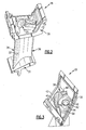
- Figure 3 illustrates an outer surface 38 of the outer platform 30.
- the outer surface 38 is positioned at an opposite side of the outer platform 30 from the airfoil 32.
- An airfoil boss 40 and opposing side rails 42 protrude from the outer surface 38.
- the airfoil boss 40 and the opposing side rails 42 protrude from the outer surface 38 in an opposite direction from the airfoil 32.
- the airfoil boss 40 and the opposing side rails 42 are cast as part of the outer surface 38. That is, the airfoil boss 40, the opposing side rails 42 and the outer surface 38 are a single-piece design. It should be understood, however, that the airfoil boss 40 and the opposing side rails 42 may be formed and attached to the outer surface 38 in any known manner.
- the outer surface 38 may include a borescope hole 44. Inspection equipment, such as fiber optic equipment, may be inserted into the borescope hole 44 to internally inspect the gas turbine engine component 28 for cracks or other damage.
- the airfoil boss 40 also includes a side inlet 46 and a vane inlet 48.
- the side inlet 46 and the vane inlet 48 are openings which extend through the outer platform 30 to communicate airflow to the airfoil 32 of the gas turbine engine component 28, as is further discussed below.
- the opposing side rails 42 are positioned on opposite sides of the outer platform 30, with the airfoil boss 40 positioned between each of the side rails 42.
- the outer surface 38 of the platform 30 further includes platform cooling arrays 50 positioned adjacent to the airfoil boss 40.
- the platform cooling arrays 50 are cast as part of the outer surface 38.
- the platform cooling arrays 50 may be formed in any known manner.
- the platform cooling arrays 50 provide a convective cooling scheme for the gas turbine engine component 28 as cooling airflow travels within the gas turbine engine component 28.
- the platform cooling arrays 50 create turbulence in the cooling airflow as the airflow passes over the arrays 50. The turbulence created results in increased heat transfer between the outer platform 30 and the cooling airflow, as is further discussed below with respect to Figure 8 .
- the platform cooling arrays 50 includes chevron trip strips 51 (see Figure 4 ).
- the chevron trip strips 51 are "V" shaped protrusions having both a thickness and a height.
- the chevron trip strips 51 are spaced in an X direction approximately 0.045 inches (.001143 meters) apart, are spaced in the Y direction approximately 0.150 inches (.00381 meters) apart, and include a height of approximately 0.015 inches (.000381 meters).
- the vertical sides of the chevron trip strips 51 are drafted at an angle of approximately three degrees.
- regular (i.e., normal or skewed) trip strips are utilized as the platform cooling arrays 50.
- the actual spacing, height and draft angle of the chevron or regular trip strips 51 will vary depending upon design specific parameters including but not limited to the size of the gas turbine engine component 28 and the amount of heat transfer required to cool the gas turbine engine component 28.
- the platform cooling arrays 50 includes pin fins 53 (see Figure 5 ).
- the pin fins 53 are conical protrusions extending from the outer surface 38.
- the pin fins 53 include a diameter of approximately 0.040 inches (.001016 meters) and a center to center spacing Z of approximately 0.100 inches (.00254 meters).
- the tops of the pin fins 53 are drafted at an angle of approximately three degrees. The actual spacing, height and draft angle of the pin fins 53 will vary depending upon design specific parameters including but not limited to the size of the gas turbine engine component 28 and the amount of heat transfer required to cool the gas turbine engine component 28. Of course, the listed dimensions are merely examples, and are in no way limiting on this application.
- a cover plate 52 is positioned adjacent to the outer surface 38 and is received on the level surface provided by the airfoil boss 40 and the opposing side rails 42.
- the cover plate 52 is illustrated in phantom lines to show its proximity with the numerous components of the cooling scheme 25, including the outer surface 38, the airfoil boss 40 and the opposing side rails 42.
- the cover plate 52 is welded to the airfoil boss 40 and the opposing side rails 42.
- the cover plate 52 is brazed to the airfoil boss 40 and the opposing side rails 42.
- a cooling channel 54 extends between the outer surface 38 of the outer platform 30 and the cover plate 52. That is, the cooling channel 54 represents the space between the outer surface 38 and the cover plate 52 for which cooling airflow may circulate to cool the platform 30.
- the cover plate also includes an inlet hole 56 for receiving cooling airflow to cool the gas turbine engine component 28.
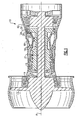
- Figure 7 illustrates a plenum 60 containing cooling air C utilized to cool the gas turbine engine component 28.
- the plenum 60 is formed by the engine casing 62 (or a gas turbine component support structure) which surrounds the gas turbine engine component 28 adjacent to the outer platform 30.
- the engine casing 62 may be a turbine casing which surrounds the turbine vanes 24 and blades 26.
- the plenum 60 is formed by an inner support structure adjacent to the inner platform 31. That is, the cooling airflow C may be downflow fed or upflow fed into the gas turbine engine component 28 to cool the internal components thereof.
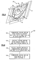
- FIG 8 schematically illustrates a method 100 for cooling a gas turbine engine component 28.
- cooling airflow such as airflow which is bled from the plenum 60 illustrated in Figure 7
- the cooling airflow may also be fed into the inner platform 31 of the gas turbine engine component 28 via an inner support structure.
- the vane inlet 48 is uncovered by or extends through the cover plate 52 such that cooling air may enter the vane inlet 48 to directly cool the internal cooling passages of the airfoil 32.
- the vane inlet 48 is entirely obstructed by the cover plate 52 such that only recycled cooling airflow (i.e., cooling airflow which first circulates within the cooling channel 54 to cool the outer platform 30) is communicated to the airfoil 32 through the side inlet 46 and the vane inlet 48.
- the gas turbine engine component 28 does not include the vane inlet 48, such that the airfoil 32 is cooled entirely by recycled cooling airflow.
- the actual design of the cooling scheme 25 will vary depending upon design specific parameters including but not limited to the amount of cooling airflow required to cool both the airfoil 32 and the platforms 30, 31 of the gas turbine engine component 28.
- the cooling airflow circulates within the cooling channel 54 to cool the outer platform 30 of the gas turbine engine component 28 at step block 104.
- the cooling airflow also circulates over the platform cooling arrays 50 to enhance the amount of heat transfer between the gas turbine engine component 28 and the cooling airflow.
- the cooling airflow utilized to cool the outer platform 30 is recycled by communicating the cooling airflow into the side inlet 46.
- the recycled cooling airflow is communicated to the internal cooling passages of the airfoil 32 of the gas turbine engine component 28.
- the cooling airflow exits the airfoil 32 to enter and cool the inner platform 31 (shown schematically in Figure 9 ).
- example cooling scheme 25 of the gas turbine engine component 28 simultaneously and effectively cools both the platforms 30, 31 and the airfoil 32 of the gas turbine engine component 28. Because drilled cooling holes are not required in the outer platform 30 in example cooling scheme 25, outer platform hot gas ingestion, insufficient backflow margin and significant efficiency reductions are avoided.
Landscapes
- Engineering & Computer Science (AREA)
- Mechanical Engineering (AREA)
- General Engineering & Computer Science (AREA)
- Turbine Rotor Nozzle Sealing (AREA)
Abstract
Description
- The present invention generally relates to a gas turbine engine, and more particularly to a cooling scheme for a gas turbine engine component.
- Gas turbine engines typically include a compressor section, a combustor section and a turbine section. Air is pressurized in the compressor section and is mixed with fuel and burned in the combustor section to add energy to expand the air and accelerate the airflow into the turbine section. The hot combustion gases that exit the combustor section flow downstream through the turbine section, which extracts kinetic energy from the expanding gases and converts the energy into shaft horsepower to drive the compressor section.
- The turbine section of the gas turbine engine typically includes alternating rows of turbine vanes and turbine blades. The turbine vanes and blades typically include at least one platform and an airfoil which extends from the platform. The turbine vanes are stationary and function to direct the hot combustion gases that exit the combustor. The rotating turbine blades, which are mounted on a rotating disk, extract the power required to drive the compressor section. Due to the extreme heat of the hot combustion gases that exit the combustor section, the turbine vanes and blades are exposed to relatively high temperatures. Cooling schemes are known which are employed to cool the platforms and the airfoils of the turbine vanes and blades.
- For example, impingement platform cooling and film cooling are two common methods for cooling the platforms and airfoils of the turbine vanes and blades. Both methods require a dedicated amount of air to cool the platform. Disadvantageously, there is often not enough cooling airflow available to supply both the airfoil and the platforms with a dedicated airflow.
- In addition, both impingement platform cooling and film cooling require holes to be drilled through the platforms to facilitate the dedicated airflow needed to cool the platform. The holes may be subject to hot gas ingestion due to insufficient backflow margin. Insufficient backflow margin occurs where the supply pressure of the cooling airflow is less than that of the hot combustion gas path. Where this occurs, hot gas ingestion may result (i.e., hot air from the hot combustion gas path enters the cooling passages of the turbine vanes and blades through the cooling holes) thereby negatively effecting the cooling benefits provided by the cooling holes. Further, even if the cooling air supply pressure is sufficient, the drilled cooling holes may cause undesired aerodynamic losses.
- Accordingly, it is desirable to provide an improved cooling scheme for a gas turbine engine component which provides efficient and simultaneous cooling of an airfoil and a platform of the gas turbine engine component.
- A gas turbine engine component includes a platform and an airfoil extending from the platform. The platform includes an outer surface. A cover plate is positioned adjacent to the outer surface of the platform. A cooling channel extends between the outer surface and the cover plate and receives cooling air to cool the platform and the airfoil.
- A gas turbine engine includes a compressor section, a combustor section and a turbine section. The turbine section includes components having a platform and an airfoil extending from the platform. The platform includes an outer surface, a cover plate and a cooling channel extending between the outer surface and the cover plate. The cooling channel receives cooling airflow to cool the platform and the airfoil.
- A method of cooling a gas turbine engine component includes creating a cooling channel within a platform of the component, communicating cooling air into the cooling channel to cool the platform, and recycling the cooling airflow used to cool the platform by communicating the cooling airflow from the cooling channel into the airfoil to cool the airfoil.
- The various features and advantages of this invention will become apparent to those skilled in the art from the following detailed description. The drawings that accompany the detailed description can be briefly described as follows.
-
-
Figure 1 illustrates a general perspective view of a gas turbine engine; -
Figure 2 is a perspective view of a gas turbine engine component; -
Figure 3 is a perspective view of a platform of the gas turbine engine component illustrated inFigure 2 ; -
Figure 4 is a first example platform cooling array for the platform of the gas turbine engine component illustrated inFigure 3 ; -
Figure 5 is a second example platform cooling array for the platform of the gas turbine engine component illustrated inFigure 3 ; -
Figure 6 is a second perspective view of the platform of the gas turbine engine component illustrated inFigure 2 ; -
Figure 7 illustrates a cross-sectional view of a plenum containing the cooling airflow utilized to cool the gas turbine engine component illustrated inFigure 2 ; -
Figure 8 is a schematic representation of a cooling scheme for cooling the gas turbine engine component; and -
Figure 9 schematically illustrates the passage of cooling airflow through the gas turbine engine component. -
Figure 1 illustrates agas turbine engine 10 which may include (in serial flow communication) afan section 12, alow pressure compressor 14, ahigh pressure compressor 16, acombustor 18, ahigh pressure turbine 20 and alow pressure turbine 22. During operation, air is pulled into thegas turbine engine 10 by thefan section 12, is pressurized by thecompressors combustor 18. Hot combustion gases generated within thecombustor 18 flow through the high andlow pressure turbines high pressure turbine 20 utilizes the extracted energy from the hot combustion gases to power thehigh pressure compressor 16 through ahigh speed shaft 19, and alow pressure turbine 22 utilizes the energy extracted from the hot combustion gases to power thefan section 12 and thelow pressure compressor 14 through alow speed shaft 21. However, the invention is not limited to the two spool gas turbine architecture described and may be used with other architecture such as single spool axial designs, a three spool axial design and other architectures. That is, the present invention is applicable to any gas turbine engine, and for any application. - The
high pressure turbine 20 and thelow pressure turbine 22 typically each include multiple turbine stages, with each stage typically including one row of stationary turbine vanes 24 and one row of rotatingturbine blades 26. Each stage is supported on a hub mounted to anengine casing 62 which is disposed about an engine longitudinal centerline axis A. Each stage also includesmultiple turbine blades 26 supported circumferentially on the hub and turbine vanes 24 supported circumferentially by theengine casing 62. Theturbine blades 26 and turbine vanes 24 are shown schematically, with the turbine vanes 24 being positioned between each subsequent row ofturbine blades 26. - An example gas
turbine engine component 28 is illustrated inFigure 2 . In one example, the gasturbine engine component 28 is a turbine vane having anexample cooling scheme 25. However, it should be understood that any other gas turbine engine component may benefit from theexample cooling scheme 25 illustrated in this specification. It should be understood that the gas turbine engine component is not shown to the scale it would be in practice. Instead, the gasturbine engine component 28 and its numerous parts described herein are shown at a scale which simply illustrates their function. A worker in this art having the benefit of this disclosure would be able to determine an appropriate size, shape and configuration of the gasturbine engine component 28. - The gas
turbine engine component 28 includes anouter platform 30, aninner platform 31 and anairfoil 32 extending between theouter platform 30 and theinner platform 31. The gasturbine engine component 28 includes a leadingedge 36 at the inlet side of thecomponent 28 and atrailing edge 34 at the opposite side of thecomponent 28. -
Figure 3 illustrates anouter surface 38 of theouter platform 30. Although theouter platform 30 is illustrated, it should be understood that theinner platform 31 may include a similar configuration. Theouter surface 38 is positioned at an opposite side of theouter platform 30 from theairfoil 32. Anairfoil boss 40 and opposingside rails 42 protrude from theouter surface 38. Theairfoil boss 40 and theopposing side rails 42 protrude from theouter surface 38 in an opposite direction from theairfoil 32. In one example, theairfoil boss 40 and the opposing side rails 42 are cast as part of theouter surface 38. That is, theairfoil boss 40, the opposing side rails 42 and theouter surface 38 are a single-piece design. It should be understood, however, that theairfoil boss 40 and the opposing side rails 42 may be formed and attached to theouter surface 38 in any known manner. - Optionally, the
outer surface 38 may include aborescope hole 44. Inspection equipment, such as fiber optic equipment, may be inserted into theborescope hole 44 to internally inspect the gasturbine engine component 28 for cracks or other damage. - The
airfoil boss 40 also includes aside inlet 46 and avane inlet 48. Theside inlet 46 and thevane inlet 48 are openings which extend through theouter platform 30 to communicate airflow to theairfoil 32 of the gasturbine engine component 28, as is further discussed below. The opposing side rails 42 are positioned on opposite sides of theouter platform 30, with theairfoil boss 40 positioned between each of the side rails 42. - The
outer surface 38 of theplatform 30 further includesplatform cooling arrays 50 positioned adjacent to theairfoil boss 40. In one example, theplatform cooling arrays 50 are cast as part of theouter surface 38. However, theplatform cooling arrays 50 may be formed in any known manner. Theplatform cooling arrays 50 provide a convective cooling scheme for the gasturbine engine component 28 as cooling airflow travels within the gasturbine engine component 28. Specifically, theplatform cooling arrays 50 create turbulence in the cooling airflow as the airflow passes over thearrays 50. The turbulence created results in increased heat transfer between theouter platform 30 and the cooling airflow, as is further discussed below with respect toFigure 8 . - In one example, the
platform cooling arrays 50 includes chevron trip strips 51 (seeFigure 4 ). The chevron trip strips 51 are "V" shaped protrusions having both a thickness and a height. In one example, the chevron trip strips 51 are spaced in an X direction approximately 0.045 inches (.001143 meters) apart, are spaced in the Y direction approximately 0.150 inches (.00381 meters) apart, and include a height of approximately 0.015 inches (.000381 meters). In another example, the vertical sides of the chevron trip strips 51 are drafted at an angle of approximately three degrees. In another example, regular (i.e., normal or skewed) trip strips are utilized as theplatform cooling arrays 50. The actual spacing, height and draft angle of the chevron or regular trip strips 51 will vary depending upon design specific parameters including but not limited to the size of the gasturbine engine component 28 and the amount of heat transfer required to cool the gasturbine engine component 28. - In another example, the
platform cooling arrays 50 includes pin fins 53 (seeFigure 5 ). Thepin fins 53 are conical protrusions extending from theouter surface 38. In one example, thepin fins 53 include a diameter of approximately 0.040 inches (.001016 meters) and a center to center spacing Z of approximately 0.100 inches (.00254 meters). In another example, the tops of thepin fins 53 are drafted at an angle of approximately three degrees. The actual spacing, height and draft angle of thepin fins 53 will vary depending upon design specific parameters including but not limited to the size of the gasturbine engine component 28 and the amount of heat transfer required to cool the gasturbine engine component 28. Of course, the listed dimensions are merely examples, and are in no way limiting on this application. - Referring to
Figure 6 , theairfoil boss 40 and the opposing side rails 42 protrude from theouter surface 38 an equal distance to provide a substantially level surface: Acover plate 52 is positioned adjacent to theouter surface 38 and is received on the level surface provided by theairfoil boss 40 and the opposing side rails 42. Thecover plate 52 is illustrated in phantom lines to show its proximity with the numerous components of thecooling scheme 25, including theouter surface 38, theairfoil boss 40 and the opposing side rails 42. In one example, thecover plate 52 is welded to theairfoil boss 40 and the opposing side rails 42. In another example, thecover plate 52 is brazed to theairfoil boss 40 and the opposing side rails 42. - A cooling
channel 54 extends between theouter surface 38 of theouter platform 30 and thecover plate 52. That is, the coolingchannel 54 represents the space between theouter surface 38 and thecover plate 52 for which cooling airflow may circulate to cool theplatform 30. The cover plate also includes aninlet hole 56 for receiving cooling airflow to cool the gasturbine engine component 28. -
Figure 7 illustrates aplenum 60 containing cooling air C utilized to cool the gasturbine engine component 28. In one example, theplenum 60 is formed by the engine casing 62 (or a gas turbine component support structure) which surrounds the gasturbine engine component 28 adjacent to theouter platform 30. For example, theengine casing 62 may be a turbine casing which surrounds the turbine vanes 24 andblades 26. In another example, theplenum 60 is formed by an inner support structure adjacent to theinner platform 31. That is, the cooling airflow C may be downflow fed or upflow fed into the gasturbine engine component 28 to cool the internal components thereof. -
Figure 8 , with continued reference toFigures 1-7 , schematically illustrates amethod 100 for cooling a gasturbine engine component 28. Atstep block 102, cooling airflow, such as airflow which is bled from theplenum 60 illustrated inFigure 7 , is communicated into the gasturbine engine component 28 through theinlet hole 56 of thecover plate 52 attached to theouter platform 30. As stated above, the cooling airflow may also be fed into theinner platform 31 of the gasturbine engine component 28 via an inner support structure. - In one example, the
vane inlet 48 is uncovered by or extends through thecover plate 52 such that cooling air may enter thevane inlet 48 to directly cool the internal cooling passages of theairfoil 32. In another example, thevane inlet 48 is entirely obstructed by thecover plate 52 such that only recycled cooling airflow (i.e., cooling airflow which first circulates within the coolingchannel 54 to cool the outer platform 30) is communicated to theairfoil 32 through theside inlet 46 and thevane inlet 48. In yet another example, the gasturbine engine component 28 does not include thevane inlet 48, such that theairfoil 32 is cooled entirely by recycled cooling airflow. The actual design of thecooling scheme 25 will vary depending upon design specific parameters including but not limited to the amount of cooling airflow required to cool both theairfoil 32 and theplatforms turbine engine component 28. - Once the cooling airflow is communicated through the
inlet hole 56 of thecover plate 52, the cooling airflow circulates within the coolingchannel 54 to cool theouter platform 30 of the gasturbine engine component 28 atstep block 104. The cooling airflow also circulates over theplatform cooling arrays 50 to enhance the amount of heat transfer between the gasturbine engine component 28 and the cooling airflow. Atstep block 106, the cooling airflow utilized to cool theouter platform 30 is recycled by communicating the cooling airflow into theside inlet 46. Upon entering theside inlet 46, the recycled cooling airflow is communicated to the internal cooling passages of theairfoil 32 of the gasturbine engine component 28. Finally, atstep block 108, the cooling airflow exits theairfoil 32 to enter and cool the inner platform 31 (shown schematically inFigure 9 ). - Therefore, the
example cooling scheme 25 of the gasturbine engine component 28 simultaneously and effectively cools both theplatforms airfoil 32 of the gasturbine engine component 28. Because drilled cooling holes are not required in theouter platform 30 inexample cooling scheme 25, outer platform hot gas ingestion, insufficient backflow margin and significant efficiency reductions are avoided. - The foregoing description shall be interpreted as illustrative and not in any limiting sense. A worker of ordinary skill in the art would recognize that certain modifications would come within the scope of this invention. For that reason, the following claims should be studied to determine the true scope and content of this invention.
Claims (20)
- A gas turbine engine component (28), comprising:at least one platform (30) having an outer surface (38);an airfoil (32) extending from said platform (30); anda cover plate (52) positioned adjacent to said outer surface (38) of said at least one platform (30), wherein a cooling channel (54) extends between said outer surface (38) and said cover plate (52), and said cooling channel (54) receives cooling air to cool said at least one platform (30) and said airfoil (32).
- The component as recited in claim 1, wherein said outer surface (38) includes at least one platform cooling array (50).
- The component as recited in claim 2, wherein said at least one platform cooling array (50) includes at least one of a plurality of pin fins (53) formed onto said outer surface (38) and a plurality of trip strips (51) formed onto said outer surface (38).
- The component as recited in any preceding claim, wherein the component is a turbine vane (28).
- The component as recited in any preceding claim, comprising an airfoil boss (40) and opposing side rails (42) which extend from said outer surface (38) in a direction opposite of said airfoil (32), wherein said airfoil boss (40) and said opposing side rails (42) extend an equal distance from said outer surface.
- The component as recited in claim 5, wherein said cover plate (52) is received on and mounted to said airfoil boss (40) and said opposing side rails (42) of said at least one platform (30).
- The component as recited in claim 5 or 6, wherein said airfoil boss (40) includes a side inlet (46) which receives a recycled portion of cooling air communicated through said at least one platform (30) and communicates the recycled portion of the cooling air into said airfoil (32).
- The component as recited in claim 5, 6 or 7, wherein a vane inlet of said airfoil boss (40) is uncovered by said cover plate (52) to receive cooling air and communicate the cooling air directly to said airfoil (32).
- The component as recited in any preceding claim, wherein said at least one platform includes an outer platform (30) and an inner platform (31), wherein said airfoil (32) extends between said outer platform (30) and said inner platform (31).
- The component as recited in any preceding claim, wherein said cover plate (52) includes an inlet hole (56) for receiving the cooling air.
- A gas turbine engine (10), comprising:a compressor section (14, 16), a combustor section (18) and a turbine section (20, 22); andsaid turbine section including at least one component (28) having at least one platform (30) and an airfoil (32) extending from said at least one platform (30), wherein said platform (30) includes an outer surface (38), a cover plate (52) and a cooling channel (54) extending between said outer surface (38) and said cover plate (52), and said cooling channel (54) receives cooling air to cool said at least one platform (30) and said airfoil (32).
- The gas turbine engine as recited in claim 11, wherein said at least one component (28) is a turbine vane.
- The gas turbine engine as recited in claim 11 or 12, comprising at least one platform cooling array (50) formed on said outer surface (38) of said platform (30), wherein said at least one platform cooling array (50) includes at least one of trip strips (51) and pin fins (53).
- The gas turbine engine as recited in any of claims 11 to 13, comprising an airfoil boss (40) and opposing side rails (42) extending from said outer surface (38) in a direction opposite from said airfoil (32), wherein said airfoil boss (40) and said opposing side rails (42) extend an equal distance from said outer surface (38) to receive said cover plate (52).
- The gas turbine engine as recited in claim 14, wherein the cooling air is communicated through an inlet hole (56) in said cover plate (52) and into said cooling channel (54) to cool said at least one platform (30), and subsequently communicated through a side inlet (46) of said airfoil boss (40) to cool said airfoil (32).
- A method of cooling a gas turbine engine component (28), comprising the steps of:(a) creating a cooling channel (54) within a platform (30) of the component (28);(b) communicating cooling airflow into the cooling channel (54) to cool the platform (30); and(c) recycling the cooling airflow by communicating the cooling airflow from the cooling channel (54) into an airfoil (32) of the component (28) subsequent to said step (b).
- The method as recited in claim 16, wherein the component is a turbine vane (28).
- The method as recited in claim 16 or 17, wherein said step (a) comprises the steps of:receiving a cover plate (52) adjacent to an outer surface (38) of the platform (30); andforming the cooling channel (54) between the outer surface (38) and the cover plate (52).
- The method as recited in claim 16, 17 or 18, wherein said step (b) comprises the steps of:communicating the cooling airflow from a plenum (60) into the cooling channel (54); andcommunicating the cooling airflow over platform cooling arrays (50) formed on the platform (30).
- The method as recited in any of claims 16 to 19, wherein said step (c) comprises the step of:communicating the cooling airflow from the cooling channel (54) into a side inlet (46) of an airfoil boss (40) of the platform (30) and further into the airfoil (32).
Applications Claiming Priority (1)
| Application Number | Priority Date | Filing Date | Title |
|---|---|---|---|
| US11/672,604 US7862291B2 (en) | 2007-02-08 | 2007-02-08 | Gas turbine engine component cooling scheme |
Publications (3)
| Publication Number | Publication Date |
|---|---|
| EP1956192A2 true EP1956192A2 (en) | 2008-08-13 |
| EP1956192A3 EP1956192A3 (en) | 2011-10-26 |
| EP1956192B1 EP1956192B1 (en) | 2015-08-05 |
Family
ID=39186753
Family Applications (1)
| Application Number | Title | Priority Date | Filing Date |
|---|---|---|---|
| EP08250455.6A Active EP1956192B1 (en) | 2007-02-08 | 2008-02-07 | Gas turbine engine component cooling scheme |
Country Status (2)
| Country | Link |
|---|---|
| US (3) | US7862291B2 (en) |
| EP (1) | EP1956192B1 (en) |
Cited By (2)
| Publication number | Priority date | Publication date | Assignee | Title |
|---|---|---|---|---|
| WO2019108216A1 (en) * | 2017-12-01 | 2019-06-06 | Siemens Energy, Inc. | Brazed in heat transfer feature for cooled turbine components |
| EP3800327A1 (en) * | 2019-10-04 | 2021-04-07 | Raytheon Technologies Corporation | Cmc vane mate face flange |
Families Citing this family (38)
| Publication number | Priority date | Publication date | Assignee | Title |
|---|---|---|---|---|
| CH700319A1 (en) * | 2009-01-30 | 2010-07-30 | Alstom Technology Ltd | Chilled component for a gas turbine. |
| US8840369B2 (en) * | 2010-09-30 | 2014-09-23 | General Electric Company | Apparatus and methods for cooling platform regions of turbine rotor blades |
| US8777568B2 (en) * | 2010-09-30 | 2014-07-15 | General Electric Company | Apparatus and methods for cooling platform regions of turbine rotor blades |
| US8814517B2 (en) * | 2010-09-30 | 2014-08-26 | General Electric Company | Apparatus and methods for cooling platform regions of turbine rotor blades |
| RU2547351C2 (en) * | 2010-11-29 | 2015-04-10 | Альстом Текнолоджи Лтд | Axial gas turbine |
| US8915712B2 (en) * | 2011-06-20 | 2014-12-23 | General Electric Company | Hot gas path component |
| US8961108B2 (en) | 2012-04-04 | 2015-02-24 | United Technologies Corporation | Cooling system for a turbine vane |
| US9719372B2 (en) | 2012-05-01 | 2017-08-01 | General Electric Company | Gas turbomachine including a counter-flow cooling system and method |
| US9303518B2 (en) * | 2012-07-02 | 2016-04-05 | United Technologies Corporation | Gas turbine engine component having platform cooling channel |
| US9500099B2 (en) * | 2012-07-02 | 2016-11-22 | United Techologies Corporation | Cover plate for a component of a gas turbine engine |
| US9222364B2 (en) * | 2012-08-15 | 2015-12-29 | United Technologies Corporation | Platform cooling circuit for a gas turbine engine component |
| US20140196433A1 (en) | 2012-10-17 | 2014-07-17 | United Technologies Corporation | Gas turbine engine component platform cooling |
| US9476308B2 (en) * | 2012-12-27 | 2016-10-25 | United Technologies Corporation | Gas turbine engine serpentine cooling passage with chevrons |
| WO2015023338A2 (en) * | 2013-05-24 | 2015-02-19 | United Technologies Corporation | Gas turbine engine component having trip strips |
| EP3036405B1 (en) | 2013-08-20 | 2021-05-12 | Raytheon Technologies Corporation | Component for a gas turbine engine, gas turbine engine comprising said component, and method of cooling a component of a gas turbine |
| US10240470B2 (en) | 2013-08-30 | 2019-03-26 | United Technologies Corporation | Baffle for gas turbine engine vane |
| EP3090146B8 (en) * | 2013-11-25 | 2021-04-07 | Raytheon Technologies Corporation | A method for providing coolant to a movable airfoil |
| EP2927430B1 (en) | 2014-04-04 | 2019-08-07 | United Technologies Corporation | Stator vane with a cooled platform for a gas turbine engine |
| WO2016036366A1 (en) | 2014-09-04 | 2016-03-10 | Siemens Aktiengesellschaft | Internal cooling system with insert forming nearwall cooling channels in an aft cooling cavity of a gas turbine airfoil |
| EP2949871B1 (en) * | 2014-05-07 | 2017-03-01 | United Technologies Corporation | Variable vane segment |
| EP3189214A1 (en) | 2014-09-04 | 2017-07-12 | Siemens Aktiengesellschaft | Internal cooling system with insert forming nearwall cooling channels in midchord cooling cavities of a gas turbine airfoil |
| CN107429568B (en) | 2015-03-17 | 2019-11-29 | 西门子能源有限公司 | Internal cooling system with converging-diverging outlet slots in trailing-edge cooling passages for airfoils in turbine engines |
| US20170198602A1 (en) * | 2016-01-11 | 2017-07-13 | General Electric Company | Gas turbine engine with a cooled nozzle segment |
| PL232314B1 (en) | 2016-05-06 | 2019-06-28 | Gen Electric | Fluid-flow machine equipped with the clearance adjustment system |
| US10309246B2 (en) | 2016-06-07 | 2019-06-04 | General Electric Company | Passive clearance control system for gas turbomachine |
| US10392944B2 (en) | 2016-07-12 | 2019-08-27 | General Electric Company | Turbomachine component having impingement heat transfer feature, related turbomachine and storage medium |
| US10605093B2 (en) | 2016-07-12 | 2020-03-31 | General Electric Company | Heat transfer device and related turbine airfoil |
| US10533425B2 (en) | 2017-12-28 | 2020-01-14 | United Technologies Corporation | Doublet vane assembly for a gas turbine engine |
| US10697307B2 (en) | 2018-01-19 | 2020-06-30 | Raytheon Technologies Corporation | Hybrid cooling schemes for airfoils of gas turbine engines |
| US10612406B2 (en) | 2018-04-19 | 2020-04-07 | United Technologies Corporation | Seal assembly with shield for gas turbine engines |
| CN111746801B (en) * | 2019-03-28 | 2024-10-18 | 庞巴迪公司 | Aircraft wing ice protection system and method |
| US10822987B1 (en) | 2019-04-16 | 2020-11-03 | Pratt & Whitney Canada Corp. | Turbine stator outer shroud cooling fins |
| US11021966B2 (en) * | 2019-04-24 | 2021-06-01 | Raytheon Technologies Corporation | Vane core assemblies and methods |
| US11352897B2 (en) | 2019-09-26 | 2022-06-07 | Raytheon Technologies Corporation | Double box composite seal assembly for gas turbine engine |
| US11359507B2 (en) | 2019-09-26 | 2022-06-14 | Raytheon Technologies Corporation | Double box composite seal assembly with fiber density arrangement for gas turbine engine |
| US11220924B2 (en) | 2019-09-26 | 2022-01-11 | Raytheon Technologies Corporation | Double box composite seal assembly with insert for gas turbine engine |
| US11092022B2 (en) * | 2019-11-04 | 2021-08-17 | Raytheon Technologies Corporation | Vane with chevron face |
| US11913348B1 (en) * | 2022-10-12 | 2024-02-27 | Rtx Corporation | Gas turbine engine vane and spar combination with variable air flow path |
Citations (1)
| Publication number | Priority date | Publication date | Assignee | Title |
|---|---|---|---|---|
| US5743708A (en) | 1994-08-23 | 1998-04-28 | General Electric Co. | Turbine stator vane segments having combined air and steam cooling circuits |
Family Cites Families (16)
| Publication number | Priority date | Publication date | Assignee | Title |
|---|---|---|---|---|
| US4017213A (en) * | 1975-10-14 | 1977-04-12 | United Technologies Corporation | Turbomachinery vane or blade with cooled platforms |
| US4466239A (en) | 1983-02-22 | 1984-08-21 | General Electric Company | Gas turbine engine with improved air cooling circuit |
| US4739621A (en) | 1984-10-11 | 1988-04-26 | United Technologies Corporation | Cooling scheme for combustor vane interface |
| US5219894A (en) | 1984-12-25 | 1993-06-15 | Sumitomo Electric Industries, Ltd. | Method for treating the surface of a thin porous film material |
| US5201847A (en) * | 1991-11-21 | 1993-04-13 | Westinghouse Electric Corp. | Shroud design |
| GB9305010D0 (en) | 1993-03-11 | 1993-04-28 | Rolls Royce Plc | A cooled turbine nozzle assembly and a method of calculating the diameters of cooling holes for use in such an assembly |
| DE59709701D1 (en) | 1997-09-15 | 2003-05-08 | Alstom Switzerland Ltd | Platform cooling for gas turbines |
| US6254333B1 (en) * | 1999-08-02 | 2001-07-03 | United Technologies Corporation | Method for forming a cooling passage and for cooling a turbine section of a rotary machine |
| US6517312B1 (en) * | 2000-03-23 | 2003-02-11 | General Electric Company | Turbine stator vane segment having internal cooling circuits |
| GB2365932B (en) | 2000-08-18 | 2004-05-05 | Rolls Royce Plc | Vane assembly |
| US6722138B2 (en) | 2000-12-13 | 2004-04-20 | United Technologies Corporation | Vane platform trailing edge cooling |
| US6508620B2 (en) | 2001-05-17 | 2003-01-21 | Pratt & Whitney Canada Corp. | Inner platform impingement cooling by supply air from outside |
| US6984101B2 (en) * | 2003-07-14 | 2006-01-10 | Siemens Westinghouse Power Corporation | Turbine vane plate assembly |
| US20050135923A1 (en) * | 2003-12-22 | 2005-06-23 | Todd Coons | Cooled vane cluster |
| US7097417B2 (en) | 2004-02-09 | 2006-08-29 | Siemens Westinghouse Power Corporation | Cooling system for an airfoil vane |
| US7097418B2 (en) | 2004-06-18 | 2006-08-29 | Pratt & Whitney Canada Corp. | Double impingement vane platform cooling |
-
2007
- 2007-02-08 US US11/672,604 patent/US7862291B2/en active Active
-
2008
- 2008-02-07 EP EP08250455.6A patent/EP1956192B1/en active Active
-
2010
- 2010-11-24 US US12/953,514 patent/US8403632B2/en active Active
- 2010-11-24 US US12/953,513 patent/US8403631B2/en active Active
Patent Citations (1)
| Publication number | Priority date | Publication date | Assignee | Title |
|---|---|---|---|---|
| US5743708A (en) | 1994-08-23 | 1998-04-28 | General Electric Co. | Turbine stator vane segments having combined air and steam cooling circuits |
Cited By (4)
| Publication number | Priority date | Publication date | Assignee | Title |
|---|---|---|---|---|
| WO2019108216A1 (en) * | 2017-12-01 | 2019-06-06 | Siemens Energy, Inc. | Brazed in heat transfer feature for cooled turbine components |
| US11346246B2 (en) | 2017-12-01 | 2022-05-31 | Siemens Energy, Inc. | Brazed in heat transfer feature for cooled turbine components |
| EP3800327A1 (en) * | 2019-10-04 | 2021-04-07 | Raytheon Technologies Corporation | Cmc vane mate face flange |
| US11466577B2 (en) | 2019-10-04 | 2022-10-11 | Raytheon Technologies Corporation | CMC vane mate face flange |
Also Published As
| Publication number | Publication date |
|---|---|
| US20080190114A1 (en) | 2008-08-14 |
| US7862291B2 (en) | 2011-01-04 |
| US20110070082A1 (en) | 2011-03-24 |
| US20110070097A1 (en) | 2011-03-24 |
| EP1956192B1 (en) | 2015-08-05 |
| US8403632B2 (en) | 2013-03-26 |
| US8403631B2 (en) | 2013-03-26 |
| EP1956192A3 (en) | 2011-10-26 |
Similar Documents
| Publication | Publication Date | Title |
|---|---|---|
| EP1956192B1 (en) | Gas turbine engine component cooling scheme | |
| EP2358978B1 (en) | Apparatus and method for cooling a turbine airfoil arrangement in a gas turbine engine | |
| US12065946B2 (en) | Blade with tip rail cooling | |
| CN101825002B (en) | Turbine blade cooling | |
| US8763363B2 (en) | Method and system for cooling fluid in a turbine engine | |
| US20210010376A1 (en) | Fluid cooling systems for a gas turbine engine | |
| US20210239005A1 (en) | Engine component with cooling hole | |
| CN108868898B (en) | Apparatus and method for cooling an airfoil tip of a turbine engine | |
| US20050281667A1 (en) | Cooled gas turbine vane | |
| US10815789B2 (en) | Impingement holes for a turbine engine component | |
| US20180347375A1 (en) | Airfoil with tip rail cooling | |
| US10830060B2 (en) | Engine component with flow enhancer | |
| US10450874B2 (en) | Airfoil for a gas turbine engine | |
| US10837291B2 (en) | Turbine engine with component having a cooled tip | |
| US10724391B2 (en) | Engine component with flow enhancer | |
| US10612389B2 (en) | Engine component with porous section | |
| US11506129B2 (en) | Feather seal mateface cooling pockets | |
| US12392246B2 (en) | Airfoil cooling circuit | |
| CN111434893A (en) | Plug-in system for fins and method of installing the same |
Legal Events
| Date | Code | Title | Description |
|---|---|---|---|
| PUAI | Public reference made under article 153(3) epc to a published international application that has entered the european phase |
Free format text: ORIGINAL CODE: 0009012 |
|
| AK | Designated contracting states |
Kind code of ref document: A2 Designated state(s): AT BE BG CH CY CZ DE DK EE ES FI FR GB GR HR HU IE IS IT LI LT LU LV MC MT NL NO PL PT RO SE SI SK TR |
|
| AX | Request for extension of the european patent |
Extension state: AL BA MK RS |
|
| REG | Reference to a national code |
Ref country code: DE Ref legal event code: R079 Ref document number: 602008039367 Country of ref document: DE Free format text: PREVIOUS MAIN CLASS: F01D0005180000 Ipc: F01D0009040000 |
|
| PUAL | Search report despatched |
Free format text: ORIGINAL CODE: 0009013 |
|
| AK | Designated contracting states |
Kind code of ref document: A3 Designated state(s): AT BE BG CH CY CZ DE DK EE ES FI FR GB GR HR HU IE IS IT LI LT LU LV MC MT NL NO PL PT RO SE SI SK TR |
|
| AX | Request for extension of the european patent |
Extension state: AL BA MK RS |
|
| RIC1 | Information provided on ipc code assigned before grant |
Ipc: F01D 25/08 20060101ALI20110921BHEP Ipc: F01D 9/04 20060101AFI20110921BHEP |
|
| 17P | Request for examination filed |
Effective date: 20120425 |
|
| AKX | Designation fees paid |
Designated state(s): DE GB |
|
| 17Q | First examination report despatched |
Effective date: 20120904 |
|
| GRAP | Despatch of communication of intention to grant a patent |
Free format text: ORIGINAL CODE: EPIDOSNIGR1 |
|
| INTG | Intention to grant announced |
Effective date: 20150325 |
|
| GRAS | Grant fee paid |
Free format text: ORIGINAL CODE: EPIDOSNIGR3 |
|
| GRAA | (expected) grant |
Free format text: ORIGINAL CODE: 0009210 |
|
| AK | Designated contracting states |
Kind code of ref document: B1 Designated state(s): DE GB |
|
| REG | Reference to a national code |
Ref country code: GB Ref legal event code: FG4D |
|
| REG | Reference to a national code |
Ref country code: DE Ref legal event code: R096 Ref document number: 602008039367 Country of ref document: DE |
|
| REG | Reference to a national code |
Ref country code: DE Ref legal event code: R097 Ref document number: 602008039367 Country of ref document: DE |
|
| PLBE | No opposition filed within time limit |
Free format text: ORIGINAL CODE: 0009261 |
|
| STAA | Information on the status of an ep patent application or granted ep patent |
Free format text: STATUS: NO OPPOSITION FILED WITHIN TIME LIMIT |
|
| 26N | No opposition filed |
Effective date: 20160509 |
|
| REG | Reference to a national code |
Ref country code: DE Ref legal event code: R082 Ref document number: 602008039367 Country of ref document: DE Representative=s name: SCHMITT-NILSON SCHRAUD WAIBEL WOHLFROM PATENTA, DE |
|
| REG | Reference to a national code |
Ref country code: DE Ref legal event code: R082 Ref document number: 602008039367 Country of ref document: DE Representative=s name: SCHMITT-NILSON SCHRAUD WAIBEL WOHLFROM PATENTA, DE Ref country code: DE Ref legal event code: R081 Ref document number: 602008039367 Country of ref document: DE Owner name: UNITED TECHNOLOGIES CORP. (N.D.GES.D. STAATES , US Free format text: FORMER OWNER: UNITED TECHNOLOGIES CORP., HARTFORD, CONN., US |
|
| REG | Reference to a national code |
Ref country code: DE Ref legal event code: R081 Ref document number: 602008039367 Country of ref document: DE Owner name: RAYTHEON TECHNOLOGIES CORPORATION (N.D.GES.D.S, US Free format text: FORMER OWNER: UNITED TECHNOLOGIES CORP. (N.D.GES.D. STAATES DELAWARE), FARMINGTON, CONN., US Ref country code: DE Ref legal event code: R081 Ref document number: 602008039367 Country of ref document: DE Owner name: RTX CORPORATION (N.D.GES.D. STAATES DELAWARE),, US Free format text: FORMER OWNER: UNITED TECHNOLOGIES CORP. (N.D.GES.D. STAATES DELAWARE), FARMINGTON, CONN., US |
|
| P01 | Opt-out of the competence of the unified patent court (upc) registered |
Effective date: 20230519 |
|
| REG | Reference to a national code |
Ref country code: DE Ref legal event code: R081 Ref document number: 602008039367 Country of ref document: DE Owner name: RTX CORPORATION (N.D.GES.D. STAATES DELAWARE),, US Free format text: FORMER OWNER: RAYTHEON TECHNOLOGIES CORPORATION (N.D.GES.D.STAATES DELAWARE), ARLINGTON, VA, US |
|
| PGFP | Annual fee paid to national office [announced via postgrant information from national office to epo] |
Ref country code: GB Payment date: 20260121 Year of fee payment: 19 |
|
| PGFP | Annual fee paid to national office [announced via postgrant information from national office to epo] |
Ref country code: DE Payment date: 20260121 Year of fee payment: 19 |