EP1955940A2 - Bicycle component positioning device - Google Patents
Bicycle component positioning device Download PDFInfo
- Publication number
- EP1955940A2 EP1955940A2 EP07020887A EP07020887A EP1955940A2 EP 1955940 A2 EP1955940 A2 EP 1955940A2 EP 07020887 A EP07020887 A EP 07020887A EP 07020887 A EP07020887 A EP 07020887A EP 1955940 A2 EP1955940 A2 EP 1955940A2
- Authority
- EP
- European Patent Office
- Prior art keywords
- positioning device
- operating
- bicycle component
- positioning
- proceeding
- Prior art date
- Legal status (The legal status is an assumption and is not a legal conclusion. Google has not performed a legal analysis and makes no representation as to the accuracy of the status listed.)
- Granted
Links
- 230000007246 mechanism Effects 0.000 claims abstract description 24
- 238000004804 winding Methods 0.000 claims description 20
- 239000000463 material Substances 0.000 claims description 14
- 230000004044 response Effects 0.000 claims description 7
- 230000013011 mating Effects 0.000 claims description 4
- 238000004519 manufacturing process Methods 0.000 description 11
- 238000005266 casting Methods 0.000 description 8
- 238000003754 machining Methods 0.000 description 8
- 238000000034 method Methods 0.000 description 8
- 239000007769 metal material Substances 0.000 description 6
- 239000002184 metal Substances 0.000 description 4
- 230000009471 action Effects 0.000 description 3
- 230000000717 retained effect Effects 0.000 description 3
- 230000004048 modification Effects 0.000 description 2
- 238000012986 modification Methods 0.000 description 2
- 238000005452 bending Methods 0.000 description 1
- 230000002860 competitive effect Effects 0.000 description 1
- 230000009977 dual effect Effects 0.000 description 1
- 230000036961 partial effect Effects 0.000 description 1
- 230000002093 peripheral effect Effects 0.000 description 1
Images






Classifications
-
- B—PERFORMING OPERATIONS; TRANSPORTING
- B62—LAND VEHICLES FOR TRAVELLING OTHERWISE THAN ON RAILS
- B62M—RIDER PROPULSION OF WHEELED VEHICLES OR SLEDGES; POWERED PROPULSION OF SLEDGES OR SINGLE-TRACK CYCLES; TRANSMISSIONS SPECIALLY ADAPTED FOR SUCH VEHICLES
- B62M9/00—Transmissions characterised by use of an endless chain, belt, or the like
- B62M9/04—Transmissions characterised by use of an endless chain, belt, or the like of changeable ratio
- B62M9/06—Transmissions characterised by use of an endless chain, belt, or the like of changeable ratio using a single chain, belt, or the like
- B62M9/10—Transmissions characterised by use of an endless chain, belt, or the like of changeable ratio using a single chain, belt, or the like involving different-sized wheels, e.g. rear sprocket chain wheels selectively engaged by the chain, belt, or the like
- B62M9/12—Transmissions characterised by use of an endless chain, belt, or the like of changeable ratio using a single chain, belt, or the like involving different-sized wheels, e.g. rear sprocket chain wheels selectively engaged by the chain, belt, or the like the chain, belt, or the like being laterally shiftable, e.g. using a rear derailleur
- B62M9/131—Front derailleurs
- B62M9/134—Mechanisms for shifting laterally
- B62M9/1344—Mechanisms for shifting laterally limiting or positioning the movement
-
- Y—GENERAL TAGGING OF NEW TECHNOLOGICAL DEVELOPMENTS; GENERAL TAGGING OF CROSS-SECTIONAL TECHNOLOGIES SPANNING OVER SEVERAL SECTIONS OF THE IPC; TECHNICAL SUBJECTS COVERED BY FORMER USPC CROSS-REFERENCE ART COLLECTIONS [XRACs] AND DIGESTS
- Y10—TECHNICAL SUBJECTS COVERED BY FORMER USPC
- Y10T—TECHNICAL SUBJECTS COVERED BY FORMER US CLASSIFICATION
- Y10T74/00—Machine element or mechanism
- Y10T74/20—Control lever and linkage systems
- Y10T74/20012—Multiple controlled elements
- Y10T74/20018—Transmission control
- Y10T74/20037—Occupant propelled vehicle
- Y10T74/20043—Transmission controlled by flexible cable
-
- Y—GENERAL TAGGING OF NEW TECHNOLOGICAL DEVELOPMENTS; GENERAL TAGGING OF CROSS-SECTIONAL TECHNOLOGIES SPANNING OVER SEVERAL SECTIONS OF THE IPC; TECHNICAL SUBJECTS COVERED BY FORMER USPC CROSS-REFERENCE ART COLLECTIONS [XRACs] AND DIGESTS
- Y10—TECHNICAL SUBJECTS COVERED BY FORMER USPC
- Y10T—TECHNICAL SUBJECTS COVERED BY FORMER US CLASSIFICATION
- Y10T74/00—Machine element or mechanism
- Y10T74/20—Control lever and linkage systems
- Y10T74/20207—Multiple controlling elements for single controlled element
- Y10T74/20256—Steering and controls assemblies
- Y10T74/20268—Reciprocating control elements
- Y10T74/2028—Handle bar type
- Y10T74/20287—Flexible control element
-
- Y—GENERAL TAGGING OF NEW TECHNOLOGICAL DEVELOPMENTS; GENERAL TAGGING OF CROSS-SECTIONAL TECHNOLOGIES SPANNING OVER SEVERAL SECTIONS OF THE IPC; TECHNICAL SUBJECTS COVERED BY FORMER USPC CROSS-REFERENCE ART COLLECTIONS [XRACs] AND DIGESTS
- Y10—TECHNICAL SUBJECTS COVERED BY FORMER USPC
- Y10T—TECHNICAL SUBJECTS COVERED BY FORMER US CLASSIFICATION
- Y10T74/00—Machine element or mechanism
- Y10T74/20—Control lever and linkage systems
- Y10T74/20396—Hand operated
- Y10T74/20402—Flexible transmitter [e.g., Bowden cable]
- Y10T74/2042—Flexible transmitter [e.g., Bowden cable] and hand operator
- Y10T74/20438—Single rotatable lever [e.g., for bicycle brake or derailleur]
-
- Y—GENERAL TAGGING OF NEW TECHNOLOGICAL DEVELOPMENTS; GENERAL TAGGING OF CROSS-SECTIONAL TECHNOLOGIES SPANNING OVER SEVERAL SECTIONS OF THE IPC; TECHNICAL SUBJECTS COVERED BY FORMER USPC CROSS-REFERENCE ART COLLECTIONS [XRACs] AND DIGESTS
- Y10—TECHNICAL SUBJECTS COVERED BY FORMER USPC
- Y10T—TECHNICAL SUBJECTS COVERED BY FORMER US CLASSIFICATION
- Y10T74/00—Machine element or mechanism
- Y10T74/20—Control lever and linkage systems
- Y10T74/20576—Elements
- Y10T74/20636—Detents
- Y10T74/20672—Lever engaging rack
- Y10T74/20678—Pivoted
Definitions
- This invention generally relates to a bicycle component positioning device. More specifically, the present invention relates to a bicycle component positioning device for a bicycle component such as a derailleur or shifter, which has the same relatively easy action when moved in two opposite directions, yet is reliably retained.
- Bicycling is becoming an increasingly more popular form of recreation as well as a means of transportation. Moreover, bicycling has become a very popular competitive sport for both amateurs and professionawls. Whether the bicycle is used for recreation, transportation or competition, the bicycle industry is constantly improving the various components of the bicycle such as derailleurs and shifters.
- a bicycle derailleur basically includes a base, a chain guide and a linkage coupled between the base and the chain guide to move the chain guide between various shift positions.
- the base is fixed to the bicycle frame.
- a spring is arranged to bias the chain guide in one lateral direction relative to the base.
- a control cable is used to move the chain guide against the biasing force of the spring when pulled, and to allow the bias force of the spring to move the chain guide in an opposite direction when the cable is released.
- a shifter is attached to the cable to selectively pull/release the cable to move the chain guide laterally back and forth respectively.
- the shifter for controlling conventional deraille typically utilize one or more levers coupled to a winding member to selectively pull/release the cable.
- the winding member is retained in various shift positions by a retaining structure, friction or the like.
- some shifters further include an indexing mechanism with a plurality of positions corresponding to the number of shift positions.
- a sufficient retaining force must be applied to the winding member to prevent undesired movement of the chain guide of the derailleur due to the biasing force of the derailleur spring.
- a relatively strong retaining force must be provided, which can be relatively difficult to overcome when moving the lever(s).
- One object of the present invention is to provide a bicycle component positioning device, which moves smoothly and reliably, yet is reliably retained in different positions.
- Another object of the present invention is to provide a bicycle component positioning device, which has a similar relatively light action when moved in opposite directions.
- Another object of the present invention is to provide a bicycle component positioning device, which is relatively simple and inexpensive to manufacture and/or assemble.
- a bicycle component positioning device which comprises a fixed member, an operating member and a positioning mechanism.
- the operating member is movably coupled to the fixed member to move between at least two operating positions.
- the operating member has an input portion and an output portion.
- the positioning mechanism is operatively disposed between the operating member and the fixed member.
- the positioning mechanism includes a positioning member that is movable between a first position in which the positioning member is engaged with the fixed member and a second position in which the positioning member is disengaged from the fixed member.
- the positioning member is held in engagement with the fixed member in the first position by the input portion when the input portion is in at least one of the operating positions.
- the positioning member is movable from the first position to the second position upon movement of the input portion from at least one of the operating positions.
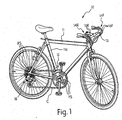
- Figure 1 is a side elevational view of a bicycle equipped with front and rear shifting systems in accordance with the present invention
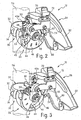
- Figure 2 is an enlarged rear perspective view of the front derailleur of the front shifting system illustrated in Figure 1 ; with the chain guide in a retracted position;
- Figure 3 is an enlarged rear perspective view of the front derailleur of the front shifting system illustrated in Figure 1 , with the chain guide in an extended position;
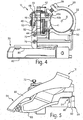
- Figure 4 is a top, plan view of the front derailleur illustrated in Figures 2-3 , with the chain guide in the retracted position;
- Figure 5 is an outside, elevational view of the front derailleur illustrated in Figures 2-4 ;
- Figure 6 is a rear elevational view of the front derailleur illustrated in Figures 2-5 , with the chain guide in the retracted position;
- Figure 7 is a rear elevational view of the front derailleur illustrated in Figures 2-5 , with the chain guide in an extended position;
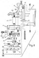
- Figure 8 is an exploded, (top, plan) view of the front derailleur illustrated in Figures 2-7 ;
- Figure 9 is an enlarged, top plan view of the first clamping portion of the fixing body of the front derailleur illustrated in Figures 2-8 ;
- Figure 10 is a rear end elevational view of the first clamping portion illustrated in Figure 9 ;
- Figure 11 is an opposite (front) end elevational view of the first clamping portion illustrated in Figures 9 and 10 ;
- Figure 12 is a bottom plan view of the first clamping portion illustrated in Figures 9-11 ;
- Figure 13 is an enlarged perspective view of the main mounting axle of the front derailleur positioning device of the front derailleur illustrated in Figures 2-8 ;
- Figure 14 is a side elevational view of the main mounting axle illustrated in Figure 13 ;
- Figure 15 is an end elevational view of the main mounting axle illustrated in Figures 13 and 14 ;
- Figure 16 is an end elevational view of the support member or housing member of the front derailleur positioning device of the front derailleur illustrated in Figures 2-8 ;
- Figure 17 is top, plan view of the support member illustrated in Figure 16 ;
- Figure 18 is a first side elevational view of the support member illustrated in Figures 16 and 17 ;
- Figure 19 is a second (opposite) side elevational view of the support member illustrated in Figures 16-18 ;
- Figure 20 is a top, plan view of the wire winding member of the front derailleur positioning device of the front derailleur illustrated in Figures 2-8 ;
- Figure 21 is an end elevational view of the wire winding member illustrated in Figure 20 ;
- Figure 22 is a bottom, plan view of the wire winding member illustrated in Figures 20 and 21 ;
- Figure 23 is a top, plan view of the engagement member of the front derailleur positioning device of the front derailleur illustrated in Figures 2-8 ;
- Figure 24 is an end elevational view of the engagement member illustrated in Figure 23 ;
- Figure 25 is an end elevational view of the positioning member of the front derailleur positioning device of the front derailleur illustrated in Figures 2-8 ;
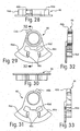
- Figure 26 is a top, plan view of the positioning member illustrated in Figure 25 ;
- Figure 27 is a side elevational view of the positioning member illustrated in Figures 26 and 27 ;
- Figure 28 is a top, plan view of the holding part of the front derailleur positioning device of the front derailleur illustrated in Figures 2-8 ;
- Figure 29 is a (first) end elevational view of the holding part illustrated in Figure 28 ;
- Figure 30 is bottom plan view of the holding part illustrated in Figures 28 and 29 ;
- Figure 31 is a (second) end elevational view of the holding part illustrated in Figures 28-30 ;
- Figure 32 is a cross-sectional view of the holding part illustrated in Figures 28-31 , as viewed along section line 32-32 of Figure 29 ;
- Figure 33 is a side elevational view of the holding part illustrated in Figures 28-32 ; ,
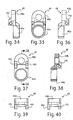
- Figure 34 is a (first) side elevational view of the linkage part of the front derailleur positioning device of the front derailleur illustrated in Figures 2-8 ;
- Figure 35 is a (first) end elevational view of the linkage part illustrated in Figure 34 ;
- Figure 36 is a (second) opposite side elevational view of the linkage part illustrated in Figures 34 and 35 ;
- Figure 37 is a (second) opposite end elevational view of the linkage part illustrated in Figures 34-36 ;
- Figure 38 is a cross-sectional view of the linkage part illustrated in Figures 34-37 , as viewed along section line 38-38 of Figure 37 ;
- Figure 39 is a bottom, plan view of the linkage part illustrated in Figures 34-38 ;
- Figure 40 is a top, plan view of the linkage part illustrated in Figures 34-39 ;
- Figure 41 is a partial, diagrammatic end elevational view of the front derailleur positioning device of the front derailleur illustrated in Figures 2-8 , with the operating member in a first operating position such that the positioning member is held in a first position in engagement with the engagement member;
- Figure 42 is a view of the front derailleur positioning device illustrated in Figure 41 , with the operating member moved to a first intermediate position from the first operating position such that the positioning member is no longer held in engagement with the engagement member;
- Figure 43 is a view of the front derailleur positioning device illustrated in Figures 41 and 42 , with the operating member moved to a second intermediate position from the first intermediate position illustrated in Figure 42 and with the positioning member moved to a second position out of engagement with the engagement member;
- Figure 44 is a view of the front derailleur positioning device illustrated in Figures 41-43 , with the operating member moved to a third intermediate position from the second intermediate position illustrated in Figure 43 such that the positioning member moves back into engagement with the engagement member;
- Figure 45 is a view of the front derailleur positioning device illustrated in Figures 41-44 , with the operating member moved to a second operating position from the third intermediate position illustrated in Figure 44 such that the positioning member is held in engagement with the engagement member;
- Figure 46 is a view of the front derailleur positioning device illustrated in Figures 41-45 , with the operating member in a third operating position such that the positioning member is held in engagement with the engagement member;
- Figure 47 is a view of the front derailleur positioning device illustrated in Figure 41-46 , with the operating member moved to a first intermediate position from the third operating position illustrated in Figure 46 such that the positioning member is no longer held in engagement with the engagement member;
- Figure 48 is a view of the front derailleur positioning device illustrated in Figures 41-47 , with the operating member moved to a second intermediate position from the first intermediate position illustrated in Figure 47 and with the positioning member moved to a second position out of engagement with the engagement member;
- Figure 49 is a view of the front derailleur positioning device illustrated in Figures 41-48 , with the operating member moved to the second operating position from the second intermediate position illustrated in Figure 48 (i.e. third intermediate position not shown) such that the positioning member back into engagement with the engagement member;
- Figure 50 is an enlarged, side elevational view of the rear derailleur of the rear shifting system illustrated in Figure 1 ;
- Figure 51 is an end elevational view of the engagement member of the rear derailleur positioning device of the rear, derailleur illustrated in Figure 1 and 50 ;
- Figure 52 is a top, plan view of the engagement member illustrated in Figure 51 ;
- Figure 53 is an enlarged, top plan view of the rear (left) shifter of the rear shifting system illustrated in Figure 1 ;
- Figure 54 is an enlarged; top plan view of the front (right) shifter of the rear shifting system illustrated in Figure 1 .
- the front shifting system includes front derailleur 12 and a front shifter 14F operatively coupled to the front derailleur 12 via a pair of front shift control cables 16F to move a chain C between at least two (three illustrated herein) front sprockets or chain rings FS.
- the rear shifting system includes a rear derailleur 18 and a rear shifter 14R operatively coupled to the rear derailleur 18 via a pair of rear shift control cables 16R to move the chain C between a plurality (e.g. seven or eight) of rear sprockets or chain rings RS.
- the front and rear deraille 12 and 18 are attached to the frame 11 of the bicycle 10, while the front and rear shifters 14F and 14R are attached to the handlebar 13.
- the handlebar 13 is fixedly coupled to the front fork, which is pivotally attached to the frame 11 to steer the bicycle 10 in a conventional manner.
- the front and rear shift control cables 16F and 16R are routed along the frame 11 between the front and rear shifters 14F and 14R, and the front and rear derailleurs 12 and 18, respectively.
- the pair of front shift cables 16F are conventional Bowden-type cables with each having an outer casing 16a and an inner wire 16b.
- the pair of rear shift control cables 16R are conventional Bowden-type cables with each having an outer casing 16a and an inner wire 16b.
- the bicycle 10 is conventional, except for the front and rear shifting systems. Accordingly, the bicycle 10. and its various components will not be discussed and/or illustrated in detail herein, except as related to the front and rear shifting systems of the present invention. Moreover, it will be apparent to those skilled in the bicycle art from this disclosure that various modifications can be made to the bicycle 10 and its components without departing from the present invention.
- the front derailleur 12 includes a fixing body or base member 20, a front derailleur (component) positioning device 22, a support link 24 and a chain guide 26 in accordance with the present invention.
- the fixing body 20 is fixedly attached to the seat tube 11a of the frame 11.
- the positioning device 22 is coupled between the fixing body 20 and the chain guide 26 to move the chain guide 26 between and retain the chain guide 26 in at least two shift positions (three illustrated herein) in accordance with the present invention, as best understood from Figures 1 , 6 and 7 .
- the support link 24 is pivotally coupled to the fixing body 20 and the chain guide 26.
- the chain guide 26 is not normally biased relative to the base member 20 toward any one of the shift positions by a biasing member. Actuation of the positioning device 22 of the front derailleur 12 is controlled by the front shifter 14F, which will be explained below.
- the front derailleur 12 is relatively conventional, except for the positioning device 22. Accordingly, the front derailleur 12 will not be explained and/or illustrated in detail herein, except as related to the positioning device 22 of the present invention.
- Portions of the fixing body 20, the positioning device 22, the support link 24 and the chain guide 26 constitute parts of a four bar linkage assembly that is relatively wide.
- the four bar linkage assembly is preferably defined by four pivot axes A, B, C and D as best seen in Figures 5 and 6 .
- a portion of the positioning device 22 defines a one link between the pivot axes A and B
- a portion of the support link 24 defines one link between the pivot axes C and D
- a portion of the chain guide 26 defines one link between the pivot axes B and D
- a portion of the fixing body 20 defines one link between the pivot axes A and C.
- the fixing body 20 is preferably a tubular clamping member or mechanism that is attached to the seat tube 11a of the bicycle frame 11.
- front derailleur 12 can be coupled to other parts of the bicycle 10 such as the bottom bracket as needed and/or desired.
- the chain guide 26 is movably supported relative to the fixing body 20 by the positioning device 22 and the support link 24 to move laterally relative to a longitudinal center plane P of the bicycle 10 between various shift positions (i.e., at least one retracted position and at least one extended position) that correspond to the positions of the front sprockets FS.
- the seat tube 11a preferably includes a center axis X that lies within the longitudinal plane P.
- the fixing body 20 is preferably located beneath the chain guide 26 (at least below the top portion of the chain guide 26 that is coupled to the positioning device 22 and the support link 24) in this embodiment.
- the fixing body 20 basically includes a first clamping portion 30, a second clamping portion 32, a pivot pin 34 and a fastener 36, as best seen in Figure 4 .
- First ends of clamping portions 30 and 32 are pivotally coupled together by the pivot pin 34, which extends in a substantially vertical direction relative to the bicycle 10 in a conventional manner.
- the other ends of clamping portions 30 and 32 are releasably connected together via the fastener 36.
- the first and second clamping portions 30 and 32 are constructed of a rigid material to non-movably secure the fixing body 20 of the front derailleur 12 to the seat tube 11a of the bicycle 10.
- the clamping portions 30 and 32 are constructed of metal utilizing conventional manufacturing techniques such as stamping/bending, casting and/or machining.
- the first clamping portion 30 supports the chain guide 26 via the positioning device 22 and the support link 24.
- the first clamping portion 30 has first and second threaded bores 30a and 30b which are configured to attach parts of the positioning device 22 therein, as explained below.
- the support link 24 is pivotally coupled to the first clamping portion 30 and the chain guide 26 using conventional pivot pins or the like in a conventional manner.
- the positioning device 22 includes a main mounting axle 40, a housing member or housing member 42, a cable winding member 44, a holding or retaining part 46, an operated or linkage part 48 and a positioning mechanism 50.
- the positioning mechanism 50 releasably retains the cable winding member 44, the retaining part 46 and the linkage part 48 in at least two operating positions (three illustrated herein) relative to the housing member 42 in accordance with the present invention.
- the main mounting axle 40 is fixed to the first clamping portion 30. Specifically, the main mounting axle 40 is threadedly attached in the mounting hole 30a of the first clamping portion 30.
- the housing member 42 is supported on the main mounting axle 40 and attached to the first clamping portion 30 via at least one additional fastener 41 such as a bolt attached in the hole 30b so that the housing member 42 is non-movably fixed to the first clamping portion 30 of the fixing body 20.
- the housing member 42, the main mounting axle 40 and the at least one additional fastener 41 constitute parts of a fixed member that is non-movably fixed to the fixing body 20 in accordance with the present invention, as best understood from Figure 8 .
- the wire winding member 44, the retaining part 46 and the linkage part 48 are all pivotally supported on the main mounting axle 40 for movement about the pivot axis A.
- the wire winding member 44, the retaining part 46 and the linkage part 48 are connected together to selectively move the chain guide 26 between the at least two (three illustrated herein) shift positions in response to movement of the front shift control cables 16F due to actuation of the front shifter 14F.
- the wire winding member 44, the retaining part 46 and the linkage part 48 are not rotationally biased relative to the fixed parts of the front derailleur 12 about the pivot axis A by a biasing member.
- the wire winding member 44, the retaining part 46 and the linkage part 48 constitute parts of an operating member that is movably coupled to the main mounting axle 40 and the housing member 42 to move between at least two operating positions (three illustrated herein) in accordance with the present invention, as explained below.
- the positioning mechanism 50 is operatively disposed between the housing member 42, the wire operating member 44 and the retaining part 46 to hold these parts in a number of operating positions (at least two) corresponding to the number of shift positions of the chain guide 26, as best understood from Figures 41-49 .
- the operated or linkage part 48 is pivotally coupled to the chain guide 26 to move the chain guide 26 between the various shift positions in response to movement of the wire operating member 44 and the retaining part 46 between the various operating positions.
- the linkage part 48 is attached to the retaining part 46 via an adjustment mechanism 52 such that the linkage part 48 and the retaining part 46 normally rotate together, yet relative rotational positions of the linkage part 48 and the retaining part 46 are adjustable, as explained below.
- the linkage part 46 pivots about the pivot axis A to move the chain guide 26.
- the main mounting axle 40 basically has an elongated rod-shaped configuration.
- the main mounting axle includes a threaded section 40a, a tool engagement section 40b, a support section 40c and a retaining section 40d that are preferably integrally formed together as a one-piece, unitary member from a light weight rigid material such as a metallic material using conventional manufacturing techniques such as casting and/or machining.
- the threaded section 40a is received in the threaded bore 30a of the first clamping portion.
- the tool engagement section 40b is used to rotate the main mounting axle during attachment to the first clamping portion 30, and also spaces the housing member 42 from the first clamping portion 30.
- the support section 40c pivotally supports the housing member 42, the wire operating member 44, the retaining part 46 and the linkage part 48.
- the housing member 42 is non-movable relative to the first clamping portion 30 due to the at least one fastener 41.
- an additional spacing washer is disposed on the at least one fastener 41 between the first clamping portion 30 and the housing member 42.
- the retaining section 40d has an annular groove, which receives a retaining clip or the like to retain the wire operating member 44, the retaining part 46 and the linkage part 48 on the support section 40c.
- the housing member 42 is basically a cup-shaped member with an open end for receiving the front shift cable 16F.
- the housing member includes a base plate 42a and a generally semi-annular wall 42b with an arc-shaped recess 42c formed therein.
- the base plate 42a and the generally semi-annular wall 42b with the arc-shaped recess 42c are preferably integrally formed together as a one-piece, unitary member from a light weight rigid material such as a metallic material using conventional manufacturing techniques such as casting and/or machining.
- the base plate 42a has holes formed therein for receiving the main mounting axle 40 and the at least one fastener 41.
- the generally semi-annular wall 42b extends in a direction parallel to the pivot axis A from the base plate 42a.
- the arc shaped recess 42c receives an arc-shaped engagement member 43 ( Figures 23 and 24 ), which releasably engages a part of the positioning mechanism 50.
- the engagement member 43 preferably includes a number of notches 43a corresponding to the desired number of operating portions of the positioning device 22.
- the notches 43a constitute a mating structure of the housing member 42 (fixed member).
- the engagement member 43 is preferably constructed of a lightweight, rigid material with a relatively low coefficient of friction such as a plastic material.
- the engagement member 43 is constructed as a one-piece member that is axially slid into the arc-shaped recess 42c.
- the wire operating member 44 basically has a disc-shaped (ring) configuration.
- the wire operating member 44 includes a main body portion 44a, a pair of actuating projections 44b, a cable attachment projection 44c, a hold/release part 44d and a pair of circumferential winding grooves 44e extending about the main body portion 44a.
- the main body portion 44a is mounted on the main pivot axle 40.
- the main body portion 44a, the pair of actuating projections 44b, the cable attachment projection 44c and the hold/release part 44d are preferably integrally formed together as a one-piece, unitary member from a light weight rigid material such as a metallic material using conventional manufacturing techniques such as casting and/or machining.
- the wire winding member 44 constitutes an input portion of the operating member.
- the actuating projections 44b and the hold release part 44d extend from one axial side of the body portion 44a, while the cable attachment projection 44c extends from the opposite axial side of the body portion 44.
- the cable attachment projection 44c has a threaded hole that receives a fastener 45a such as a bolt in order to attach an L-shaped cable attachment plate 45b to the cable attachment projection 44c.
- the L-shaped cable attachment plate 45b holds the inner wires 16b of the front shift cables 16F in the wire winding grooves 44e as best understood from Figures 2-4 and 8 .
- the outer peripheral surface of the body portion 44a has one flat side as seen in Figure 21 to facilitate clamping the front shift cables 16F thereto.
- the wire winding grooves 44e can be shallower along this flat side.
- the inner wires 16b extend in opposite circumferential directions from the L-shaped cable attachment plate 45b in the wire winding grooves 44e around the main body portion 44a and upwardly along the seat tube 11a, as seen in Figures 6 and 7 .
- the wire winding grooves 44e, the cable attachment projection 44c, the fastener 45a and the L-shaped plate 45b constitute parts of a cable attachment structure, which fixedly attaches the free ends of the inner wires 16b of the front shift cables 16F to the wire operating member 44.
- the front shifter 14F pulls one of the inner wires 16b of the front shift cables 16F, while the other of the inner wires 16b of the front shift cables 16F is released a corresponding amount by the front shifter 14F in order to rotate the wire operating member 44 back and forth about the pivot axis A.
- the actuating projections 44b are circumferentially spaced from each other about the pivot axis A.
- the actuating projections 44b are arranged and configured to contact the retaining part 46 after the wire operating member 44 moves a predetermined amount about the pivot axis A from the operating positions.
- the retaining part 46 rotates with the wire operating member 44 after the wire operating member 44 moves the predetermined amount about the pivot axis A from the operating positions.
- the wire operating member 44 is preferably movable back and forth in opposite rotational directions.
- the actuating projections 44b constitute parts of an actuating portion of the input portion of the positioning device 22 in accordance with the present invention.
- the hold/release part 44d of the wire operating member 44 disengages the positioning mechanism 50 when the wire operating member 44 is moved the predetermined amount about the pivot axis A from the operating positions, as explained below.
- the hold/release part 44d is preferably circumferentially equally spaced from the actuating projections 44b such that predetermined amount about the pivot axis A from the operating positions is the same in both rotational directions.
- the hold/release part 44d has an arc-shaped configuration with a pair of end projections 44f extending radially outwardly therefrom, and a blind bore 44g extending radially inwardly from an outer surface of the hold/release part 44d.
- the hold/release part is configured and arranged to selectively maintain/release the positioning mechanism 50 to prevent/allow rotation of the retaining part 46, as explained below.
- the retaining part 46 is a generally pie-shaped member, which includes a pair of oppositely facing circumferential abutment surfaces 46a, an adjustment protrusion 46b, a pair of arc-shaped slots 46c and a positioning recess 46d.
- the retaining part 46 is integrally formed as a one-piece, unitary member from a light weight rigid material such as a metallic material using conventional manufacturing techniques such as casting and/or machining.
- the actuating projections 44b of the wire operating member 44 selectively contact the abutment surfaces 46a such that the wire operating member 44 moves the retaining part 46 after a predetermined amount of relative rotation therebetween (i.e. in each rotational direction).
- the adjustment protrusion 46b contacts a pair of screws 53 that are attached to the linkage part 48.
- the adjustment protrusion 46b and the screws 53 constitute parts of the adjustment mechanism 52. Normally, the screws 53 are tightened so that the retaining part 46 and the linkage part 48 are not rotationally movable relative to each other. However, when the relative positions of the retaining part 46 and the linkage part 48 need to be adjusted, one of the screws 53 is loosened, and the other screw 53 is tightened a corresponding amount.
- the positioning recess 46d receives the hold/release part 44d therein with a pair of biasing elements (springs) 47 disposed on opposite circumferential sides of the hold/release 44d to normally maintain the retaining part 46 in a stationary intermediate position between two end positions of the limited rotational movement relative to the wire operating member 44, as seen in Figures 41 , 45 , 46 and 49 .
- the biasing elements 47 and the hold/release part 44d of the wire operating member 44 there is a limited amount of relative rotational movement permitted between the wire operating member 44 and the retaining part 46, as best understood from Figures 42-44 , 47 and 48 .
- Part of the positioning mechanism 50 is also received in the recess 46b and in the slots 46c, as explained below.
- the linkage part 48 basically includes a first end 48a, a second end 48b and a pair of adjustment flanges 48c.
- the linkage part 48 is integrally formed as a one-piece, unitary member from a light weight rigid material such as a metallic material using conventional manufacturing techniques such as casting and/or machining.
- the first end 48a is pivotally mounted on the main mounting axle 40.
- the second end 48b is pivotally attached to the chain guide 26 using a conventional pivot pin or pivot bolt.
- the adjustment protrusion 46b is disposed between the adjustment flanges 48c such that the screws 53 can be threadedly attached to the adjustment flanges 48c and contact the adjustment protrusion 46b.
- the retaining part 46 and the linkage part 48 constitute two parts of an output portion of the operating member.
- the adjustment flanges 48c together with the adjustment protrusion 46b and the screws 53 constitute parts of the adjustment mechanism 52 between the retaining part 46 and the linkage part 48.
- the positioning mechanism 50 basically includes a positioning member 54 as well as parts/portions of the wire operating member 44 (e.g. the hold/release part 44d), the retaining part 46 (e.g., the slots 46c and the positioning recess 46d) and the housing member 42 (e.g., the engagement member 43).
- the positioning member is an arc-shaped member, which includes a central engagement projection 54a, a central spring support projection 54b and a pair of pins 54c disposed at opposite ends thereof.
- the positioning member 54 is preferably constructed as a one-piece, unitary member from a light weight rigid material such as a metallic material using conventional manufacturing techniques such as casting and/or machining.
- the positioning member 54 is constructed of a material, which does not deform during use (i.e. a relatively inelastic, rigid material).
- the positioning member 54 is disposed within the positioning recess 46d of the retaining part together with the hold/release part 44d.
- the pins 54c of the positioning member 54 are received in the slots 46c to control movement of the positioning member 54.
- a radial biasing member 56 is mounted on the central spring support projection 54b and received in the blind bore 44g of the hold/release part 44d to normally bias the positioning member toward a first position in engagement with the engagement member 43.
- the pair of end projections44f hold (the pins 54c) positioning member 54 in the first position.
- the positioning member 54 can move to a second position disengaged from the engagement member 43.
- the positioning member 54 selectively pivots about one of the pins 54c such that the other pin 54c slides in its respective slot 46c when the positioning member 54 moves from the first position to the second position.
- Such movement of the positioning member 54 from the first position to the second position is illustrated in Figures 41-43 and 46-48 .
- the biasing elements 47 normally maintain the wire operating member 44 in a holding (intermediate) position to hold the positioning member 54 in engagement with a mating structure of the engagement member 43 when the wire operating member 44 is in each of the operating positions.
- the support link 24 includes a pair (front and rear) of link plates 60 and 62 with a connecting portion 64 extending between the link plates 60 and 62.
- the support link 24 is preferably constructed of a hard rigid material.
- the support link is preferably constructed of metal utilizing conventional manufacturing techniques such as stamping/beriding, casting and/or machining.
- the link plates 60 and 62 are substantially vertical plates, while the connecting portion 64 extends in a longitudinal direction relative to the bicycle 10.
- the link plates 60 and 62 are pivotally coupled to the first clamping portion 30 of the fixing body 20 via conventional pivot pins or the like in a conventional manner.
- the link plates 60 and 62 are also pivotally coupled to the chain guide 26 via conventional pivot pins or the like in a conventional manner, in order to pivotally support the chain guide 26.
- the link plate 60 is provided with a fan-shaped end that selectively engages adjustment screws 70 and 72 for limiting movement of chain guide 26 in its extended most position and its retracted most position, respectively, in a conventional manner.
- the adjustment screws 70 and 72 are threadedly attached to the chain guide 26.
- the adjustment screw 70 is a high adjustment screw that limits outward movement of the chain guide 26 in its (top) extended most position
- the adjustment screw 72 is a low adjustment screw that limits inward movement of the chain guide 26 in its (low) retracted most position.
- the chain guide 26 includes an inner guide plate 80 and an outer guide plate 82 rigidly connected to the inner guide plate 80 in a spaced arrangement to form a chain receiving area therebetween.
- Each of the guide plates 80 and 82 is preferably constructed of a hard rigid material.
- each of the guide plates 80 and 82 of the chain guide 26 is preferably constructed of metal such as a rigid sheet metal that is bent to the desired shape.
- the inner and outer guide plates 80 and 82 are preferably connected together at the front of the chain guide 26 and at the rear of the chain guide 26.
- the inner guide plate 80 is pivotally coupled to the positioning device 22 (i.e. the linkage part 48) using the pivot pin or pivot bolt, and pivotally coupled to the link plates 60 and 62 of the support link 24.
- the rear derailleur 18 includes a fixing body or base member 120, a rear derailleur (component) positioning device 122, a pair of links 124 and a movable member 126 supporting a rear chain guide 128 in accordance with the present invention.
- the fixing body 120 is fixedly attached to the rear triangle of the frame 11 in a conventional manner.
- the links 124 are pivotally coupled between the base member 120 and the movable member 126 to form a four bar linkage in a conventional manner.
- the positioning device 122 has a pivot axis that is common to one of the pivot axes of the links 124 at the base member 120 and is coupled to the link 124 having a common pivot axis therewith.
- the positioning device 122 will rotate one of the links 124 in response to pulling and releasing the inner wires 16b of the rear shift cables 16R to move the movable member 126 and chain guide 128 laterally over the rear sprockets RS.
- the movable member 126 and chain guide 128 are not normally biased relative to the base member 120 toward any one of the shift positions by a biasing member. Actuation of the positioning device 122 of the rear derailleur 18 is controlled by the rear shifter 14R, which will be explained below.
- the rear derailleur 18 is relatively conventional, except for the positioning device 122. Accordingly, the rear derailleur 18 will not be explained and/or illustrated in detail herein, except as related to the positioning device 122 of the present invention. Moreover, the positioning device 122 is identical to the positioning device 22 of the front derailleur 12, except the positioning device 122 utilizes a modified engagement member 143 in place of the engagement member 43 of the positioning device 22. Accordingly, the positioning device 122 will not be discussed and/or illustrated in detail herein. However, it will be apparent to those skilled in the art from this disclosure that the descriptions and illustrations of the positioning device 22 also apply to the positioning device 122, except as explained and/or illustrated herein. Furthermore, it will be apparent to those skilled in the art from this disclosure that parts of the positioning device 122 that are identical to the positioning mechanism 22 can be identified with identical reference numerals for the sake of convenience.
- the engagement member 143 is identical to the engagement member 43 of the front derailleur 12, except for the number of operating (shift) positions has been increased to accommodate the increased number of rear sprockets RS. Thus, the engagement member 143 has more notches 143a than the engagement member 43.
- the rear derailleur chain guide 128 is operatively coupled to the positioning device 122 such that when parts of the positioning device 122 are moved between the various operating positions in a manner similar to the first embodiment, the linkage part 48 of the positioning device 122 will move the links 124 about their pivot axes on the base member 120 to move the chain guide 128 between an extended position and a retracted position. Movement of the chain guide 128 caused by movement of the links 124 is well known in the art, and thus, will not be explained and/or illustrated in further detail herein for the sake of brevity.
- the front shifter 14F includes a fixing body 220F, a front positioning device 222F, and a shift lever SL.
- the rear shifter 14R includes a fixing body 220R, a rear positioning device 222R, and a shift lever SL.
- the front and rear shifters 14F and 14R are identical to each other, except that they are mirror images of each other, and utilize the engagement members 43 and 143 in the positioning devices 222F and 222R, respectively.
- the positioning device 222F is identical to the positioning device 22, except the linkage part 48 of the positioning device 22 has been eliminated and the shift lever SL has been added.
- the positioning device 222R is identical to the positioning device 122, except the linkage part 48 of the positioning device 122 has been eliminated and the shift lever SL has been added.
- the shift levers SL are arranged to move the wire operating members 44 of the front and rear positioning devices 222F and 222R.
- the positioning devices 222F and 222R will not be discussed and/or illustrated in detail herein. However, it will be apparent to those skilled in the art from this disclosure that the descriptions and illustrations of the positioning devices 22 and 122 also apply to the positioning devices 222F and 222R, respectively, except as explained and/or illustrated herein. Furthermore, it will be apparent to those skilled in the art from this disclosure that parts of the positioning devices 222F and 222R that are identical to the positioning devices 22 and 122, respectively, can be identified with identical reference numerals for the sake of convenience. In any event, the shift control levers SL are operatively coupled to the wire operating members 44 in order to move the wire operating members 44 from the operating positions in response to rider actuation of the shift control levers SL.
- the term “comprising” and its derivatives, as used herein, are intended to he open ended terms that specify the presence of the stated features, elements, components, groups, integers, and/or steps, but do not exclude the presence of other unstated features, elements, components, groups, integers and/or steps.
- the foregoing also applies to words having similar meanings such as the terms, “including”, “having” and their derivatives.
- the terms "part,” “section,” “portion,” “member” or “element” when used in the singular can have the dual meaning of a single part or a plurality of parts.
Landscapes
- Engineering & Computer Science (AREA)
- Chemical & Material Sciences (AREA)
- Combustion & Propulsion (AREA)
- Transportation (AREA)
- Mechanical Engineering (AREA)
- Flexible Shafts (AREA)
- Transmission Devices (AREA)
- Gear-Shifting Mechanisms (AREA)
- Mechanical Control Devices (AREA)
Abstract
Description
- This invention generally relates to a bicycle component positioning device. More specifically, the present invention relates to a bicycle component positioning device for a bicycle component such as a derailleur or shifter, which has the same relatively easy action when moved in two opposite directions, yet is reliably retained.
- Bicycling is becoming an increasingly more popular form of recreation as well as a means of transportation. Moreover, bicycling has become a very popular competitive sport for both amateurs and professionawls. Whether the bicycle is used for recreation, transportation or competition, the bicycle industry is constantly improving the various components of the bicycle such as derailleurs and shifters.
- A bicycle derailleur basically includes a base, a chain guide and a linkage coupled between the base and the chain guide to move the chain guide between various shift positions. The base is fixed to the bicycle frame. A spring is arranged to bias the chain guide in one lateral direction relative to the base. A control cable is used to move the chain guide against the biasing force of the spring when pulled, and to allow the bias force of the spring to move the chain guide in an opposite direction when the cable is released. A shifter is attached to the cable to selectively pull/release the cable to move the chain guide laterally back and forth respectively. With these conventional derailleurs, shifting is not always as smooth and reliable as desired by some riders. Moreover, the control cable is always held in tension by the spring, which leads to continued cable stretching. Continued cable stretching leads to frequent adjustment of the derailleur and/or shifter or minor misalignment of the derailleur. Furthermore, conventional derailleurs can be relatively complicated and expensive to manufacture, assemble, to mount to the bicycle and/or adjust.
- The shifter for controlling conventional derailleurs typically utilize one or more levers coupled to a winding member to selectively pull/release the cable. The winding member is retained in various shift positions by a retaining structure, friction or the like. Optionally, some shifters further include an indexing mechanism with a plurality of positions corresponding to the number of shift positions. In any case, a sufficient retaining force must be applied to the winding member to prevent undesired movement of the chain guide of the derailleur due to the biasing force of the derailleur spring. Thus, a relatively strong retaining force must be provided, which can be relatively difficult to overcome when moving the lever(s). Additionally, when the shifting device is actuated to wind the cable, an even stronger force is often required than during an unwinding operating due to the derailleur biasing member. In either case, the shifting action(s) may feel awkward to some individuals. Also, with these conventional shifters, shifting is not always as smooth and reliable as desired by some riders. Moreover, conventional shifters can be relatively complicated and expensive to manufacture, assemble, to mount to the bicycle and/or adjust.
- In view of the above, it will be apparent to those skilled in the art from this disclosure that there exists a need for an improved bicycle component positioning device. This invention addresses this need in the art as well as other needs, which will become apparent to those skilled in the art from this disclosure.
- One object of the present invention is to provide a bicycle component positioning device, which moves smoothly and reliably, yet is reliably retained in different positions.
- Another object of the present invention is to provide a bicycle component positioning device, which has a similar relatively light action when moved in opposite directions.
- Another object of the present invention is to provide a bicycle component positioning device, which is relatively simple and inexpensive to manufacture and/or assemble.
- The foregoing objects can basically be attained by providing a bicycle component positioning device, which comprises a fixed member, an operating member and a positioning mechanism. The operating member is movably coupled to the fixed member to move between at least two operating positions. The operating member has an input portion and an output portion. The positioning mechanism is operatively disposed between the operating member and the fixed member. The positioning mechanism includes a positioning member that is movable between a first position in which the positioning member is engaged with the fixed member and a second position in which the positioning member is disengaged from the fixed member. The positioning member is held in engagement with the fixed member in the first position by the input portion when the input portion is in at least one of the operating positions. The positioning member is movable from the first position to the second position upon movement of the input portion from at least one of the operating positions.
- These and other objects, features, aspects and advantages of the present invention will become apparent to those skilled in the art from the following detailed description, which, taken in conjunction with the annexed drawings, discloses preferred embodiments of the present invention.
- Referring now to the attached drawings which form a part of this original disclosure:
-
Figure 1 is a side elevational view of a bicycle equipped with front and rear shifting systems in accordance with the present invention; -
Figure 2 is an enlarged rear perspective view of the front derailleur of the front shifting system illustrated inFigure 1 ; with the chain guide in a retracted position; -
Figure 3 is an enlarged rear perspective view of the front derailleur of the front shifting system illustrated inFigure 1 , with the chain guide in an extended position; -
Figure 4 is a top, plan view of the front derailleur illustrated inFigures 2-3 , with the chain guide in the retracted position; -
Figure 5 is an outside, elevational view of the front derailleur illustrated inFigures 2-4 ; -
Figure 6 is a rear elevational view of the front derailleur illustrated inFigures 2-5 , with the chain guide in the retracted position; -
Figure 7 is a rear elevational view of the front derailleur illustrated inFigures 2-5 , with the chain guide in an extended position; -
Figure 8 is an exploded, (top, plan) view of the front derailleur illustrated inFigures 2-7 ; -
Figure 9 is an enlarged, top plan view of the first clamping portion of the fixing body of the front derailleur illustrated inFigures 2-8 ; -
Figure 10 is a rear end elevational view of the first clamping portion illustrated inFigure 9 ; -
Figure 11 is an opposite (front) end elevational view of the first clamping portion illustrated inFigures 9 and 10 ; -
Figure 12 is a bottom plan view of the first clamping portion illustrated inFigures 9-11 ; -
Figure 13 is an enlarged perspective view of the main mounting axle of the front derailleur positioning device of the front derailleur illustrated inFigures 2-8 ; -
Figure 14 is a side elevational view of the main mounting axle illustrated inFigure 13 ; -
Figure 15 is an end elevational view of the main mounting axle illustrated inFigures 13 and 14 ; -
Figure 16 is an end elevational view of the support member or housing member of the front derailleur positioning device of the front derailleur illustrated inFigures 2-8 ; -
Figure 17 is top, plan view of the support member illustrated inFigure 16 ; -
Figure 18 is a first side elevational view of the support member illustrated inFigures 16 and 17 ; -
Figure 19 is a second (opposite) side elevational view of the support member illustrated inFigures 16-18 ; -
Figure 20 is a top, plan view of the wire winding member of the front derailleur positioning device of the front derailleur illustrated inFigures 2-8 ; -
Figure 21 is an end elevational view of the wire winding member illustrated inFigure 20 ; -
Figure 22 is a bottom, plan view of the wire winding member illustrated inFigures 20 and 21 ; -
Figure 23 is a top, plan view of the engagement member of the front derailleur positioning device of the front derailleur illustrated inFigures 2-8 ; -
Figure 24 is an end elevational view of the engagement member illustrated inFigure 23 ; -
Figure 25 is an end elevational view of the positioning member of the front derailleur positioning device of the front derailleur illustrated inFigures 2-8 ; -
Figure 26 is a top, plan view of the positioning member illustrated inFigure 25 ; -
Figure 27 is a side elevational view of the positioning member illustrated inFigures 26 and 27 ; -
Figure 28 is a top, plan view of the holding part of the front derailleur positioning device of the front derailleur illustrated inFigures 2-8 ; -
Figure 29 is a (first) end elevational view of the holding part illustrated inFigure 28 ; -
Figure 30 is bottom plan view of the holding part illustrated inFigures 28 and 29 ; -
Figure 31 is a (second) end elevational view of the holding part illustrated inFigures 28-30 ; -
Figure 32 is a cross-sectional view of the holding part illustrated inFigures 28-31 , as viewed along section line 32-32 ofFigure 29 ; -
Figure 33 is a side elevational view of the holding part illustrated inFigures 28-32 ; , -
Figure 34 is a (first) side elevational view of the linkage part of the front derailleur positioning device of the front derailleur illustrated inFigures 2-8 ; -
Figure 35 is a (first) end elevational view of the linkage part illustrated inFigure 34 ; -
Figure 36 is a (second) opposite side elevational view of the linkage part illustrated inFigures 34 and 35 ; -
Figure 37 is a (second) opposite end elevational view of the linkage part illustrated inFigures 34-36 ; -
Figure 38 is a cross-sectional view of the linkage part illustrated inFigures 34-37 , as viewed along section line 38-38 ofFigure 37 ; -
Figure 39 is a bottom, plan view of the linkage part illustrated inFigures 34-38 ; -
Figure 40 is a top, plan view of the linkage part illustrated inFigures 34-39 ; -
Figure 41 is a partial, diagrammatic end elevational view of the front derailleur positioning device of the front derailleur illustrated inFigures 2-8 , with the operating member in a first operating position such that the positioning member is held in a first position in engagement with the engagement member; -
Figure 42 is a view of the front derailleur positioning device illustrated inFigure 41 , with the operating member moved to a first intermediate position from the first operating position such that the positioning member is no longer held in engagement with the engagement member; -
Figure 43 is a view of the front derailleur positioning device illustrated inFigures 41 and 42 , with the operating member moved to a second intermediate position from the first intermediate position illustrated inFigure 42 and with the positioning member moved to a second position out of engagement with the engagement member; -
Figure 44 is a view of the front derailleur positioning device illustrated inFigures 41-43 , with the operating member moved to a third intermediate position from the second intermediate position illustrated inFigure 43 such that the positioning member moves back into engagement with the engagement member; -
Figure 45 is a view of the front derailleur positioning device illustrated inFigures 41-44 , with the operating member moved to a second operating position from the third intermediate position illustrated inFigure 44 such that the positioning member is held in engagement with the engagement member; -
Figure 46 is a view of the front derailleur positioning device illustrated inFigures 41-45 , with the operating member in a third operating position such that the positioning member is held in engagement with the engagement member; -
Figure 47 is a view of the front derailleur positioning device illustrated inFigure 41-46 , with the operating member moved to a first intermediate position from the third operating position illustrated inFigure 46 such that the positioning member is no longer held in engagement with the engagement member; -
Figure 48 is a view of the front derailleur positioning device illustrated inFigures 41-47 , with the operating member moved to a second intermediate position from the first intermediate position illustrated inFigure 47 and with the positioning member moved to a second position out of engagement with the engagement member; -
Figure 49 is a view of the front derailleur positioning device illustrated inFigures 41-48 , with the operating member moved to the second operating position from the second intermediate position illustrated inFigure 48 (i.e. third intermediate position not shown) such that the positioning member back into engagement with the engagement member; -
Figure 50 is an enlarged, side elevational view of the rear derailleur of the rear shifting system illustrated inFigure 1 ; -
Figure 51 is an end elevational view of the engagement member of the rear derailleur positioning device of the rear, derailleur illustrated inFigure 1 and50 ; -
Figure 52 is a top, plan view of the engagement member illustrated inFigure 51 ; -
Figure 53 is an enlarged, top plan view of the rear (left) shifter of the rear shifting system illustrated inFigure 1 ; and -
Figure 54 is an enlarged; top plan view of the front (right) shifter of the rear shifting system illustrated inFigure 1 . - Selected embodiments of the present invention will now be explained with reference to the drawings. It will be apparent to those skilled in the art from this disclosure that the following descriptions of the embodiments of the present invention are provided for illustration only and not for the purpose of limiting the invention as defined by the appended claims and their equivalents.
- Referring initially to
Figures 1-3 , abicycle 10 is illustrated with a front shifting system and a rear shifting system coupled thereto in accordance with the present invention. The front shifting system includesfront derailleur 12 and afront shifter 14F operatively coupled to thefront derailleur 12 via a pair of frontshift control cables 16F to move a chain C between at least two (three illustrated herein) front sprockets or chain rings FS. Similarly, the rear shifting system includes arear derailleur 18 and arear shifter 14R operatively coupled to therear derailleur 18 via a pair of rearshift control cables 16R to move the chain C between a plurality (e.g. seven or eight) of rear sprockets or chain rings RS. - The front and
rear derailleurs frame 11 of thebicycle 10, while the front andrear shifters handlebar 13. Thehandlebar 13 is fixedly coupled to the front fork, which is pivotally attached to theframe 11 to steer thebicycle 10 in a conventional manner. The front and rearshift control cables frame 11 between the front andrear shifters rear derailleurs front shift cables 16F are conventional Bowden-type cables with each having an outer casing 16a and aninner wire 16b. Similarly; the pair of rearshift control cables 16R are conventional Bowden-type cables with each having an outer casing 16a and aninner wire 16b. - The
bicycle 10 is conventional, except for the front and rear shifting systems. Accordingly, thebicycle 10. and its various components will not be discussed and/or illustrated in detail herein, except as related to the front and rear shifting systems of the present invention. Moreover, it will be apparent to those skilled in the bicycle art from this disclosure that various modifications can be made to thebicycle 10 and its components without departing from the present invention. - Referring initially to
Figures 1-8 , thefront derailleur 12 of the front shifting system in accordance with the present invention will now be explained in more detail. Thefront derailleur 12 includes a fixing body orbase member 20, a front derailleur (component)positioning device 22, asupport link 24 and achain guide 26 in accordance with the present invention. The fixingbody 20 is fixedly attached to theseat tube 11a of theframe 11. Thepositioning device 22 is coupled between the fixingbody 20 and thechain guide 26 to move thechain guide 26 between and retain thechain guide 26 in at least two shift positions (three illustrated herein) in accordance with the present invention, as best understood fromFigures 1 ,6 and7 . Thesupport link 24 is pivotally coupled to the fixingbody 20 and thechain guide 26. Thechain guide 26 is not normally biased relative to thebase member 20 toward any one of the shift positions by a biasing member. Actuation of thepositioning device 22 of thefront derailleur 12 is controlled by thefront shifter 14F, which will be explained below. - The
front derailleur 12 is relatively conventional, except for thepositioning device 22. Accordingly, thefront derailleur 12 will not be explained and/or illustrated in detail herein, except as related to thepositioning device 22 of the present invention. Portions of the fixingbody 20, thepositioning device 22, thesupport link 24 and thechain guide 26 constitute parts of a four bar linkage assembly that is relatively wide. The four bar linkage assembly is preferably defined by four pivot axes A, B, C and D as best seen inFigures 5 and6 . A portion of thepositioning device 22 defines a one link between the pivot axes A and B, a portion of thesupport link 24 defines one link between the pivot axes C and D, a portion of thechain guide 26 defines one link between the pivot axes B and D, and a portion of the fixingbody 20 defines one link between the pivot axes A and C. - Referring to
Figures 2-12 , the fixingbody 20 will now be discussed in more detail. The fixingbody 20 is preferably a tubular clamping member or mechanism that is attached to theseat tube 11a of thebicycle frame 11. However, it will be apparent to those skilled in the art from this disclosure thatfront derailleur 12 can be coupled to other parts of thebicycle 10 such as the bottom bracket as needed and/or desired. In any event, thechain guide 26 is movably supported relative to the fixingbody 20 by thepositioning device 22 and thesupport link 24 to move laterally relative to a longitudinal center plane P of thebicycle 10 between various shift positions (i.e., at least one retracted position and at least one extended position) that correspond to the positions of the front sprockets FS. Theseat tube 11a preferably includes a center axis X that lies within the longitudinal plane P. - The fixing
body 20 is preferably located beneath the chain guide 26 (at least below the top portion of thechain guide 26 that is coupled to thepositioning device 22 and the support link 24) in this embodiment. The fixingbody 20 basically includes afirst clamping portion 30, asecond clamping portion 32, apivot pin 34 and afastener 36, as best seen inFigure 4 . First ends of clampingportions pivot pin 34, which extends in a substantially vertical direction relative to thebicycle 10 in a conventional manner. The other ends of clampingportions fastener 36. The first andsecond clamping portions body 20 of thefront derailleur 12 to theseat tube 11a of thebicycle 10. Preferably, the clampingportions - The
first clamping portion 30 supports thechain guide 26 via thepositioning device 22 and thesupport link 24. Specifically, thefirst clamping portion 30 has first and second threadedbores positioning device 22 therein, as explained below. Thesupport link 24 is pivotally coupled to thefirst clamping portion 30 and thechain guide 26 using conventional pivot pins or the like in a conventional manner. - Referring now to
Figures 2-49 , thepositioning device 22 in accordance with the present invention will now be explained. Thepositioning device 22 includes a main mountingaxle 40, a housing member orhousing member 42, acable winding member 44, a holding or retainingpart 46, an operated orlinkage part 48 and apositioning mechanism 50. Thepositioning mechanism 50 releasably retains thecable winding member 44, the retainingpart 46 and thelinkage part 48 in at least two operating positions (three illustrated herein) relative to thehousing member 42 in accordance with the present invention. - The main mounting
axle 40 is fixed to thefirst clamping portion 30. Specifically, the main mountingaxle 40 is threadedly attached in the mountinghole 30a of thefirst clamping portion 30. Thehousing member 42 is supported on the main mountingaxle 40 and attached to thefirst clamping portion 30 via at least oneadditional fastener 41 such as a bolt attached in thehole 30b so that thehousing member 42 is non-movably fixed to thefirst clamping portion 30 of the fixingbody 20. Thus, thehousing member 42, the main mountingaxle 40 and the at least oneadditional fastener 41 constitute parts of a fixed member that is non-movably fixed to the fixingbody 20 in accordance with the present invention, as best understood fromFigure 8 . - The
wire winding member 44, the retainingpart 46 and thelinkage part 48 are all pivotally supported on the main mountingaxle 40 for movement about the pivot axis A. Thewire winding member 44, the retainingpart 46 and thelinkage part 48 are connected together to selectively move thechain guide 26 between the at least two (three illustrated herein) shift positions in response to movement of the frontshift control cables 16F due to actuation of thefront shifter 14F. Thewire winding member 44, the retainingpart 46 and thelinkage part 48 are not rotationally biased relative to the fixed parts of thefront derailleur 12 about the pivot axis A by a biasing member. Thus, thewire winding member 44, the retainingpart 46 and thelinkage part 48 constitute parts of an operating member that is movably coupled to the main mountingaxle 40 and thehousing member 42 to move between at least two operating positions (three illustrated herein) in accordance with the present invention, as explained below. - The
positioning mechanism 50 is operatively disposed between thehousing member 42, thewire operating member 44 and the retainingpart 46 to hold these parts in a number of operating positions (at least two) corresponding to the number of shift positions of thechain guide 26, as best understood fromFigures 41-49 . The operated orlinkage part 48 is pivotally coupled to thechain guide 26 to move thechain guide 26 between the various shift positions in response to movement of thewire operating member 44 and the retainingpart 46 between the various operating positions. Specifically, thelinkage part 48 is attached to the retainingpart 46 via anadjustment mechanism 52 such that thelinkage part 48 and the retainingpart 46 normally rotate together, yet relative rotational positions of thelinkage part 48 and the retainingpart 46 are adjustable, as explained below. Thus, when the retainingpart 46 is rotated by thewire operating member 44, thelinkage part 46 pivots about the pivot axis A to move thechain guide 26. - Referring to
Figures 2-8 and13-15 , the main mountingaxle 40 will now be explained in more detail. The main mountingaxle 40 basically has an elongated rod-shaped configuration. The main mounting axle includes a threadedsection 40a, atool engagement section 40b, asupport section 40c and aretaining section 40d that are preferably integrally formed together as a one-piece, unitary member from a light weight rigid material such as a metallic material using conventional manufacturing techniques such as casting and/or machining. - The threaded
section 40a is received in the threadedbore 30a of the first clamping portion. Thetool engagement section 40b is used to rotate the main mounting axle during attachment to thefirst clamping portion 30, and also spaces thehousing member 42 from thefirst clamping portion 30. Thesupport section 40c pivotally supports thehousing member 42, thewire operating member 44, the retainingpart 46 and thelinkage part 48. However, thehousing member 42 is non-movable relative to thefirst clamping portion 30 due to the at least onefastener 41. Preferably, an additional spacing washer is disposed on the at least onefastener 41 between thefirst clamping portion 30 and thehousing member 42. The retainingsection 40d has an annular groove, which receives a retaining clip or the like to retain thewire operating member 44, the retainingpart 46 and thelinkage part 48 on thesupport section 40c. - Referring to
Figures 2-8 ,16-19, 23 and 24 , thehousing member 42 will now be explained in more detail. Thehousing member 42 is basically a cup-shaped member with an open end for receiving thefront shift cable 16F. The housing member includes abase plate 42a and a generallysemi-annular wall 42b with an arc-shapedrecess 42c formed therein. Thebase plate 42a and the generallysemi-annular wall 42b with the arc-shapedrecess 42c are preferably integrally formed together as a one-piece, unitary member from a light weight rigid material such as a metallic material using conventional manufacturing techniques such as casting and/or machining. - The
base plate 42a has holes formed therein for receiving the main mountingaxle 40 and the at least onefastener 41. The generallysemi-annular wall 42b extends in a direction parallel to the pivot axis A from thebase plate 42a. The arc shapedrecess 42c receives an arc-shaped engagement member 43 (Figures 23 and 24 ), which releasably engages a part of thepositioning mechanism 50. Specifically, theengagement member 43 preferably includes a number ofnotches 43a corresponding to the desired number of operating portions of thepositioning device 22. Thenotches 43a constitute a mating structure of the housing member 42 (fixed member). Theengagement member 43 is preferably constructed of a lightweight, rigid material with a relatively low coefficient of friction such as a plastic material. In this embodiment, theengagement member 43 is constructed as a one-piece member that is axially slid into the arc-shapedrecess 42c. - Referring to
Figures 2-8 and20-22 , thewire operating member 44 will now be explained in more detail. Thewire operating member 44 basically has a disc-shaped (ring) configuration. Thewire operating member 44 includes amain body portion 44a, a pair of actuatingprojections 44b, acable attachment projection 44c, a hold/release part 44d and a pair ofcircumferential winding grooves 44e extending about themain body portion 44a. Themain body portion 44a is mounted on themain pivot axle 40. Preferably, themain body portion 44a, the pair of actuatingprojections 44b, thecable attachment projection 44c and the hold/release part 44d are preferably integrally formed together as a one-piece, unitary member from a light weight rigid material such as a metallic material using conventional manufacturing techniques such as casting and/or machining. Thewire winding member 44 constitutes an input portion of the operating member. - The actuating
projections 44b and thehold release part 44d extend from one axial side of thebody portion 44a, while thecable attachment projection 44c extends from the opposite axial side of thebody portion 44. Thecable attachment projection 44c has a threaded hole that receives afastener 45a such as a bolt in order to attach an L-shapedcable attachment plate 45b to thecable attachment projection 44c. The L-shapedcable attachment plate 45b holds theinner wires 16b of thefront shift cables 16F in thewire winding grooves 44e as best understood fromFigures 2-4 and8 . The outer peripheral surface of thebody portion 44a has one flat side as seen inFigure 21 to facilitate clamping thefront shift cables 16F thereto. Thewire winding grooves 44e can be shallower along this flat side. - The
inner wires 16b extend in opposite circumferential directions from the L-shapedcable attachment plate 45b in thewire winding grooves 44e around themain body portion 44a and upwardly along theseat tube 11a, as seen inFigures 6 and7 . Thewire winding grooves 44e, thecable attachment projection 44c, thefastener 45a and the L-shapedplate 45b constitute parts of a cable attachment structure, which fixedly attaches the free ends of theinner wires 16b of thefront shift cables 16F to thewire operating member 44. Thefront shifter 14F pulls one of theinner wires 16b of thefront shift cables 16F, while the other of theinner wires 16b of thefront shift cables 16F is released a corresponding amount by thefront shifter 14F in order to rotate thewire operating member 44 back and forth about the pivot axis A. - The actuating
projections 44b are circumferentially spaced from each other about the pivot axis A. The actuatingprojections 44b are arranged and configured to contact the retainingpart 46 after thewire operating member 44 moves a predetermined amount about the pivot axis A from the operating positions. The retainingpart 46 rotates with thewire operating member 44 after thewire operating member 44 moves the predetermined amount about the pivot axis A from the operating positions. Thewire operating member 44 is preferably movable back and forth in opposite rotational directions. The actuatingprojections 44b constitute parts of an actuating portion of the input portion of thepositioning device 22 in accordance with the present invention. - The hold/
release part 44d of thewire operating member 44 disengages thepositioning mechanism 50 when thewire operating member 44 is moved the predetermined amount about the pivot axis A from the operating positions, as explained below. The hold/release part 44d is preferably circumferentially equally spaced from the actuatingprojections 44b such that predetermined amount about the pivot axis A from the operating positions is the same in both rotational directions. The hold/release part 44d has an arc-shaped configuration with a pair ofend projections 44f extending radially outwardly therefrom, and ablind bore 44g extending radially inwardly from an outer surface of the hold/release part 44d. The hold/release part is configured and arranged to selectively maintain/release thepositioning mechanism 50 to prevent/allow rotation of the retainingpart 46, as explained below. - Referring now to
Figures 2-8 and28-33 , the retainingpart 46 will now be explained in more detail. The retainingpart 46 is a generally pie-shaped member, which includes a pair of oppositely facingcircumferential abutment surfaces 46a, anadjustment protrusion 46b, a pair of arc-shapedslots 46c and apositioning recess 46d. Preferably, the retainingpart 46 is integrally formed as a one-piece, unitary member from a light weight rigid material such as a metallic material using conventional manufacturing techniques such as casting and/or machining. - The actuating
projections 44b of thewire operating member 44 selectively contact the abutment surfaces 46a such that thewire operating member 44 moves the retainingpart 46 after a predetermined amount of relative rotation therebetween (i.e. in each rotational direction). Theadjustment protrusion 46b contacts a pair ofscrews 53 that are attached to thelinkage part 48. Thus, the relative rotational positions of the retainingpart 46 and thelinkage part 48 can be adjusted by rotating thescrews 53. Theadjustment protrusion 46b and thescrews 53 constitute parts of theadjustment mechanism 52. Normally, thescrews 53 are tightened so that the retainingpart 46 and thelinkage part 48 are not rotationally movable relative to each other. However, when the relative positions of the retainingpart 46 and thelinkage part 48 need to be adjusted, one of thescrews 53 is loosened, and theother screw 53 is tightened a corresponding amount. - The
positioning recess 46d receives the hold/release part 44d therein with a pair of biasing elements (springs) 47 disposed on opposite circumferential sides of the hold/release 44d to normally maintain the retainingpart 46 in a stationary intermediate position between two end positions of the limited rotational movement relative to thewire operating member 44, as seen inFigures 41 ,45 ,46 and49 . However, due to the configuration of therecess 46b, the biasingelements 47 and the hold/release part 44d of thewire operating member 44, there is a limited amount of relative rotational movement permitted between thewire operating member 44 and the retainingpart 46, as best understood fromFigures 42-44 ,47 and 48 . Part of thepositioning mechanism 50 is also received in therecess 46b and in theslots 46c, as explained below. - Referring now to
Figures 2-8 and34-40 , thelinkage part 48 will now be explained in more detail. Thelinkage part 48 basically includes afirst end 48a, asecond end 48b and a pair ofadjustment flanges 48c. Preferably, thelinkage part 48 is integrally formed as a one-piece, unitary member from a light weight rigid material such as a metallic material using conventional manufacturing techniques such as casting and/or machining. Thefirst end 48a is pivotally mounted on the main mountingaxle 40. Thesecond end 48b is pivotally attached to thechain guide 26 using a conventional pivot pin or pivot bolt. - The
adjustment protrusion 46b is disposed between theadjustment flanges 48c such that thescrews 53 can be threadedly attached to theadjustment flanges 48c and contact theadjustment protrusion 46b. Thus, when the retainingpart 46 rotates about the pivot axis A, thelinkage part 48 rotates about the pivot axis A to move thechain guide 26. The retainingpart 46 and thelinkage part 48 constitute two parts of an output portion of the operating member. Theadjustment flanges 48c together with theadjustment protrusion 46b and thescrews 53 constitute parts of theadjustment mechanism 52 between the retainingpart 46 and thelinkage part 48. - Referring to
Figures 25-27 , thepositioning mechanism 50 will now be explained in more detail. Thepositioning mechanism 50 basically includes a positioningmember 54 as well as parts/portions of the wire operating member 44 (e.g. the hold/release part 44d), the retaining part 46 (e.g., theslots 46c and thepositioning recess 46d) and the housing member 42 (e.g., the engagement member 43). The positioning member is an arc-shaped member, which includes acentral engagement projection 54a, a centralspring support projection 54b and a pair ofpins 54c disposed at opposite ends thereof. The positioningmember 54 is preferably constructed as a one-piece, unitary member from a light weight rigid material such as a metallic material using conventional manufacturing techniques such as casting and/or machining. Preferably, the positioningmember 54 is constructed of a material, which does not deform during use (i.e. a relatively inelastic, rigid material). - Referring to
Figures 2-49 , the positioningmember 54 is disposed within thepositioning recess 46d of the retaining part together with the hold/release part 44d. Thepins 54c of the positioningmember 54 are received in theslots 46c to control movement of the positioningmember 54. Aradial biasing member 56 is mounted on the centralspring support projection 54b and received in theblind bore 44g of the hold/release part 44d to normally bias the positioning member toward a first position in engagement with theengagement member 43. Moreover, when thewire operating member 44 is in one of the operating positions, the pair of end projections44f hold (thepins 54c) positioningmember 54 in the first position. - However, when the
wire operating member 44 pivots a predetermined amount relative to the retainingpart 46, only one of thepins 54c is held, while theother pin 54c is movable in itsrespective slot 46c. Thus, when this occurs, the positioningmember 54 can move to a second position disengaged from theengagement member 43. In other words, the positioningmember 54 selectively pivots about one of thepins 54c such that theother pin 54c slides in itsrespective slot 46c when the positioningmember 54 moves from the first position to the second position. Such movement of the positioningmember 54 from the first position to the second position is illustrated inFigures 41-43 and46-48 . In other words, the biasingelements 47 normally maintain thewire operating member 44 in a holding (intermediate) position to hold the positioningmember 54 in engagement with a mating structure of theengagement member 43 when thewire operating member 44 is in each of the operating positions. - Referring again to
Figures 2-8 , thesupport link 24 includes a pair (front and rear) oflink plates portion 64 extending between thelink plates support link 24 is preferably constructed of a hard rigid material. For example, the support link is preferably constructed of metal utilizing conventional manufacturing techniques such as stamping/beriding, casting and/or machining. When thefront derailleur 12 is assembled, thelink plates portion 64 extends in a longitudinal direction relative to thebicycle 10. - The
link plates first clamping portion 30 of the fixingbody 20 via conventional pivot pins or the like in a conventional manner. Thelink plates chain guide 26 via conventional pivot pins or the like in a conventional manner, in order to pivotally support thechain guide 26. Thelink plate 60 is provided with a fan-shaped end that selectively engages adjustment screws 70 and 72 for limiting movement ofchain guide 26 in its extended most position and its retracted most position, respectively, in a conventional manner. The adjustment screws 70 and 72 are threadedly attached to thechain guide 26. Thus, theadjustment screw 70 is a high adjustment screw that limits outward movement of thechain guide 26 in its (top) extended most position, while theadjustment screw 72 is a low adjustment screw that limits inward movement of thechain guide 26 in its (low) retracted most position. - Referring still to
Figures 2-8 , thechain guide 26 includes aninner guide plate 80 and anouter guide plate 82 rigidly connected to theinner guide plate 80 in a spaced arrangement to form a chain receiving area therebetween. Each of theguide plates guide plates chain guide 26 is preferably constructed of metal such as a rigid sheet metal that is bent to the desired shape. The inner andouter guide plates chain guide 26 and at the rear of thechain guide 26. Theinner guide plate 80 is pivotally coupled to the positioning device 22 (i.e. the linkage part 48) using the pivot pin or pivot bolt, and pivotally coupled to thelink plates support link 24. - Referring now to
Figures 50-52 , therear derailleur 18 of the rear shifting system in accordance with the present invention will now be explained in more detail. Therear derailleur 18 includes a fixing body orbase member 120, a rear derailleur (component)positioning device 122, a pair oflinks 124 and amovable member 126 supporting arear chain guide 128 in accordance with the present invention. The fixingbody 120 is fixedly attached to the rear triangle of theframe 11 in a conventional manner. Thelinks 124 are pivotally coupled between thebase member 120 and themovable member 126 to form a four bar linkage in a conventional manner. Thepositioning device 122 has a pivot axis that is common to one of the pivot axes of thelinks 124 at thebase member 120 and is coupled to thelink 124 having a common pivot axis therewith. Thus, thepositioning device 122 will rotate one of thelinks 124 in response to pulling and releasing theinner wires 16b of therear shift cables 16R to move themovable member 126 andchain guide 128 laterally over the rear sprockets RS. Themovable member 126 andchain guide 128 are not normally biased relative to thebase member 120 toward any one of the shift positions by a biasing member. Actuation of thepositioning device 122 of therear derailleur 18 is controlled by therear shifter 14R, which will be explained below. - The
rear derailleur 18 is relatively conventional, except for thepositioning device 122. Accordingly, therear derailleur 18 will not be explained and/or illustrated in detail herein, except as related to thepositioning device 122 of the present invention. Moreover, thepositioning device 122 is identical to thepositioning device 22 of thefront derailleur 12, except thepositioning device 122 utilizes a modifiedengagement member 143 in place of theengagement member 43 of thepositioning device 22. Accordingly, thepositioning device 122 will not be discussed and/or illustrated in detail herein. However, it will be apparent to those skilled in the art from this disclosure that the descriptions and illustrations of thepositioning device 22 also apply to thepositioning device 122, except as explained and/or illustrated herein. Furthermore, it will be apparent to those skilled in the art from this disclosure that parts of thepositioning device 122 that are identical to thepositioning mechanism 22 can be identified with identical reference numerals for the sake of convenience. - The
engagement member 143 is identical to theengagement member 43 of thefront derailleur 12, except for the number of operating (shift) positions has been increased to accommodate the increased number of rear sprockets RS. Thus, theengagement member 143 hasmore notches 143a than theengagement member 43. In any case, the rearderailleur chain guide 128 is operatively coupled to thepositioning device 122 such that when parts of thepositioning device 122 are moved between the various operating positions in a manner similar to the first embodiment, thelinkage part 48 of thepositioning device 122 will move thelinks 124 about their pivot axes on thebase member 120 to move thechain guide 128 between an extended position and a retracted position. Movement of thechain guide 128 caused by movement of thelinks 124 is well known in the art, and thus, will not be explained and/or illustrated in further detail herein for the sake of brevity. - Referring now to
Figures 53 and 54 , the front andrear shifters front shifter 14F includes a fixingbody 220F, afront positioning device 222F, and a shift lever SL. Similarly, Therear shifter 14R includes a fixingbody 220R, arear positioning device 222R, and a shift lever SL. The front andrear shifters engagement members positioning devices positioning device 222F is identical to thepositioning device 22, except thelinkage part 48 of thepositioning device 22 has been eliminated and the shift lever SL has been added. Similarly, thepositioning device 222R is identical to thepositioning device 122, except thelinkage part 48 of thepositioning device 122 has been eliminated and the shift lever SL has been added. The shift levers SL are arranged to move thewire operating members 44 of the front andrear positioning devices - In view of the similarities between the
positioning devices positioning devices positioning devices positioning devices positioning devices positioning devices positioning devices wire operating members 44 in order to move thewire operating members 44 from the operating positions in response to rider actuation of the shift control levers SL. - In understanding the scope of the present invention, the term "comprising" and its derivatives, as used herein, are intended to he open ended terms that specify the presence of the stated features, elements, components, groups, integers, and/or steps, but do not exclude the presence of other unstated features, elements, components, groups, integers and/or steps. The foregoing also applies to words having similar meanings such as the terms, "including", "having" and their derivatives. Also, the terms "part," "section," "portion," "member" or "element" when used in the singular can have the dual meaning of a single part or a plurality of parts. As used herein to describe the present invention, the following directional terms "forward, rearward, above, downward, vertical, horizontal, below and transverse" as well as any other similar directional terms refer to those directions of a bicycle equipped with the present invention. Accordingly, these terms, as utilized to describe the present invention should be interpreted relative to a bicycle equipped with the present invention as used in the normal riding position. Finally, terms of degree such as "substantially", "about" and "approximately" as used herein mean a reasonable amount of deviation of the modified term such that the end result is not significantly changed.
- While only selected embodiments have been chosen to illustrate the present invention, it will be apparent to those skilled in the art from this disclosure that various changes and modifications can be made herein without departing from the scope of the invention as defined in the appended claims. Furthermore, the foregoing descriptions of the embodiments according to the present invention are provided for illustration only, and not for the purpose of limiting the invention as defined by the appended claims and their equivalents.
Claims (19)
- A bicycle component positioning device comprising:a fixed member;an operating member movably coupled to the fixed member to move between at least two operating positions, the operating member having an input portion and an output portion; anda positioning mechanism operatively disposed between the operating member and the fixed member, the positioning mechanism including a positioning member that is movable between a first position in which the positioning member is engaged with the fixed member and a second position in which the positioning member is disengaged from the fixed member,the positioning member being held in engagement with the fixed member in the first position by the input portion when the input portion is in at least one of the operating positions, andthe positioning member being movable from the first position to the second position upon movement of the input portion from at least one of the operating positions.
- The bicycle component positioning device according to claim 1, wherein
the operating member is pivotally coupled to the fixed member about a pivot axis, in particular the operating member being not rotationally biased about the pivot axis relative to the fixed member by a biasing member. - The bicycle component positioning device according to claim 2, wherein
the input portion of the operating member includes an actuating portion configured and arranged to move the output portion of the operating member after the input portion moves a predetermined amount about the pivot axis from at least one of the operating positions. - The bicycle component positioning device according to claim 3, wherein
the actuating portion includes a pair of circumferentially spaced actuating abutments that selectively contact the output portion after the input portion moves the predetermined amount about the pivot axis from the operating position. - The bicycle component positioning device according to any one of the proceeding claims 1 to 4, wherein
the output portion of the operating member includes a first part that is attached to a second part using an adjustment mechanism in order to adjust the relative positions of the first and second parts. - The bicycle component positioning device according to any one of the proceeding claims 1 to 5, wherein
the input portion and the output portion are coupled together such that there is a limited amount of relative rotational movement therebetween - The bicycle component positioning device according to any one of the proceeding claims 1 to 6, wherein
the operating member includes at least one element disposed between the output portion and the input portion to maintain the output portion in a stationary intermediate position between two end positions of a/the limited rotational movement. - The bicycle component positioning device according to any one of the proceeding claims 1 to 7, wherein
the operating member includes a pair of biasing elements arranged on circumferentially opposite sides of the input portion, in particular the biasing elements normally maintain the input portion in an intermediate position to hold the positioning member in engagement with a mating structure of the fixed member when the input portion is in each of the operating positions. - The bicycle component positioning device according to any one of the proceeding claims 1 to 8, wherein
the positioning member is normally biased toward the first position by a biasing element disposed between the positioning member and the input portion. - The bicycle component positioning device according to any one of the proceeding claims 1 to 9, wherein
the positioning member is movably supported by the output portion to move between the first position and the second position. - The bicycle component positioning device according to any one of the proceeding claims 1 to 10, wherein
the positioning member has an arc-shaped configuration with a central projection extending therefrom to selectively engage a mating structure of the fixed member. - The bicycle component positioning device according to any one of the proceeding claims 1 to 11, wherein
the positioning member includes a pin disposed at each end of the positioning member with each pin being received in a respective slot of the output portion, in particular the positioning member selectively pivots about one of the pins such that the other pin slides in its respective slot when the positioning member moves from the first position to the second position. - The bicycle component positioning device according to any one of the proceeding claims 1 to 12, wherein
the positioning member includes at least one projection disposed in a slot of the output portion to control movement of the positioning member between the first position and the second position. - The bicycle component positioning device according to any one of the proceeding claims 1 to 13, wherein
one of the input portion and the output portion includes a cable attachment structure configured and arranged to attach at least one control cable thereto. - The bicycle component positioning device according to claim 14, wherein
the one of the input portion and the output portion having the cable attachment structure includes a first wire winding groove extending in a first circumferential direction away from the cable attachment structure and a second wire winding groove extending in a second circumferential direction away from the cable attachment structure that is opposite to the first circumferential direction. - The bicycle component positioning device according to any one of the proceeding claims 1 to 15, wherein
the positioning member is made of rigid material. - The bicycle component positioning device according to any one of the proceeding claims 1 to 16, further comprising
a shift control lever operatively coupled to the operating member in order to move the input portion from the operating position in response to rider actuation of the shift control lever. - The bicycle component positioning device according to any one of the proceeding claims 1 to 17, further comprising
a front derailleur chain guide operatively coupled to the operating member to move between an extended position and a retracted position in response to movement of operating member between the two operating positions. - The bicycle component positioning device according to any one of the proceeding claims 1 to 17, further comprising
a rear derailleur chain guide operatively coupled to the operating member to move between an extended position and a retracted position in response to movement of operating member between the two operating positions.
Applications Claiming Priority (1)
| Application Number | Priority Date | Filing Date | Title |
|---|---|---|---|
| US11/672,673 US8777788B2 (en) | 2007-02-08 | 2007-02-08 | Bicycle component positioning device |
Publications (3)
| Publication Number | Publication Date |
|---|---|
| EP1955940A2 true EP1955940A2 (en) | 2008-08-13 |
| EP1955940A3 EP1955940A3 (en) | 2009-04-29 |
| EP1955940B1 EP1955940B1 (en) | 2012-02-15 |
Family
ID=39429284
Family Applications (1)
| Application Number | Title | Priority Date | Filing Date |
|---|---|---|---|
| EP07020887A Not-in-force EP1955940B1 (en) | 2007-02-08 | 2007-10-25 | Bicycle component positioning device |
Country Status (5)
| Country | Link |
|---|---|
| US (1) | US8777788B2 (en) |
| EP (1) | EP1955940B1 (en) |
| JP (1) | JP2008195381A (en) |
| CN (1) | CN101239644A (en) |
| TW (1) | TWI346633B (en) |
Cited By (1)
| Publication number | Priority date | Publication date | Assignee | Title |
|---|---|---|---|---|
| EP2428441A1 (en) * | 2010-09-09 | 2012-03-14 | Chang Hui Lin | Derailleur |
Families Citing this family (17)
| Publication number | Priority date | Publication date | Assignee | Title |
|---|---|---|---|---|
| US9156524B2 (en) * | 2013-09-30 | 2015-10-13 | Shimano Inc. | Derailleur |
| US9248885B2 (en) * | 2013-09-30 | 2016-02-02 | Shimano Inc. | Derailleur |
| ITMI20131641A1 (en) * | 2013-10-04 | 2015-04-05 | Campagnolo Srl | LATERAL MOVEMENT STOP DEVICE FOR A BICYCLE CHAIN |
| US9469378B2 (en) * | 2014-09-17 | 2016-10-18 | Shimano Inc. | Bicycle derailleur |
| US9434448B2 (en) * | 2014-10-31 | 2016-09-06 | Shimano Inc. | Bicycle derailleur |
| US9616970B2 (en) * | 2015-07-03 | 2017-04-11 | Shimano Inc. | Bicycle derailleur |
| US10005513B2 (en) | 2015-07-06 | 2018-06-26 | Shimano Inc. | Bicycle operating device |
| DE102015010311A1 (en) * | 2015-08-06 | 2017-02-09 | Sram Deutschland Gmbh | Front derailleur device for a bicycle chain transmission |
| US10689060B2 (en) | 2015-10-08 | 2020-06-23 | Shimano Inc. | Bicycle operating device |
| US9714067B1 (en) * | 2016-02-29 | 2017-07-25 | Shimano Inc. | Bicycle chain device |
| US10086905B2 (en) * | 2016-03-22 | 2018-10-02 | Shimano Inc. | Bicycle front derailleur with mounting bracket |
| US10207768B2 (en) | 2016-03-29 | 2019-02-19 | Shimano Inc. | Bicycle operating device |
| US10252773B2 (en) * | 2016-04-05 | 2019-04-09 | Shimano Inc. | Bicycle front derailleur |
| US10407128B2 (en) * | 2016-09-30 | 2019-09-10 | Shimano Inc. | Bicycle derailleur |
| IT201700015324A1 (en) * | 2017-02-13 | 2018-08-13 | Campagnolo Srl | Front derailleur for bicycle |
| DE102018214218A1 (en) * | 2018-08-22 | 2020-02-27 | Sram Deutschland Gmbh | Rear wheel derailleur with eccentric cable pulley arrangement with gear ratio |
| EP4008622B1 (en) * | 2020-12-03 | 2024-09-04 | SRAM Deutschland GmbH | Rear derailleur for coaxial connection to a bicycle frame |
Family Cites Families (76)
| Publication number | Priority date | Publication date | Assignee | Title |
|---|---|---|---|---|
| US2431513A (en) * | 1944-10-21 | 1947-11-25 | Frank W Schwinn | Chain shifting device for bicycles and the like |
| GB602711A (en) | 1945-11-10 | 1948-06-01 | Louis Camillis | Improvements in hand-lever and bowden-wire control mechanism for sprocket-gear changing on cycles |
| US3481217A (en) * | 1967-12-15 | 1969-12-02 | Tetsuo Maeda | Gear shift lever |
| FR2154018A5 (en) | 1971-09-16 | 1973-05-04 | Mathauser William | |
| US3890847A (en) * | 1974-04-12 | 1975-06-24 | Beatrice Foods Co | Front derailler for bicycles |
| JPS5143541A (en) | 1974-10-12 | 1976-04-14 | Shimano Industrial Co | Gaisohensokukino kirikaesochi |
| JPS5128934A (en) | 1974-09-06 | 1976-03-11 | Shimano Industrial Co | GAISOHEN SOKUKI |
| JPS5150141A (en) | 1974-10-23 | 1976-05-01 | Shimano Industrial Co | GAISOHEN SOKUKI |
| JPS5118046A (en) | 1974-08-06 | 1976-02-13 | Shimano Industrial Co | GAISOHEN SOKUKI |
| JPS5215033A (en) | 1975-07-24 | 1977-02-04 | Bridgestone Cycle Ind Co | External transmission for bicycle |
| FR2342887A2 (en) | 1976-03-01 | 1977-09-30 | Juy Lucien | Gear change mechanism for bicycles - has parallelogram linkage fitted to rear wheel hub with register mechanism |
| DE2654426A1 (en) * | 1975-12-02 | 1977-06-23 | Simplex Ets | GEAR SHIFTING FOR BICYCLES OR SIMILAR VEHICLES |
| JPS5286639A (en) | 1976-01-12 | 1977-07-19 | Shimano Industrial Co | External transmission |
| FR2345340A1 (en) * | 1976-03-23 | 1977-10-21 | Juy Lucien | SPEED CHANGE CONTROL LEVERS FOR CYCLES AND SIMILAR VEHICLES |
| JPS52133634A (en) * | 1976-04-30 | 1977-11-09 | Shimano Industrial Co | Delayer for bicycle |
| JPS5398644A (en) | 1977-02-04 | 1978-08-29 | Shimano Industrial Co | Derailer for bicycle |
| JPS5415241A (en) | 1977-07-01 | 1979-02-05 | Shimano Industrial Co | Derailer for bicycle |
| JPS5457738A (en) * | 1977-10-14 | 1979-05-09 | Maeda Ind | Operating lever device of sheath transmission for bicycle |
| DE2834646A1 (en) | 1978-08-08 | 1980-02-21 | Fichtel & Sachs Ag | CHAIN GEAR WITH GEAR PRESET |
| GB2099961B (en) | 1978-10-06 | 1983-05-25 | Shimano Industrial Co | Control lever for a cycle |
| JPH0649379B2 (en) * | 1984-10-26 | 1994-06-29 | キヤノン株式会社 | Information input / output device |
| JPH0246467Y2 (en) | 1984-12-14 | 1990-12-07 | ||
| JPS63119196A (en) * | 1986-11-07 | 1988-05-23 | 松下電器産業株式会社 | Thin film el panel |
| US5222412A (en) * | 1988-07-29 | 1993-06-29 | Shimano Industrial Co., Ltd. | Change speed lever apparatus for use in bicycle |
| US5012692A (en) * | 1988-09-24 | 1991-05-07 | Shimano Industrial Company Limited | Change-speed lever apparatus for use in bicycle |
| US5044213A (en) * | 1988-11-29 | 1991-09-03 | Shimano Industrial Co., Ltd. | Speed control apparatus for a bicycle |
| JP2848842B2 (en) * | 1989-04-11 | 1999-01-20 | 株式会社シマノ | Gear lever for bicycle |
| US5102372A (en) | 1991-03-20 | 1992-04-07 | Sram Corporation | Bicycle derailleur cable actuating system |
| JPH0828338A (en) | 1994-07-11 | 1996-01-30 | Unisia Jecs Corp | Crank angle position detection device and control device for internal combustion engine |
| US5666859A (en) * | 1994-12-02 | 1997-09-16 | Fichtel & Sachs Ag | Latching shifter for a bicycle transmission |
| EP0759393B1 (en) * | 1995-03-13 | 2002-08-21 | Sakae Co., Ltd. | Bicycle and speed change operating device for the same |
| US5588331A (en) | 1995-03-21 | 1996-12-31 | Industrial Technology Research Institute | Rotary shifter for bicycle |
| US5799542A (en) * | 1995-10-11 | 1998-09-01 | Shimano, Inc. | Bicycle shift control device |
| US5730030A (en) * | 1996-01-19 | 1998-03-24 | Shimano, Inc. | Shifting apparatus for bicycles having a brake operating unit disposed between first and second shifting levers |
| TW378183B (en) * | 1996-02-14 | 2000-01-01 | Shimano Kk | Bicycle shift levers which surround a handlebar |
| DE19613575A1 (en) | 1996-04-04 | 1997-10-09 | Fichtel & Sachs Ag | Catch switch for bicycle transmission |
| JP3678496B2 (en) * | 1996-05-30 | 2005-08-03 | 株式会社シマノ | Bicycle shifting operation device |
| US6066057A (en) | 1996-08-28 | 2000-05-23 | Shimano, Inc. | Gas actuated derailleur having an indexing mechanism for setting a chain guide in a plurality of fixed positions |
| DE19734685A1 (en) * | 1997-08-11 | 1999-02-18 | Sram De Gmbh | Latch switch, in particular twist grip switch for controlling a bicycle transmission |
| JP3996984B2 (en) | 1997-09-08 | 2007-10-24 | 株式会社シマノ | Bicycle shift mode selector switch |
| US6021688A (en) * | 1998-09-25 | 2000-02-08 | Chang; Wen-Pin | Twist handlebar for controlling the derailleur of a bicyle |
| US6135906A (en) | 1999-03-11 | 2000-10-24 | Shimano, Inc. | Gas actuating device with an exhaust passage that prevents contamination of an actuating member |
| US6467368B1 (en) * | 1999-08-03 | 2002-10-22 | National Science Council Of Republic Of China | Hand operated bicycle gear transmission device |
| DE19951700A1 (en) | 1999-10-27 | 2001-05-03 | Helmig Hans Gmbh | Actuator for bicycle gears with two-train system |
| DE10002741B4 (en) | 2000-01-22 | 2014-07-24 | Sram Deutschland Gmbh | Trigger switch for bicycle transmission |
| US6209413B1 (en) * | 2000-01-27 | 2001-04-03 | Wen-Pin Chang | Shifter for operating derailleur cable of a bicycle derailleur mechanism |
| US6390481B1 (en) | 2000-03-10 | 2002-05-21 | Power Tool Holders Incorporated | Locking chuck |
| TW448900U (en) * | 2000-05-04 | 2001-08-01 | Nat Science Council | Handle for bicycle gear change |
| US20020112559A1 (en) | 2001-02-22 | 2002-08-22 | Liu Jen-Chih | Manual shift mechanism of a bicycle |
| US6497163B2 (en) | 2001-04-04 | 2002-12-24 | Falcon Industrial Co., Ltd. | Dual dial rods speed changing controller capable of linear displacement |
| JP3501781B2 (en) | 2001-08-01 | 2004-03-02 | 株式会社シマノ | Bicycle transmission positioning device |
| US6862948B1 (en) | 2001-10-18 | 2005-03-08 | John L. Calendrille, Jr. | Shifter for a bicycle using a dual action lever which moves in the same motion as the natural movement of the thumb |
| US6923740B2 (en) * | 2001-11-26 | 2005-08-02 | Shimano Inc. | Front derailleur for a bicycle |
| US7150205B2 (en) * | 2002-04-04 | 2006-12-19 | Shimano, Inc. | Handgrip shifter for a bicycle |
| US8069749B2 (en) * | 2002-07-05 | 2011-12-06 | Shimano, Inc. | Shift control device for a bicycle transmission |
| JP2004061849A (en) * | 2002-07-29 | 2004-02-26 | Toshiba Corp | Liquid crystal display and manufacturing method thereof |
| TW532361U (en) | 2002-08-08 | 2003-05-11 | Ad Ii Engineering Inc | Derailleur operating apparatus for bicycle |
| US20040069089A1 (en) | 2002-10-15 | 2004-04-15 | Po-Cheng Chen | Handle mounted bicycles derailleur controller |
| US7125497B1 (en) * | 2003-05-22 | 2006-10-24 | Sandia Corporation | Reactive formulations for a neutralization of toxic industrial chemicals |
| TWM243593U (en) * | 2003-06-27 | 2004-09-11 | Bing-He Feng | Gearshift controlling apparatus for bicycle |
| US7290462B2 (en) * | 2003-08-11 | 2007-11-06 | Shimano, Inc. | Bicycle twist-grip shift control device with parallel gearing |
| DE602004008211T2 (en) | 2004-02-06 | 2007-12-20 | Campagnolo S.R.L. | Operating device for control cable of a bicycle transmission |
| FR2867903B1 (en) | 2004-03-22 | 2008-10-03 | Commissariat Energie Atomique | SOLID ELECTROLYTE FUEL CELL WITH SEALED STRUCTURE |
| DE602004006749T2 (en) | 2004-08-31 | 2007-10-04 | Campagnolo S.R.L. | Actuation device for control cable of a bicycle transmission, with rotatable support body for the cable drum |
| DE102004051883B4 (en) | 2004-10-26 | 2020-09-10 | Sram Deutschland Gmbh | Switch mechanism for a step switch for bicycles |
| US7340975B2 (en) * | 2004-12-21 | 2008-03-11 | Shimano, Inc. | Bicycle control apparatus with a position setting idler member |
| US7779718B2 (en) | 2005-03-03 | 2010-08-24 | Sram, Llc | Bicycle shifter |
| US7650813B2 (en) * | 2005-05-19 | 2010-01-26 | Shimano Inc. | Position control mechanism for bicycle control device |
| US7526979B2 (en) * | 2005-07-19 | 2009-05-05 | Shimano Inc. | Bicycle shift position control mechanism |
| FR2891770B1 (en) | 2005-10-06 | 2007-12-07 | Michelin Soc Tech | METHOD AND DEVICE FOR INFLATION PRESSURE MEASUREMENT OF A TIRE BY MEANS OF A STRAIN SENSOR |
| JP5150141B2 (en) | 2007-06-11 | 2013-02-20 | 株式会社東芝 | Fuel cell catalyst material, membrane electrode assembly using fuel cell catalyst material, and fuel cell using membrane electrode assembly |
| JP5143541B2 (en) | 2007-12-19 | 2013-02-13 | 株式会社トプコン | Ball shape measuring device |
| JP5525693B2 (en) | 2008-02-25 | 2014-06-18 | 株式会社東芝 | Ultrasonic diagnostic apparatus and control program for ultrasonic diagnostic apparatus |
| JP5215033B2 (en) | 2008-05-09 | 2013-06-19 | 大陽日酸株式会社 | Vapor growth method |
| JP5415241B2 (en) | 2009-12-04 | 2014-02-12 | 憲峰 大倉 | Support hardware |
| JP5398644B2 (en) | 2010-06-07 | 2014-01-29 | 株式会社東芝 | Light source device using semiconductor light emitting device |
-
2007
- 2007-02-08 US US11/672,673 patent/US8777788B2/en not_active Expired - Fee Related
- 2007-07-13 TW TW096125725A patent/TWI346633B/en not_active IP Right Cessation
- 2007-08-30 CN CNA2007101471401A patent/CN101239644A/en active Pending
- 2007-10-25 EP EP07020887A patent/EP1955940B1/en not_active Not-in-force
-
2008
- 2008-01-18 JP JP2008008885A patent/JP2008195381A/en active Pending
Non-Patent Citations (1)
| Title |
|---|
| None |
Cited By (1)
| Publication number | Priority date | Publication date | Assignee | Title |
|---|---|---|---|---|
| EP2428441A1 (en) * | 2010-09-09 | 2012-03-14 | Chang Hui Lin | Derailleur |
Also Published As
| Publication number | Publication date |
|---|---|
| TWI346633B (en) | 2011-08-11 |
| US8777788B2 (en) | 2014-07-15 |
| CN101239644A (en) | 2008-08-13 |
| EP1955940B1 (en) | 2012-02-15 |
| EP1955940A3 (en) | 2009-04-29 |
| US20080190234A1 (en) | 2008-08-14 |
| TW200833554A (en) | 2008-08-16 |
| JP2008195381A (en) | 2008-08-28 |
Similar Documents
| Publication | Publication Date | Title |
|---|---|---|
| EP1955940B1 (en) | Bicycle component positioning device | |
| EP1808367B1 (en) | Bicycle control device | |
| EP1897796B1 (en) | Bicycle rear derailleur | |
| EP1902936B1 (en) | Bicycle rear derailleur | |
| EP1985532B2 (en) | Bicycle component positioning device | |
| EP2653372B1 (en) | Bicycle chain guide | |
| EP1650121B1 (en) | Position control mechanism for bicycle control device | |
| EP1935774B1 (en) | Bicycle rear derailleur | |
| EP1902937B1 (en) | Bicycle rear derailleur | |
| CN111469976B (en) | Bicycle operating device | |
| EP1728714B1 (en) | Bicycle control device | |
| EP1747985A2 (en) | Bicycle rear derailleur | |
| EP1650123B1 (en) | Shift and brake control device | |
| EP2374704B1 (en) | Bicycle Shift Operating Device | |
| CN108528625B (en) | Bicycle operating device | |
| CN108528626B (en) | Bicycle operating device | |
| EP1746021B1 (en) | Bicycle rear derailleur | |
| US9937977B2 (en) | Bicycle operating system, take-up device, and bicycle operating apparatus | |
| US20080051237A1 (en) | Bicycle rear derailleur | |
| EP1790563B1 (en) | Bicycle front derailleur with angle adjustment | |
| EP1982912B1 (en) | Bicycle component positioning device |
Legal Events
| Date | Code | Title | Description |
|---|---|---|---|
| PUAI | Public reference made under article 153(3) epc to a published international application that has entered the european phase |
Free format text: ORIGINAL CODE: 0009012 |
|
| AK | Designated contracting states |
Kind code of ref document: A2 Designated state(s): AT BE BG CH CY CZ DE DK EE ES FI FR GB GR HU IE IS IT LI LT LU LV MC MT NL PL PT RO SE SI SK TR |
|
| AX | Request for extension of the european patent |
Extension state: AL BA HR MK RS |
|
| PUAL | Search report despatched |
Free format text: ORIGINAL CODE: 0009013 |
|
| AK | Designated contracting states |
Kind code of ref document: A3 Designated state(s): AT BE BG CH CY CZ DE DK EE ES FI FR GB GR HU IE IS IT LI LT LU LV MC MT NL PL PT RO SE SI SK TR |
|
| AX | Request for extension of the european patent |
Extension state: AL BA HR MK RS |
|
| 17P | Request for examination filed |
Effective date: 20091029 |
|
| AKX | Designation fees paid |
Designated state(s): DE FR IT |
|
| 17Q | First examination report despatched |
Effective date: 20091229 |
|
| GRAP | Despatch of communication of intention to grant a patent |
Free format text: ORIGINAL CODE: EPIDOSNIGR1 |
|
| GRAS | Grant fee paid |
Free format text: ORIGINAL CODE: EPIDOSNIGR3 |
|
| GRAA | (expected) grant |
Free format text: ORIGINAL CODE: 0009210 |
|
| AK | Designated contracting states |
Kind code of ref document: B1 Designated state(s): DE FR IT |
|
| REG | Reference to a national code |
Ref country code: DE Ref legal event code: R096 Ref document number: 602007020667 Country of ref document: DE Effective date: 20120412 |
|
| PLBE | No opposition filed within time limit |
Free format text: ORIGINAL CODE: 0009261 |
|
| STAA | Information on the status of an ep patent application or granted ep patent |
Free format text: STATUS: NO OPPOSITION FILED WITHIN TIME LIMIT |
|
| 26N | No opposition filed |
Effective date: 20121116 |
|
| PGFP | Annual fee paid to national office [announced via postgrant information from national office to epo] |
Ref country code: IT Payment date: 20121024 Year of fee payment: 6 |
|
| REG | Reference to a national code |
Ref country code: DE Ref legal event code: R097 Ref document number: 602007020667 Country of ref document: DE Effective date: 20121116 |
|
| REG | Reference to a national code |
Ref country code: FR Ref legal event code: ST Effective date: 20130628 |
|
| PG25 | Lapsed in a contracting state [announced via postgrant information from national office to epo] |
Ref country code: FR Free format text: LAPSE BECAUSE OF NON-PAYMENT OF DUE FEES Effective date: 20121031 |
|
| PG25 | Lapsed in a contracting state [announced via postgrant information from national office to epo] |
Ref country code: IT Free format text: LAPSE BECAUSE OF NON-PAYMENT OF DUE FEES Effective date: 20131025 |
|
| PGFP | Annual fee paid to national office [announced via postgrant information from national office to epo] |
Ref country code: DE Payment date: 20181009 Year of fee payment: 12 |
|
| REG | Reference to a national code |
Ref country code: DE Ref legal event code: R119 Ref document number: 602007020667 Country of ref document: DE |
|
| PG25 | Lapsed in a contracting state [announced via postgrant information from national office to epo] |
Ref country code: DE Free format text: LAPSE BECAUSE OF NON-PAYMENT OF DUE FEES Effective date: 20200501 |