EP1955939A2 - Engine with attached axial gap type rotating electric machine - Google Patents
Engine with attached axial gap type rotating electric machine Download PDFInfo
- Publication number
- EP1955939A2 EP1955939A2 EP08250300A EP08250300A EP1955939A2 EP 1955939 A2 EP1955939 A2 EP 1955939A2 EP 08250300 A EP08250300 A EP 08250300A EP 08250300 A EP08250300 A EP 08250300A EP 1955939 A2 EP1955939 A2 EP 1955939A2
- Authority
- EP
- European Patent Office
- Prior art keywords
- stator
- rotor
- electric machine
- rotating electric
- teeth
- Prior art date
- Legal status (The legal status is an assumption and is not a legal conclusion. Google has not performed a legal analysis and makes no representation as to the accuracy of the status listed.)
- Withdrawn
Links
Images



Classifications
-
- B—PERFORMING OPERATIONS; TRANSPORTING
- B60—VEHICLES IN GENERAL
- B60K—ARRANGEMENT OR MOUNTING OF PROPULSION UNITS OR OF TRANSMISSIONS IN VEHICLES; ARRANGEMENT OR MOUNTING OF PLURAL DIVERSE PRIME-MOVERS IN VEHICLES; AUXILIARY DRIVES FOR VEHICLES; INSTRUMENTATION OR DASHBOARDS FOR VEHICLES; ARRANGEMENTS IN CONNECTION WITH COOLING, AIR INTAKE, GAS EXHAUST OR FUEL SUPPLY OF PROPULSION UNITS IN VEHICLES
- B60K6/00—Arrangement or mounting of plural diverse prime-movers for mutual or common propulsion, e.g. hybrid propulsion systems comprising electric motors and internal combustion engines
- B60K6/20—Arrangement or mounting of plural diverse prime-movers for mutual or common propulsion, e.g. hybrid propulsion systems comprising electric motors and internal combustion engines the prime-movers consisting of electric motors and internal combustion engines, e.g. HEVs
- B60K6/42—Arrangement or mounting of plural diverse prime-movers for mutual or common propulsion, e.g. hybrid propulsion systems comprising electric motors and internal combustion engines the prime-movers consisting of electric motors and internal combustion engines, e.g. HEVs characterised by the architecture of the hybrid electric vehicle
- B60K6/48—Parallel type
- B60K6/485—Motor-assist type
-
- B—PERFORMING OPERATIONS; TRANSPORTING
- B60—VEHICLES IN GENERAL
- B60K—ARRANGEMENT OR MOUNTING OF PROPULSION UNITS OR OF TRANSMISSIONS IN VEHICLES; ARRANGEMENT OR MOUNTING OF PLURAL DIVERSE PRIME-MOVERS IN VEHICLES; AUXILIARY DRIVES FOR VEHICLES; INSTRUMENTATION OR DASHBOARDS FOR VEHICLES; ARRANGEMENTS IN CONNECTION WITH COOLING, AIR INTAKE, GAS EXHAUST OR FUEL SUPPLY OF PROPULSION UNITS IN VEHICLES
- B60K6/00—Arrangement or mounting of plural diverse prime-movers for mutual or common propulsion, e.g. hybrid propulsion systems comprising electric motors and internal combustion engines
- B60K6/20—Arrangement or mounting of plural diverse prime-movers for mutual or common propulsion, e.g. hybrid propulsion systems comprising electric motors and internal combustion engines the prime-movers consisting of electric motors and internal combustion engines, e.g. HEVs
- B60K6/22—Arrangement or mounting of plural diverse prime-movers for mutual or common propulsion, e.g. hybrid propulsion systems comprising electric motors and internal combustion engines the prime-movers consisting of electric motors and internal combustion engines, e.g. HEVs characterised by apparatus, components or means specially adapted for HEVs
- B60K6/26—Arrangement or mounting of plural diverse prime-movers for mutual or common propulsion, e.g. hybrid propulsion systems comprising electric motors and internal combustion engines the prime-movers consisting of electric motors and internal combustion engines, e.g. HEVs characterised by apparatus, components or means specially adapted for HEVs characterised by the motors or the generators
-
- B—PERFORMING OPERATIONS; TRANSPORTING
- B60—VEHICLES IN GENERAL
- B60L—PROPULSION OF ELECTRICALLY-PROPELLED VEHICLES; SUPPLYING ELECTRIC POWER FOR AUXILIARY EQUIPMENT OF ELECTRICALLY-PROPELLED VEHICLES; ELECTRODYNAMIC BRAKE SYSTEMS FOR VEHICLES IN GENERAL; MAGNETIC SUSPENSION OR LEVITATION FOR VEHICLES; MONITORING OPERATING VARIABLES OF ELECTRICALLY-PROPELLED VEHICLES; ELECTRIC SAFETY DEVICES FOR ELECTRICALLY-PROPELLED VEHICLES
- B60L15/00—Methods, circuits, or devices for controlling the traction-motor speed of electrically-propelled vehicles
- B60L15/20—Methods, circuits, or devices for controlling the traction-motor speed of electrically-propelled vehicles for control of the vehicle or its driving motor to achieve a desired performance, e.g. speed, torque, programmed variation of speed
-
- B—PERFORMING OPERATIONS; TRANSPORTING
- B60—VEHICLES IN GENERAL
- B60L—PROPULSION OF ELECTRICALLY-PROPELLED VEHICLES; SUPPLYING ELECTRIC POWER FOR AUXILIARY EQUIPMENT OF ELECTRICALLY-PROPELLED VEHICLES; ELECTRODYNAMIC BRAKE SYSTEMS FOR VEHICLES IN GENERAL; MAGNETIC SUSPENSION OR LEVITATION FOR VEHICLES; MONITORING OPERATING VARIABLES OF ELECTRICALLY-PROPELLED VEHICLES; ELECTRIC SAFETY DEVICES FOR ELECTRICALLY-PROPELLED VEHICLES
- B60L3/00—Electric devices on electrically-propelled vehicles for safety purposes; Monitoring operating variables, e.g. speed, deceleration or energy consumption
- B60L3/0023—Detecting, eliminating, remedying or compensating for drive train abnormalities, e.g. failures within the drive train
-
- B—PERFORMING OPERATIONS; TRANSPORTING
- B60—VEHICLES IN GENERAL
- B60L—PROPULSION OF ELECTRICALLY-PROPELLED VEHICLES; SUPPLYING ELECTRIC POWER FOR AUXILIARY EQUIPMENT OF ELECTRICALLY-PROPELLED VEHICLES; ELECTRODYNAMIC BRAKE SYSTEMS FOR VEHICLES IN GENERAL; MAGNETIC SUSPENSION OR LEVITATION FOR VEHICLES; MONITORING OPERATING VARIABLES OF ELECTRICALLY-PROPELLED VEHICLES; ELECTRIC SAFETY DEVICES FOR ELECTRICALLY-PROPELLED VEHICLES
- B60L50/00—Electric propulsion with power supplied within the vehicle
- B60L50/10—Electric propulsion with power supplied within the vehicle using propulsion power supplied by engine-driven generators, e.g. generators driven by combustion engines
- B60L50/16—Electric propulsion with power supplied within the vehicle using propulsion power supplied by engine-driven generators, e.g. generators driven by combustion engines with provision for separate direct mechanical propulsion
-
- B—PERFORMING OPERATIONS; TRANSPORTING
- B62—LAND VEHICLES FOR TRAVELLING OTHERWISE THAN ON RAILS
- B62M—RIDER PROPULSION OF WHEELED VEHICLES OR SLEDGES; POWERED PROPULSION OF SLEDGES OR SINGLE-TRACK CYCLES; TRANSMISSIONS SPECIALLY ADAPTED FOR SUCH VEHICLES
- B62M7/00—Motorcycles characterised by position of motor or engine
- B62M7/02—Motorcycles characterised by position of motor or engine with engine between front and rear wheels
- B62M7/06—Motorcycles characterised by position of motor or engine with engine between front and rear wheels directly under the saddle or seat
-
- H—ELECTRICITY
- H02—GENERATION; CONVERSION OR DISTRIBUTION OF ELECTRIC POWER
- H02K—DYNAMO-ELECTRIC MACHINES
- H02K21/00—Synchronous motors having permanent magnets; Synchronous generators having permanent magnets
- H02K21/02—Details
- H02K21/021—Means for mechanical adjustment of the excitation flux
- H02K21/028—Means for mechanical adjustment of the excitation flux by modifying the magnetic circuit within the field or the armature, e.g. by using shunts, by adjusting the magnets position, by vectorial combination of field or armature sections
-
- H—ELECTRICITY
- H02—GENERATION; CONVERSION OR DISTRIBUTION OF ELECTRIC POWER
- H02K—DYNAMO-ELECTRIC MACHINES
- H02K21/00—Synchronous motors having permanent magnets; Synchronous generators having permanent magnets
- H02K21/12—Synchronous motors having permanent magnets; Synchronous generators having permanent magnets with stationary armatures and rotating magnets
- H02K21/24—Synchronous motors having permanent magnets; Synchronous generators having permanent magnets with stationary armatures and rotating magnets with magnets axially facing the armatures, e.g. hub-type cycle dynamos
-
- H—ELECTRICITY
- H02—GENERATION; CONVERSION OR DISTRIBUTION OF ELECTRIC POWER
- H02K—DYNAMO-ELECTRIC MACHINES
- H02K7/00—Arrangements for handling mechanical energy structurally associated with dynamo-electric machines, e.g. structural association with mechanical driving motors or auxiliary dynamo-electric machines
- H02K7/18—Structural association of electric generators with mechanical driving motors, e.g. with turbines
- H02K7/1807—Rotary generators
- H02K7/1815—Rotary generators structurally associated with reciprocating piston engines
-
- B—PERFORMING OPERATIONS; TRANSPORTING
- B60—VEHICLES IN GENERAL
- B60L—PROPULSION OF ELECTRICALLY-PROPELLED VEHICLES; SUPPLYING ELECTRIC POWER FOR AUXILIARY EQUIPMENT OF ELECTRICALLY-PROPELLED VEHICLES; ELECTRODYNAMIC BRAKE SYSTEMS FOR VEHICLES IN GENERAL; MAGNETIC SUSPENSION OR LEVITATION FOR VEHICLES; MONITORING OPERATING VARIABLES OF ELECTRICALLY-PROPELLED VEHICLES; ELECTRIC SAFETY DEVICES FOR ELECTRICALLY-PROPELLED VEHICLES
- B60L2200/00—Type of vehicles
- B60L2200/12—Bikes
-
- B—PERFORMING OPERATIONS; TRANSPORTING
- B60—VEHICLES IN GENERAL
- B60L—PROPULSION OF ELECTRICALLY-PROPELLED VEHICLES; SUPPLYING ELECTRIC POWER FOR AUXILIARY EQUIPMENT OF ELECTRICALLY-PROPELLED VEHICLES; ELECTRODYNAMIC BRAKE SYSTEMS FOR VEHICLES IN GENERAL; MAGNETIC SUSPENSION OR LEVITATION FOR VEHICLES; MONITORING OPERATING VARIABLES OF ELECTRICALLY-PROPELLED VEHICLES; ELECTRIC SAFETY DEVICES FOR ELECTRICALLY-PROPELLED VEHICLES
- B60L2220/00—Electrical machine types; Structures or applications thereof
- B60L2220/40—Electrical machine applications
- B60L2220/44—Wheel Hub motors, i.e. integrated in the wheel hub
-
- B—PERFORMING OPERATIONS; TRANSPORTING
- B60—VEHICLES IN GENERAL
- B60L—PROPULSION OF ELECTRICALLY-PROPELLED VEHICLES; SUPPLYING ELECTRIC POWER FOR AUXILIARY EQUIPMENT OF ELECTRICALLY-PROPELLED VEHICLES; ELECTRODYNAMIC BRAKE SYSTEMS FOR VEHICLES IN GENERAL; MAGNETIC SUSPENSION OR LEVITATION FOR VEHICLES; MONITORING OPERATING VARIABLES OF ELECTRICALLY-PROPELLED VEHICLES; ELECTRIC SAFETY DEVICES FOR ELECTRICALLY-PROPELLED VEHICLES
- B60L2240/00—Control parameters of input or output; Target parameters
- B60L2240/10—Vehicle control parameters
- B60L2240/36—Temperature of vehicle components or parts
-
- B—PERFORMING OPERATIONS; TRANSPORTING
- B60—VEHICLES IN GENERAL
- B60L—PROPULSION OF ELECTRICALLY-PROPELLED VEHICLES; SUPPLYING ELECTRIC POWER FOR AUXILIARY EQUIPMENT OF ELECTRICALLY-PROPELLED VEHICLES; ELECTRODYNAMIC BRAKE SYSTEMS FOR VEHICLES IN GENERAL; MAGNETIC SUSPENSION OR LEVITATION FOR VEHICLES; MONITORING OPERATING VARIABLES OF ELECTRICALLY-PROPELLED VEHICLES; ELECTRIC SAFETY DEVICES FOR ELECTRICALLY-PROPELLED VEHICLES
- B60L2240/00—Control parameters of input or output; Target parameters
- B60L2240/40—Drive Train control parameters
- B60L2240/42—Drive Train control parameters related to electric machines
- B60L2240/421—Speed
-
- B—PERFORMING OPERATIONS; TRANSPORTING
- B60—VEHICLES IN GENERAL
- B60L—PROPULSION OF ELECTRICALLY-PROPELLED VEHICLES; SUPPLYING ELECTRIC POWER FOR AUXILIARY EQUIPMENT OF ELECTRICALLY-PROPELLED VEHICLES; ELECTRODYNAMIC BRAKE SYSTEMS FOR VEHICLES IN GENERAL; MAGNETIC SUSPENSION OR LEVITATION FOR VEHICLES; MONITORING OPERATING VARIABLES OF ELECTRICALLY-PROPELLED VEHICLES; ELECTRIC SAFETY DEVICES FOR ELECTRICALLY-PROPELLED VEHICLES
- B60L2240/00—Control parameters of input or output; Target parameters
- B60L2240/40—Drive Train control parameters
- B60L2240/42—Drive Train control parameters related to electric machines
- B60L2240/423—Torque
-
- B—PERFORMING OPERATIONS; TRANSPORTING
- B60—VEHICLES IN GENERAL
- B60W—CONJOINT CONTROL OF VEHICLE SUB-UNITS OF DIFFERENT TYPE OR DIFFERENT FUNCTION; CONTROL SYSTEMS SPECIALLY ADAPTED FOR HYBRID VEHICLES; ROAD VEHICLE DRIVE CONTROL SYSTEMS FOR PURPOSES NOT RELATED TO THE CONTROL OF A PARTICULAR SUB-UNIT
- B60W2300/00—Indexing codes relating to the type of vehicle
- B60W2300/36—Cycles; Motorcycles; Scooters
- B60W2300/365—Scooters
-
- B—PERFORMING OPERATIONS; TRANSPORTING
- B62—LAND VEHICLES FOR TRAVELLING OTHERWISE THAN ON RAILS
- B62K—CYCLES; CYCLE FRAMES; CYCLE STEERING DEVICES; RIDER-OPERATED TERMINAL CONTROLS SPECIALLY ADAPTED FOR CYCLES; CYCLE AXLE SUSPENSIONS; CYCLE SIDECARS, FORECARS, OR THE LIKE
- B62K2202/00—Motorised scooters
-
- H—ELECTRICITY
- H02—GENERATION; CONVERSION OR DISTRIBUTION OF ELECTRIC POWER
- H02K—DYNAMO-ELECTRIC MACHINES
- H02K7/00—Arrangements for handling mechanical energy structurally associated with dynamo-electric machines, e.g. structural association with mechanical driving motors or auxiliary dynamo-electric machines
- H02K7/14—Structural association with mechanical loads, e.g. with hand-held machine tools or fans
-
- Y—GENERAL TAGGING OF NEW TECHNOLOGICAL DEVELOPMENTS; GENERAL TAGGING OF CROSS-SECTIONAL TECHNOLOGIES SPANNING OVER SEVERAL SECTIONS OF THE IPC; TECHNICAL SUBJECTS COVERED BY FORMER USPC CROSS-REFERENCE ART COLLECTIONS [XRACs] AND DIGESTS
- Y02—TECHNOLOGIES OR APPLICATIONS FOR MITIGATION OR ADAPTATION AGAINST CLIMATE CHANGE
- Y02T—CLIMATE CHANGE MITIGATION TECHNOLOGIES RELATED TO TRANSPORTATION
- Y02T10/00—Road transport of goods or passengers
- Y02T10/60—Other road transportation technologies with climate change mitigation effect
- Y02T10/62—Hybrid vehicles
-
- Y—GENERAL TAGGING OF NEW TECHNOLOGICAL DEVELOPMENTS; GENERAL TAGGING OF CROSS-SECTIONAL TECHNOLOGIES SPANNING OVER SEVERAL SECTIONS OF THE IPC; TECHNICAL SUBJECTS COVERED BY FORMER USPC CROSS-REFERENCE ART COLLECTIONS [XRACs] AND DIGESTS
- Y02—TECHNOLOGIES OR APPLICATIONS FOR MITIGATION OR ADAPTATION AGAINST CLIMATE CHANGE
- Y02T—CLIMATE CHANGE MITIGATION TECHNOLOGIES RELATED TO TRANSPORTATION
- Y02T10/00—Road transport of goods or passengers
- Y02T10/60—Other road transportation technologies with climate change mitigation effect
- Y02T10/64—Electric machine technologies in electromobility
-
- Y—GENERAL TAGGING OF NEW TECHNOLOGICAL DEVELOPMENTS; GENERAL TAGGING OF CROSS-SECTIONAL TECHNOLOGIES SPANNING OVER SEVERAL SECTIONS OF THE IPC; TECHNICAL SUBJECTS COVERED BY FORMER USPC CROSS-REFERENCE ART COLLECTIONS [XRACs] AND DIGESTS
- Y02—TECHNOLOGIES OR APPLICATIONS FOR MITIGATION OR ADAPTATION AGAINST CLIMATE CHANGE
- Y02T—CLIMATE CHANGE MITIGATION TECHNOLOGIES RELATED TO TRANSPORTATION
- Y02T10/00—Road transport of goods or passengers
- Y02T10/60—Other road transportation technologies with climate change mitigation effect
- Y02T10/70—Energy storage systems for electromobility, e.g. batteries
-
- Y—GENERAL TAGGING OF NEW TECHNOLOGICAL DEVELOPMENTS; GENERAL TAGGING OF CROSS-SECTIONAL TECHNOLOGIES SPANNING OVER SEVERAL SECTIONS OF THE IPC; TECHNICAL SUBJECTS COVERED BY FORMER USPC CROSS-REFERENCE ART COLLECTIONS [XRACs] AND DIGESTS
- Y02—TECHNOLOGIES OR APPLICATIONS FOR MITIGATION OR ADAPTATION AGAINST CLIMATE CHANGE
- Y02T—CLIMATE CHANGE MITIGATION TECHNOLOGIES RELATED TO TRANSPORTATION
- Y02T10/00—Road transport of goods or passengers
- Y02T10/60—Other road transportation technologies with climate change mitigation effect
- Y02T10/7072—Electromobility specific charging systems or methods for batteries, ultracapacitors, supercapacitors or double-layer capacitors
-
- Y—GENERAL TAGGING OF NEW TECHNOLOGICAL DEVELOPMENTS; GENERAL TAGGING OF CROSS-SECTIONAL TECHNOLOGIES SPANNING OVER SEVERAL SECTIONS OF THE IPC; TECHNICAL SUBJECTS COVERED BY FORMER USPC CROSS-REFERENCE ART COLLECTIONS [XRACs] AND DIGESTS
- Y02—TECHNOLOGIES OR APPLICATIONS FOR MITIGATION OR ADAPTATION AGAINST CLIMATE CHANGE
- Y02T—CLIMATE CHANGE MITIGATION TECHNOLOGIES RELATED TO TRANSPORTATION
- Y02T10/00—Road transport of goods or passengers
- Y02T10/60—Other road transportation technologies with climate change mitigation effect
- Y02T10/72—Electric energy management in electromobility
Definitions
- the present invention relates to an engine with an attached axial gap type rotating electric machine.
- a known engine with an attached axial gap type rotating electric machine is disclosed in JP-A-2006-271040 .
- This engine with the attached axial gap type rotating electric machine is provided with a crank case, a crank shaft that is driven to rotate around a center axis by a piston within the crank case, and an axial gap type rotating electric machine that is connected via a belt-type continuously variable transmission to one end of the crank shaft within the crank case.
- the axial gap type rotating electric machine is disposed in parallel to the crank shaft, and is provided with a rotating electric machine side shaft that has one end that is linked to the belt-type continuously variable transmission, a rotor that is fixed to the other end of the rotating electric machine side shaft, and a stator that is fixed to the crank case at a position further toward the other end than the rotor, with the rotating electric machine side shaft inserted therethrough.
- a plurality of permanent magnets are disposed orthogonal to the axial center of the rotating electric machine side shaft in a surface of the rotor that faces the stator.
- the stator has a magnetic flux generating area that faces each permanent magnet in the axial direction.
- the stator includes a first stator that has first teeth that form the magnetic flux generating area, and a second stator that has second teeth that rotate relatively with respect to the first teeth around the axial center.
- the second teeth have a structure that allows a gap, which generates magnetic resistance, between the second teeth and the first teeth to be varied.
- the first stator is fixed to the crank case, and the second stator is provided with a driving mechanism that causes the second stator to rotate relatively with respect to the first stator.
- the known engine with the attached axial gap type rotating electric machine with the above-described structure is mounted in a straddle-type vehicle, most typically a motorcycle. Furthermore, the engine with the attached axial gap type rotating electric machine can be used to run a straddle-type vehicle.
- the axial gap type rotating electric machine provides auxiliary drive for the crank shaft that is driven to rotate around the axial center by the piston, or stops the rotation of the crank shaft caused by the piston such that the crank shaft is just driven by the axial gap type rotating electric machine.
- the engine with the attached axial gap type rotating electric machine can change the output characteristics of the axial gap type rotating electric machine in accordance with the running state of the straddle-type vehicle, for example, can change to a high torque low speed mode or a low torque high speed mode.
- the axial gap type rotating electric machine is connected to the crank shaft via a belt-type continuously variable transmission, which makes reducing the size of the engine with the attached axial gap type rotating electric machine difficult.
- the engine with the attached axial gap type rotating electric machine is more difficult to mount in the straddle-type vehicle etc.
- the invention seeks to provide an engine with an attached axial gap type rotating electric machine that is extremely easy to mount.
- An engine with an attached axial gap type rotating electric machine includes: a crank case that includes therein a crank shaft, the crank shaft being driven to rotate around a center axis by a piston and being inserted within the crank case such the crank shaft can rotate; a rotor, fixed to one end side of the crank shaft at the outside of the crank case, that includes a plurality of permanent magnets that are orthogonal to the center axis; and a stator, fixed to the crank case with the crank shaft inserted therein, that has a magnetic flux generating area that faces the permanent magnets in the axial direction.
- the stator includes a first stator that has first teeth that form the magnetic flux generating area, and a second stator that has second teeth.
- a gap between the first teeth and the second teeth that generates magnetic resistance can be varied by rotating the second teeth around the center axis relative to the first teeth.
- the engine with the attached axial gap type rotating electric machine further includes a drive mechanism that relatively rotates either one or both of the first stator and the second stator.
- axial gap type rotating electric machine In an embodiment of an engine according to the invention with the attached axial gap type rotating electric machine (hereinafter, “axial gap type rotating electric machine” will be referred to simply as “rotating electric machine”), the stator and the rotor are disposed on an extension line of the center axis of the crank shaft.
- rotating electric machine axial gap type rotating electric machine
- size reduction as compared to the known technology can be promoted in which the rotating electric machine is connected to the crank shaft using a belt-type continuously variable transmission or the like.
- the fan that can blow air can be fixed to the rotor and caused to rotate along with the rotor.
- a structure is provided that makes it easier to cool the engine with attached rotating electric machine while promoting size reduction, and easier to cool a radiator that is disposed in the vicinity of the engine with attached rotating electric machine.
- an embodiment of an engine according to the invention with attached rotating electric machine can be mounted extremely easily.
- the manner in which the stator is fixed to the crank case includes, in addition to directly fixing the stator to the crank case, indirectly fixing the stator to the crank case via a cover or the like that is included as a component of the crank case.
- the drive mechanism may be attached to a vehicle body frame or the like, or alternatively may be attached to the crank case. If the latter structure is adopted, ease of mounting is improved still further.
- the manner in which the drive mechanism is attached to the crank case includes, in addition to directly fixing the drive mechanism to the crank case, indirectly fixing the drive mechanism to the crank case via the cover or the like that is included as a component of the crank case.
- the rotor has a cup like shape and includes a yoke that extends from the center axis in the radial direction, and an outer cylindrical member, extending from an outer periphery edge of the yoke toward the stator side, that covers, at the least, a section of an outer periphery of the stator.
- the cup shaped rotor covers the gap between the rotor and the stator, and thus it is difficult for foreign objects like dirt or the like to enter in to the gap. Accordingly, durability is substantially improved.
- the permanent magnets may be embedded in the rotor and arranged together. However, it is favorable that the permanent magnets are arranged inside the rotor. If a structure is adopted in which the permanent magnets are arranged inside the rotor, it is possible to reliably reduce the size of the gap in the axial direction between the facing permanent magnets and the magnetic flux generating area. Accordingly, the engine with attached rotating electric machine can fully demonstrate the performance of the rotating electric machine.
- An embodiment of an engine according to the invention with attached rotating electric machine may further include a gap adjustment mechanism, provided between the crank case, the crank shaft, the rotor and the stator, that determines a gap between the permanent magnets and the magnetic flux generating area in the axial direction. If this structure is adopted, the engine with attached rotating electric machine is able to reliably reduce the occurrence of variation in the gap in the axial direction between the permanent magnets and the magnetic flux generating area, thereby allowing the performance of the rotating electric machine to be reliably demonstrated to an even higher level.
- the gap adjustment mechanism may include a first regulation mechanism that regulates a position in the axial direction of the crank shaft and the rotor, and a second regulation mechanism that regulates a position in the axial direction of the crank case and the stator while providing tolerance for variation in the position in the axial direction of the crank shaft and the rotor. If this structure is adopted, the engine with attached rotating electric machine is able to reliably reduce the occurrence of variation in the gap in the axial direction between the permanent magnets and the magnetic flux generating area, thereby allowing the performance of the rotating electric machine to be reliably demonstrated to an even higher level.
- the first regulation mechanism has a structure in which one end of the crank shaft and the rotor are fitted together using a tapered structure
- the second regulation mechanism has a structure that includes a bearing support member that is provided in an outer periphery surface of a small diameter cylindrical member that protrudes from a center of the rotor toward the stator side, a bearing support member that is provided in an inner periphery surface of the stator, a bearing that is provided between the bearing support members, and an engagement pin and an engagement hole, respectively provided in the stator and the crank case, that provide tolerance for mutual movement in the axial direction.
- crank shaft and the rotor can be spline-engaged.
- the first stator is fixed to the crank case, and the second stator is rotatably provided on the crank case. If this structure is adopted, in the engine with attached rotating electric machine, there is no need to rotate the first teeth, which have a structure that is more complicated than the second teeth and that form the magnetic flux generating area, and thus the device structure of the engine can be simplified.
- An embodiment of an engine according to the invention with attached rotating electric machine may further include: a fan that can blow wind that is fixed to and integrated with the outside of the rotor.
- the engine with attached rotating electric machine has a structure that makes it easier to cool the engine with attached rotating electric machine using the fan, and easier to cool the radiator that is disposed in the vicinity of the engine with attached rotating electric machine.
- rotational resistance is reduced.
- the fan may intake air from the outside in the axial direction, and blow out air to the outside in the radial direction with respect to the center axis.
- a large intake port can be provided in the outside in the vehicle width direction of the straddle-type vehicle or the like in which the engine with attached rotating electric machine is mounted, thereby making it easier to intake cool external air that has not been heated by the engine with attached rotating electric machine, and to lead exhausted air to the outside of the vehicle, such as a straddle-type vehicle.
- the fan that intakes air from the outside in the axial direction and that blows the air to the outside in the radial direction with respect to the center axis may be a sirocco fan.
- the fan is not limited to this, and may be a turbo fan, or a combination of a sirocco fan and a turbo fan.
- An embodiment of an engine according to the invention with attached rotating electric machine may further include: a radiator that is provided in the crank case to the outside of the fan. If this structure is adopted, the engine with attached rotating electric machine can improve engine performance using water cooling. More particularly, if the fan is of a type that intakes air from the outside in the axial direction, cool external air can be caused to hit the radiator, thereby effectively cooling the radiator.
- an engine with an attached axial gap type rotating electric machine 50 (hereinafter simply referred to as "engine with attached rotating electric machine 50") of this embodiment is mounted in a motorcycle 1.
- the motorcycle 1, as shown in FIG. 1 is provided with a front wheel 3 at a vehicle body front lower section.
- the front wheel 3 is rotatably supported by a lower end section of a front fork 5.
- a steering shaft 7 that extends upwards is connected to an upper end section of the front fork 5.
- a handle 9 that extends in the vehicle width direction is attached to an upper end section of the steering shaft 7.
- Grips 11 are attached to either end of the handle 9.
- a vehicle body frame 10 is attached to a central section of the steering shaft 7.
- the vehicle body frame 10 extends diagonally downward toward a vehicle body rear section, and then curves to extend horizontally. Then, the vehicle body frame 10 curves again before extending straight.
- a seat 13 is disposed on a rear upper side of the vehicle body frame 10.
- An upper end section of a rear suspension 15 is connected to a rear end section of the vehicle body frame 10.
- a lower end section of the rear suspension 15 is connected to a rear end section 16a of a rear arm 16 that is one section of the vehicle body frame 10.
- the rear arm 16 rotatably supports a rear wheel 17.
- Driving force of the engine with attached rotating electric machine 50 is transmitted to the rear wheel 17 via a drive force transmission mechanism such as a belt-type continuously variable transmission, thus rotatably driving the rear wheel 17.
- the engine with attached rotating electric machine 50 is disposed beneath the central section of the vehicle body frame 10.
- the engine with attached rotating electric machine 50 is provided with a crank case 60, a crank shaft 51, and an axial gap type rotating electric machine 20 (hereinafter simply referred to as "rotating electric machine 20").
- the crank case 60 includes a crank case body 61, and a crank case cover 62 that is positioned to the outside in the vehicle width direction (the direction indicated by ⁇ shown in FIG. 3 ) of the crank case body 61.
- the crank case cover 62 has a generally flat tabular shape.
- An engagement member 62b is formed in the crank case cover 62 in the inside in the vehicle width direction (the direction opposite to that indicated by ⁇ in FIG. 3 ).
- the engagement member 62b is fitted in to an engaged member 61b that is formed in the outside in the vehicle width direction of the crank case body 61.
- the crank case cover 62 is assembled as an integrated unit with the crank case body 61.
- An insertion hole 61a that has a center axis that is aligned with a center axis X of the crank shaft 51 is formed in the outside in the vehicle width direction of the crank case body 61.
- An insertion hole 62a that has a center axis that is aligned with the center axis X is also formed in the crank case cover 62.
- the crank shaft 51 is disposed inside the crank case body 61, and is connected via a connecting rod 50c to a piston (not shown in the figures) that is housed within a cylinder (not shown in the figures) that is provided in a central section of the engine with attached rotating electric machine 50.
- An end section 51c to the outside in the vehicle width direction of the crank shaft 51 extends through the insertion holes 61a, 62a, and protrudes further to the outside in the vehicle width direction than the insertion hole 62a.
- a bearing 52a that rotatably supports the crank shaft 51 such that it rotates around the center axis X is disposed between the crank shaft 51 and the insertion hole 61a.
- a bearing 52b that rotatably supports the crank shaft 51 such that it rotates around the center axis X is provided in the crank case body 61.
- the crank shaft 51 is driven to rotate around the center axis X inside the crank case 60 by the up-down motion of the piston.
- a seal member 54 that seals a gap between the crank shaft 51 and the crank case 60 is provided between the crank shaft 51 and the insertion hole 62a.
- the rotating electric machine 20 is disposed at the outside in the vehicle width direction of the crank case 60.
- the rotating electric machine 20 is provided with a rotor 21, a stator 25, and a drive mechanism 80.
- the rotor 21, as can be seen from FIG. 4 includes a small diameter cylindrical member 22, a yoke 23, and an outer cylindrical member 23a.
- An inner periphery surface of the small diameter cylindrical member 22 is formed as a tapered surface 22a that has a diameter that becomes smaller as the tapered surface 22a extends toward the outside in the vehicle width direction.
- an outer periphery surface of the end section 51c of the crank shaft 51 is formed as a tapered surface 51b that has a diameter that becomes smaller as the tapered surface 51b extends toward the outside in the vehicle width direction.
- the tapered surface 51b is placed in contact with the tapered surface 22a.
- a nut 57 is screwed on to a male screw formed in the end section 51c. The nut 57 presses the rotor 21 toward the central section of the crank shaft 51, whereby the tapered surface 51b and the tapered surface 22a are held together under pressure.
- the rotor 21 is fixed to the end section 51c side of the crank shaft 51, and the position of the rotor 21 in the center axis X direction with respect to the crank shaft 51 is determined.
- the structure in which the end section 51c of the crank shaft 51 and the rotor 21 are fitted together using tapered surfaces, namely, using the tapered surface 51b and the tapered surface 22a, corresponds to a first regulation mechanism that regulates the position of the crank shaft 51 and the rotor 21 in the center axis X direction.
- a first regulation mechanism that regulates the position of the crank shaft 51 and the rotor 21 in the center axis X direction.
- a second regulation mechanism described later is structured so as to provide tolerance for such variation.
- a groove 22h that extends in the center axis X direction is formed in the tapered surface 22a of the small diameter cylindrical member 22.
- a recess having a semicircular shape is formed in the tapered surface 51b of the end section 51c of the crank shaft 51.
- a key 22g with a corresponding shape is fitted in to this recess.
- An edge of the key 22g protrudes from the tapered surface 51b, and engages with the groove 22h.
- the yoke 23 has a generally disk like shape that extends from the small diameter cylindrical member 22 in the radial direction.
- a plurality of permanent magnets 24 are fixed to the inside in the vehicle width direction of the yoke 23, and are arranged in a circular manner and orthogonal to the center axis X.
- the outer cylindrical member 23a is a cylindrical body that covers at least a section of the outer periphery of the stator 25, described hereinafter, and extends toward the inside in the vehicle width direction from an outer periphery edge of the yoke 23. Due to providing the yoke 23 and the outer cylindrical member 23a, the rotor has a cup like shape, and thus a gap between the rotor 21 and the stator 25 is covered. Accordingly, it is difficult for foreign objects like dirt or the like to enter in to the gap between the rotor 21 and the stator 25.
- a cooling fan 65 that functions as a fan that can generate air flow is integrally fixed by a bolt 65a to the outside in the vehicle width direction of the yoke 23.
- the cooling fan 65 is a sirocco fan that is thin in the center axis X direction.
- the cooling fan 65 is formed by a plurality of integrated vanes that can intake air from the outside in the center axis X direction (outside in the vehicle width direction), and can blow out the air to the outside in the radial direction with respect to the center axis X.
- a radiator 66 is disposed at the outside in the vehicle width direction of the cooling fan 65.
- the radiator 66 is assembled together with a support member (not shown in the figures) that extends toward the outside in the vehicle width direction from the crank case 60.
- a large intake port 66a is disposed at the outside in the vehicle width direction of the radiator 66. Cool external air, which enters via the intake port 66a from the outside in the vehicle width direction as a result of rotation of the cooling fan 65, directly hits the radiator 66. As a result, coolant that circulates between the radiator 66 and a cylinder block (not shown in the figures) of the engine 50 is effectively cooled.
- a discharge port 66b is provided at the outside in the radial direction of the cooling fan 65. Air that is discharged from the cooling fan 65 to the outside in the radial direction can be smoothly discharged to the outside of the vehicle. Note that, hypothetically speaking, if the blow direction of the cooling fan 65 is reversed, air that is warmed by the heat of the engine with attached rotating electric machine 50 hits the radiator 66, whereby cooling efficiency is lowered. However, the above-described structure eliminates the possibility of this type of problem occurring.
- the stator 25 is fixed to the outside in the vehicle width direction of the crank case 60 with the crank shaft 51 inserted therein.
- the stator 25 is disposed further to the inside in the vehicle width direction than the rotor 21.
- the stator 25 has an end surface (magnetic flux generating area) 34a that faces each of the permanent magnets 24 in the center axis X direction.
- stator 25 is provided with a fixed stator 30 that functions as a first stator that is positioned on the rotor 21 side, and a moveable stator 40 that functions as a second stator that is positioned at the crank case cover 62 side.
- the fixed stator 30 is provided with a plurality of first teeth 34 formed by magnetic cores.
- Each first tooth 34 is arranged in a ring like shape that encircles the crank shaft 51.
- the end surface (magnetic flux generating area) 34a of each first tooth 34 at the rotor 21 side faces each permanent magnet 24 of the rotor 21.
- a coil 31 that generates a magnetic flux when energized is wound around each first tooth 34.
- the first teeth 34 and the coil 31 are molded in to a resin member 36 that is made from resin and that includes a lubricant.
- the resin member 36 is formed in a ring like shape that centers on the center axis X.
- the resin member 36 has an inner periphery section 36b that is generally cylindrical and positioned at the inside in the diameter direction of a coil group that is made up of a plurality of coils 31.
- the resin member 36 has an outer periphery section 36a that is generally cylindrical and positioned at the outside in the diameter direction of the coil group that is made up of the plurality of coils 31.
- the outer periphery section 36a has a protrusion 36c that extends toward the crank case cover 62 side (the inside in the vehicle width direction).
- a plurality of engagement holes 37 are formed in an end surface of the protrusion 36c at the crank case cover 62 side (the inside in the vehicle width direction) and extend parallel with the center axis X.
- a plurality of engagement pins 59 that protrude toward the outside in the vehicle width direction are formed at positions that correspond with the respective engagement holes 37 of the crank case cover 62 such that the engagement pins 59 can fit in to the respective engagement holes 37.
- each engagement pin 59 is fitted in to each engagement hole 37 so that the fixed stator 30 is fixed to the crank case cover 62 so as not to be capable of rotation around the center axis X.
- the depth of each engagement hole 37 is made larger than the protrusion length of each engagement pin 59. Therefore, the relative position of each engagement hole 37 and each engagement pin 59 is not restricted in the center axis X direction.
- a radial bearing 63 is disposed between an inner periphery surface of the inner periphery section 36b and an outer periphery surface of the small diameter cylindrical member 22.
- a bearing support member 36i is provided in the inner periphery surface of the inner periphery section 36b.
- This bearing support member 36i includes a bearing contact surface 36j and a bearing support surface 36c.
- the bearing support surface 36c is formed to be perpendicular to the center axis X, namely, faces the rotor 21.
- the bearing support surface 36c is positioned in the vicinity of a center point between an end section of the inner periphery section 36b at the rotor 21 side and an end section of the inner periphery section 36b at the moveable stator 40 side.
- the bearing contact surface 36j is formed to have a cylindrical shape that centers on the center axis X, and contacts an outer periphery surface 63a of the radial bearing 63.
- a bearing support member 22e is formed at an outer periphery side of the small diameter cylindrical member 22.
- the bearing support member 22e includes a bearing contact surface 22f and a bearing support surface 22d.
- the bearing support surface 22d is formed to be perpendicular to the center axis X, namely, faces the fixed stator 30.
- the bearing support surface 22d is positioned in the vicinity of a center point in the center axis X direction of the small diameter cylindrical member 22.
- the bearing contact surface 22f is formed to have a cylindrical shape that centers on the center axis X, and contacts an inner periphery surface 63b of the radial bearing 63.
- the radial bearing 63 is disposed between the bearing support surface 36c and the bearing support surface 22d in the center axis X direction. Note that, in the above explanation, because the respective engagement holes 37 and the engagement pins 59 do not have their respective relative positions in the center axis X direction regulated, the fixed stator 30 is pulled toward the rotor 21 side by magnetism of the permanent magnets 24. At this time, the bearing support surface 22d supports the fixed stator 30 via the radial bearing 63 and the bearing support surface 36c in resistance to the attracting force (the magnetism).
- a gap h is maintained between the facing surface 24a of each permanent magnet 24 that faces the fixed stator 30 and the end surfaces (the magnetic flux generating area) 34a of the first teeth 34 that face the permanent magnets 24.
- the gap h is more specifically the gap between each permanent magnet 24 and the end surfaces (the magnetic flux generating area) 34a in the center axis X direction.
- the gap h can be determined by the position of the bearing support surface 36c of the fixed stator 30, the width of the radial bearing 63 in the center axis X direction, and the position of the bearing support surface 22d of the small diameter cylindrical member 22.
- the radial bearing 63 is in contact with both the bearing contact surface 36j of the fixed stator 30 and the bearing contact surface 22f of the small diameter cylindrical member 22.
- the radial bearing 63 can provide support such that relative rotation is possible, without causing diameter direction misalignment of the fixed stator 30 or the rotor 21.
- the radial bearing 63, the bearing support member 36i of the fixed stator 30, the bearing support member 22e of the small diameter cylindrical member 22, the engagement holes 37, and the engagement pins 59 correspond to a second regulation mechanism that permits variation in the position in the center axis X direction of the crank shaft 51 and the rotor 21, but regulates the position in the center axis X direction of the crank case 60 and the stator 25.
- the second regulation mechanism and the above-described first regulation mechanism form a gap adjustment mechanism that determines the gap h in the center axis X direction between the permanent magnets 24 and the end surfaces (magnetic flux generating area) 34a.
- the moveable stator 40 as described above, is disposed further to the crank case cover 62 side than the fixed stator 30 with respect to the rotor 21, and faces the fixed stator 30.
- the moveable stator 40 is provided with second teeth 41, and a ring shaped base 42.
- the number of provided second teeth 41 is the same as the first teeth 34.
- the base 42 supports the second teeth 41 that are arranged in a ring like shape centering on the center axis X.
- the base 42 and the second teeth 41 are molded in to a resin member 43 that is made from resin and that includes a lubricant.
- Each second tooth 41 is formed by a magnetic core. Magnetism generation by energization of the coil 31 exerts a force that pulls the second teeth 41 toward the first teeth 34 side.
- a holding member (not shown in the figures) holds the second teeth 41 such that there is a determined distance of separation from the first teeth 34 in the center axis X direction.
- the moveable stator 40 as described below, is capable of relative rotation with respect to the fixed stator 30 around the center axis X direction.
- the drive mechanism 80 is disposed at the outside in the vehicle width direction of the crank case cover 62, and to the outside in the diameter direction of the moveable stator 40.
- the drive mechanism 80 includes a drive motor 81 and the gear mechanism 82.
- the gear mechanism 82 includes a worm gear 82a, a worm wheel 82b, and a missing tooth gear 82c.
- the drive motor 81 rotates, as shown in FIG. 6
- the worm wheel 82b rotates within a determined angular range, and driving force is transmitted to a missing tooth gear 82d that is formed on a section of the outer periphery surface of the moveable stator 40 via the missing tooth gear 82c.
- the drive mechanism 80 when the drive motor 81 rotates in the forward or reverse direction, the moveable stator 40 turns around the center axis X, and rotates relative to the fixed stator 30.
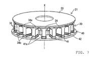
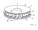
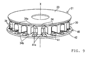
- FIG. 7 to FIG. 9 show different states when the moveable stator 40 is relatively rotated with respect to the fixed stator 30 around the center axis X. Note that, for the sake of explanatory simplicity, illustrations of the resin member 36 of the fixed stator 30 shown in FIG. 3 to FIG. 5 , the resin member 43 of the moveable stator 40, the crank shaft 51, and the coil 31 etc. are omitted. In addition, in FIG. 7 to FIG. 9 , the same members as shown in FIG. 3 to FIG. 5 are denoted with the same reference numerals.
- FIG. 7 shows a state when the second teeth 41 of the moveable stator 40 are aligned with the first teeth 34 of the fixed stator 30.
- the gap which generates magnetic resistance, between the end surface 34b at the second teeth 41 side of the first teeth 34 and the end surface 41a at the first teeth 34 side of the second teeth 41 is at its smallest value k (refer to FIG. 5 ).
- magnetic flux flow is generated in the first teeth 34 and the second teeth 41, the base 42, and each permanent magnet 24.
- This magnetic flux flow flows from the end surface 34a of the first teeth 34 at the permanent magnets 24 side to the end surface 34b on the opposite side. In other words, in this state, the magnetic flux flow flows within the coil 31.
- the rotating electric machine 20 functions as a rotating electric machine of a low torque high speed type.
- the magnetic flux flow is stronger than that shown in FIG. 9 , because it flows inside the coil 31, and the rotating electric machine 20 functions as a rotating electric machine of a high torque low speed type.
- the engine with attached rotating electric machine 50 of this embodiment with the above-described structure can use the rotating electric machine 20 to provide auxiliary drive for the crank shaft 51 that is caused to rotate around the center axis X by the piston.
- the engine with attached rotating electric machine 50 can stop the rotation of the crank shaft 51 caused by the piston, and use just the drive of the rotating electric machine 20 to run the motorcycle 1.
- stator 25 and the rotor 21 are disposed on an extension line of the center axis X of the crank shaft 51.
- size reduction as compared to the known technology can be promoted in which the rotating electric machine is connected to the crank shaft using a belt-type continuously variable transmission or the like.
- the cooling fan 65 can be fixed to the rotor 21 and caused to rotate along with the rotor 21.
- a structure is provided that makes it easier to cool the engine with attached rotating electric machine 50 while promoting size reduction, and easier to cool the radiator 66 that is disposed to the outside in the vehicle width direction of the engine with attached rotating electric machine 50.
- the engine with attached rotating electric machine 50 is extremely easy to mount.
- the engine with attached rotating electric machine 50 has a structure in which the drive mechanism 80 is attached to the crank case 60, and thus ease of mounting is improved still further.
- the cap shaped rotor 21 covers the gap between the rotor 21 and the stator 25, and thus it is difficult for foreign objects like dirt or the like to enter in to the gap. Accordingly, durability is substantially improved.
- the engine with attached rotating electric machine 50 has a structure in which the permanent magnets 24 are arranged inside the rotor 21, and thus it is possible to reliably reduce the size of the gap h in the center axis X direction between the facing permanent magnets 24 and the magnetic flux generating area 34a. Accordingly, the performance of the rotating electric machine 20 can be fully demonstrated.
- the gap adjustment mechanism formed by the above-described first regulation mechanism and the second regulation mechanism is provided between the crank case 60, the crank shaft 51, the rotor 21, and the stator 25.
- the fixed stator 30, which has a structure that is more complicated than the moveable stator 40, is fixed to the crank case 60, and thus the moveable stator 40 can be provided so as to be rotatable with respect to the crank case 60. Accordingly, the device structure of the engine with attached rotating electric machine 50 is simplified.
- the cooling fan 65 is fixed in an integrated manner at the outside in the vehicle width direction of the rotor 21.
- the engine with attached rotating electric machine 50 has a structure that makes it easier to cool the engine with attached rotating electric machine 50 using the cooling fan 65, and easier to cool the radiator 66 that is disposed to the outside in the vehicle width direction of the engine with attached rotating electric machine 50.
- rotational resistance is reduced.
- the cooling fan 65 intakes air from the vehicle width direction side, and blows out air to the outside in the radial direction with respect to the center axis X.
- the large intake port 66a can be provided in the outside in the vehicle width direction of the motorcycle 1 in which the engine with attached rotating electric machine 50 is mounted, thereby making it easier to intake cool external air and to lead exhausted air to the outside of the motorcycle 1.
- the radiator 66 is provided at the outside of the cooling fan 65 in the crank case 60. Moreover, the cool external air that is sucked in from the outside in the vehicle width direction by the cooling fan 65 directly hits the radiator 66, thereby improving the cooling effect and improving engine performance.
- the invention relates to an engine with an attached axial gap type rotating electric machine.
Landscapes
- Engineering & Computer Science (AREA)
- Mechanical Engineering (AREA)
- Power Engineering (AREA)
- Transportation (AREA)
- Combustion & Propulsion (AREA)
- Chemical & Material Sciences (AREA)
- Sustainable Development (AREA)
- Sustainable Energy (AREA)
- Life Sciences & Earth Sciences (AREA)
- Connection Of Motors, Electrical Generators, Mechanical Devices, And The Like (AREA)
- Permanent Magnet Type Synchronous Machine (AREA)
- Hybrid Electric Vehicles (AREA)
- Electric Propulsion And Braking For Vehicles (AREA)
Abstract
Description
- The present invention relates to an engine with an attached axial gap type rotating electric machine.
- A known engine with an attached axial gap type rotating electric machine is disclosed in
JP-A-2006-271040 - The axial gap type rotating electric machine is disposed in parallel to the crank shaft, and is provided with a rotating electric machine side shaft that has one end that is linked to the belt-type continuously variable transmission, a rotor that is fixed to the other end of the rotating electric machine side shaft, and a stator that is fixed to the crank case at a position further toward the other end than the rotor, with the rotating electric machine side shaft inserted therethrough.
- A plurality of permanent magnets are disposed orthogonal to the axial center of the rotating electric machine side shaft in a surface of the rotor that faces the stator. The stator has a magnetic flux generating area that faces each permanent magnet in the axial direction.
- More specifically, the stator includes a first stator that has first teeth that form the magnetic flux generating area, and a second stator that has second teeth that rotate relatively with respect to the first teeth around the axial center. The second teeth have a structure that allows a gap, which generates magnetic resistance, between the second teeth and the first teeth to be varied.
- The first stator is fixed to the crank case, and the second stator is provided with a driving mechanism that causes the second stator to rotate relatively with respect to the first stator.
- The known engine with the attached axial gap type rotating electric machine with the above-described structure is mounted in a straddle-type vehicle, most typically a motorcycle. Furthermore, the engine with the attached axial gap type rotating electric machine can be used to run a straddle-type vehicle. In this case, the axial gap type rotating electric machine provides auxiliary drive for the crank shaft that is driven to rotate around the axial center by the piston, or stops the rotation of the crank shaft caused by the piston such that the crank shaft is just driven by the axial gap type rotating electric machine.
- However, in this engine with the attached axial gap type rotating electric machine, a drive mechanism rotates the second stator, thereby changing the gap that generates the magnetic resistance between the first teeth and the second teeth. As a result, the relationship of the rotational speed and the rotational torque can be controlled. Accordingly, the engine with the attached axial gap type rotating electric machine can change the output characteristics of the axial gap type rotating electric machine in accordance with the running state of the straddle-type vehicle, for example, can change to a high torque low speed mode or a low torque high speed mode.
- However, in the known engine with the attached axial gap type rotating electric machine, the axial gap type rotating electric machine is connected to the crank shaft via a belt-type continuously variable transmission, which makes reducing the size of the engine with the attached axial gap type rotating electric machine difficult. As a result, the engine with the attached axial gap type rotating electric machine is more difficult to mount in the straddle-type vehicle etc.
- The invention seeks to provide an engine with an attached axial gap type rotating electric machine that is extremely easy to mount.
- An engine with an attached axial gap type rotating electric machine according to the invention includes: a crank case that includes therein a crank shaft, the crank shaft being driven to rotate around a center axis by a piston and being inserted within the crank case such the crank shaft can rotate; a rotor, fixed to one end side of the crank shaft at the outside of the crank case, that includes a plurality of permanent magnets that are orthogonal to the center axis; and a stator, fixed to the crank case with the crank shaft inserted therein, that has a magnetic flux generating area that faces the permanent magnets in the axial direction.
- In an embodiment of an engine according to the invention with the attached axial gap type rotating electric machine, the stator includes a first stator that has first teeth that form the magnetic flux generating area, and a second stator that has second teeth. A gap between the first teeth and the second teeth that generates magnetic resistance can be varied by rotating the second teeth around the center axis relative to the first teeth. The engine with the attached axial gap type rotating electric machine further includes a drive mechanism that relatively rotates either one or both of the first stator and the second stator.
- In an embodiment of an engine according to the invention with the attached axial gap type rotating electric machine (hereinafter, "axial gap type rotating electric machine" will be referred to simply as "rotating electric machine"), the stator and the rotor are disposed on an extension line of the center axis of the crank shaft. Thus, size reduction as compared to the known technology can be promoted in which the rotating electric machine is connected to the crank shaft using a belt-type continuously variable transmission or the like.
- In addition, in an embodiment of an engine according to the invention with attached rotating electric machine, because the rotor is disposed further to the outside than the stator, the fan that can blow air can be fixed to the rotor and caused to rotate along with the rotor. Thus, a structure is provided that makes it easier to cool the engine with attached rotating electric machine while promoting size reduction, and easier to cool a radiator that is disposed in the vicinity of the engine with attached rotating electric machine.
- Accordingly, an embodiment of an engine according to the invention with attached rotating electric machine can be mounted extremely easily.
- The manner in which the stator is fixed to the crank case includes, in addition to directly fixing the stator to the crank case, indirectly fixing the stator to the crank case via a cover or the like that is included as a component of the crank case.
- In an embodiment of an engine according to the invention with the attached rotating electric machine, the drive mechanism may be attached to a vehicle body frame or the like, or alternatively may be attached to the crank case. If the latter structure is adopted, ease of mounting is improved still further.
- The manner in which the drive mechanism is attached to the crank case includes, in addition to directly fixing the drive mechanism to the crank case, indirectly fixing the drive mechanism to the crank case via the cover or the like that is included as a component of the crank case.
- In an embodiment of an engine according to the invention with attached rotating electric machine, the rotor has a cup like shape and includes a yoke that extends from the center axis in the radial direction, and an outer cylindrical member, extending from an outer periphery edge of the yoke toward the stator side, that covers, at the least, a section of an outer periphery of the stator. With this structure, the cup shaped rotor covers the gap between the rotor and the stator, and thus it is difficult for foreign objects like dirt or the like to enter in to the gap. Accordingly, durability is substantially improved.
- In an embodiment of an engine according to the invention with attached rotating electric machine, the permanent magnets may be embedded in the rotor and arranged together. However, it is favorable that the permanent magnets are arranged inside the rotor. If a structure is adopted in which the permanent magnets are arranged inside the rotor, it is possible to reliably reduce the size of the gap in the axial direction between the facing permanent magnets and the magnetic flux generating area. Accordingly, the engine with attached rotating electric machine can fully demonstrate the performance of the rotating electric machine.
- An embodiment of an engine according to the invention with attached rotating electric machine may further include a gap adjustment mechanism, provided between the crank case, the crank shaft, the rotor and the stator, that determines a gap between the permanent magnets and the magnetic flux generating area in the axial direction. If this structure is adopted, the engine with attached rotating electric machine is able to reliably reduce the occurrence of variation in the gap in the axial direction between the permanent magnets and the magnetic flux generating area, thereby allowing the performance of the rotating electric machine to be reliably demonstrated to an even higher level.
- In an embodiment of an engine according to the invention with attached rotating electric machine, the gap adjustment mechanism may include a first regulation mechanism that regulates a position in the axial direction of the crank shaft and the rotor, and a second regulation mechanism that regulates a position in the axial direction of the crank case and the stator while providing tolerance for variation in the position in the axial direction of the crank shaft and the rotor. If this structure is adopted, the engine with attached rotating electric machine is able to reliably reduce the occurrence of variation in the gap in the axial direction between the permanent magnets and the magnetic flux generating area, thereby allowing the performance of the rotating electric machine to be reliably demonstrated to an even higher level.
- In an embodiment of an engine according to the invention with attached rotating electric machine, the first regulation mechanism has a structure in which one end of the crank shaft and the rotor are fitted together using a tapered structure, and the second regulation mechanism has a structure that includes a bearing support member that is provided in an outer periphery surface of a small diameter cylindrical member that protrudes from a center of the rotor toward the stator side, a bearing support member that is provided in an inner periphery surface of the stator, a bearing that is provided between the bearing support members, and an engagement pin and an engagement hole, respectively provided in the stator and the crank case, that provide tolerance for mutual movement in the axial direction.
- If this structure is adopted, it is possible to reliably reduce the occurrence of variation in the gap in the axial direction between the permanent magnets and the magnetic flux generating area. Note that, in a modified example of the first regulation mechanism, the crank shaft and the rotor can be spline-engaged.
- In an embodiment of an engine according to the invention with attached rotating electric machine, it is favorable if the first stator is fixed to the crank case, and the second stator is rotatably provided on the crank case. If this structure is adopted, in the engine with attached rotating electric machine, there is no need to rotate the first teeth, which have a structure that is more complicated than the second teeth and that form the magnetic flux generating area, and thus the device structure of the engine can be simplified.
- An embodiment of an engine according to the invention with attached rotating electric machine may further include: a fan that can blow wind that is fixed to and integrated with the outside of the rotor. Thus, the engine with attached rotating electric machine has a structure that makes it easier to cool the engine with attached rotating electric machine using the fan, and easier to cool the radiator that is disposed in the vicinity of the engine with attached rotating electric machine. In addition, as a result of integrally fixing the fan to the rotor that is lighter than the stator, rotational resistance is reduced.
- In an embodiment of an engine according to the invention with attached rotating electric machine of the invention, the fan may intake air from the outside in the axial direction, and blow out air to the outside in the radial direction with respect to the center axis. If this structure is adopted, a large intake port can be provided in the outside in the vehicle width direction of the straddle-type vehicle or the like in which the engine with attached rotating electric machine is mounted, thereby making it easier to intake cool external air that has not been heated by the engine with attached rotating electric machine, and to lead exhausted air to the outside of the vehicle, such as a straddle-type vehicle.
- The fan that intakes air from the outside in the axial direction and that blows the air to the outside in the radial direction with respect to the center axis may be a sirocco fan. However, the fan is not limited to this, and may be a turbo fan, or a combination of a sirocco fan and a turbo fan.
- An embodiment of an engine according to the invention with attached rotating electric machine may further include: a radiator that is provided in the crank case to the outside of the fan. If this structure is adopted, the engine with attached rotating electric machine can improve engine performance using water cooling. More particularly, if the fan is of a type that intakes air from the outside in the axial direction, cool external air can be caused to hit the radiator, thereby effectively cooling the radiator.
- Embodiments of the invention are described hereinafter, by way of example only, with reference to the accompanying drawings.
-
FIG. 1 is side view of a motorcycle in which an engine with an attached rotating electric machine of an embodiment is mounted. -
FIG. 2 shows the engine with the attached rotating electric machine of the embodiment in a side view of a rear section of the motorcycle ofFIG. 1 -
FIG. 3 shows the engine with the attached rotating electric machine of the embodiment along a cross section III-III ofFIG. 2 . -
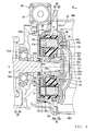
FIG. 4 shows the engine with the attached rotating electric machine of the embodiment, and is an expanded cross sectional view of the rotating electric machine of the cross sectional view ofFIG. 3 . -
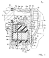
FIG. 5 shows the engine with the attached rotating electric machine of the embodiment, and is an expanded cross sectional view of a stator of the cross sectional view ofFIG. 4 . -
FIG. 6 is a schematic outline view of a drive mechanism of the engine with the attached rotating electric machine of the embodiment. -
FIG. 7 shows the engine with the attached rotating electric machine of the embodiment and shows a state when a moveable stator has rotated relative to a fixed stator. -
FIG. 8 shows the engine with the attached rotating electric machine of the embodiment, and shows a state when the moveable stator has rotated relative to the fixed stator. -
FIG. 9 shows the engine with the attached rotating electric machine of the embodiment, and shows a state when the moveable stator has rotated relative to the fixed stator. - Hereinafter, embodiments of the invention will be described with reference to the drawings.
- As can be seen from
FIG. 1 to FIG. 4 , an engine with an attached axial gap type rotating electric machine 50 (hereinafter simply referred to as "engine with attached rotatingelectric machine 50") of this embodiment is mounted in amotorcycle 1. - The
motorcycle 1, as shown inFIG. 1 , is provided with a front wheel 3 at a vehicle body front lower section. The front wheel 3 is rotatably supported by a lower end section of a front fork 5. A steering shaft 7 that extends upwards is connected to an upper end section of the front fork 5. A handle 9 that extends in the vehicle width direction is attached to an upper end section of the steering shaft 7. Grips 11 are attached to either end of the handle 9. Avehicle body frame 10 is attached to a central section of the steering shaft 7. - The
vehicle body frame 10 extends diagonally downward toward a vehicle body rear section, and then curves to extend horizontally. Then, thevehicle body frame 10 curves again before extending straight. Aseat 13 is disposed on a rear upper side of thevehicle body frame 10. An upper end section of arear suspension 15 is connected to a rear end section of thevehicle body frame 10. - As can be seen from
FIG. 2 , a lower end section of therear suspension 15 is connected to arear end section 16a of arear arm 16 that is one section of thevehicle body frame 10. Therear arm 16 rotatably supports arear wheel 17. Driving force of the engine with attached rotatingelectric machine 50 is transmitted to therear wheel 17 via a drive force transmission mechanism such as a belt-type continuously variable transmission, thus rotatably driving therear wheel 17. The engine with attached rotatingelectric machine 50 is disposed beneath the central section of thevehicle body frame 10. - As shown in
FIG. 3 , the engine with attached rotatingelectric machine 50 is provided with a crankcase 60, acrank shaft 51, and an axial gap type rotating electric machine 20 (hereinafter simply referred to as "rotatingelectric machine 20"). - The crank
case 60 includes a crankcase body 61, and a crank case cover 62 that is positioned to the outside in the vehicle width direction (the direction indicated by α shown inFIG. 3 ) of thecrank case body 61. The crank case cover 62 has a generally flat tabular shape. Anengagement member 62b is formed in the crank case cover 62 in the inside in the vehicle width direction (the direction opposite to that indicated by α inFIG. 3 ). Theengagement member 62b is fitted in to an engagedmember 61b that is formed in the outside in the vehicle width direction of thecrank case body 61. As a result, the crank case cover 62 is assembled as an integrated unit with thecrank case body 61. - An
insertion hole 61a that has a center axis that is aligned with a center axis X of thecrank shaft 51 is formed in the outside in the vehicle width direction of thecrank case body 61. Aninsertion hole 62a that has a center axis that is aligned with the center axis X is also formed in thecrank case cover 62. - The
crank shaft 51 is disposed inside thecrank case body 61, and is connected via a connectingrod 50c to a piston (not shown in the figures) that is housed within a cylinder (not shown in the figures) that is provided in a central section of the engine with attached rotatingelectric machine 50. Anend section 51c to the outside in the vehicle width direction of thecrank shaft 51 extends through theinsertion holes insertion hole 62a. - A
bearing 52a that rotatably supports thecrank shaft 51 such that it rotates around the center axis X is disposed between thecrank shaft 51 and theinsertion hole 61a. In addition, abearing 52b that rotatably supports thecrank shaft 51 such that it rotates around the center axis X is provided in thecrank case body 61. As a result, thecrank shaft 51 is driven to rotate around the center axis X inside thecrank case 60 by the up-down motion of the piston. Moreover, aseal member 54 that seals a gap between thecrank shaft 51 and the crankcase 60 is provided between thecrank shaft 51 and theinsertion hole 62a. - The rotating
electric machine 20 is disposed at the outside in the vehicle width direction of thecrank case 60. The rotatingelectric machine 20 is provided with arotor 21, astator 25, and adrive mechanism 80. - The
rotor 21, as can be seen fromFIG. 4 , includes a small diametercylindrical member 22, ayoke 23, and an outercylindrical member 23a. An inner periphery surface of the small diametercylindrical member 22 is formed as atapered surface 22a that has a diameter that becomes smaller as thetapered surface 22a extends toward the outside in the vehicle width direction. On the other hand, an outer periphery surface of theend section 51c of thecrank shaft 51 is formed as atapered surface 51b that has a diameter that becomes smaller as thetapered surface 51b extends toward the outside in the vehicle width direction. Accordingly, when the small diametercylindrical member 22 of therotor 21 is fitted to theend section 51c of thecrank shaft 51, thetapered surface 51b is placed in contact with thetapered surface 22a. In addition, anut 57 is screwed on to a male screw formed in theend section 51c. Thenut 57 presses therotor 21 toward the central section of thecrank shaft 51, whereby the taperedsurface 51b and thetapered surface 22a are held together under pressure. As a result of adopting this structure, therotor 21 is fixed to theend section 51c side of thecrank shaft 51, and the position of therotor 21 in the center axis X direction with respect to thecrank shaft 51 is determined. - The structure in which the
end section 51c of thecrank shaft 51 and therotor 21 are fitted together using tapered surfaces, namely, using the taperedsurface 51b and thetapered surface 22a, corresponds to a first regulation mechanism that regulates the position of thecrank shaft 51 and therotor 21 in the center axis X direction. In addition, with the first regulation mechanism, there is a possibility that variation in the position of thecrank shaft 51 and therotor 21 in the center axis X direction may occur as a result of the characteristics of the taper fit. However, a second regulation mechanism described later is structured so as to provide tolerance for such variation. - A
groove 22h that extends in the center axis X direction is formed in the taperedsurface 22a of the small diametercylindrical member 22. On the other hand, a recess having a semicircular shape is formed in the taperedsurface 51b of theend section 51c of thecrank shaft 51. A key 22g with a corresponding shape is fitted in to this recess. An edge of the key 22g protrudes from the taperedsurface 51b, and engages with thegroove 22h. As a result of adopting this structure, the key 22g is engaged with both therotor 21 and thecrank shaft 51, thereby providing a structure in which therotor 21 rotates along with thecrank shaft 51. - The
yoke 23 has a generally disk like shape that extends from the small diametercylindrical member 22 in the radial direction. In addition, a plurality of permanent magnets 24 (field magnets) are fixed to the inside in the vehicle width direction of theyoke 23, and are arranged in a circular manner and orthogonal to the center axis X. - The outer
cylindrical member 23a is a cylindrical body that covers at least a section of the outer periphery of thestator 25, described hereinafter, and extends toward the inside in the vehicle width direction from an outer periphery edge of theyoke 23. Due to providing theyoke 23 and the outercylindrical member 23a, the rotor has a cup like shape, and thus a gap between therotor 21 and thestator 25 is covered. Accordingly, it is difficult for foreign objects like dirt or the like to enter in to the gap between therotor 21 and thestator 25. - A cooling
fan 65 that functions as a fan that can generate air flow is integrally fixed by abolt 65a to the outside in the vehicle width direction of theyoke 23. The coolingfan 65 is a sirocco fan that is thin in the center axis X direction. The coolingfan 65 is formed by a plurality of integrated vanes that can intake air from the outside in the center axis X direction (outside in the vehicle width direction), and can blow out the air to the outside in the radial direction with respect to the center axis X. - As can be seen from
FIG. 3 , aradiator 66 is disposed at the outside in the vehicle width direction of the coolingfan 65. Theradiator 66 is assembled together with a support member (not shown in the figures) that extends toward the outside in the vehicle width direction from thecrank case 60. Alarge intake port 66a is disposed at the outside in the vehicle width direction of theradiator 66. Cool external air, which enters via theintake port 66a from the outside in the vehicle width direction as a result of rotation of the coolingfan 65, directly hits theradiator 66. As a result, coolant that circulates between theradiator 66 and a cylinder block (not shown in the figures) of theengine 50 is effectively cooled. In addition, adischarge port 66b is provided at the outside in the radial direction of the coolingfan 65. Air that is discharged from the coolingfan 65 to the outside in the radial direction can be smoothly discharged to the outside of the vehicle. Note that, hypothetically speaking, if the blow direction of the coolingfan 65 is reversed, air that is warmed by the heat of the engine with attached rotatingelectric machine 50 hits theradiator 66, whereby cooling efficiency is lowered. However, the above-described structure eliminates the possibility of this type of problem occurring. - The
stator 25 is fixed to the outside in the vehicle width direction of thecrank case 60 with thecrank shaft 51 inserted therein. Thestator 25 is disposed further to the inside in the vehicle width direction than therotor 21. In addition, thestator 25 has an end surface (magnetic flux generating area) 34a that faces each of thepermanent magnets 24 in the center axis X direction. - More specifically, the
stator 25 is provided with a fixedstator 30 that functions as a first stator that is positioned on therotor 21 side, and amoveable stator 40 that functions as a second stator that is positioned at the crank case cover 62 side. - As can be seen from
FIG. 3 to FIG. 5 , the fixedstator 30 is provided with a plurality offirst teeth 34 formed by magnetic cores. Eachfirst tooth 34 is arranged in a ring like shape that encircles thecrank shaft 51. The end surface (magnetic flux generating area) 34a of eachfirst tooth 34 at therotor 21 side faces eachpermanent magnet 24 of therotor 21. - A
coil 31 that generates a magnetic flux when energized is wound around eachfirst tooth 34. Thefirst teeth 34 and thecoil 31 are molded in to aresin member 36 that is made from resin and that includes a lubricant. Theresin member 36 is formed in a ring like shape that centers on the center axis X. As shown in the enlarge view ofFIG. 5 , theresin member 36 has aninner periphery section 36b that is generally cylindrical and positioned at the inside in the diameter direction of a coil group that is made up of a plurality ofcoils 31. In addition, theresin member 36 has anouter periphery section 36a that is generally cylindrical and positioned at the outside in the diameter direction of the coil group that is made up of the plurality ofcoils 31. - The
outer periphery section 36a has aprotrusion 36c that extends toward the crank case cover 62 side (the inside in the vehicle width direction). A plurality of engagement holes 37 are formed in an end surface of theprotrusion 36c at the crank case cover 62 side (the inside in the vehicle width direction) and extend parallel with the center axis X. On the other hand, a plurality of engagement pins 59 that protrude toward the outside in the vehicle width direction are formed at positions that correspond with the respective engagement holes 37 of the crank case cover 62 such that the engagement pins 59 can fit in to the respective engagement holes 37. In addition, eachengagement pin 59 is fitted in to eachengagement hole 37 so that the fixedstator 30 is fixed to the crank case cover 62 so as not to be capable of rotation around the center axis X. The depth of eachengagement hole 37 is made larger than the protrusion length of eachengagement pin 59. Therefore, the relative position of eachengagement hole 37 and eachengagement pin 59 is not restricted in the center axis X direction. - A
radial bearing 63 is disposed between an inner periphery surface of theinner periphery section 36b and an outer periphery surface of the small diametercylindrical member 22. - More particularly, a
bearing support member 36i is provided in the inner periphery surface of theinner periphery section 36b. Thisbearing support member 36i includes a bearingcontact surface 36j and a bearingsupport surface 36c. The bearingsupport surface 36c is formed to be perpendicular to the center axis X, namely, faces therotor 21. The bearingsupport surface 36c is positioned in the vicinity of a center point between an end section of theinner periphery section 36b at therotor 21 side and an end section of theinner periphery section 36b at themoveable stator 40 side. The bearingcontact surface 36j is formed to have a cylindrical shape that centers on the center axis X, and contacts anouter periphery surface 63a of theradial bearing 63. - In addition, a
bearing support member 22e is formed at an outer periphery side of the small diametercylindrical member 22. Thebearing support member 22e includes a bearingcontact surface 22f and a bearingsupport surface 22d. The bearingsupport surface 22d is formed to be perpendicular to the center axis X, namely, faces the fixedstator 30. The bearingsupport surface 22d is positioned in the vicinity of a center point in the center axis X direction of the small diametercylindrical member 22. The bearingcontact surface 22f is formed to have a cylindrical shape that centers on the center axis X, and contacts aninner periphery surface 63b of theradial bearing 63. - The
radial bearing 63 is disposed between the bearingsupport surface 36c and the bearingsupport surface 22d in the center axis X direction. Note that, in the above explanation, because the respective engagement holes 37 and the engagement pins 59 do not have their respective relative positions in the center axis X direction regulated, the fixedstator 30 is pulled toward therotor 21 side by magnetism of thepermanent magnets 24. At this time, the bearingsupport surface 22d supports the fixedstator 30 via theradial bearing 63 and the bearingsupport surface 36c in resistance to the attracting force (the magnetism). As a result, a gap h is maintained between the facingsurface 24a of eachpermanent magnet 24 that faces the fixedstator 30 and the end surfaces (the magnetic flux generating area) 34a of thefirst teeth 34 that face thepermanent magnets 24. Note that, the gap h is more specifically the gap between eachpermanent magnet 24 and the end surfaces (the magnetic flux generating area) 34a in the center axis X direction. The gap h can be determined by the position of the bearingsupport surface 36c of the fixedstator 30, the width of theradial bearing 63 in the center axis X direction, and the position of the bearingsupport surface 22d of the small diametercylindrical member 22. - In addition, the
radial bearing 63 is in contact with both the bearingcontact surface 36j of the fixedstator 30 and the bearingcontact surface 22f of the small diametercylindrical member 22. Thus, theradial bearing 63 can provide support such that relative rotation is possible, without causing diameter direction misalignment of the fixedstator 30 or therotor 21. - The
radial bearing 63, the bearingsupport member 36i of the fixedstator 30, the bearingsupport member 22e of the small diametercylindrical member 22, the engagement holes 37, and the engagement pins 59 correspond to a second regulation mechanism that permits variation in the position in the center axis X direction of thecrank shaft 51 and therotor 21, but regulates the position in the center axis X direction of thecrank case 60 and thestator 25. In addition, the second regulation mechanism and the above-described first regulation mechanism form a gap adjustment mechanism that determines the gap h in the center axis X direction between thepermanent magnets 24 and the end surfaces (magnetic flux generating area) 34a. - Next, the
moveable stator 40 will be explained. Themoveable stator 40, as described above, is disposed further to the crank case cover 62 side than the fixedstator 30 with respect to therotor 21, and faces the fixedstator 30. - The
moveable stator 40 is provided withsecond teeth 41, and a ring shapedbase 42. The number of providedsecond teeth 41 is the same as thefirst teeth 34. Thebase 42 supports thesecond teeth 41 that are arranged in a ring like shape centering on the center axis X. Thebase 42 and thesecond teeth 41 are molded in to aresin member 43 that is made from resin and that includes a lubricant. Eachsecond tooth 41 is formed by a magnetic core. Magnetism generation by energization of thecoil 31 exerts a force that pulls thesecond teeth 41 toward thefirst teeth 34 side. However, a holding member (not shown in the figures) holds thesecond teeth 41 such that there is a determined distance of separation from thefirst teeth 34 in the center axis X direction. In addition, themoveable stator 40, as described below, is capable of relative rotation with respect to the fixedstator 30 around the center axis X direction. - The
drive mechanism 80, as can be seen fromFIG. 4 andFIG. 6 , is disposed at the outside in the vehicle width direction of thecrank case cover 62, and to the outside in the diameter direction of themoveable stator 40. Thedrive mechanism 80 includes adrive motor 81 and thegear mechanism 82. Thegear mechanism 82 includes aworm gear 82a, aworm wheel 82b, and a missingtooth gear 82c. When thedrive motor 81 rotates, as shown inFIG. 6 , theworm wheel 82b rotates within a determined angular range, and driving force is transmitted to a missingtooth gear 82d that is formed on a section of the outer periphery surface of themoveable stator 40 via the missingtooth gear 82c. As a result, in thedrive mechanism 80, when thedrive motor 81 rotates in the forward or reverse direction, themoveable stator 40 turns around the center axis X, and rotates relative to the fixedstator 30. - In the rotating
electric machine 20 with the above-described structure, relative rotation of themoveable stator 40 and the fixedstator 30 causes change in output characteristics as described below. Thus drive can be performed at high torque low speed or at low torque high speed. -
FIG. 7 to FIG. 9 show different states when themoveable stator 40 is relatively rotated with respect to the fixedstator 30 around the center axis X. Note that, for the sake of explanatory simplicity, illustrations of theresin member 36 of the fixedstator 30 shown inFIG. 3 to FIG. 5 , theresin member 43 of themoveable stator 40, thecrank shaft 51, and thecoil 31 etc. are omitted. In addition, inFIG. 7 to FIG. 9 , the same members as shown inFIG. 3 to FIG. 5 are denoted with the same reference numerals. -
FIG. 7 shows a state when thesecond teeth 41 of themoveable stator 40 are aligned with thefirst teeth 34 of the fixedstator 30. In this state, the gap, which generates magnetic resistance, between theend surface 34b at thesecond teeth 41 side of thefirst teeth 34 and theend surface 41a at thefirst teeth 34 side of thesecond teeth 41 is at its smallest value k (refer toFIG. 5 ). At this time, magnetic flux flow is generated in thefirst teeth 34 and thesecond teeth 41, thebase 42, and eachpermanent magnet 24. This magnetic flux flow flows from theend surface 34a of thefirst teeth 34 at thepermanent magnets 24 side to theend surface 34b on the opposite side. In other words, in this state, the magnetic flux flow flows within thecoil 31. - When drive of the
drive mechanism 80 causes themoveable stator 40 to rotate through the intermediate position shown inFIG. 8 to the position shown inFIG. 9 , namely, where thesecond teeth 41 has rotated to a center position between thefirst teeth 34 and neighboringfirst teeth 34, the gap, which generates magnetic resistance, between theend surface 34b at thesecond teeth 41 side of thefirst teeth 34 and theend surface 41a at thefirst teeth 34 side of thesecond teeth 41 becomes larger. At this time, the magnetic flux flow does not flow in thesecond teeth 41, and a magnetic flux flow flows in thepermanent magnets 24 and thefirst teeth 34 in the vicinity of therotor 21. This magnetic flux flow does not flow inside thecoil 31, and thus as compared to the state shown inFIG. 7 , the magnetic flux flow is weak. In the state shown inFIG. 9 , because the magnetic flux flow is weak, the rotatingelectric machine 20 functions as a rotating electric machine of a low torque high speed type. On the other hand, in the state shown inFIG. 7 , the magnetic flux flow is stronger than that shown inFIG. 9 , because it flows inside thecoil 31, and the rotatingelectric machine 20 functions as a rotating electric machine of a high torque low speed type. - The engine with attached rotating
electric machine 50 of this embodiment with the above-described structure can use the rotatingelectric machine 20 to provide auxiliary drive for thecrank shaft 51 that is caused to rotate around the center axis X by the piston. In addition, the engine with attached rotatingelectric machine 50 can stop the rotation of thecrank shaft 51 caused by the piston, and use just the drive of the rotatingelectric machine 20 to run themotorcycle 1. - Note that, in the engine with attached rotating
electric machine 50 of this embodiment, thestator 25 and therotor 21 are disposed on an extension line of the center axis X of thecrank shaft 51. Thus, size reduction as compared to the known technology can be promoted in which the rotating electric machine is connected to the crank shaft using a belt-type continuously variable transmission or the like. - In addition, in the engine with attached rotating
electric machine 50, because therotor 21 is disposed further to the outside in the vehicle width direction than thestator 25, the coolingfan 65 can be fixed to therotor 21 and caused to rotate along with therotor 21. Thus, a structure is provided that makes it easier to cool the engine with attached rotatingelectric machine 50 while promoting size reduction, and easier to cool theradiator 66 that is disposed to the outside in the vehicle width direction of the engine with attached rotatingelectric machine 50. - Accordingly, the engine with attached rotating
electric machine 50 is extremely easy to mount. - Moreover, the engine with attached rotating
electric machine 50 has a structure in which thedrive mechanism 80 is attached to the crankcase 60, and thus ease of mounting is improved still further. - In addition, in the engine with attached rotating
electric machine 50, the cap shapedrotor 21 covers the gap between therotor 21 and thestator 25, and thus it is difficult for foreign objects like dirt or the like to enter in to the gap. Accordingly, durability is substantially improved. - Furthermore, the engine with attached rotating
electric machine 50 has a structure in which thepermanent magnets 24 are arranged inside therotor 21, and thus it is possible to reliably reduce the size of the gap h in the center axis X direction between the facingpermanent magnets 24 and the magneticflux generating area 34a. Accordingly, the performance of the rotatingelectric machine 20 can be fully demonstrated. - In addition, in the engine with attached rotating
electric machine 50, the gap adjustment mechanism formed by the above-described first regulation mechanism and the second regulation mechanism is provided between thecrank case 60, thecrank shaft 51, therotor 21, and thestator 25. Thus, it is possible to reliably reduce the occurrence of variation in the gap h in the center axis X direction between thepermanent magnets 24 and the magneticflux generating area 34a, thereby allowing the performance of the rotatingelectric machine 20 to be reliably demonstrated to an even higher level. - In addition, in the engine with attached rotating
electric machine 50, the fixedstator 30, which has a structure that is more complicated than themoveable stator 40, is fixed to the crankcase 60, and thus themoveable stator 40 can be provided so as to be rotatable with respect to the crankcase 60. Accordingly, the device structure of the engine with attached rotatingelectric machine 50 is simplified. - Furthermore, in the engine with attached rotating
electric machine 50, the coolingfan 65 is fixed in an integrated manner at the outside in the vehicle width direction of therotor 21. Thus, the engine with attached rotatingelectric machine 50 has a structure that makes it easier to cool the engine with attached rotatingelectric machine 50 using the coolingfan 65, and easier to cool theradiator 66 that is disposed to the outside in the vehicle width direction of the engine with attached rotatingelectric machine 50. In addition, as a result of integrally fixing the coolingfan 65 to therotor 21 that is lighter than thestator 25, rotational resistance is reduced. - Moreover, in the engine with attached rotating
electric machine 50, the coolingfan 65 intakes air from the vehicle width direction side, and blows out air to the outside in the radial direction with respect to the center axis X. Thus, thelarge intake port 66a can be provided in the outside in the vehicle width direction of themotorcycle 1 in which the engine with attached rotatingelectric machine 50 is mounted, thereby making it easier to intake cool external air and to lead exhausted air to the outside of themotorcycle 1. - In addition, in the engine with attached rotating
electric machine 50, theradiator 66 is provided at the outside of the coolingfan 65 in thecrank case 60. Moreover, the cool external air that is sucked in from the outside in the vehicle width direction by the coolingfan 65 directly hits theradiator 66, thereby improving the cooling effect and improving engine performance. - Hereinabove, an embodiment of the invention is described. However, the invention is not limited to this embodiment, and can be modified and applied as appropriate within the range implied by the scope of the claimed invention.
- The invention relates to an engine with an attached axial gap type rotating electric machine.
-
- 20 ... Axial gap type rotating electric machine
- 21 ... Rotor
- 23 ... Yoke
- 23a ... Outer cylindrical member
- 24 ... Permanent magnets
- 25 ... Stator
- 30 ... First stator (fixed stator)
- 40 ... Second stator (moveable stator)
- 34 ... First teeth
- 34a ... Magnetic flux generating area (end surface at rotor side of each first teeth)
- 41 ... Second teeth
- 50 ... Engine with the attached axial gap type rotating electric machine
- 51 ... Crank shaft
- 51c ... One end of crank shaft (end section)
- 60 ... Crank case (61 ... Crank case body, 62 ... Crank case cover)
- 61a, 62a ... Insertion hole
- 65 ... Fan (Cooling fan)
- 66 ... Radiator
- 80 ... Drive mechanism
- 51, 51b, 22, 22a, 63, 36i, 22e, 37, 59 ... Gap adjustment mechanism (51, 51b, 22, 22a ... First regulation mechanism, 63, 36i, 22e, 37, 59 ... Second regulation mechanism)
- 22a ... Tapered surface
- 51b ... Tapered surface
- 22e, 36i ... Bearing support member
- 63 ... Bearing
- 59 ... Engagement pins
- 37 ... Engagement holes
- X ... Center axis
- h ... Gap in axial direction between permanent magnets and magnetic flux generating area
Claims (11)
- An engine with an attached axial gap type rotating electric machine, comprising:a crank case that includes therein a crank shaft, the crank shaft being driven to rotate around a center axis by a piston and being inserted within the crank case such the crank shaft can rotate;a rotor, fixed to one end side of the crank shaft at the outside of the crank case, that includes a plurality of permanent magnets that are orthogonal to the center axis; anda stator, fixed to the crank case with the crank shaft inserted therein, that has a magnetic flux generating area that faces the permanent magnets in the axial direction, whereinthe stator includes a first stator that has first teeth that form the magnetic flux generating area, and a second stator that has second teeth, wherein a gap between the first teeth and the second teeth that generates magnetic resistance can be varied by rotating the second teeth around the center axis relative to the first teeth, the engine with the attached axial gap type rotating electric machine further comprising:a drive mechanism that relatively rotates either one or both of the first stator and the second stator.
- The engine according to claim 1, wherein the drive mechanism is attached to the crank case.
- The engine according to claim 1 or claim 2, wherein the rotor has a cup like shape and includes a yoke that extends from the center axis in the radial direction, and an outer cylindrical member, extending from an outer periphery edge of the yoke toward the stator side, that covers, at the least, a section of an outer periphery of the stator.
- The engine according to claim 3, wherein each of the permanent magnets is disposed inside the rotor.
- The engine according to any preceding claim, further comprising: a gap adjustment mechanism, provided between the crank case, the crank shaft, the rotor and the stator, that determines a gap between the permanent magnets and the magnetic flux generating area in the axial direction.
- The engine according to claim 5, wherein the gap adjustment mechanism includes a first regulation mechanism that regulates a position in the axial direction of the crank shaft and the rotor, and a second regulation mechanism that regulates a position in the axial direction of the crank case and the stator while providing tolerance for variation in the position in the axial direction of the crank shaft and the rotor.
- The engine according to claim 6 wherein
the first regulation mechanism has a structure in which one end of the crank shaft and the rotor are fitted together using a tapered structure, and
the second regulation mechanism has a structure that includes a bearing support member that is provided in an outer periphery surface of a small diameter cylindrical member that protrudes from a center of the rotor toward the stator side, a bearing support member that is provided in an inner periphery surface of the stator, a bearing that is provided between the bearing support members, and an engagement pin and an engagement hole, respectively provided in the stator and the crank case, that provide tolerance for mutual movement in the axial direction. - The engine according to any preceding claim, wherein the first stator is fixed to the crank case, and the second stator is rotatably provided on the crank case.
- The engine according to any preceding claim, further comprising:a fan that can blow wind that is fixed to and integrated with the outside of the rotor.
- The engine according to claim 9, wherein the fan intakes air from the outside in the axial direction, and blows out air to the outside in the radial direction with respect to the center axis.
- The engine according to claim 9 or claim 10, further comprising:a radiator that is provided in the crank case to the outside of the fan.
Applications Claiming Priority (1)
| Application Number | Priority Date | Filing Date | Title |
|---|---|---|---|
| JP2007026941A JP2008193841A (en) | 2007-02-06 | 2007-02-06 | Axial gap type engine with rotating electric machine |
Publications (2)
| Publication Number | Publication Date |
|---|---|
| EP1955939A2 true EP1955939A2 (en) | 2008-08-13 |
| EP1955939A3 EP1955939A3 (en) | 2015-02-18 |
Family
ID=39434195
Family Applications (1)
| Application Number | Title | Priority Date | Filing Date |
|---|---|---|---|
| EP08250300.4A Withdrawn EP1955939A3 (en) | 2007-02-06 | 2008-01-24 | Engine with attached axial gap type rotating electric machine |
Country Status (6)
| Country | Link |
|---|---|
| US (1) | US7800277B2 (en) |
| EP (1) | EP1955939A3 (en) |
| JP (1) | JP2008193841A (en) |
| CN (1) | CN101242123B (en) |
| BR (1) | BRPI0800151A (en) |
| TW (1) | TWI347276B (en) |
Cited By (3)
| Publication number | Priority date | Publication date | Assignee | Title |
|---|---|---|---|---|
| EP2159093A1 (en) * | 2008-08-29 | 2010-03-03 | Yamaha Hatsudoki Kabushiki Kaisha | Motorcycle |
| EP2055520A3 (en) * | 2007-10-30 | 2012-10-10 | Yamaha Hatsudoki Kabushiki Kaisha | Radiator cover and straddle-type vehicle having the same |
| EP2955822A1 (en) * | 2014-06-11 | 2015-12-16 | Samsung Electronics Co., Ltd | Brushless motor |
Families Citing this family (26)
| Publication number | Priority date | Publication date | Assignee | Title |
|---|---|---|---|---|
| ITMI20070528A1 (en) * | 2007-03-16 | 2008-09-17 | Piaggio & C Spa | HYBRID PROPULSION AND TRANSMISSION SYSTEM FOR MOTOR VEHICLES |
| JP5058035B2 (en) * | 2008-03-11 | 2012-10-24 | 富士重工業株式会社 | General purpose engine |
| JP5058034B2 (en) * | 2008-03-11 | 2012-10-24 | 富士重工業株式会社 | General purpose engine |
| KR100989684B1 (en) * | 2009-01-19 | 2010-10-26 | 뉴모텍(주) | Axial type motor |
| JP5356087B2 (en) * | 2009-03-27 | 2013-12-04 | 本田技研工業株式会社 | Electric vehicle |
| JP5503243B2 (en) * | 2009-09-30 | 2014-05-28 | 本田技研工業株式会社 | Hybrid motorcycle |
| US8212438B2 (en) * | 2010-01-19 | 2012-07-03 | U.S. Alternate Energy, LLC | Coolant system for electric motorcycle |
| JP5460566B2 (en) * | 2010-12-13 | 2014-04-02 | 株式会社日立製作所 | Axial gap type rotating electrical machine |
| JP5544379B2 (en) * | 2012-01-19 | 2014-07-09 | 富士重工業株式会社 | Axial gap type power generator |
| JP5538448B2 (en) * | 2012-01-19 | 2014-07-02 | 富士重工業株式会社 | Axial gap type power generator |
| US9197109B2 (en) * | 2012-03-08 | 2015-11-24 | Stainless Motors, Inc. | Electric motor configured for facilitated washability |
| JP5645028B2 (en) * | 2012-11-06 | 2014-12-24 | 株式会社安川電機 | Rotating electric machine |
| JP6034160B2 (en) * | 2012-11-29 | 2016-11-30 | 富士重工業株式会社 | Power generation unit |
| JP5773499B2 (en) * | 2012-12-11 | 2015-09-02 | 富士重工業株式会社 | Axial gap type power generator |
| US9821874B2 (en) * | 2013-07-01 | 2017-11-21 | Yamaha Hatsudoki Kabushiki Kaisha | Vehicle |
| US10554095B2 (en) * | 2014-06-15 | 2020-02-04 | National Cheng Kung University | AC motor with reduction mechanism |
| JP6451454B2 (en) * | 2014-09-17 | 2019-01-16 | 日本電産株式会社 | motor |
| ITUB20155584A1 (en) * | 2015-11-13 | 2017-05-13 | Piaggio & C Spa | Engine cooling system of a motor vehicle |
| JP6760178B2 (en) * | 2017-03-30 | 2020-09-23 | 株式会社豊田自動織機 | Power unit |
| CN109017262B (en) | 2018-08-31 | 2024-05-14 | 精进电动科技股份有限公司 | Engine and motor assembly and vehicle driving device |
| CN112757888B (en) * | 2019-11-04 | 2026-03-24 | 九号智能(常州)科技有限公司 | All-terrain vehicles and their hybrid powertrains |
| CN112757889B (en) * | 2019-11-04 | 2025-08-22 | 九号智能(常州)科技有限公司 | All-terrain vehicles and hybrid powertrains |
| DE102022114222B4 (en) | 2022-06-07 | 2024-01-25 | Schaeffler Technologies AG & Co. KG | Axial flow machine |
| DE102022114221A1 (en) | 2022-06-07 | 2023-12-07 | Schaeffler Technologies AG & Co. KG | Axial flow machine |
| DE102022114220B4 (en) | 2022-06-07 | 2024-02-08 | Schaeffler Technologies AG & Co. KG | Axial flow machine |
| DE102023114442A1 (en) | 2023-06-01 | 2024-12-05 | Schaeffler Technologies AG & Co. KG | axial flow machine |
Citations (2)
| Publication number | Priority date | Publication date | Assignee | Title |
|---|---|---|---|---|
| EP1627810A2 (en) * | 2004-08-17 | 2006-02-22 | HONDA MOTOR CO., Ltd. | Noise reduction structure for hybrid vehicle |
| JP2006271040A (en) | 2005-03-22 | 2006-10-05 | Yamaha Motor Co Ltd | Saddle-type hybrid vehicle |
Family Cites Families (23)
| Publication number | Priority date | Publication date | Assignee | Title |
|---|---|---|---|---|
| JPH0376789U (en) * | 1989-11-28 | 1991-07-31 | ||
| JPH0833268A (en) | 1994-07-19 | 1996-02-02 | Toshiba Corp | Axial gap type motor and scanner motor for driving polygon mirror |
| JP3706706B2 (en) * | 1997-01-17 | 2005-10-19 | 本田技研工業株式会社 | Generator mounting structure on the engine |
| US6700242B2 (en) * | 2000-12-28 | 2004-03-02 | Hideo Kawamura | Magnetic flux controls for permanent-magnet motor-generator |
| JP4050747B2 (en) * | 2002-08-09 | 2008-02-20 | ヤマハ発動機株式会社 | Rotating electric machine |
| JP3954018B2 (en) * | 2003-01-15 | 2007-08-08 | 本田技研工業株式会社 | Hybrid vehicle electric motor |
| WO2004073143A1 (en) * | 2003-02-11 | 2004-08-26 | Randall Family Trust | Electric machine having an axial air gap |
| CN2613918Y (en) | 2003-03-27 | 2004-04-28 | 东风汽车公司 | Motor specially for mixed power engine |
| CN1833345B (en) * | 2003-07-10 | 2010-11-03 | 磁应用股份有限公司 | Compact High Power Alternator |
| JP3967308B2 (en) * | 2003-09-29 | 2007-08-29 | 本田技研工業株式会社 | Hybrid vehicle |
| EP2592731B1 (en) * | 2004-02-06 | 2020-01-15 | Yamaha Hatsudoki Kabushiki Kaisha | Vehicle |
| TWI283103B (en) * | 2004-02-06 | 2007-06-21 | Yamaha Motor Co Ltd | Rotating electric machine and electrically driven vehicle |
| JP4460331B2 (en) * | 2004-03-08 | 2010-05-12 | ヤマハ発動機株式会社 | Motorcycle |
| JP2006191782A (en) * | 2004-12-09 | 2006-07-20 | Yamaha Motor Co Ltd | Rotating-electric machine |
| ITTO20060122A1 (en) * | 2005-02-22 | 2006-08-23 | Honda Motor Co Ltd | CONTROL MECHANISM AND VISUALIZER FOR HYBRID VEHICLE |
| JP4227969B2 (en) * | 2005-03-17 | 2009-02-18 | Necディスプレイソリューションズ株式会社 | Projection display |
| TWI285992B (en) * | 2005-06-30 | 2007-08-21 | Delta Electronics Inc | Magnetic-positioning motor and fan |
| JP2007037365A (en) | 2005-07-29 | 2007-02-08 | Nippon Densan Corp | Motor |
| JP4571058B2 (en) * | 2005-10-21 | 2010-10-27 | 本田技研工業株式会社 | Claw pole type motor |
| US7239032B1 (en) * | 2005-11-18 | 2007-07-03 | Polaris Industries Inc. | Starter-generator |
| JP2006211900A (en) * | 2005-12-01 | 2006-08-10 | Shoji Iwami | Hybrid power driving mechanism |
| JP4636506B2 (en) * | 2006-02-28 | 2011-02-23 | 本田技研工業株式会社 | Cooling structure for vehicle generator |
| DE602009000023D1 (en) * | 2008-02-21 | 2010-06-24 | Yamaha Motor Co Ltd | Wheel driving device and electric vehicle with it |
-
2007
- 2007-02-06 JP JP2007026941A patent/JP2008193841A/en active Pending
-
2008
- 2008-01-22 TW TW097102382A patent/TWI347276B/en not_active IP Right Cessation
- 2008-01-24 EP EP08250300.4A patent/EP1955939A3/en not_active Withdrawn
- 2008-02-01 BR BRPI0800151-0A patent/BRPI0800151A/en not_active Application Discontinuation
- 2008-02-05 US US12/026,538 patent/US7800277B2/en not_active Expired - Fee Related
- 2008-02-13 CN CN2008100059071A patent/CN101242123B/en not_active Expired - Fee Related
Patent Citations (2)
| Publication number | Priority date | Publication date | Assignee | Title |
|---|---|---|---|---|
| EP1627810A2 (en) * | 2004-08-17 | 2006-02-22 | HONDA MOTOR CO., Ltd. | Noise reduction structure for hybrid vehicle |
| JP2006271040A (en) | 2005-03-22 | 2006-10-05 | Yamaha Motor Co Ltd | Saddle-type hybrid vehicle |
Cited By (3)
| Publication number | Priority date | Publication date | Assignee | Title |
|---|---|---|---|---|
| EP2055520A3 (en) * | 2007-10-30 | 2012-10-10 | Yamaha Hatsudoki Kabushiki Kaisha | Radiator cover and straddle-type vehicle having the same |
| EP2159093A1 (en) * | 2008-08-29 | 2010-03-03 | Yamaha Hatsudoki Kabushiki Kaisha | Motorcycle |
| EP2955822A1 (en) * | 2014-06-11 | 2015-12-16 | Samsung Electronics Co., Ltd | Brushless motor |
Also Published As
| Publication number | Publication date |
|---|---|
| US7800277B2 (en) | 2010-09-21 |
| TWI347276B (en) | 2011-08-21 |
| US20080185205A1 (en) | 2008-08-07 |
| JP2008193841A (en) | 2008-08-21 |
| CN101242123A (en) | 2008-08-13 |
| TW200906652A (en) | 2009-02-16 |
| EP1955939A3 (en) | 2015-02-18 |
| CN101242123B (en) | 2011-06-08 |
| BRPI0800151A (en) | 2008-09-23 |
Similar Documents
| Publication | Publication Date | Title |
|---|---|---|
| US7800277B2 (en) | Engine with attached axial gap type rotating electric machine | |
| EP2724450B1 (en) | Cooling structure of rotary electric machine | |
| CN101176249A (en) | Engine-mounted generator/motor | |
| US20210066999A1 (en) | Compact gear motor | |
| KR102611641B1 (en) | small gear motor | |
| JP2011528776A (en) | Adjusting device for electrical adjustment of crank CVT | |
| JP2007205246A (en) | Water pump and hybrid vehicle | |
| JP5331623B2 (en) | Radiator ventilation structure | |
| JP7210255B2 (en) | Gear motors for automotive vehicle wiper systems | |
| US12620862B2 (en) | Cooling structure of in-wheel motor | |
| JP5251903B2 (en) | Cooling structure of rotating electric machine | |
| JP5630418B2 (en) | Cooling device for rotating electrical machine for vehicle | |
| JP4664820B2 (en) | vehicle | |
| JP4682045B2 (en) | In-wheel motor for electric vehicles | |
| JP2019135140A (en) | Gear motor for automotive vehicle wiper system | |
| JP6474260B2 (en) | Electric drive device and electric motorcycle | |
| JP2008255962A (en) | Actuator | |
| JP2019129623A (en) | Electric motor cooling structure | |
| JP5039308B2 (en) | Rotating electric machine | |
| EP1553679A1 (en) | Rotating electrical apparatus | |
| JP2008187765A (en) | Motor and impact rotary tool | |
| JP2008187764A (en) | Motor and impact rotary tool | |
| WO2025094428A1 (en) | Rotary electrical machine | |
| JP2007126065A (en) | Bearing device for motor rotary shaft in hybrid prime mover | |
| EP3629456A1 (en) | Method for manufacturing a rotor of an electric motor |
Legal Events
| Date | Code | Title | Description |
|---|---|---|---|
| PUAI | Public reference made under article 153(3) epc to a published international application that has entered the european phase |
Free format text: ORIGINAL CODE: 0009012 |
|
| AK | Designated contracting states |
Kind code of ref document: A2 Designated state(s): AT BE BG CH CY CZ DE DK EE ES FI FR GB GR HR HU IE IS IT LI LT LU LV MC MT NL NO PL PT RO SE SI SK TR |
|
| AX | Request for extension of the european patent |
Extension state: AL BA MK RS |
|
| PUAL | Search report despatched |
Free format text: ORIGINAL CODE: 0009013 |
|
| AK | Designated contracting states |
Kind code of ref document: A3 Designated state(s): AT BE BG CH CY CZ DE DK EE ES FI FR GB GR HR HU IE IS IT LI LT LU LV MC MT NL NO PL PT RO SE SI SK TR |
|
| AX | Request for extension of the european patent |
Extension state: AL BA MK RS |
|
| RIC1 | Information provided on ipc code assigned before grant |
Ipc: B62M 7/12 20060101AFI20150114BHEP Ipc: H02K 7/14 20060101ALN20150114BHEP Ipc: B60K 6/26 20071001ALI20150114BHEP Ipc: H02K 21/24 20060101ALI20150114BHEP Ipc: H02K 7/18 20060101ALI20150114BHEP Ipc: H02K 21/02 20060101ALI20150114BHEP Ipc: H02K 21/00 20060101ALI20150114BHEP |
|
| 17P | Request for examination filed |
Effective date: 20150729 |
|
| RBV | Designated contracting states (corrected) |
Designated state(s): AT BE BG CH CY CZ DE DK EE ES FI FR GB GR HR HU IE IS IT LI LT LU LV MC MT NL NO PL PT RO SE SI SK TR |
|
| AKX | Designation fees paid |
Designated state(s): AT BE BG CH CY CZ DE DK EE ES FI FR GB GR HR HU IE IS IT LI LT LU LV MC MT NL NO PL PT RO SE SI SK TR |
|
| AXX | Extension fees paid |
Extension state: AL Extension state: MK Extension state: RS Extension state: BA |
|
| 17Q | First examination report despatched |
Effective date: 20151203 |
|
| STAA | Information on the status of an ep patent application or granted ep patent |
Free format text: STATUS: THE APPLICATION IS DEEMED TO BE WITHDRAWN |
|
| 18D | Application deemed to be withdrawn |
Effective date: 20160803 |