EP1955890A2 - Self-cleaning swivel assembly - Google Patents
Self-cleaning swivel assembly Download PDFInfo
- Publication number
- EP1955890A2 EP1955890A2 EP08002105A EP08002105A EP1955890A2 EP 1955890 A2 EP1955890 A2 EP 1955890A2 EP 08002105 A EP08002105 A EP 08002105A EP 08002105 A EP08002105 A EP 08002105A EP 1955890 A2 EP1955890 A2 EP 1955890A2
- Authority
- EP
- European Patent Office
- Prior art keywords
- lower plate
- swivel
- track
- recess
- seat
- Prior art date
- Legal status (The legal status is an assumption and is not a legal conclusion. Google has not performed a legal analysis and makes no representation as to the accuracy of the status listed.)
- Withdrawn
Links
Images
Classifications
-
- B—PERFORMING OPERATIONS; TRANSPORTING
- B60—VEHICLES IN GENERAL
- B60N—SEATS SPECIALLY ADAPTED FOR VEHICLES; VEHICLE PASSENGER ACCOMMODATION NOT OTHERWISE PROVIDED FOR
- B60N2/00—Seats specially adapted for vehicles; Arrangement or mounting of seats in vehicles
- B60N2/02—Seats specially adapted for vehicles; Arrangement or mounting of seats in vehicles the seat or part thereof being movable, e.g. adjustable
- B60N2/04—Seats specially adapted for vehicles; Arrangement or mounting of seats in vehicles the seat or part thereof being movable, e.g. adjustable the whole seat being movable
- B60N2/14—Seats specially adapted for vehicles; Arrangement or mounting of seats in vehicles the seat or part thereof being movable, e.g. adjustable the whole seat being movable rotatable, e.g. to permit easy access
-
- A—HUMAN NECESSITIES
- A47—FURNITURE; DOMESTIC ARTICLES OR APPLIANCES; COFFEE MILLS; SPICE MILLS; SUCTION CLEANERS IN GENERAL
- A47C—CHAIRS; SOFAS; BEDS
- A47C3/00—Chairs characterised by structural features; Chairs or stools with rotatable or vertically-adjustable seats
- A47C3/18—Chairs or stools with rotatable seat
-
- F—MECHANICAL ENGINEERING; LIGHTING; HEATING; WEAPONS; BLASTING
- F16—ENGINEERING ELEMENTS AND UNITS; GENERAL MEASURES FOR PRODUCING AND MAINTAINING EFFECTIVE FUNCTIONING OF MACHINES OR INSTALLATIONS; THERMAL INSULATION IN GENERAL
- F16C—SHAFTS; FLEXIBLE SHAFTS; ELEMENTS OR CRANKSHAFT MECHANISMS; ROTARY BODIES OTHER THAN GEARING ELEMENTS; BEARINGS
- F16C19/00—Bearings with rolling contact, for exclusively rotary movement
- F16C19/02—Bearings with rolling contact, for exclusively rotary movement with bearing balls essentially of the same size in one or more circular rows
- F16C19/10—Bearings with rolling contact, for exclusively rotary movement with bearing balls essentially of the same size in one or more circular rows for axial load mainly
Definitions
- the present invention relates generally to seat design and more particularly to a swivel seat assembly.
- the swivel seat assembly made in accordance with the present invention finds advantageous use in seating employed in vehicle seating, such as trucks, earth moving equipment, agricultural equipment and other off the road vehicles.
- the present invention is directed to just such a design.
- a swivel seat assembly as specified in claim 1.
- the invention is also directed to a method by which the described apparatus operates and including method steps for carrying out every function of the apparatus.
- the present invention is directed to a swivel seat assembly comprising a seat and a seat support.
- the seat support includes upper and lower swivel plates each having an annular recess or track.
- the lower plate track has one or more openings.
- A, plurality of ball bearings is disposed between the upper and lower plate track, with each of the ball bearings having a diameter greater than the width of the lower plate track. As a result, each of the ball bearings rides on the sides of the lower track and is spaced from the bottom of the track.
- the seat support also includes an annular retainer having a plurality of apertures and at least one wiper, with each aperture sized to receive one of the ball bearings and the wiper configured to direct debris from the lower plate recess into the one or more openings of said lower plate recess.
- the design of the present invention results in a self cleaning function.
- the bearings roll on the lower track and, therefore, move relative to it.
- the bearings act as drivers to move the retainer relative to the lower track as well. This, in turn, causes the wiper, which forms a part of the retainer, to move relative to the lower track and to sweep or direct any dirt or debris which may have collected in the lower track into the lower track openings, thereby maintaining the lower track in a relatively dirt free condition and allowing the bearings to roll freely within the plate tracks.
- a swivel assembly 10 having an upper plate 12 and a lower plate 14. These plates support and contain a plurality of bearings 16 and a retainer 18, so that the assembly 10 facilitates relative rotation between the two plates 12,14 and allows a seat mounted to the assembly 10 to swivel easily.
- each of the plates 12 and 14 is formed to provide annular recesses or tracks 20 and 22, respectively, which comprise races for bearings 16.
- the tracks arc typically sized so that the radius of the tracks generally match the radius of the bearings.
- the lower track 22 has a width "X" which is smaller than the diameter "Y" of the bearing 16. In other words, the radius of the track is less than the radius of the bearing.
- the bearing 16 rides on the shoulders of lower track 22 and is spaced from the bottom of the track.
- the width of the lower track or ball race may be 305 millimeters, with a bearing diameter 9/16 inches (14.2875mm).
- the lower track 22 is also provided with an opening or, preferably, a plurality of openings 24.
- the openings are positioned at or near the bottom of track 22 so as not to interfere with the rolling action of the bearings as they move relative to lower plate 14.
- the openings may be circular or rectangular and are, preferably, elongated slots. Again, by way of example, the openings may be 3 x 10 millimeter slots, with each positioned at equally spaced intervals around track 22. Preferably, twelve equally spaced openings are employed.
- the swivel assembly 10 also includes a retainer 18 having a plurality of apertures 26 sized to receive the bearings 16 and maintain the bearings in fixed spaced relation around the circumference of tracks 20 and 22.
- the retainer 18 is in the form of an annular and generally flat ring and has one or more depending wipers 28.
- the retainer 18 has a plurality of wipers spaced around its circumference, each wiper 28 having a size and configuration so that it closely conforms to the internal configuration of lower track 22.
Landscapes
- Engineering & Computer Science (AREA)
- Mechanical Engineering (AREA)
- General Engineering & Computer Science (AREA)
- Aviation & Aerospace Engineering (AREA)
- Transportation (AREA)
- Rolling Contact Bearings (AREA)
- Seats For Vehicles (AREA)
Abstract
The present invention is directed to a swivel seat assembly comprising a seat and a seat support. The seat support includes upper and lower swivel plates each having an annular recess or track (20,22). The lower plate track (22) has one or more openings (24). A plurality of ball bearings is disposed between the upper and lower plate track, with each of the ball bearings having a diameter greater than the width of the lower plate track. As a result, each of the ball bearings rides on the sides of the lower track and is spaced from the bottom of the track. The seat support also includes an annular retainer (18) having a plurality of apertures (26) and at least one wiper (28), with each aperture sized to receive one of the ball bearings and the wiper configured to direct debris from the lower plate recess into the one or more openings (24) of said lower plate recess.
Description
- The present invention relates generally to seat design and more particularly to a swivel seat assembly. The swivel seat assembly made in accordance with the present invention finds advantageous use in seating employed in vehicle seating, such as trucks, earth moving equipment, agricultural equipment and other off the road vehicles.
- There are a great variety of swivel seat designs now being used in vehicular seating. Some examples of such swivel seats are illustrated in United States Patents Nos.
5,482,354 ;5,584,460 ;5,599,065 ;5,720,462 ; and6,447,065 . Although these designs are generally useful in their intended applications and some have found substantial commercial acceptance, they all none the less suffer from the disadvantage that dirt and debris may collect within the swivel assembly and, over time, may adversely affect the seat's swivel functionality. Most typically, dirt can collect in the lower track or raceway of the swivel assembly, making it more difficult for the swivel bearing assembly to function smoothly. In some extreme cases, the build up of dirt and debris may disable the swivel function entirely. In the designs of the prior art, the only way to regain the seat's original swivel function is to disassemble the swivel mechanism and clean the bearing assembly. However, once the seat is in the field, it is difficult, time consuming and costly to effect the necessary repair. - It would therefore be highly desirable to implement a self cleaning swivel seat design that overcomes this persistent problem. The present invention is directed to just such a design.
- According to an aspect of the present invention, there is provided a swivel seat assembly as specified in claim 1. The invention is also directed to a method by which the described apparatus operates and including method steps for carrying out every function of the apparatus.
- The present invention is directed to a swivel seat assembly comprising a seat and a seat support. The seat support includes upper and lower swivel plates each having an annular recess or track. The lower plate track has one or more openings. A, plurality of ball bearings is disposed between the upper and lower plate track, with each of the ball bearings having a diameter greater than the width of the lower plate track. As a result, each of the ball bearings rides on the sides of the lower track and is spaced from the bottom of the track. The seat support also includes an annular retainer having a plurality of apertures and at least one wiper, with each aperture sized to receive one of the ball bearings and the wiper configured to direct debris from the lower plate recess into the one or more openings of said lower plate recess.
- The design of the present invention results in a self cleaning function. As the seat swivels in normal use, the bearings roll on the lower track and, therefore, move relative to it. The bearings, by reason of their position within the retainer apertures, act as drivers to move the retainer relative to the lower track as well. This, in turn, causes the wiper, which forms a part of the retainer, to move relative to the lower track and to sweep or direct any dirt or debris which may have collected in the lower track into the lower track openings, thereby maintaining the lower track in a relatively dirt free condition and allowing the bearings to roll freely within the plate tracks.
- The novel features which are characteristic of the present invention arc set forth in the appended claims. However, the invention's preferred embodiments, together with further objects and attendant advantages, will be best understood by reference to the following detailed description taken in connection with the accompanying drawings in which:
-
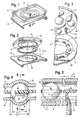
Figure 1 is a perspective view of a conventional swivel scat support, but having internal constructions features hidden from view; -
Figure 2 is an exploded perspective view of the embodiment ofFigure 1 , showing the internal construction features made in accordance with one embodiment of the present invention; -
Figure 3 is an enlarged and partial perspective view more clearly illustrating the preferred embodiment ofFigure 2 ; -
Figure 4 is an enlarged cross section taken along line 4-4 ofFigure 1 ; and -
Figure 5 is a cross section taken along line 5-5 ofFigure 4 and showing the manner in which the self cleaning function of the preferred embodiment is achieved. - With reference now to the drawings, a
swivel assembly 10 is shown having anupper plate 12 and alower plate 14. These plates support and contain a plurality ofbearings 16 and aretainer 18, so that theassembly 10 facilitates relative rotation between the twoplates assembly 10 to swivel easily. - Each of the
plates tracks bearings 16. In the prior art, the tracks arc typically sized so that the radius of the tracks generally match the radius of the bearings. In accordance with a preferred embodiment of the present invention and as shown inFigure 4 , thelower track 22 has a width "X" which is smaller than the diameter "Y" of thebearing 16. In other words, the radius of the track is less than the radius of the bearing. As a result, the bearing 16 rides on the shoulders oflower track 22 and is spaced from the bottom of the track. By way of example, the width of the lower track or ball race may be 305 millimeters, with a bearing diameter 9/16 inches (14.2875mm). - In the preferred embodiment illustrated in the drawings, the
lower track 22 is also provided with an opening or, preferably, a plurality ofopenings 24. Preferably the openings are positioned at or near the bottom oftrack 22 so as not to interfere with the rolling action of the bearings as they move relative tolower plate 14. The openings may be circular or rectangular and are, preferably, elongated slots. Again, by way of example, the openings may be 3 x 10 millimeter slots, with each positioned at equally spaced intervals aroundtrack 22. Preferably, twelve equally spaced openings are employed. - In addition to the plates and bearings, the
swivel assembly 10 also includes aretainer 18 having a plurality ofapertures 26 sized to receive thebearings 16 and maintain the bearings in fixed spaced relation around the circumference oftracks retainer 18 is in the form of an annular and generally flat ring and has one or more dependingwipers 28. Most preferably, theretainer 18 has a plurality of wipers spaced around its circumference, eachwiper 28 having a size and configuration so that it closely conforms to the internal configuration oflower track 22. - The operation of the swivel assembly made in accordance with the illustrated preferred embodiment is illustrated generally in
Figure 5 . As the seat swivels, theplates bearings 16 to roll as depicted by arrow "C" and since the bearings are rolling on thetrack 22, this causes the bearings to drive theretainer 18 and move it relative to both the upper and lower tracks. Importantly, since the retainer is moving relative to the lower track, thewipers 28 perform a sweeping action relative to the lower track, thereby directing dirt and debris that may have collected in the lower track into thelower track openings 24 and out of the track. This effectively self cleans thetrack 22 during the normal operation of the swivel and reduces the possibility that the swivel assembly will become less effective or fail over time. - Those of skill in the art will, understand and appreciate that various changes and modifications can be made to the preferred embodiments without departing from the spirit and teachings of the present invention. For example, the
tracks
Claims (5)
- A swivel seat assembly, comprising:a seat;a support for the seat including upper and lower swivel plates each having an annular recess; the lower plate recess having one or more openings;a plurality of ball bearings disposed between the upper and lower plate recesses, each of the ball bearings having a diameter greater than the width of the lower plate recess so that each of the ball bearings is spaced from the bottom of the recess; andan annular retainer having a plurality of apertures and a wiper, with each aperture sized to receive one of the ball bearings and the wiper configured to direct debris from the lower plate recess into the one or more openings of said lower plate recess.
- The swivel seat assembly of Claim 1 wherein the apertures in said retainer are equally spaced around the retainer and a plurality of wipers are employed with a wiper located between each pair of apertures.
- The swivel plate assembly of Claim 1 or Claim 2 wherein each of the plate recesses is generally semicircular in cross section and the wiper has a generally semicircular shape.
- The swivel plate assembly as claimed in any of Claims 1-3 wherein the lower plate recess has a plurality of openings and each opening comprises an elongated slot.
- The swivel plate assembly of Claim 4 wherein each of the slots is positioned at the bottom of the lower plate recess.
Applications Claiming Priority (1)
| Application Number | Priority Date | Filing Date | Title |
|---|---|---|---|
| US11/705,607 US20080191534A1 (en) | 2007-02-12 | 2007-02-12 | Self cleaning swivel seat assembly |
Publications (1)
| Publication Number | Publication Date |
|---|---|
| EP1955890A2 true EP1955890A2 (en) | 2008-08-13 |
Family
ID=39322531
Family Applications (1)
| Application Number | Title | Priority Date | Filing Date |
|---|---|---|---|
| EP08002105A Withdrawn EP1955890A2 (en) | 2007-02-12 | 2008-02-05 | Self-cleaning swivel assembly |
Country Status (5)
| Country | Link |
|---|---|
| US (1) | US20080191534A1 (en) |
| EP (1) | EP1955890A2 (en) |
| JP (1) | JP2008213827A (en) |
| CN (1) | CN101243921A (en) |
| CA (1) | CA2618760A1 (en) |
Families Citing this family (8)
| Publication number | Priority date | Publication date | Assignee | Title |
|---|---|---|---|---|
| CN202923422U (en) * | 2012-08-14 | 2013-05-08 | 常州华阳万联汽车附件有限公司 | Car seat rotating device |
| DE102012112523B4 (en) * | 2012-12-18 | 2020-11-12 | Grammer Aktiengesellschaft | Commercial vehicle seat with rotatable seat part |
| CN105634391A (en) * | 2014-10-31 | 2016-06-01 | 比亚迪股份有限公司 | Solar cell support and solar cell array |
| CN105634390B (en) * | 2014-10-31 | 2018-11-09 | 比亚迪股份有限公司 | Solar battery bracket and solar cell array |
| WO2019135358A1 (en) | 2018-01-05 | 2019-07-11 | パナソニックIpマネジメント株式会社 | Vehicle |
| US10292497B1 (en) | 2018-01-23 | 2019-05-21 | Toyota Motor Engineering & Manufacturing North America, Inc. | Perimeter supported seat assemblies and associated methods |
| CN109892887A (en) * | 2019-03-21 | 2019-06-18 | 东莞市宝城家具有限公司 | The townhouse chair that can be moved forward or retreat |
| CN117104091B (en) * | 2023-10-25 | 2024-01-23 | 今创集团股份有限公司 | Rotating device, driving mechanism and seat driving assembly |
Citations (5)
| Publication number | Priority date | Publication date | Assignee | Title |
|---|---|---|---|---|
| US5482354A (en) | 1989-12-04 | 1996-01-09 | Sears Manufacturing Company | Swivel seat, especially for vehicles |
| US5584460A (en) | 1995-03-31 | 1996-12-17 | Sears Manufacturing Co. | Adjustable seat apparatus and controls |
| US5599065A (en) | 1995-12-19 | 1997-02-04 | Sears Manufacturing Company | Seat swivel apparatus |
| US5720462A (en) | 1995-03-31 | 1998-02-24 | Sears Manufacturing Company | Rotatable and fore-aft slidable seat mount and controls |
| US6447065B1 (en) | 2000-07-19 | 2002-09-10 | Sears Manufacturing Company | Adjustable swivel assembly for seat suspensions |
Family Cites Families (6)
| Publication number | Priority date | Publication date | Assignee | Title |
|---|---|---|---|---|
| US1732113A (en) * | 1928-06-05 | 1929-10-15 | Peter C A Van Der Meer | Turntable |
| US2001999A (en) * | 1932-11-26 | 1935-05-21 | Brewer Titchener Corp | Seat adjuster |
| US3338622A (en) * | 1965-12-08 | 1967-08-29 | Chrysler Corp | Swivel seat for motor vehicle |
| GB1556378A (en) * | 1976-10-27 | 1979-11-21 | Skf Uk Ltd | Bearing cages |
| JPH074334Y2 (en) * | 1988-09-29 | 1995-02-01 | 日本精工株式会社 | Linear guide device with protector |
| US5779309A (en) * | 1997-09-02 | 1998-07-14 | Lu; Cheng-Ho | Swivel plate device |
-
2007
- 2007-02-12 US US11/705,607 patent/US20080191534A1/en not_active Abandoned
-
2008
- 2008-01-21 CA CA002618760A patent/CA2618760A1/en not_active Abandoned
- 2008-02-04 CN CN200810006245.XA patent/CN101243921A/en active Pending
- 2008-02-05 EP EP08002105A patent/EP1955890A2/en not_active Withdrawn
- 2008-02-12 JP JP2008030285A patent/JP2008213827A/en active Pending
Patent Citations (5)
| Publication number | Priority date | Publication date | Assignee | Title |
|---|---|---|---|---|
| US5482354A (en) | 1989-12-04 | 1996-01-09 | Sears Manufacturing Company | Swivel seat, especially for vehicles |
| US5584460A (en) | 1995-03-31 | 1996-12-17 | Sears Manufacturing Co. | Adjustable seat apparatus and controls |
| US5720462A (en) | 1995-03-31 | 1998-02-24 | Sears Manufacturing Company | Rotatable and fore-aft slidable seat mount and controls |
| US5599065A (en) | 1995-12-19 | 1997-02-04 | Sears Manufacturing Company | Seat swivel apparatus |
| US6447065B1 (en) | 2000-07-19 | 2002-09-10 | Sears Manufacturing Company | Adjustable swivel assembly for seat suspensions |
Also Published As
| Publication number | Publication date |
|---|---|
| US20080191534A1 (en) | 2008-08-14 |
| JP2008213827A (en) | 2008-09-18 |
| CA2618760A1 (en) | 2008-08-12 |
| CN101243921A (en) | 2008-08-20 |
Similar Documents
| Publication | Publication Date | Title |
|---|---|---|
| EP1955890A2 (en) | Self-cleaning swivel assembly | |
| EP0321757B1 (en) | Inner race of a clutch release mechanism | |
| EP2313283B1 (en) | Steering knuckle with pre-sealing | |
| US5829892A (en) | Center bearing bracket and support | |
| DE69809214T2 (en) | Device with a sensor, for fastening in an axle bearing unit for rail vehicles | |
| DE112010003791T5 (en) | Wheel bearing device for a vehicle | |
| DE2526436A1 (en) | WHEEL FOR FLOOR VEHICLES OR DGL. | |
| EP1786634A2 (en) | Wheel bearing arrangement comprising a radial-flange-side encoder | |
| US20090077766A1 (en) | Roller support assemblies | |
| DE102020002878B3 (en) | Wheel bearing device | |
| EP0925847A1 (en) | Starscreen | |
| DE10058935B4 (en) | Device for fastening a fan screw to a drive shaft | |
| EP1336052B1 (en) | Bearing for locating a steering shaft | |
| WO2008145456A1 (en) | Shock strut bearing and shock strut | |
| DE102008051065A1 (en) | Wheel bearing assembly with seal | |
| DE112010003444T5 (en) | Ball bearing device for steering column | |
| DE102004043351A1 (en) | roller bearing assembly | |
| DE112007000533T5 (en) | Bearing device for a wheel of a vehicle | |
| EP2084412A1 (en) | Wheel bearing arrangement for motor vehicles | |
| JPH09210056A (en) | Rolling bearing | |
| WO2004024504A1 (en) | Ratchet locking mechanism for a pivot bearing on an external vehicle mirror | |
| DE102006004274A1 (en) | Multi-row rolling bearing | |
| DE102013106191B4 (en) | Radwaschvorrichtung | |
| EP3538781A1 (en) | Wheel bearing arrangement for a motor vehicle | |
| DE3141073A1 (en) | ROLLER BEARING UNIT FOR DRIVED OR NON-DRIVED WHEELS OF VEHICLES OR THE LIKE |
Legal Events
| Date | Code | Title | Description |
|---|---|---|---|
| PUAI | Public reference made under article 153(3) epc to a published international application that has entered the european phase |
Free format text: ORIGINAL CODE: 0009012 |
|
| AK | Designated contracting states |
Kind code of ref document: A2 Designated state(s): AT BE BG CH CY CZ DE DK EE ES FI FR GB GR HR HU IE IS IT LI LT LU LV MC MT NL NO PL PT RO SE SI SK TR |
|
| AX | Request for extension of the european patent |
Extension state: AL BA MK RS |
|
| STAA | Information on the status of an ep patent application or granted ep patent |
Free format text: STATUS: THE APPLICATION HAS BEEN WITHDRAWN |
|
| 18W | Application withdrawn |
Effective date: 20090303 |