EP1955852A1 - Fluid container,recycling method of fluid container, and sealing method of fluid container - Google Patents
Fluid container,recycling method of fluid container, and sealing method of fluid container Download PDFInfo
- Publication number
- EP1955852A1 EP1955852A1 EP08151182A EP08151182A EP1955852A1 EP 1955852 A1 EP1955852 A1 EP 1955852A1 EP 08151182 A EP08151182 A EP 08151182A EP 08151182 A EP08151182 A EP 08151182A EP 1955852 A1 EP1955852 A1 EP 1955852A1
- Authority
- EP
- European Patent Office
- Prior art keywords
- film
- ink
- fluid container
- opening
- sealing member
- Prior art date
- Legal status (The legal status is an assumption and is not a legal conclusion. Google has not performed a legal analysis and makes no representation as to the accuracy of the status listed.)
- Granted
Links
- 238000007789 sealing Methods 0.000 title claims abstract description 59
- 239000012530 fluid Substances 0.000 title claims abstract description 57
- 238000000034 method Methods 0.000 title claims abstract description 30
- 238000004064 recycling Methods 0.000 title claims description 6
- 239000010408 film Substances 0.000 claims abstract description 195
- 239000013039 cover film Substances 0.000 claims abstract description 66
- 238000010438 heat treatment Methods 0.000 claims abstract description 20
- 229920000139 polyethylene terephthalate Polymers 0.000 claims description 7
- 239000005020 polyethylene terephthalate Substances 0.000 claims description 7
- 229920000098 polyolefin Polymers 0.000 claims description 7
- -1 polyethylene terephthalate Polymers 0.000 claims description 6
- 238000010030 laminating Methods 0.000 claims description 4
- 150000002148 esters Chemical class 0.000 claims description 3
- 238000003825 pressing Methods 0.000 description 13
- 238000003466 welding Methods 0.000 description 9
- 239000000463 material Substances 0.000 description 8
- 239000000758 substrate Substances 0.000 description 6
- 239000012634 fragment Substances 0.000 description 5
- 238000002844 melting Methods 0.000 description 5
- 230000008018 melting Effects 0.000 description 5
- 229920000728 polyester Polymers 0.000 description 5
- 230000008901 benefit Effects 0.000 description 4
- 238000004891 communication Methods 0.000 description 4
- 229920001971 elastomer Polymers 0.000 description 4
- 230000001070 adhesive effect Effects 0.000 description 3
- 230000007423 decrease Effects 0.000 description 3
- 230000009969 flowable effect Effects 0.000 description 3
- 239000007788 liquid Substances 0.000 description 3
- 230000000149 penetrating effect Effects 0.000 description 3
- 239000004677 Nylon Substances 0.000 description 2
- 239000004743 Polypropylene Substances 0.000 description 2
- 239000000853 adhesive Substances 0.000 description 2
- 239000002390 adhesive tape Substances 0.000 description 2
- 230000015572 biosynthetic process Effects 0.000 description 2
- 230000000903 blocking effect Effects 0.000 description 2
- 230000007246 mechanism Effects 0.000 description 2
- 239000000155 melt Substances 0.000 description 2
- 239000002184 metal Substances 0.000 description 2
- 229920001778 nylon Polymers 0.000 description 2
- 229920001155 polypropylene Polymers 0.000 description 2
- 238000004321 preservation Methods 0.000 description 2
- 239000004065 semiconductor Substances 0.000 description 2
- JOYRKODLDBILNP-UHFFFAOYSA-N Ethyl urethane Chemical compound CCOC(N)=O JOYRKODLDBILNP-UHFFFAOYSA-N 0.000 description 1
- 239000003086 colorant Substances 0.000 description 1
- 239000000806 elastomer Substances 0.000 description 1
- 230000001747 exhibiting effect Effects 0.000 description 1
- 238000013467 fragmentation Methods 0.000 description 1
- 238000006062 fragmentation reaction Methods 0.000 description 1
- 239000003049 inorganic solvent Substances 0.000 description 1
- 229910001867 inorganic solvent Inorganic materials 0.000 description 1
- 238000003780 insertion Methods 0.000 description 1
- 230000037431 insertion Effects 0.000 description 1
- 239000003960 organic solvent Substances 0.000 description 1
- 239000002245 particle Substances 0.000 description 1
- 230000035515 penetration Effects 0.000 description 1
- 239000004033 plastic Substances 0.000 description 1
- 229920003023 plastic Polymers 0.000 description 1
- 239000000843 powder Substances 0.000 description 1
- 229920005989 resin Polymers 0.000 description 1
- 239000011347 resin Substances 0.000 description 1
- 229920002379 silicone rubber Polymers 0.000 description 1
- 239000004945 silicone rubber Substances 0.000 description 1
- 239000007787 solid Substances 0.000 description 1
- 239000000243 solution Substances 0.000 description 1
- 229920003002 synthetic resin Polymers 0.000 description 1
- 239000000057 synthetic resin Substances 0.000 description 1
Images



Classifications
-
- B—PERFORMING OPERATIONS; TRANSPORTING
- B41—PRINTING; LINING MACHINES; TYPEWRITERS; STAMPS
- B41J—TYPEWRITERS; SELECTIVE PRINTING MECHANISMS, i.e. MECHANISMS PRINTING OTHERWISE THAN FROM A FORME; CORRECTION OF TYPOGRAPHICAL ERRORS
- B41J2/00—Typewriters or selective printing mechanisms characterised by the printing or marking process for which they are designed
- B41J2/005—Typewriters or selective printing mechanisms characterised by the printing or marking process for which they are designed characterised by bringing liquid or particles selectively into contact with a printing material
- B41J2/01—Ink jet
- B41J2/17—Ink jet characterised by ink handling
- B41J2/175—Ink supply systems ; Circuit parts therefor
- B41J2/17503—Ink cartridges
- B41J2/17536—Protection of cartridges or parts thereof, e.g. tape
Definitions
- the present invention relates to a fluid container containing fluid, a recycling method of a fluid container by refilling a used fluid contained with fluid, and a sealing method of a fluid container.
- An ink cartridge removably mounted in an inkjet printer (hereinafter, referred to as a printer), which is a type of fluid ejection apparatus, for example, is known as a fluid container containing fluid.
- the ink cartridge includes a container body having a substantially flat box-like shape.
- An ink chamber is defined in the container body and contains ink as the fluid.
- An ink inlet hole is formed in a lower surface of the container body. Ink is initially introduced into the ink chamber through the ink inlet hole.
- a film is applied to the lower surface of the container body to cover the ink inlet hole, thus suppressing leakage of the ink through the ink inlet hole.
- Japanese Utility Model No. 3118670 discloses a technique by which a used ink cartridge is recycled as a reusable ink cartridge by refilling the container body with ink. This addresses to efficient use of resources and preservation of environments.
- a film sealing an ink inlet hole is peeled off before an ink cartridge is refilled with ink.
- the ink is then charged into an ink chamber through the ink inlet hole.
- the ink inlet hole is sealed with a rubber stopper and a welding film is mounted on the body of the container in such a manner as to cover the ink inlet hole.
- the welding film is then thermally welded to a portion of the surface of the container body encompassing the ink inlet hole. This seals the ink inlet hole.
- the ink inlet hole is blocked by the rubber stopper and the welding film is thermally welded to the portion of the surface of the container body encompassing the ink inlet hole.
- the method involves blocking the ink inlet hole using the rubber stopper and thermally welding the film after refilling the ink cartridge with the ink. This complicates the refilling of the ink cartridge and increases the number of components needed for sealing, thus raising the costs.
- an adhesive tape of polyester which is a thermally welding adhesive tape of plastic
- a polyester based film exhibits an improved thermal welding property, heat resistance of the film is low compared to a polyethylene terephthalate based film generally used as a sealing film of an ink cartridge. This decreases the reliability of the polyester based film.
- the low reliability of the polyester based film may lead to leakage of the ink from the ink chamber through the ink inlet hole.
- a method for sealing an opening to be sealed is provided.
- the opening to be sealed is one of a hole formed in a fluid container and a hole formed in a cover film welded or bonded to the fluid container in such a manner as to cover the hole of the fluid container.
- the method includes: preparing a sealing member, the sealing member being a laminated film formed by laminating a plurality of films including a first film and a second film, wherein the first film is meltable at a predetermined heating temperature, and the second film is not meltable at the heating temperature and exhibits an improved heat resistance compared to the first film, the first film forming one of outermost layers of the laminated film, the second film forming the other of the outermost layers; placing the sealing member on the fluid container with the first film facing the fluid container in such a manner that the sealing member covers the opening to be sealed; and sealing the opening to be sealed with the sealing member by heating the sealing member from the second film side to melt the first film.
- a method for recycling a fluid container includes: refilling a used fluid container through an opening to be sealed with a fluid, the opening to be sealed being one of a hole formed in the fluid container and a hole formed in a cover film welded or bonded to the fluid container in such a manner as to cover the hole: preparing a sealing member, the sealing member being a laminated film formed by laminating a plurality of films including a first film and a second film, wherein the first film is meltable at a predetermined heating temperature, and the second film is not meltable at the heating temperature and exhibits an improved heat resistance compared to the first film, the first film forming one of outermost layers of the laminated film, the second film forming the other of the outermost layers; placing the sealing member on the fluid container with the sealing member facing the fluid container in such a manner that the sealing member covers the opening to be sealed; and sealing the opening to be sealed with the sealing member by heating the sealing member from second film side to
- a fluid container recycled using the method for recycling the fluid container according to the above second aspect of the present invention is provided.
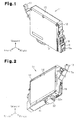
- Fig. 1 is a front perspective view showing an ink cartridge according to one embodiment of the present invention
- Fig. 2 is a rear perspective view showing the ink cartridge of Fig. 1 ;
- Fig. 3 is a partially exploded front perspective view showing the ink cartridge of Fig. 1 ;
- Fig. 4 is a partially exploded front view showing the ink cartridge of Fig. 1 ;
- Fig. 5A is a plan view showing a piercing jig
- Fig. 5B is a cross-sectional view taken along line 5B-5B of Fig. 5A ;
- Fig. 5C is a cross-sectional view taken along line 5C-5C of Fig. 5A ;
- Fig. 5D is a plan view showing a blade body secured to the piercing jig of Fig. 5A ;
- Fig. 5E is a plan view showing a blade body of a modified embodiment
- Fig. 5F is a plan view showing a blade body of another modified embodiment
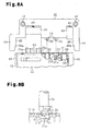
- Fig. 6A is a view illustrating a mounted state of a piercing jig in a piercing step
- Fig. 6B is a cross-sectional view showing a portion of the piercing jig and a portion of the ink cartridge when an opening is being formed in the ink cartridge;
- Fig. 7 is a view illustrating a state in which the ink cartridge is filled with ink through the opening.
- Fig. 8 is a view illustrating a sealing step.
- an ink cartridge 11, or a fluid container of the illustrated embodiment includes a container body 12, which is shaped substantially like a flat rectangular box and formed of synthetic resin, which is, for example, polypropylene (PP).
- a container body 12 which is shaped substantially like a flat rectangular box and formed of synthetic resin, which is, for example, polypropylene (PP).
- PP polypropylene
- an opening 12a is formed in a front surface of the container body 12.
- a film member (not shown), which is formed of thermally adhesive material, is welded to the container body 12 to substantially cover the entire opening 12a.
- a lid body 13 is detachably attached to the container body 12 from outside the film member (the side corresponding to the front surface) in such a manner that the opening 12a is shielded.
- a guide projection 16 extending in the up-and-down direction projects from a lower portion of a left surface of the container body 12.
- a printer which is a type of fluid ejection apparatus
- the guide projection 16 is received in a guide recess (not shown) formed in the cartridge holder. This guides the ink cartridge 11 when the ink cartridge 11 is mounted in the cartridge holder.
- an elastically deformable engagement lever 17 which projects diagonally to the upper left, is arranged at a position above the guide projection 16 on the left surface of the container body 12.
- An engagement piece 17a which extends horizontally (in the front-and-rear direction), projects substantially from the longitudinal center of the engagement lever 17 on a surface of the engagement lever 17.
- a substrate unit 18 is secured to a lower portion of a right surface of the container body 12.
- a circuit substrate 19 on which a semiconductor memory device is mounted is arranged on a surface of the substrate unit 18.
- the semiconductor memory device of the circuit substrate 19 stores various information regarding the ink cartridge 11 (for example, information regarding ink colors and ink containing amounts).
- Terminals 19a are provided on the surface of the circuit substrate 19.
- the terminals 19a contact connection terminals formed in the cartridge holder. This transfers various information between the circuit substrate 19 and a control device (not shown) of the printer.
- a rectangular opening 20, a first ink inlet hole 21 having a circular shape, a second ink inlet hole 22 having a circular shape, and an ink supply port 23 having a circular shape are formed in a lower surface of the container body 12 and arranged in this order from the right end to the left end of the lower surface.
- the ink supply port 23 has a pair of guide walls 23a each having a substantial U shape, which are provided at the right end and the left end of the ink supply port 23.
- the interior of the opening 20 defines an atmospheric air communication chamber 24, which configures a portion of an atmospheric air communication passage.
- the atmospheric air communication chamber 24 communicates with the exterior of the container body 12, or the atmospheric air, through a non-illustrated atmospheric air exposure port.
- the atmospheric air communication chamber 24 accommodates a coil spring 25, a valve body 26, and a valve support member 27 in this order from inward to outward.
- a rib 28 defines an upper ink chamber 29 and a lower ink chamber 30 in the container body 12.
- the first ink inlet hole 21 communicates with the upper ink chamber 29 and the lower ink chamber 30 through a narrow passage 21a and a narrow ink inlet port 21b, which are formed in the container body 12.
- the second ink inlet hole 22 communicates directly with the lower ink chamber 30.
- ink is introduced through the ink inlet holes 21, 22.
- the first and second ink inlet holes 21, 22 are sealed by a cover film 31 along with the opening 20.
- the cover film 31 is formed by a polyethylene terephthalate (PET) based film or a nylon (NY) based film exhibiting improved heat resistance.
- an ink supply needle (not shown) provided in the cartridge holder is inserted into the ink supply port 23.
- the ink supply port 23 is sealed by a film member 32 before the ink cartridge 11 is mounted in the cartridge holder.
- the film member 32 may be either removed from the ink cartridge 11 before mounting of the ink cartridge 11 in the cartridge holder or penetrated by the ink supply needle of the cartridge holder when the ink cartridge 11 is secured to the cartridge holder.
- the interior of the ink supply port 23 accommodates an annular seal member 33 formed of elastomer or the like, a supply valve 34, and a coil spring 35.
- the seal member 33 allows penetration of the ink supply needle of the cartridge holder into the ink supply port 23.
- the supply valve 34 is brought into contact with the seal member 33.
- the coil spring 35 urges the supply valve 34 toward the seal member 33.
- the supply valve 34 is urged by the coil spring 35 to be pressed against the seal member 33, thus closing the ink supply port 23. This constantly prevents the ink from flowing from the interior of the container body 12 to the exterior through the ink supply port 23.
- the ink supply needle of the cartridge holder presses the supply valve 34 inwardly in the ink supply port 23 against the urging force of the coil spring 35.
- the supply valve 34 is thus separated from the seal member 33. This opens the ink supply port 23, allowing the ink to flow from the interior of the container body 12 to the exterior through the ink supply port 23.
- the printer consumes the ink until the ink is used up.
- the used ink cartridge 11 is removed from the cartridge holder and replaced by a new ink cartridge 11.
- the used ink cartridge 11 is then refilled with ink and recycled as a reusable ink cartridge without being discarded. This contributes to efficient use of resources and preservation of environments.
- an opening 61 through which ink is introduced is formed in the cover film 31 using a piercing jig 40.
- the piercing jig 40 will hereafter be explained with reference to Figs. 5A to 5F .
- the piercing jig 40 of the illustrated embodiment has a base body 41 and a pair of joint plates 43.
- the base body 41 has a substantial U shape as viewed from the side.
- the joint plates 43 are connected to opposing front and rear surfaces of the base body 41 with bolts 42.
- the thickness L1 of the base body 41 (see Fig. 5C ) is substantially equal to the thickness of the ink cartridge 11.
- the base body 41 has a pair of legs 44, which extend downward from the opposing left and right ends of the base body 41.
- the interval L2 between the legs 44 is substantially equal to the dimension of the ink cartridge 11 in the left-and-right direction.
- a pair of opposing inner surfaces 45 of the left and right legs 44 function as guide portions that are slidable on the left and right surfaces of the ink cartridge 11.
- a tapered surface 45a extends from the rear end of each of the inner surfaces 45 and inclines outwardly toward the distal end of the inner surface 45.
- a groove 45b is formed in the inner surface 45 of the left leg 44, as viewed in Fig. 5B . The groove 45b slidably receives the guide projection 16 projecting from the left surface of the ink cartridge 11.
- each of the joint plates 43 is formed by a substantially rectangular plate.
- the dimension of each joint plate 43 in the left-and-right direction is substantially equal to the dimension of the base body 41 in the left-and-right direction.
- the dimension of the joint plate 43 in the up-and-down direction is substantially equal to the dimension of the base body 41 (including the legs 44) in the up-and-down direction.
- Opposing inner surfaces 46 of the joint plates 43 function as guide portions that are slidable on the front surface and the rear surface of the ink cartridge 11.
- a tapered surface 46a extends from the lower end of each of the inner surfaces 46 and is inclined outwardly toward the distal end of the associated one of the joint plates 43.
- cutouts 47 each having a rectangular shape as viewed from the side are formed near the left and right ends of the lower surface of the base body 41, which are arranged between the two legs 44.
- the dimension of the left cutout 47 as viewed in Fig. 5B in the left-and-right direction is substantially equal to the interval between the two guide walls 23a, which are provided in the ink supply port 23 of the ink cartridge 11.
- a block 48, or a movable member having a parallelepiped shape, is slidably received in each of the cutouts 47.
- Each of the blocks 48 is selectively projected from and retracted into the corresponding one of the cutouts 47.
- the base body 41 has a pair of bolts 49, which extend from the side corresponding to the upper surface of the base body 41 into the corresponding cutouts 47.
- Each of the bolts 49 is rotatably supported by the base body 41.
- the base body 41 also has a pair of bolts 50, which extend from the sides corresponding to the left and right surfaces of the base body 41 into the corresponding cutouts 47.
- Each of the bolts 50 is rotatably supported by the base body 41.
- An external thread portion 51 is formed in a distal portion of each bolt 49.
- An internal thread bore 52 is formed in the block 48 received in the corresponding cutout 47.
- Each of the external thread portions 51 is threaded with the associated one of the internal thread bores 52.
- the distal surface of each bolt 50 contacts a side surface of the block 48 received in the corresponding cutout 47. The bolts 50 thus restrict movement of the blocks 48 received in the corresponding cutouts 47.
- the blocks 48 are moved in the cutouts 47 in the up-and-down direction.
- the blocks 48 are moved in directions in which the blocks 48 are retracted into the corresponding cutouts 47 (in an upward direction as viewed in Fig. 5B ).
- the blocks 48 are moved in directions in which the blocks 48 are projected from the corresponding cutouts 47 (in a downward direction as viewed in Fig. 5B ).
- a pair of circular bores 53 which correspond to the first ink inlet hole 21 and the second ink inlet hole 22 of the ink cartridge 11, are formed in the lower surface of the base body 41 between the cutouts 47.
- Each of the circular bores 53 accommodates a blade body 54.
- Each of the blade bodies 54 has a columnar body and a distal portion. The diameter of the columnar body is slightly smaller than the inner diameter of each circular bore 53. The distal portion has a conical shape as viewed from the side.
- Each blade body 54 is rotatably supported in the corresponding circular bore 53. In this state, the distal portion of the blade body 54 projects from the circular bore 53.
- each blade body 54 has four blade portions 55 formed in the distal portion of each blade body 54.
- the blade portions 55 extend radially from the axis of the blade body 54, as viewed in the axial direction of the blade body 54 from the side corresponding to the distal end of the blade body 54.
- the four blade portions 55 are spaced at equal angular intervals (in the illustrated embodiment, at 90 degrees).
- Each of the blade portions 55 extends toward the proximal end of the blade body 54 as the blade portion 55 radially separates from the axis of the blade body 54.
- the distal portion of the blade body 54 has a conical shape the top of which coincides with the crossing points of the blade portions 55.
- the base body 41 has a pair of bolts 56, which extend from the side corresponding to the top surface of the base body 41 into the corresponding circular bores 53.
- Each of the bolts 56 is rotatably supported by the base body 41.
- One of the joint plates 43 has a pair of pressing screws 57, which extend from outside the joint plate 43 into the corresponding circular bores 53. The pressing screws 57 configure an adjustment mechanism.
- An external thread portion 58 is formed at the distal portion of each of the bolts 56 and threaded with an internal thread bore 59 formed in the proximal portion of the blade body 54 received in the corresponding circular bore 53.
- the distal surface of each of the pressing screws 57 is pressed against a side surface of the blade body 54 in the corresponding one of the circular bores 53. This restricts rotation of the blade body 54.
- each of the bolts 56 and the associated one of the blade bodies 54 which are integrated through engagement between the external thread portion 58 and the internal thread bore 59, are lowered by the distance corresponding to the amount by which the head of the bolt 56 has been raised. This changes the projection amount of each blade body 54 from the lower surface of the base body 41.
- the used ink cartridge 11 is placed with the lower surface of the ink cartridge 11 facing upward, with reference to Fig. 6A .
- the film member 32 has been separated from the ink supply port 23 by this time.
- the piercing jig 40 is arranged in such a manner that the lower surface of the piercing jig 40 opposes the lower surface of the ink cartridge 11, which faces upward, and that the two blade portions 55 oppose the covering areas of the cover film 31 with respect to the ink inlet holes 21, 22 in the up-and-down direction.
- each blade body 54 and the position of each block 48 are adjusted in advance to ensure that the angular positions of the blade portions 55 of the blade body 54 coincide with desirable positions in cutting of the cover film 31 and prevent the blade portions 55 from entering the ink inlet holes 21, 22 by an excessive amount when the piercing jig 40 is brought close to the ink cartridge 11 and the blade portions 55 of the two blade bodies 54 penetrate the cover film 31.
- the amount by which the blade bodies 54 project into the corresponding ink inlet holes 21, 22 may be adjusted by rotating the bolts 56 and the pressing screws 57 alternately to change the projecting amounts of the blade bodies 54 from the lower surface of the base body 41.
- the piercing jig 40 is brought closer to the ink cartridge 11. This causes the inner surfaces 45 of the legs 44 of the piercing jig 40 to slide on the left surface and the right surface of the ink cartridge 11 and the inner surfaces 46 of the joint plates 43 to slide on the front surface and the rear surface of the ink cartridge 11. Further, the inner surface of the left cutout 47 slides on the guide walls 23a of the ink supply port 23 of the ink cartridge 11 to adjust the movement direction of the cutout 47 with respect to the ink supply port 23.
- the blade portions 55 of the two blade bodies 54 penetrate the covering areas of the cover film 31 that covers the ink inlet holes 21, 22. This causes the blade portions 55 to form cross-shaped cuts in the cover film 31. Each of the cuts extends radially from the point corresponding to the center of the corresponding one of the ink inlet holes 21, 22.
- Each of the cross-shaped cuts forms four cut pieces 60 that are identically shaped and supported in a cantilever manner.
- the cut pieces 60 thus hang down in the corresponding ink inlet hole 21, 22 separately from one another in radial directions.
- an opening 61 is formed in the covering area of the cover film 31 that covers each ink inlet hole 21, 22.
- the blocks 48 of the piercing jig 40 contact the lower surface of the ink cartridge 11 that faces upward and the distal end of the ink supply port 23. This suppresses further proceeding of the blade bodies 54 into the ink inlet holes 21, 22. That is, in the illustrated embodiment, each block 48 serving as the movable member functions as a restricting portion that restricts proceeding of the blade portions 55 of the blade bodies 54 into the ink inlet holes 21, 22 by excessive amounts.
- an ink introduction nozzle N serving as a filling device shown in Fig. 7 is inserted into each of the ink inlet holes 21, 22 through the associated one of the openings 61.
- Ink refill is thus supplied to the ink chambers 29, 30, which communicate with the corresponding ink inlet holes 21, 22.
- the openings 61 which have been provided for ink refilling, are sealed by a laminated film 70, which is a sealing member. In this manner, the used ink cartridge 11 is recycled as a reusable ink cartridge 11.
- the laminated film 70 is mounted on the cover film 31 in such a manner as to cover the openings 61 extending through the cover film 31.
- the laminated film 70 has a two-layer structure including a first film 71 and a second film 72.
- the first film 71 is molten when heated at a predetermined temperature.
- the second film 72 cannot be molten at the melting temperature of the first film 71.
- the second film 72 has an improved heat resistance compared to the first film 71.
- the first film 71 forms the outermost layer at one side of the layering directions of the films 71, 72 and the second film 72 forms the outermost layer at the other side.
- the laminated film 70 is placed on the container body 12.
- the first film 71 is thus opposed to the container body 12 while maintained in contact with the cover film 31.
- the first film 71 is heated to be welded to the cover film 31.
- the second film 72 is arranged at an outer side, the second film 72, which has the improved heat resistance, maintains sealing by the laminated film 70.
- a polyolefin (PO) based film or an ester based film or an easy peel open (EPO) film may be employed as the first film 71. If the EPO film is used, the laminated film 70 is bonded to the cover film 31 through welding of the EPO film. Afterward, the EPO film may be easily peeled off the cover film 31 to expose the openings 61 when necessary.
- PO polyolefin
- EPO easy peel open
- the second film 72 is formed by a polyethylene terephthalate (PET) based film that does not melt at the temperature at which the polyolefin (PO) based film melts, and exhibits enhanced heat resistance compared to the PO based film.
- the thickness of the first film 71 which is layered with the second film 72, is set to 20 to 60 ⁇ m, and, preferably, to 40 ⁇ m. By setting the thickness of the first film 71 to 20 ⁇ m or greater, formation of a gap between the second film 72 and the cover film 31 is prevented even if the bonding surface of the second film 72 with respect to the first film 71 is uneven. By setting the thickness of the first film 71 to 60 ⁇ m or less, the thickness of the first film 71 is prevented from becoming excessively great, which increases the cost and decreases heat conductivity of the first film 71 when the first film 71 is heated.
- a heater 73 serving as a sealing device is lowered toward the laminated film 70 from above the laminated film 70 as shown in Fig. 8 .
- the heater 73 is heated to a predetermined temperature that melts the first film 71 of the laminated film 70 but does not melt the second film 72.
- the heater 73 is shaped as a block having a flat pressing surface that contacts the surface of the laminated film 70 (the surface of the second film 72) in a surface contact manner.
- the laminated film 70 By melting the first film 71 through heating by the heater 73, the laminated film 70 is firmly welded on the cover film 31.
- the laminated film 70 thus covers the openings 61 formed in the cover film 31 to seal the openings 61.
- the heater 73 is raised from the position (the contact position) represented by the solid lines in Fig. 8 to the position (the standby position) represented by the double-dotted chain lines in the drawing. This ends the sealing step and, as a result, a recycled and reusable ink cartridge 11 is obtained.
- the illustrated embodiment has the following advantages.
- the openings 61 formed in the cover film 31 using the piercing jig 40 are provided by the cut pieces 60, which are formed by the cross-shaped cuts in the cover film 31.
- the cut pieces 60 hang down in the ink inlet holes 21, 22, thus preventing generating fragments of the cover film 31.
- This also prevents ink refill, which is introduced through the openings 61, from containing fragments. Clogging of a passage (which is, for example, the narrow passage 21a or the narrow ink inlet port 21b) of the recycled ink cartridge 11 is thus suppressed. As a result, the ink cartridge 11 is effectively recycled.
- the openings 61 are formed in the covering areas of the cover film 31 with respect to the ink inlet holes 21, 22.
- Each of the openings 61 has the center corresponding to the center of the corresponding one of the ink inlet holes 21, 22. This facilitates introduction of the ink refill trough the openings 61.
- the four uniform-sized cut pieces 60 are provided in the covering area of the cover film 31 with respect to each ink inlet hole 21, 22 and extend radially from the center of the covering area.
- the cut pieces 60 hang down in the corresponding ink inlet hole 21, 22 to provide the opening 61 with a desirable shape. This facilitates insertion of the ink introduction nozzles into the openings 61. Supply of ink refill is thus easily carried out.
- each blade body 54 of the piercing jig 40 are each shaped to extend toward the proximal end of the blade body 54 as the blade portions 55 radially separate from a point on the axis of the blade body 54.
- the crossing point of the blade portions 55 thus becomes sharp and causes the distal end of each blade body 54 to penetrate the cover film 31 sharply in piercing.
- the piercing jig 40 forms the openings 61 with the desirable shapes. As a result, the openings 61 are easily formed in the cover film 31 without rotating the blade bodies 54.
- the container body 12 contacts the blocks 48, each of which functions as the restricting portion, thus restricting excessive proceeding of the blade portions 55 of the blade bodies 54 into the ink inlet holes 21, 22 of the container body 12. This prevents the container body 12 from being damaged the blade portions 55 that proceed into the ink inlet holes 21, 22 by excessive amounts. Also, the openings 61 formed in each piercing operation are uniformly sized.
- the inner surfaces 45 of the legs 44 and the inner surfaces 46 of the joint plates 43 of the piercing jig 40 function as guide portions that adjust the penetrating direction of each blade body 54 with respect to the cover film 31 along a direction perpendicular to the cover film 31.
- the blade portions 55 of each blade body 54 are guided constantly to the same positions in the covering area of the cover film 31 with respect to the corresponding ink inlet hole 21, 22.
- the openings 61 provided in each piercing operation are located at the constant positions.
- the first film 71 of the laminated film 70 is molten through heating and thus welded on the cover film 31. Further, since the second film 72 is heat resistant, the laminated film 70 ensures improved sealing performance. This provides the ink cartridge 11 with the enhanced sealing performance.
- the laminated film 70 may be removed from the cover film 31 when necessary even after the laminated film 70 is welded on the cover film 31.
- the thickness of the first film 71 is 20 to 60 ⁇ m.
- the first film 71 is reliably welded on the cover film 31 at the annular areas around the circumferences of the ink inlet holes 21, 22 through heating.
- the laminated film 70 thus exerts improved sealing performance.
- the first film 71 is heated both at the annular areas around the circumferences of the ink inlet holes 21, 22 and the covered areas of the ink inlet holes 21, 22, which are the interiors of the annular areas. This suppresses variation of strength in different areas and provides uniform sealing performance.
- each blade body 54 of the piercing jig 40 may include three blade portions 55 extending radially from a point on the axis of the blade body 54.
- the blade body 54 may include eight blade portions 55 extending radially from the point on the axis of the blade body 54.
- each blade body 54 may be configured in any suitable manner as long as the blade body 54 includes at least three blade portions 55 extending radially from a point corresponding to the distal end of the blade body 54.
- each blade body 54 which extend radially, may be spaced not at equal angular intervals but at unequal angular intervals about the axis of the blade body 54.
- each blade body 54 may extend radially on a plane perpendicular to the axis of the blade body 54 at distal of blade body 54.
- the inner surfaces 45 of the legs 44 and the inner surfaces 46 of the joint plates 43 of the piercing jig 40 do not necessarily have to slide on the corresponding side surfaces of the ink cartridge 11 in piercing. That is, the piercing jig 40 does not necessarily have to guide the ink cartridge 11.
- the blade bodies 54 may be fixed to the base body 41 so that the angular positions of the blade bodies 54 in the rotational direction cannot be changed.
- the piercing jig 40 does not necessarily have to include the cutouts 47 or the blocks 48.
- the lower surface of the base body 41 may either directly contact or be maintained spaced from a portion of the container body 12 of the ink cartridge 11.
- Each blade body 54 may be formed by a blade body having a conical distal end.
- the openings 61 are formed by passing the blade body through the cover film 31 from the distal end of the blade body.
- the piercing jig 40 may be a piercing jig having a blade body shaped like a punch.
- the piercing jig 40 may be conical or shaped like a pyramid.
- the openings 61 are formed in the cover film 31 without generating fragments of the cover film 31.
- Each blade body 54 of the piercing jig 40 may be configured in any suitable manner as long as the blade body 54 provides the cut pieces 60 that are supported in a cantilever manner by penetrating the cover film 31 by the distal end of the blade body 54.
- the blade body 54 may have a blade portion that is formed at the distal end of the blade body 54 and provides a U-shaped, C-shaped, or H-shaped cut in the cover film 31.
- Each opening 61 is thus shaped and sized in correspondence with the cut pieces provided by the blade portion. Also in this case, the openings 61 are formed without generating fragments of the cover film 31.
- the cover film 31 may be cut along the outline of the cut pieces 60 using a blade body such as a cutter knife.
- the heater 73 which heats the laminated film 70 while pressing the laminated film 70 against the cover film 31, may be shaped in any suitable form as long as the heater 73 is capable of heating the laminated film 70 and melting the first film 71.
- the heater 73 may heat solely the annular areas of the laminated film 70 around the circumferences of the two ink inlet holes 21, 22. In this case, the first film 71 is molten only at the annular areas.
- the thickness of the first film 71 of the laminated film 70 may be set to a value other than 40 ⁇ m as long as the value falls in the range of 20 to 60 ⁇ m.
- the first film 71 of the laminated film 70 may be a urethane based film or a bonding film with an adhesive property.
- the laminated film 70 may have a three-layer structure including an additional film arranged between the first film 71 and the second film 72. That is, the laminated film 70 may be configured in any suitable manner as long as the outermost layer that contacts the cover film 31 is the first film 71 and the opposing outermost layer is the second film 72.
- the openings 61 which are formed in the cover film 31 of the used ink cartridge 11 to be refilled with the ink, are formed as openings to be sealed.
- the ink inlet holes 21, 22, for example, of the ink cartridge 11 that has been refilled with the ink may be formed as openings that are to be sealed. In this case, the ink inlet holes 21, 22 are sealed by the laminated film 70.
- the sealing member that seals the openings 61, which are formed in the cover film 31 of the used ink cartridge 11 to be refilled with the ink, does not necessarily have to be the laminated film 70 that is heated to be welded on the cover film 31. That is, the sealing member may be a sealing stopper made of various materials including silicone rubber.
- the fluid container is embodied by the ink cartridge 11.
- the fluid container may be a fluid container that contains fluid other than ink (such as liquid, liquefied material containing particles of functional material that are dispersed in or mixed with liquid, or flowable material such as gel, or a solid that is flowable and ejectable as fluid).
- the "fluid” herein does not include fluid formed solely by gas.
- the "fluid” includes, for example, liquid (including inorganic solvents, organic solvents, solutions, liquefied resin, and liquefied metal (molten metal)), liquefied materials, flowable materials, and powder particulates.
Landscapes
- Ink Jet (AREA)
- Packging For Living Organisms, Food Or Medicinal Products That Are Sensitive To Environmental Conditiond (AREA)
- Making Paper Articles (AREA)
- Closing Of Containers (AREA)
Abstract
Description
- This application is based upon and claims the benefit of priority from prior Japanese Patent Application No.
2007-027908, filed on February 7, 2007 - The present invention relates to a fluid container containing fluid, a recycling method of a fluid container by refilling a used fluid contained with fluid, and a sealing method of a fluid container.
- An ink cartridge removably mounted in an inkjet printer (hereinafter, referred to as a printer), which is a type of fluid ejection apparatus, for example, is known as a fluid container containing fluid. The ink cartridge includes a container body having a substantially flat box-like shape. An ink chamber is defined in the container body and contains ink as the fluid. An ink inlet hole is formed in a lower surface of the container body. Ink is initially introduced into the ink chamber through the ink inlet hole. A film is applied to the lower surface of the container body to cover the ink inlet hole, thus suppressing leakage of the ink through the ink inlet hole.
- As printer the ink in the ink cartridge mounted in the printer, the ink in the ink chamber decreases and is eventually used up. The used ink cartridge is replaced by a new ink cartridge. Even after the ink cartridge is removed from the printer, the container body of the ink cartridge is still usable for repeated cycles. Japanese Utility Model No.
3118670 - In the method described in Japanese Patent No.
3667749 - In this method, following supply of the ink refill, the ink inlet hole is blocked by the rubber stopper and the welding film is thermally welded to the portion of the surface of the container body encompassing the ink inlet hole. In other words, the method involves blocking the ink inlet hole using the rubber stopper and thermally welding the film after refilling the ink cartridge with the ink. This complicates the refilling of the ink cartridge and increases the number of components needed for sealing, thus raising the costs.
- Further, as the welding film, an adhesive tape of polyester, which is a thermally welding adhesive tape of plastic, is employed. Although a polyester based film exhibits an improved thermal welding property, heat resistance of the film is low compared to a polyethylene terephthalate based film generally used as a sealing film of an ink cartridge. This decreases the reliability of the polyester based film. Thus, if blocking the ink inlet hole using the robber stopper is omitted, or the ink inlet hole is only sealed by the polyester based film, to facilitate the sealing of the hole and reduce the number of necessary components and the costs, the low reliability of the polyester based film may lead to leakage of the ink from the ink chamber through the ink inlet hole.
- Accordingly, it is an objective of the present invention to reliably and easily seal an opening to be sealed through which fluid is introduced into a used fluid container.
- In order to achieve the foregoing objective and in accordance with a first aspect of the present invention, a method for sealing an opening to be sealed is provided. The opening to be sealed is one of a hole formed in a fluid container and a hole formed in a cover film welded or bonded to the fluid container in such a manner as to cover the hole of the fluid container. The method includes: preparing a sealing member, the sealing member being a laminated film formed by laminating a plurality of films including a first film and a second film, wherein the first film is meltable at a predetermined heating temperature, and the second film is not meltable at the heating temperature and exhibits an improved heat resistance compared to the first film, the first film forming one of outermost layers of the laminated film, the second film forming the other of the outermost layers; placing the sealing member on the fluid container with the first film facing the fluid container in such a manner that the sealing member covers the opening to be sealed; and sealing the opening to be sealed with the sealing member by heating the sealing member from the second film side to melt the first film.
- In accordance with a second aspect of the present invention, a method for recycling a fluid container is provided. The method includes: refilling a used fluid container through an opening to be sealed with a fluid, the opening to be sealed being one of a hole formed in the fluid container and a hole formed in a cover film welded or bonded to the fluid container in such a manner as to cover the hole: preparing a sealing member, the sealing member being a laminated film formed by laminating a plurality of films including a first film and a second film, wherein the first film is meltable at a predetermined heating temperature, and the second film is not meltable at the heating temperature and exhibits an improved heat resistance compared to the first film, the first film forming one of outermost layers of the laminated film, the second film forming the other of the outermost layers; placing the sealing member on the fluid container with the sealing member facing the fluid container in such a manner that the sealing member covers the opening to be sealed; and sealing the opening to be sealed with the sealing member by heating the sealing member from second film side to melt the first film.
- In accordance with a third aspect of the present invention, a fluid container recycled using the method for recycling the fluid container according to the above second aspect of the present invention is provided.
- Other aspects and advantages of the invention will become apparent from the following description, taken in conjunction with the accompanying drawings, illustrating by way of example the principles of the invention.
- The features of the present invention that are believed to be novel are set forth with particularity in the appended claims. The invention, together with objects and advantages thereof, may best be understood by reference to the following description of the presently preferred embodiments together with the accompanying drawings in which:
-
Fig. 1 is a front perspective view showing an ink cartridge according to one embodiment of the present invention; -
Fig. 2 is a rear perspective view showing the ink cartridge ofFig. 1 ; -
Fig. 3 is a partially exploded front perspective view showing the ink cartridge ofFig. 1 ; -
Fig. 4 is a partially exploded front view showing the ink cartridge ofFig. 1 ; -
Fig. 5A is a plan view showing a piercing jig; -
Fig. 5B is a cross-sectional view taken alongline 5B-5B ofFig. 5A ; -
Fig. 5C is a cross-sectional view taken along line 5C-5C ofFig. 5A ; -
Fig. 5D is a plan view showing a blade body secured to the piercing jig ofFig. 5A ; -
Fig. 5E is a plan view showing a blade body of a modified embodiment; -
Fig. 5F is a plan view showing a blade body of another modified embodiment; -
Fig. 6A is a view illustrating a mounted state of a piercing jig in a piercing step; -
Fig. 6B is a cross-sectional view showing a portion of the piercing jig and a portion of the ink cartridge when an opening is being formed in the ink cartridge; -
Fig. 7 is a view illustrating a state in which the ink cartridge is filled with ink through the opening; and -
Fig. 8 is a view illustrating a sealing step. - An embodiment of the present invention will now be described with reference to
Figs. 1 to 7 . In the following description, the "front-and-rear direction", the "left-and-right" direction, and the "up-and-down" direction are the directions indicated by the corresponding arrows inFigs. 1 to 4 . - As shown in
Figs. 1 to 4 , anink cartridge 11, or a fluid container of the illustrated embodiment, includes acontainer body 12, which is shaped substantially like a flat rectangular box and formed of synthetic resin, which is, for example, polypropylene (PP). With reference toFig. 4 , anopening 12a is formed in a front surface of thecontainer body 12. A film member (not shown), which is formed of thermally adhesive material, is welded to thecontainer body 12 to substantially cover theentire opening 12a. Alid body 13 is detachably attached to thecontainer body 12 from outside the film member (the side corresponding to the front surface) in such a manner that theopening 12a is shielded. Afilm member 14, which is formed of thermally adhesive material, is bonded to a rear surface of thecontainer body 12 to substantially cover the entire rear surface. Anelongated ID label 15, which represents the color of the ink, or the fluid, contained in theink cartridge 11, is welded to an upper surface of thecontainer body 12. - As shown in
Figs. 2 to 4 , aguide projection 16 extending in the up-and-down direction projects from a lower portion of a left surface of thecontainer body 12. If theink cartridge 11 is mounted in a cartridge holder (not shown) of an inkjet printer (hereinafter, referred to as a printer), which is a type of fluid ejection apparatus, theguide projection 16 is received in a guide recess (not shown) formed in the cartridge holder. This guides theink cartridge 11 when theink cartridge 11 is mounted in the cartridge holder. - With reference to
Figs. 1 to 4 , an elasticallydeformable engagement lever 17, which projects diagonally to the upper left, is arranged at a position above theguide projection 16 on the left surface of thecontainer body 12. Anengagement piece 17a, which extends horizontally (in the front-and-rear direction), projects substantially from the longitudinal center of theengagement lever 17 on a surface of theengagement lever 17. Thus, when theink cartridge 11 is mounted in the cartridge holder of the printer, theengagement lever 17 elastically deforms and theengagement piece 17a becomes engaged with a portion of the cartridge holder. This positions theink cartridge 11 with respect to the cartridge holder. Theink cartridge 11 is thus secured to the cartridge holder in the positioned state. - As shown in
Fig. 1 , asubstrate unit 18 is secured to a lower portion of a right surface of thecontainer body 12. Acircuit substrate 19 on which a semiconductor memory device is mounted is arranged on a surface of thesubstrate unit 18. The semiconductor memory device of thecircuit substrate 19 stores various information regarding the ink cartridge 11 (for example, information regarding ink colors and ink containing amounts).Terminals 19a are provided on the surface of thecircuit substrate 19. When theink cartridge 11 is mounted in the cartridge holder of the printer, theterminals 19a contact connection terminals formed in the cartridge holder. This transfers various information between thecircuit substrate 19 and a control device (not shown) of the printer. - As illustrated in
Figs. 3 and 4 , arectangular opening 20, a firstink inlet hole 21 having a circular shape, a secondink inlet hole 22 having a circular shape, and anink supply port 23 having a circular shape are formed in a lower surface of thecontainer body 12 and arranged in this order from the right end to the left end of the lower surface. Theink supply port 23 has a pair ofguide walls 23a each having a substantial U shape, which are provided at the right end and the left end of theink supply port 23. The interior of theopening 20 defines an atmosphericair communication chamber 24, which configures a portion of an atmospheric air communication passage. The atmosphericair communication chamber 24 communicates with the exterior of thecontainer body 12, or the atmospheric air, through a non-illustrated atmospheric air exposure port. The atmosphericair communication chamber 24 accommodates acoil spring 25, avalve body 26, and avalve support member 27 in this order from inward to outward. - A
rib 28 defines anupper ink chamber 29 and alower ink chamber 30 in thecontainer body 12. The firstink inlet hole 21 communicates with theupper ink chamber 29 and thelower ink chamber 30 through anarrow passage 21a and a narrowink inlet port 21b, which are formed in thecontainer body 12. The secondink inlet hole 22 communicates directly with thelower ink chamber 30. In initial filling of theink chambers cover film 31 along with theopening 20. Thecover film 31 is formed by a polyethylene terephthalate (PET) based film or a nylon (NY) based film exhibiting improved heat resistance. - When the
ink cartridge 11 is secured to the cartridge holder of the printer, an ink supply needle (not shown) provided in the cartridge holder is inserted into theink supply port 23. With reference toFigs. 2 and3 , theink supply port 23 is sealed by afilm member 32 before theink cartridge 11 is mounted in the cartridge holder. Thefilm member 32 may be either removed from theink cartridge 11 before mounting of theink cartridge 11 in the cartridge holder or penetrated by the ink supply needle of the cartridge holder when theink cartridge 11 is secured to the cartridge holder. - As illustrated in
Figs. 3 and 4 , the interior of theink supply port 23 accommodates anannular seal member 33 formed of elastomer or the like, asupply valve 34, and acoil spring 35. Theseal member 33 allows penetration of the ink supply needle of the cartridge holder into theink supply port 23. Thesupply valve 34 is brought into contact with theseal member 33. Thecoil spring 35 urges thesupply valve 34 toward theseal member 33. Specifically, thesupply valve 34 is urged by thecoil spring 35 to be pressed against theseal member 33, thus closing theink supply port 23. This constantly prevents the ink from flowing from the interior of thecontainer body 12 to the exterior through theink supply port 23. Contrastingly, when the ink supply needle of the cartridge holder is inserted into theink supply port 23, the ink supply needle presses thesupply valve 34 inwardly in theink supply port 23 against the urging force of thecoil spring 35. Thesupply valve 34 is thus separated from theseal member 33. This opens theink supply port 23, allowing the ink to flow from the interior of thecontainer body 12 to the exterior through theink supply port 23. - After the
ink cartridge 11 is mounted in the cartridge holder of the printer, the printer consumes the ink until the ink is used up. At this stage, the usedink cartridge 11 is removed from the cartridge holder and replaced by anew ink cartridge 11. The usedink cartridge 11 is then refilled with ink and recycled as a reusable ink cartridge without being discarded. This contributes to efficient use of resources and preservation of environments. - In refilling of the used
ink cartridge 11, anopening 61 through which ink is introduced is formed in thecover film 31 using a piercingjig 40. The piercingjig 40 will hereafter be explained with reference toFigs. 5A to 5F . - As shown in
Figs. 5A, 5B, and 5C , the piercingjig 40 of the illustrated embodiment has abase body 41 and a pair ofjoint plates 43. Thebase body 41 has a substantial U shape as viewed from the side. Thejoint plates 43 are connected to opposing front and rear surfaces of thebase body 41 withbolts 42. The thickness L1 of the base body 41 (seeFig. 5C ) is substantially equal to the thickness of theink cartridge 11. Thebase body 41 has a pair oflegs 44, which extend downward from the opposing left and right ends of thebase body 41. The interval L2 between the legs 44 (seeFig. 5B ) is substantially equal to the dimension of theink cartridge 11 in the left-and-right direction. - A pair of opposing
inner surfaces 45 of the left andright legs 44 function as guide portions that are slidable on the left and right surfaces of theink cartridge 11. Atapered surface 45a extends from the rear end of each of theinner surfaces 45 and inclines outwardly toward the distal end of theinner surface 45. Agroove 45b is formed in theinner surface 45 of theleft leg 44, as viewed inFig. 5B . Thegroove 45b slidably receives theguide projection 16 projecting from the left surface of theink cartridge 11. - With reference to
Figs. 5A and 5C , each of thejoint plates 43 is formed by a substantially rectangular plate. The dimension of eachjoint plate 43 in the left-and-right direction is substantially equal to the dimension of thebase body 41 in the left-and-right direction. The dimension of thejoint plate 43 in the up-and-down direction is substantially equal to the dimension of the base body 41 (including the legs 44) in the up-and-down direction. Opposinginner surfaces 46 of thejoint plates 43 function as guide portions that are slidable on the front surface and the rear surface of theink cartridge 11. A tapered surface 46a extends from the lower end of each of theinner surfaces 46 and is inclined outwardly toward the distal end of the associated one of thejoint plates 43. - As illustrated in
Fig. 5B ,cutouts 47 each having a rectangular shape as viewed from the side are formed near the left and right ends of the lower surface of thebase body 41, which are arranged between the twolegs 44. The dimension of theleft cutout 47 as viewed inFig. 5B in the left-and-right direction (the width of the left cutout 47) is substantially equal to the interval between the twoguide walls 23a, which are provided in theink supply port 23 of theink cartridge 11. Ablock 48, or a movable member having a parallelepiped shape, is slidably received in each of thecutouts 47. Each of theblocks 48 is selectively projected from and retracted into the corresponding one of thecutouts 47. - As shown in
Figs. 5A and 5B , thebase body 41 has a pair ofbolts 49, which extend from the side corresponding to the upper surface of thebase body 41 into the correspondingcutouts 47. Each of thebolts 49 is rotatably supported by thebase body 41. Thebase body 41 also has a pair ofbolts 50, which extend from the sides corresponding to the left and right surfaces of thebase body 41 into the correspondingcutouts 47. Each of thebolts 50 is rotatably supported by thebase body 41. An external thread portion 51 is formed in a distal portion of eachbolt 49. An internal thread bore 52 is formed in theblock 48 received in the correspondingcutout 47. Each of the external thread portions 51 is threaded with the associated one of the internal thread bores 52. The distal surface of eachbolt 50 contacts a side surface of theblock 48 received in the correspondingcutout 47. Thebolts 50 thus restrict movement of theblocks 48 received in the correspondingcutouts 47. - Thus, if the
bolts 49 are rotated with thebolts 50 maintained spaced from the correspondingblocks 48, theblocks 48 are moved in thecutouts 47 in the up-and-down direction. For example, if thebolts 49 are rotated clockwise as viewed inFig. 5A (in a forward direction), theblocks 48 are moved in directions in which theblocks 48 are retracted into the corresponding cutouts 47 (in an upward direction as viewed inFig. 5B ). Contrastingly, if thebolts 49 are rotated counterclockwise as viewed inFig. 5A (in a reverse direction), theblocks 48 are moved in directions in which theblocks 48 are projected from the corresponding cutouts 47 (in a downward direction as viewed inFig. 5B ). - With reference to
Figs. 5A, 5B, and 5C , a pair ofcircular bores 53, which correspond to the firstink inlet hole 21 and the secondink inlet hole 22 of theink cartridge 11, are formed in the lower surface of thebase body 41 between thecutouts 47. Each of the circular bores 53 accommodates ablade body 54. Each of theblade bodies 54 has a columnar body and a distal portion. The diameter of the columnar body is slightly smaller than the inner diameter of eachcircular bore 53. The distal portion has a conical shape as viewed from the side. Eachblade body 54 is rotatably supported in the corresponding circular bore 53. In this state, the distal portion of theblade body 54 projects from thecircular bore 53. - As shown in
Fig. 5D , fourblade portions 55 are formed in the distal portion of eachblade body 54. Theblade portions 55 extend radially from the axis of theblade body 54, as viewed in the axial direction of theblade body 54 from the side corresponding to the distal end of theblade body 54. The fourblade portions 55 are spaced at equal angular intervals (in the illustrated embodiment, at 90 degrees).
Each of theblade portions 55 extends toward the proximal end of theblade body 54 as theblade portion 55 radially separates from the axis of theblade body 54. In other words, the distal portion of theblade body 54 has a conical shape the top of which coincides with the crossing points of theblade portions 55. Further, with reference toFigs. 5A and 5B , thebase body 41 has a pair ofbolts 56, which extend from the side corresponding to the top surface of thebase body 41 into the corresponding circular bores 53. Each of thebolts 56 is rotatably supported by thebase body 41. One of thejoint plates 43 has a pair ofpressing screws 57, which extend from outside thejoint plate 43 into the corresponding circular bores 53. The pressing screws 57 configure an adjustment mechanism. - An
external thread portion 58 is formed at the distal portion of each of thebolts 56 and threaded with an internal thread bore 59 formed in the proximal portion of theblade body 54 received in the corresponding circular bore 53. The distal surface of each of thepressing screws 57 is pressed against a side surface of theblade body 54 in the corresponding one of the circular bores 53. This restricts rotation of theblade body 54. Thus, by rotating theblade bodies 54 integrally with the correspondingbolts 56 while theblade bodies 54 are threaded with thebolts 56 with thepressing screws 57 maintained separate from the side surfaces of theblade bodies 54, the angular positions of theblade portions 55 are changed in the rotational direction of eachblade body 54 about the axis of theblade body 54. - If the
bolts 56 are rotated in a retreat direction while thepressing screws 57 are pressed against the side surfaces of theblade bodies 54 to restrict rotation of theblade bodies 54, solely thebolts 56 are retracted. The heads of thebolts 56 are thus exposed from thebase body 41. If, in this state, thepressing screws 57 are spaced from the side surfaces of theblade bodies 54, each of thebolts 56 and the associated one of theblade bodies 54, which are integrated through engagement between theexternal thread portion 58 and the internal thread bore 59, are lowered by the distance corresponding to the amount by which the head of thebolt 56 has been raised. This changes the projection amount of eachblade body 54 from the lower surface of thebase body 41. Then, in this state, by rotating eachpressing screw 57 in a fastening direction to press thepressing screw 57 against the side surface of thecorresponding blade body 54, rotation and movement in the up-and-down direction (the axial direction) of theblade body 54 is restricted. - A method for forming openings in the
cover film 31 of the usedink cartridge 11, which seals the ink inlet holes 21, 22 and theopening 20, will hereafter be explained with reference toFigs. 6A and 6B . - To form openings in the
cover film 31, the usedink cartridge 11 is placed with the lower surface of theink cartridge 11 facing upward, with reference toFig. 6A . Thefilm member 32 has been separated from theink supply port 23 by this time. The piercingjig 40 is arranged in such a manner that the lower surface of the piercingjig 40 opposes the lower surface of theink cartridge 11, which faces upward, and that the twoblade portions 55 oppose the covering areas of thecover film 31 with respect to the ink inlet holes 21, 22 in the up-and-down direction. - Subsequently, with the
pressing screws 57 loosened and spaced from the side surfaces of thecorresponding blade bodies 54, thebolts 56 are rotated to adjust the angular position of eachblade body 54 in the rotational direction. Further, with thebolts 50 loosened and spaced from the correspondingblocks 48, the twobolts 49 are rotated to adjust the positions of theblocks 48 in the correspondingcutouts 47. Specifically, the rotational angular position of eachblade body 54 and the position of eachblock 48 are adjusted in advance to ensure that the angular positions of theblade portions 55 of theblade body 54 coincide with desirable positions in cutting of thecover film 31 and prevent theblade portions 55 from entering the ink inlet holes 21, 22 by an excessive amount when the piercingjig 40 is brought close to theink cartridge 11 and theblade portions 55 of the twoblade bodies 54 penetrate thecover film 31. As has been described, the amount by which theblade bodies 54 project into the corresponding ink inlet holes 21, 22 may be adjusted by rotating thebolts 56 and thepressing screws 57 alternately to change the projecting amounts of theblade bodies 54 from the lower surface of thebase body 41. - After the adjustment, the piercing
jig 40 is brought closer to theink cartridge 11. This causes theinner surfaces 45 of thelegs 44 of the piercingjig 40 to slide on the left surface and the right surface of theink cartridge 11 and theinner surfaces 46 of thejoint plates 43 to slide on the front surface and the rear surface of theink cartridge 11. Further, the inner surface of theleft cutout 47 slides on theguide walls 23a of theink supply port 23 of theink cartridge 11 to adjust the movement direction of thecutout 47 with respect to theink supply port 23. - Immediately before the two
blocks 48 contact the lower surface of theink cartridge 11 facing upward and the distal end of theink supply port 23, theblade portions 55 of the twoblade bodies 54 penetrate the covering areas of thecover film 31 that covers the ink inlet holes 21, 22. This causes theblade portions 55 to form cross-shaped cuts in thecover film 31. Each of the cuts extends radially from the point corresponding to the center of the corresponding one of the ink inlet holes 21, 22. - Each of the cross-shaped cuts forms four cut
pieces 60 that are identically shaped and supported in a cantilever manner. Thecut pieces 60 thus hang down in the correspondingink inlet hole Fig. 6B , anopening 61 is formed in the covering area of thecover film 31 that covers eachink inlet hole blocks 48 of the piercingjig 40 contact the lower surface of theink cartridge 11 that faces upward and the distal end of theink supply port 23. This suppresses further proceeding of theblade bodies 54 into the ink inlet holes 21, 22. That is, in the illustrated embodiment, eachblock 48 serving as the movable member functions as a restricting portion that restricts proceeding of theblade portions 55 of theblade bodies 54 into the ink inlet holes 21, 22 by excessive amounts. - Afterwards, an ink introduction nozzle N serving as a filling device shown in
Fig. 7 is inserted into each of the ink inlet holes 21, 22 through the associated one of theopenings 61. Ink refill is thus supplied to theink chambers openings 61, which have been provided for ink refilling, are sealed by alaminated film 70, which is a sealing member. In this manner, the usedink cartridge 11 is recycled as areusable ink cartridge 11. - Next, a method for sealing the two
openings 61 in thecover film 31 using thelaminated film 70 will be described with reference toFig. 8 . - As illustrated in
Fig. 8 , thelaminated film 70 is mounted on thecover film 31 in such a manner as to cover theopenings 61 extending through thecover film 31. Thelaminated film 70 has a two-layer structure including a first film 71 and asecond film 72. The first film 71 is molten when heated at a predetermined temperature. Thesecond film 72 cannot be molten at the melting temperature of the first film 71. Thesecond film 72 has an improved heat resistance compared to the first film 71. In other words, in thelaminated film 70, the first film 71 forms the outermost layer at one side of the layering directions of thefilms 71, 72 and thesecond film 72 forms the outermost layer at the other side. - With the first film 71 maintained in contact with the
cover film 31 in such a manner as to cover the ink inlet holes 21, 22 and the correspondingopenings 61, thelaminated film 70 is placed on thecontainer body 12. The first film 71 is thus opposed to thecontainer body 12 while maintained in contact with thecover film 31. At this position, the first film 71 is heated to be welded to thecover film 31. Since thesecond film 72 is arranged at an outer side, thesecond film 72, which has the improved heat resistance, maintains sealing by thelaminated film 70. - As the first film 71, a polyolefin (PO) based film or an ester based film or an easy peel open (EPO) film may be employed. If the EPO film is used, the
laminated film 70 is bonded to thecover film 31 through welding of the EPO film. Afterward, the EPO film may be easily peeled off thecover film 31 to expose theopenings 61 when necessary. - The
second film 72 is formed by a polyethylene terephthalate (PET) based film that does not melt at the temperature at which the polyolefin (PO) based film melts, and exhibits enhanced heat resistance compared to the PO based film. The thickness of the first film 71, which is layered with thesecond film 72, is set to 20 to 60 µm, and, preferably, to 40 µm. By setting the thickness of the first film 71 to 20 µm or greater, formation of a gap between thesecond film 72 and thecover film 31 is prevented even if the bonding surface of thesecond film 72 with respect to the first film 71 is uneven. By setting the thickness of the first film 71 to 60 µm or less, the thickness of the first film 71 is prevented from becoming excessively great, which increases the cost and decreases heat conductivity of the first film 71 when the first film 71 is heated. - After the
laminated film 70 is placed on thecover film 31, aheater 73 serving as a sealing device is lowered toward thelaminated film 70 from above thelaminated film 70 as shown inFig. 8 . Theheater 73 is heated to a predetermined temperature that melts the first film 71 of thelaminated film 70 but does not melt thesecond film 72. Theheater 73 is shaped as a block having a flat pressing surface that contacts the surface of the laminated film 70 (the surface of the second film 72) in a surface contact manner. - Thus, as illustrated in
Fig. 8 , when theheater 73 contacts the surface of thelaminated film 70 in a surface contact manner and heats thelaminated film 70, not only the annular areas extending along the circumferences of theopenings 61 of thecover film 31, but also the covered areas of theopenings 61, which are the interiors of the annular areas, are heated by theheater 73. This ensures reliable melting and welding of the annular areas along the circumferences of theopenings 61 on thecover film 31 and heating of the covered areas of theopenings 61. As a result, change of strength of thelaminated film 70, particularly the first film 71, which is caused by heating, becomes uniform in the entire portion of thelaminated film 70. This suppresses variation of the strength in different portions of thelaminated film 70. - By melting the first film 71 through heating by the
heater 73, thelaminated film 70 is firmly welded on thecover film 31. Thelaminated film 70 thus covers theopenings 61 formed in thecover film 31 to seal theopenings 61. Afterward, theheater 73 is raised from the position (the contact position) represented by the solid lines inFig. 8 to the position (the standby position) represented by the double-dotted chain lines in the drawing. This ends the sealing step and, as a result, a recycled andreusable ink cartridge 11 is obtained. - The illustrated embodiment has the following advantages.
- (1) The
openings 61 formed in thecover film 31 using the piercingjig 40 are provided by thecut pieces 60, which are formed by the cross-shaped cuts in thecover film 31. Thecut pieces 60 hang down in the ink inlet holes 21, 22, thus preventing generating fragments of thecover film 31. This also prevents ink refill, which is introduced through theopenings 61, from containing fragments. Clogging of a passage (which is, for example, thenarrow passage 21a or the narrowink inlet port 21b) of therecycled ink cartridge 11 is thus suppressed. As a result, theink cartridge 11 is effectively recycled. - (2) Using the piercing
jig 40, theopenings 61 are formed in the covering areas of thecover film 31 with respect to the ink inlet holes 21, 22. Each of theopenings 61 has the center corresponding to the center of the corresponding one of the ink inlet holes 21, 22. This facilitates introduction of the ink refill trough theopenings 61. - (3) Using the piercing
jig 40, the four uniform-sized cut pieces 60 are provided in the covering area of thecover film 31 with respect to eachink inlet hole cut pieces 60 hang down in the correspondingink inlet hole opening 61 with a desirable shape. This facilitates insertion of the ink introduction nozzles into theopenings 61. Supply of ink refill is thus easily carried out. - (4) When the
openings 61 are formed in thecover film 31 by cutting thecover film 31 by the piercingjig 40, the portions of thecover film 31 around the ink inlet holes 21, 22 of thecontainer body 12 are prevented from being damaged. This also suppresses fragmentation of thecover film 31, which may cause clogging of the ink passage or the like. Further, thecut pieces 60, which are formed by the piercingjig 40, are prevented from hanging down in the ink inlet holes 21, 22 by excessive amounts. This prevents blockage of, for example, thenarrow passage 21a or the narrowink inlet port 21b of the firstink inlet hole 21 by thecut pieces 60. The supply of the ink refill is thus effectively performed. - (5) The
blade portions 55 formed at the distal portion of eachblade body 54 of the piercingjig 40 are each shaped to extend toward the proximal end of theblade body 54 as theblade portions 55 radially separate from a point on the axis of theblade body 54. The crossing point of theblade portions 55 thus becomes sharp and causes the distal end of eachblade body 54 to penetrate thecover film 31 sharply in piercing. Thus, by forming cuts in thecover film 31 while preventing fragments of thecover film 31 being generated, the piercingjig 40 forms theopenings 61 with the desirable shapes. As a result, theopenings 61 are easily formed in thecover film 31 without rotating theblade bodies 54. - (6) In piercing, the
container body 12 contacts theblocks 48, each of which functions as the restricting portion, thus restricting excessive proceeding of theblade portions 55 of theblade bodies 54 into the ink inlet holes 21, 22 of thecontainer body 12. This prevents thecontainer body 12 from being damaged theblade portions 55 that proceed into the ink inlet holes 21, 22 by excessive amounts. Also, theopenings 61 formed in each piercing operation are uniformly sized. - (7) The positions of the
blocks 48 functioning as the movable members in the correspondingcutouts 47 are changed by rotating thebolts blade portion 55 of theblade bodies 54 with respect to thecover film 31, changing the size of each opening 61 that is to be provided. Further, if thebolts 50 are prevented from being rotated, uniformlysized openings 61 are provided constantly. - (8) By loosening the
pressing screws 57 serving as the adjustment mechanisms to adjust the angular positions of thecorresponding blade bodies 54 in the rotational directions, the extending directions of the cuts formed by theblade portions 55 are changed. In this manner, the positions at which thecut pieces 60 hang down in the ink inlet holes 21, 22 are adjusted. In other words, the positions at which thecut pieces 60 hang down are adjusted in correspondence with the positions of thepassage 21a or theink inlet port 21b of theink inlet hole 21. - (9) The
inner surfaces 45 of thelegs 44 and theinner surfaces 46 of thejoint plates 43 of the piercingjig 40 function as guide portions that adjust the penetrating direction of eachblade body 54 with respect to thecover film 31 along a direction perpendicular to thecover film 31.
Thus, theblade portions 55 of eachblade body 54 are guided constantly to the same positions in the covering area of thecover film 31 with respect to the correspondingink inlet hole openings 61 provided in each piercing operation are located at the constant positions. - (10) To seal the
openings 61 in thecover film 31, the first film 71 of thelaminated film 70 is molten through heating and thus welded on thecover film 31. Further, since thesecond film 72 is heat resistant, thelaminated film 70 ensures improved sealing performance. This provides theink cartridge 11 with the enhanced sealing performance. - (11) If the first film 71 is formed by the easy peel open film, the
laminated film 70 may be removed from thecover film 31 when necessary even after thelaminated film 70 is welded on thecover film 31. - (12) The thickness of the first film 71 is 20 to 60 µm. Thus, in melting of the first film 71 through heating by the
heater 73, formation of a gap between thesecond film 72 and thecover film 31 is prevented even if the bonding surface of thesecond film 72 with respect to the first film 71 is slightly uneven. Further, the cost for thelaminated film 70 is prevented from increasing. - (13) The first film 71 is reliably welded on the
cover film 31 at the annular areas around the circumferences of the ink inlet holes 21, 22 through heating. Thelaminated film 70 thus exerts improved sealing performance. - (14) The first film 71 is heated both at the annular areas around the circumferences of the ink inlet holes 21, 22 and the covered areas of the ink inlet holes 21, 22, which are the interiors of the annular areas. This suppresses variation of strength in different areas and provides uniform sealing performance.
- The illustrated embodiment may be modified in the following forms.
- As illustrated in
Fig. 5E , eachblade body 54 of the piercingjig 40 may include threeblade portions 55 extending radially from a point on the axis of theblade body 54. Alternatively, with reference toFig. 5F , theblade body 54 may include eightblade portions 55 extending radially from the point on the axis of theblade body 54. In other words, eachblade body 54 may be configured in any suitable manner as long as theblade body 54 includes at least threeblade portions 55 extending radially from a point corresponding to the distal end of theblade body 54. - The
blade portions 55 of eachblade body 54, which extend radially, may be spaced not at equal angular intervals but at unequal angular intervals about the axis of theblade body 54. - Alternatively, the
blade portions 55 of eachblade body 54 may extend radially on a plane perpendicular to the axis of theblade body 54 at distal ofblade body 54. - The
inner surfaces 45 of thelegs 44 and theinner surfaces 46 of thejoint plates 43 of the piercingjig 40 do not necessarily have to slide on the corresponding side surfaces of theink cartridge 11 in piercing. That is, the piercingjig 40 does not necessarily have to guide theink cartridge 11. - The
blade bodies 54 may be fixed to thebase body 41 so that the angular positions of theblade bodies 54 in the rotational direction cannot be changed. - The piercing
jig 40 does not necessarily have to include thecutouts 47 or theblocks 48. In piercing, the lower surface of thebase body 41 may either directly contact or be maintained spaced from a portion of thecontainer body 12 of theink cartridge 11. - Each
blade body 54 may be formed by a blade body having a conical distal end. In this case, theopenings 61 are formed by passing the blade body through thecover film 31 from the distal end of the blade body. Specifically, the piercingjig 40 may be a piercing jig having a blade body shaped like a punch. For example, the piercingjig 40 may be conical or shaped like a pyramid. Also in this case, theopenings 61 are formed in thecover film 31 without generating fragments of thecover film 31. - Each
blade body 54 of the piercingjig 40 may be configured in any suitable manner as long as theblade body 54 provides thecut pieces 60 that are supported in a cantilever manner by penetrating thecover film 31 by the distal end of theblade body 54. For example, theblade body 54 may have a blade portion that is formed at the distal end of theblade body 54 and provides a U-shaped, C-shaped, or H-shaped cut in thecover film 31. Eachopening 61 is thus shaped and sized in correspondence with the cut pieces provided by the blade portion. Also in this case, theopenings 61 are formed without generating fragments of thecover film 31. - Alternatively, to form the
openings 61 by forming thecut pieces 60 in thecover film 31, thecover film 31 may be cut along the outline of thecut pieces 60 using a blade body such as a cutter knife. - The
heater 73, which heats thelaminated film 70 while pressing thelaminated film 70 against thecover film 31, may be shaped in any suitable form as long as theheater 73 is capable of heating thelaminated film 70 and melting the first film 71. - The
heater 73 may heat solely the annular areas of thelaminated film 70 around the circumferences of the two ink inlet holes 21, 22. In this case, the first film 71 is molten only at the annular areas. - The thickness of the first film 71 of the
laminated film 70 may be set to a value other than 40 µm as long as the value falls in the range of 20 to 60 µm. - The first film 71 of the
laminated film 70 may be a urethane based film or a bonding film with an adhesive property. - The
laminated film 70 may have a three-layer structure including an additional film arranged between the first film 71 and thesecond film 72. That is, thelaminated film 70 may be configured in any suitable manner as long as the outermost layer that contacts thecover film 31 is the first film 71 and the opposing outermost layer is thesecond film 72. - In the illustrated embodiment, the
openings 61, which are formed in thecover film 31 of the usedink cartridge 11 to be refilled with the ink, are formed as openings to be sealed. However, the ink inlet holes 21, 22, for example, of theink cartridge 11 that has been refilled with the ink may be formed as openings that are to be sealed. In this case, the ink inlet holes 21, 22 are sealed by thelaminated film 70. - The sealing member that seals the
openings 61, which are formed in thecover film 31 of the usedink cartridge 11 to be refilled with the ink, does not necessarily have to be thelaminated film 70 that is heated to be welded on thecover film 31. That is, the sealing member may be a sealing stopper made of various materials including silicone rubber. - In the illustrated embodiment, the fluid container is embodied by the
ink cartridge 11. However, the fluid container may be a fluid container that contains fluid other than ink (such as liquid, liquefied material containing particles of functional material that are dispersed in or mixed with liquid, or flowable material such as gel, or a solid that is flowable and ejectable as fluid). The "fluid" herein does not include fluid formed solely by gas. The "fluid" includes, for example, liquid (including inorganic solvents, organic solvents, solutions, liquefied resin, and liquefied metal (molten metal)), liquefied materials, flowable materials, and powder particulates.
Claims (11)
- A method for sealing an opening (61) to be sealed, the opening (61) to be sealed being one of a hole(22) formed in a fluid container (11) and a hole(22) formed in a cover film (31) welded or bonded to the fluid container (11) in such a manner as to cover the hole(22) of the fluid container (11), the method being characterized by:preparing a sealing member, the sealing member being a laminated film(70) formed by laminating a plurality of films including a first film(71) and a second film(72), wherein the first film(71) is meltable at a predetermined heating temperature, and the second film(72) is not meltable at the heating temperature and exhibits an improved heat resistance compared to the first film(71), the first film(71) forming one of outermost layers of the laminated film(70), the second film(72) forming the other of the outermost layers;placing the sealing member on the fluid container(11) with the first film(71) facing the fluid container(11) in such a manner that the sealing member covers the opening(61) to be sealed; andsealing the opening(61) to be sealed with the sealing member by heating the sealing member from the second film side to melt the first film(71).
- The method according to claim 1, being characterized in that the first film(71) is a polyolefin based film, an ester based film, or an easy-peel film, and wherein the second film(72) is a polyethylene terephthalate based film.
- The method according to claim 1 or 2, being characterized in that the thickness of the first film(71) is 20 to 60 µm.
- The method according to any one of claims 1 to 3, being characterized in that the sealing member is heated in an annular area extending along a circumference of the opening (61) to be sealed.
- The method according to any one of claims 1 to 3, being characterized in that the sealing member is heated at least in an annular area extending along a circumference of the opening(61) to be sealed and an area covering the opening(61) to be sealed.
- A method for recycling a fluid container(11), comprising:refilling a used fluid container(11) through an opening(61) to be sealed with a fluid, the opening(61) to be sealed being one of a hole(22) formed in the fluid container(11) and a hole(22) formed in a cover film(31) welded or bonded to the fluid container (11) in such a manner as to cover the hole(22), the method being characterized by:preparing a sealing member, the sealing member being a laminated film(70) formed by laminating a plurality of films including a first film(71) and a second film(72), wherein the first film(71) is meltable at a predetermined heating temperature, and the second film(72) is not meltable at the heating temperature and exhibits an improved heat resistance compared to the first film(71), the first film(71) forming one of outermost layers of the laminated film(70), the second film(72) forming the other of the outermost layers;placing the sealing member on the fluid container (11) with the sealing member facing the fluid container (11) in such a manner that the sealing member covers the opening (61) to be sealed; andsealing the opening(61) to be sealed with the sealing member by heating the sealing member from the second film side to melt the first film (71).
- The method according to claim 6, being characterized in that the first film (71) is a polyolefin based film, an ester based film, or an easy-peel film, and wherein the second film(72) is a polyethylene terephthalate based film.
- The method according to claim 6 or 7, being characterized in that the thickness of the first film(71) is 20 to 60 µm.
- The method according to any one of claims 6 to 8, being characterized in that the sealing member is heated in an annular area extending along a circumference of the opening(61) to be sealed.
- The method according to any one of claims 6 to 8, being characterized in that the sealing member is heated at least in an annular area extending along a circumference of the opening (61) to be sealed and an area covering the opening (61) to be sealed.
- A fluid container(11) recycled using the method for recycling the fluid container (11) according to any one of claims 6 to 10.
Applications Claiming Priority (1)
| Application Number | Priority Date | Filing Date | Title |
|---|---|---|---|
| JP2007027908A JP4946479B2 (en) | 2007-02-07 | 2007-02-07 | Fluid container, method for regenerating fluid container, and sealing method for fluid container |
Publications (2)
| Publication Number | Publication Date |
|---|---|
| EP1955852A1 true EP1955852A1 (en) | 2008-08-13 |
| EP1955852B1 EP1955852B1 (en) | 2010-05-19 |
Family
ID=39283794
Family Applications (1)
| Application Number | Title | Priority Date | Filing Date |
|---|---|---|---|
| EP08151182A Not-in-force EP1955852B1 (en) | 2007-02-07 | 2008-02-07 | Fluid container,recycling method of fluid container, and sealing method of fluid container |
Country Status (6)
| Country | Link |
|---|---|
| US (1) | US8091996B2 (en) |
| EP (1) | EP1955852B1 (en) |
| JP (1) | JP4946479B2 (en) |
| CN (1) | CN101298211B (en) |
| AT (1) | ATE468226T1 (en) |
| DE (1) | DE602008001260D1 (en) |
Families Citing this family (1)
| Publication number | Priority date | Publication date | Assignee | Title |
|---|---|---|---|---|
| CN105922738B (en) * | 2016-05-19 | 2018-06-01 | 张帆 | How to assemble ink cartridge scraper |
Citations (9)
| Publication number | Priority date | Publication date | Assignee | Title |
|---|---|---|---|---|
| JPH03118670A (en) | 1989-09-29 | 1991-05-21 | Matsushita Graphic Commun Syst Inc | Adapter for electronic filing system |
| EP0503497A2 (en) * | 1991-03-08 | 1992-09-16 | Canon Kabushiki Kaisha | Sealing member for ink container portion and recording head employing the same |
| EP0514632A2 (en) * | 1991-03-08 | 1992-11-25 | Canon Kabushiki Kaisha | Ink jet recording head and method for preserving same |
| EP0576237A2 (en) * | 1992-06-25 | 1993-12-29 | Xerox Corporation | A seal for a printhead face |
| EP0792749A2 (en) * | 1996-03-01 | 1997-09-03 | Canon Kabushiki Kaisha | Packaging structure for ink tank and ink tank packaged in such packaging structure |
| EP1090767A2 (en) * | 1999-10-08 | 2001-04-11 | Seiko Epson Corporation | Ink cartridge, ink jet recorder, and method of mounting ink cartridge |
| US20030052939A1 (en) * | 2001-09-11 | 2003-03-20 | Isaac Farr | Thermoplastic polymer film sealing of nozzles on fluid ejection devices and method |
| US20060151086A1 (en) * | 2005-01-10 | 2006-07-13 | Silverbrook Research Pty Ltd | Method of sealing a face of a MST device |
| JP2007027908A (en) | 2005-07-13 | 2007-02-01 | Nec Corp | Adaptive array antenna receiver and control method thereof |
Family Cites Families (7)
| Publication number | Priority date | Publication date | Assignee | Title |
|---|---|---|---|---|
| JPH09123472A (en) * | 1995-11-07 | 1997-05-13 | Seiko Epson Corp | Recyclable ink cartridge and its recycling method |
| JP3503324B2 (en) * | 1996-02-01 | 2004-03-02 | ブラザー工業株式会社 | Ink cartridge for inkjet printer |
| US6547366B2 (en) * | 2000-12-18 | 2003-04-15 | Eastman Kodak Company | Cleaning method for nozzle plate of an ink jet print head |
| US6588875B1 (en) * | 2001-12-04 | 2003-07-08 | John W. Kleinhammer | Ink jet cartridge printhead seal |
| JP4892942B2 (en) * | 2004-11-29 | 2012-03-07 | セイコーエプソン株式会社 | Liquid refill method for cartridge, liquid refill device, and refill cartridge |
| JP3667749B1 (en) | 2004-12-24 | 2005-07-06 | ジット株式会社 | How to regenerate the ink cartridge |
| US7540584B2 (en) * | 2005-03-31 | 2009-06-02 | Lexmark International, Inc. | Orifice plate protection device |
-
2007
- 2007-02-07 JP JP2007027908A patent/JP4946479B2/en active Active
-
2008
- 2008-02-07 DE DE602008001260T patent/DE602008001260D1/en active Active
- 2008-02-07 EP EP08151182A patent/EP1955852B1/en not_active Not-in-force
- 2008-02-07 AT AT08151182T patent/ATE468226T1/en not_active IP Right Cessation
- 2008-02-07 US US12/027,632 patent/US8091996B2/en active Active
- 2008-02-13 CN CN2008100059029A patent/CN101298211B/en active Active
Patent Citations (9)
| Publication number | Priority date | Publication date | Assignee | Title |
|---|---|---|---|---|
| JPH03118670A (en) | 1989-09-29 | 1991-05-21 | Matsushita Graphic Commun Syst Inc | Adapter for electronic filing system |
| EP0503497A2 (en) * | 1991-03-08 | 1992-09-16 | Canon Kabushiki Kaisha | Sealing member for ink container portion and recording head employing the same |
| EP0514632A2 (en) * | 1991-03-08 | 1992-11-25 | Canon Kabushiki Kaisha | Ink jet recording head and method for preserving same |
| EP0576237A2 (en) * | 1992-06-25 | 1993-12-29 | Xerox Corporation | A seal for a printhead face |
| EP0792749A2 (en) * | 1996-03-01 | 1997-09-03 | Canon Kabushiki Kaisha | Packaging structure for ink tank and ink tank packaged in such packaging structure |
| EP1090767A2 (en) * | 1999-10-08 | 2001-04-11 | Seiko Epson Corporation | Ink cartridge, ink jet recorder, and method of mounting ink cartridge |
| US20030052939A1 (en) * | 2001-09-11 | 2003-03-20 | Isaac Farr | Thermoplastic polymer film sealing of nozzles on fluid ejection devices and method |
| US20060151086A1 (en) * | 2005-01-10 | 2006-07-13 | Silverbrook Research Pty Ltd | Method of sealing a face of a MST device |
| JP2007027908A (en) | 2005-07-13 | 2007-02-01 | Nec Corp | Adaptive array antenna receiver and control method thereof |
Also Published As
| Publication number | Publication date |
|---|---|
| EP1955852B1 (en) | 2010-05-19 |
| JP4946479B2 (en) | 2012-06-06 |
| DE602008001260D1 (en) | 2010-07-01 |
| CN101298211B (en) | 2011-11-09 |
| CN101298211A (en) | 2008-11-05 |
| US20080187354A1 (en) | 2008-08-07 |
| US8091996B2 (en) | 2012-01-10 |
| ATE468226T1 (en) | 2010-06-15 |
| JP2008188933A (en) | 2008-08-21 |
Similar Documents
| Publication | Publication Date | Title |
|---|---|---|
| US8287108B2 (en) | Sealing method of remanufactured liquid container | |
| JP4052257B2 (en) | Method for manufacturing liquid container, liquid container | |
| US6183077B1 (en) | Method and apparatus for keying ink supply containers | |
| CA1238240A (en) | Ink cartridge manufacturing method and apparatus | |
| EP0854046B1 (en) | Ink cartridge and printer | |
| EP1955851B1 (en) | Piercing jig for piercing a cover film of a fluid container | |
| EP0576237B1 (en) | A seal for a printhead face | |
| TW201910145A (en) | Ink refill container | |
| JP2008230217A (en) | LIQUID SEAL STRUCTURE AND METHOD FOR MANUFACTURING THE SAME | |
| US20080088652A1 (en) | Method of manufacturing liquid container and liquid container | |
| US20040257414A1 (en) | Sealed fluidic interfaces utilizing laser welding | |
| US6220701B1 (en) | Ink cartridge and method of disassembling the same | |
| EP1955852B1 (en) | Fluid container,recycling method of fluid container, and sealing method of fluid container | |
| US8052258B2 (en) | Fluid container, remanufacturing method of fluid container, and sealing method of fluid container | |
| US6948805B2 (en) | Ink cartridge reservoir | |
| JP3858862B2 (en) | Liquid cartridge | |
| JP2008213465A (en) | Fluid container, method for regenerating fluid container, method for drilling hole covering film in fluid container, drilling jig, and apparatus for manufacturing fluid container | |
| JPH0976525A (en) | Ink tank, method for manufacturing ink tank, and ink jet recording apparatus | |
| US20070070143A1 (en) | Ink cartridges | |
| US7775645B2 (en) | Methods of forming cartridges, such as ink cartridges | |
| US7682004B2 (en) | Ink cartridges | |
| JP3025226B2 (en) | Spout | |
| JP2853754B2 (en) | stamp | |
| JP2005052999A (en) | Flow path valve and liquid ejecting apparatus including the flow path valve | |
| JP2015136899A (en) | LAMINATED FILM AND LIQUID JET |
Legal Events
| Date | Code | Title | Description |
|---|---|---|---|
| PUAI | Public reference made under article 153(3) epc to a published international application that has entered the european phase |
Free format text: ORIGINAL CODE: 0009012 |
|
| AK | Designated contracting states |
Kind code of ref document: A1 Designated state(s): AT BE BG CH CY CZ DE DK EE ES FI FR GB GR HR HU IE IS IT LI LT LU LV MC MT NL NO PL PT RO SE SI SK TR |
|
| AX | Request for extension of the european patent |
Extension state: AL BA MK |
|
| 17P | Request for examination filed |
Effective date: 20090211 |
|
| 17Q | First examination report despatched |
Effective date: 20090316 |
|
| AKX | Designation fees paid |
Designated state(s): AT BE BG CH CY CZ DE DK EE ES FI FR GB GR HR HU IE IS IT LI LT LU LV MC MT NL NO PL PT RO SE SI SK TR |
|
| GRAP | Despatch of communication of intention to grant a patent |
Free format text: ORIGINAL CODE: EPIDOSNIGR1 |
|
| GRAS | Grant fee paid |
Free format text: ORIGINAL CODE: EPIDOSNIGR3 |
|
| GRAA | (expected) grant |
Free format text: ORIGINAL CODE: 0009210 |
|
| AK | Designated contracting states |
Kind code of ref document: B1 Designated state(s): AT BE BG CH CY CZ DE DK EE ES FI FR GB GR HR HU IE IS IT LI LT LU LV MC MT NL NO PL PT RO SE SI SK TR |
|
| REG | Reference to a national code |
Ref country code: GB Ref legal event code: FG4D |
|
| REG | Reference to a national code |
Ref country code: CH Ref legal event code: EP |
|
| REG | Reference to a national code |
Ref country code: IE Ref legal event code: FG4D |
|
| REF | Corresponds to: |
Ref document number: 602008001260 Country of ref document: DE Date of ref document: 20100701 Kind code of ref document: P |
|
| REG | Reference to a national code |
Ref country code: NL Ref legal event code: VDEP Effective date: 20100519 |
|
| LTIE | Lt: invalidation of european patent or patent extension |
Effective date: 20100519 |
|
| PG25 | Lapsed in a contracting state [announced via postgrant information from national office to epo] |
Ref country code: LT Free format text: LAPSE BECAUSE OF FAILURE TO SUBMIT A TRANSLATION OF THE DESCRIPTION OR TO PAY THE FEE WITHIN THE PRESCRIBED TIME-LIMIT Effective date: 20100519 Ref country code: SE Free format text: LAPSE BECAUSE OF FAILURE TO SUBMIT A TRANSLATION OF THE DESCRIPTION OR TO PAY THE FEE WITHIN THE PRESCRIBED TIME-LIMIT Effective date: 20100519 Ref country code: NO Free format text: LAPSE BECAUSE OF FAILURE TO SUBMIT A TRANSLATION OF THE DESCRIPTION OR TO PAY THE FEE WITHIN THE PRESCRIBED TIME-LIMIT Effective date: 20100819 Ref country code: ES Free format text: LAPSE BECAUSE OF FAILURE TO SUBMIT A TRANSLATION OF THE DESCRIPTION OR TO PAY THE FEE WITHIN THE PRESCRIBED TIME-LIMIT Effective date: 20100830 |
|
| PG25 | Lapsed in a contracting state [announced via postgrant information from national office to epo] |
Ref country code: SI Free format text: LAPSE BECAUSE OF FAILURE TO SUBMIT A TRANSLATION OF THE DESCRIPTION OR TO PAY THE FEE WITHIN THE PRESCRIBED TIME-LIMIT Effective date: 20100519 Ref country code: LV Free format text: LAPSE BECAUSE OF FAILURE TO SUBMIT A TRANSLATION OF THE DESCRIPTION OR TO PAY THE FEE WITHIN THE PRESCRIBED TIME-LIMIT Effective date: 20100519 Ref country code: FI Free format text: LAPSE BECAUSE OF FAILURE TO SUBMIT A TRANSLATION OF THE DESCRIPTION OR TO PAY THE FEE WITHIN THE PRESCRIBED TIME-LIMIT Effective date: 20100519 Ref country code: HR Free format text: LAPSE BECAUSE OF FAILURE TO SUBMIT A TRANSLATION OF THE DESCRIPTION OR TO PAY THE FEE WITHIN THE PRESCRIBED TIME-LIMIT Effective date: 20100519 Ref country code: IS Free format text: LAPSE BECAUSE OF FAILURE TO SUBMIT A TRANSLATION OF THE DESCRIPTION OR TO PAY THE FEE WITHIN THE PRESCRIBED TIME-LIMIT Effective date: 20100919 Ref country code: AT Free format text: LAPSE BECAUSE OF FAILURE TO SUBMIT A TRANSLATION OF THE DESCRIPTION OR TO PAY THE FEE WITHIN THE PRESCRIBED TIME-LIMIT Effective date: 20100519 |
|
| PG25 | Lapsed in a contracting state [announced via postgrant information from national office to epo] |
Ref country code: CY Free format text: LAPSE BECAUSE OF FAILURE TO SUBMIT A TRANSLATION OF THE DESCRIPTION OR TO PAY THE FEE WITHIN THE PRESCRIBED TIME-LIMIT Effective date: 20100602 Ref country code: PL Free format text: LAPSE BECAUSE OF FAILURE TO SUBMIT A TRANSLATION OF THE DESCRIPTION OR TO PAY THE FEE WITHIN THE PRESCRIBED TIME-LIMIT Effective date: 20100519 |
|
| PG25 | Lapsed in a contracting state [announced via postgrant information from national office to epo] |
Ref country code: EE Free format text: LAPSE BECAUSE OF FAILURE TO SUBMIT A TRANSLATION OF THE DESCRIPTION OR TO PAY THE FEE WITHIN THE PRESCRIBED TIME-LIMIT Effective date: 20100519 Ref country code: DK Free format text: LAPSE BECAUSE OF FAILURE TO SUBMIT A TRANSLATION OF THE DESCRIPTION OR TO PAY THE FEE WITHIN THE PRESCRIBED TIME-LIMIT Effective date: 20100519 Ref country code: NL Free format text: LAPSE BECAUSE OF FAILURE TO SUBMIT A TRANSLATION OF THE DESCRIPTION OR TO PAY THE FEE WITHIN THE PRESCRIBED TIME-LIMIT Effective date: 20100519 |
|
| PG25 | Lapsed in a contracting state [announced via postgrant information from national office to epo] |
Ref country code: BE Free format text: LAPSE BECAUSE OF FAILURE TO SUBMIT A TRANSLATION OF THE DESCRIPTION OR TO PAY THE FEE WITHIN THE PRESCRIBED TIME-LIMIT Effective date: 20100519 Ref country code: SK Free format text: LAPSE BECAUSE OF FAILURE TO SUBMIT A TRANSLATION OF THE DESCRIPTION OR TO PAY THE FEE WITHIN THE PRESCRIBED TIME-LIMIT Effective date: 20100519 Ref country code: RO Free format text: LAPSE BECAUSE OF FAILURE TO SUBMIT A TRANSLATION OF THE DESCRIPTION OR TO PAY THE FEE WITHIN THE PRESCRIBED TIME-LIMIT Effective date: 20100519 Ref country code: CZ Free format text: LAPSE BECAUSE OF FAILURE TO SUBMIT A TRANSLATION OF THE DESCRIPTION OR TO PAY THE FEE WITHIN THE PRESCRIBED TIME-LIMIT Effective date: 20100519 |
|
| PLBE | No opposition filed within time limit |
Free format text: ORIGINAL CODE: 0009261 |
|
| STAA | Information on the status of an ep patent application or granted ep patent |
Free format text: STATUS: NO OPPOSITION FILED WITHIN TIME LIMIT |
|
| PG25 | Lapsed in a contracting state [announced via postgrant information from national office to epo] |
Ref country code: IT Free format text: LAPSE BECAUSE OF FAILURE TO SUBMIT A TRANSLATION OF THE DESCRIPTION OR TO PAY THE FEE WITHIN THE PRESCRIBED TIME-LIMIT Effective date: 20100519 |
|
| 26N | No opposition filed |
Effective date: 20110222 |
|
| PG25 | Lapsed in a contracting state [announced via postgrant information from national office to epo] |
Ref country code: GR Free format text: LAPSE BECAUSE OF FAILURE TO SUBMIT A TRANSLATION OF THE DESCRIPTION OR TO PAY THE FEE WITHIN THE PRESCRIBED TIME-LIMIT Effective date: 20100820 |
|
| REG | Reference to a national code |
Ref country code: DE Ref legal event code: R097 Ref document number: 602008001260 Country of ref document: DE Effective date: 20110221 |
|
| PG25 | Lapsed in a contracting state [announced via postgrant information from national office to epo] |
Ref country code: MC Free format text: LAPSE BECAUSE OF NON-PAYMENT OF DUE FEES Effective date: 20110228 |
|
| REG | Reference to a national code |
Ref country code: IE Ref legal event code: MM4A |
|
| PG25 | Lapsed in a contracting state [announced via postgrant information from national office to epo] |
Ref country code: MT Free format text: LAPSE BECAUSE OF FAILURE TO SUBMIT A TRANSLATION OF THE DESCRIPTION OR TO PAY THE FEE WITHIN THE PRESCRIBED TIME-LIMIT Effective date: 20100519 |
|
| PG25 | Lapsed in a contracting state [announced via postgrant information from national office to epo] |
Ref country code: IE Free format text: LAPSE BECAUSE OF NON-PAYMENT OF DUE FEES Effective date: 20110207 |
|
| REG | Reference to a national code |
Ref country code: CH Ref legal event code: PL |
|
| PG25 | Lapsed in a contracting state [announced via postgrant information from national office to epo] |
Ref country code: LI Free format text: LAPSE BECAUSE OF NON-PAYMENT OF DUE FEES Effective date: 20120229 Ref country code: CH Free format text: LAPSE BECAUSE OF NON-PAYMENT OF DUE FEES Effective date: 20120229 |
|
| PG25 | Lapsed in a contracting state [announced via postgrant information from national office to epo] |
Ref country code: LU Free format text: LAPSE BECAUSE OF NON-PAYMENT OF DUE FEES Effective date: 20110207 |
|
| PG25 | Lapsed in a contracting state [announced via postgrant information from national office to epo] |
Ref country code: PT Free format text: LAPSE BECAUSE OF NON-PAYMENT OF DUE FEES Effective date: 20100519 |
|
| PG25 | Lapsed in a contracting state [announced via postgrant information from national office to epo] |
Ref country code: TR Free format text: LAPSE BECAUSE OF FAILURE TO SUBMIT A TRANSLATION OF THE DESCRIPTION OR TO PAY THE FEE WITHIN THE PRESCRIBED TIME-LIMIT Effective date: 20100519 Ref country code: BG Free format text: LAPSE BECAUSE OF FAILURE TO SUBMIT A TRANSLATION OF THE DESCRIPTION OR TO PAY THE FEE WITHIN THE PRESCRIBED TIME-LIMIT Effective date: 20100819 |
|
| PG25 | Lapsed in a contracting state [announced via postgrant information from national office to epo] |
Ref country code: HU Free format text: LAPSE BECAUSE OF FAILURE TO SUBMIT A TRANSLATION OF THE DESCRIPTION OR TO PAY THE FEE WITHIN THE PRESCRIBED TIME-LIMIT Effective date: 20100519 |
|
| REG | Reference to a national code |
Ref country code: FR Ref legal event code: PLFP Year of fee payment: 9 |
|
| REG | Reference to a national code |
Ref country code: FR Ref legal event code: PLFP Year of fee payment: 10 |
|
| REG | Reference to a national code |
Ref country code: FR Ref legal event code: PLFP Year of fee payment: 11 |
|
| PGFP | Annual fee paid to national office [announced via postgrant information from national office to epo] |
Ref country code: DE Payment date: 20190122 Year of fee payment: 12 Ref country code: FR Payment date: 20190111 Year of fee payment: 12 Ref country code: GB Payment date: 20190206 Year of fee payment: 12 |
|
| REG | Reference to a national code |
Ref country code: DE Ref legal event code: R119 Ref document number: 602008001260 Country of ref document: DE |
|
| GBPC | Gb: european patent ceased through non-payment of renewal fee |
Effective date: 20200207 |
|
| PG25 | Lapsed in a contracting state [announced via postgrant information from national office to epo] |
Ref country code: FR Free format text: LAPSE BECAUSE OF NON-PAYMENT OF DUE FEES Effective date: 20200229 Ref country code: GB Free format text: LAPSE BECAUSE OF NON-PAYMENT OF DUE FEES Effective date: 20200207 Ref country code: DE Free format text: LAPSE BECAUSE OF NON-PAYMENT OF DUE FEES Effective date: 20200901 |