EP1955728A1 - Stopcock valve - Google Patents
Stopcock valve Download PDFInfo
- Publication number
- EP1955728A1 EP1955728A1 EP20080101417 EP08101417A EP1955728A1 EP 1955728 A1 EP1955728 A1 EP 1955728A1 EP 20080101417 EP20080101417 EP 20080101417 EP 08101417 A EP08101417 A EP 08101417A EP 1955728 A1 EP1955728 A1 EP 1955728A1
- Authority
- EP
- European Patent Office
- Prior art keywords
- branch
- horizontal
- tube
- flow passages
- tubes
- Prior art date
- Legal status (The legal status is an assumption and is not a legal conclusion. Google has not performed a legal analysis and makes no representation as to the accuracy of the status listed.)
- Granted
Links
- 230000002093 peripheral effect Effects 0.000 claims description 28
- 238000011144 upstream manufacturing Methods 0.000 abstract description 46
- 239000000243 solution Substances 0.000 description 24
- 239000003814 drug Substances 0.000 description 23
- 229940079593 drug Drugs 0.000 description 23
- 229920001971 elastomer Polymers 0.000 description 13
- 239000005060 rubber Substances 0.000 description 13
- 238000001802 infusion Methods 0.000 description 7
- 230000004323 axial length Effects 0.000 description 2
- 238000002347 injection Methods 0.000 description 2
- 239000007924 injection Substances 0.000 description 2
- 230000000694 effects Effects 0.000 description 1
- 210000003811 finger Anatomy 0.000 description 1
- 239000012530 fluid Substances 0.000 description 1
- 238000003780 insertion Methods 0.000 description 1
- 230000037431 insertion Effects 0.000 description 1
- 229920003051 synthetic elastomer Polymers 0.000 description 1
- 239000005061 synthetic rubber Substances 0.000 description 1
- 210000003813 thumb Anatomy 0.000 description 1
Images



Classifications
-
- A—HUMAN NECESSITIES
- A61—MEDICAL OR VETERINARY SCIENCE; HYGIENE
- A61M—DEVICES FOR INTRODUCING MEDIA INTO, OR ONTO, THE BODY; DEVICES FOR TRANSDUCING BODY MEDIA OR FOR TAKING MEDIA FROM THE BODY; DEVICES FOR PRODUCING OR ENDING SLEEP OR STUPOR
- A61M39/00—Tubes, tube connectors, tube couplings, valves, access sites or the like, specially adapted for medical use
- A61M39/22—Valves or arrangement of valves
- A61M39/223—Multiway valves
-
- Y—GENERAL TAGGING OF NEW TECHNOLOGICAL DEVELOPMENTS; GENERAL TAGGING OF CROSS-SECTIONAL TECHNOLOGIES SPANNING OVER SEVERAL SECTIONS OF THE IPC; TECHNICAL SUBJECTS COVERED BY FORMER USPC CROSS-REFERENCE ART COLLECTIONS [XRACs] AND DIGESTS
- Y10—TECHNICAL SUBJECTS COVERED BY FORMER USPC
- Y10T—TECHNICAL SUBJECTS COVERED BY FORMER US CLASSIFICATION
- Y10T137/00—Fluid handling
- Y10T137/8593—Systems
- Y10T137/86493—Multi-way valve unit
- Y10T137/86863—Rotary valve unit
-
- Y—GENERAL TAGGING OF NEW TECHNOLOGICAL DEVELOPMENTS; GENERAL TAGGING OF CROSS-SECTIONAL TECHNOLOGIES SPANNING OVER SEVERAL SECTIONS OF THE IPC; TECHNICAL SUBJECTS COVERED BY FORMER USPC CROSS-REFERENCE ART COLLECTIONS [XRACs] AND DIGESTS
- Y10—TECHNICAL SUBJECTS COVERED BY FORMER USPC
- Y10T—TECHNICAL SUBJECTS COVERED BY FORMER US CLASSIFICATION
- Y10T137/00—Fluid handling
- Y10T137/8593—Systems
- Y10T137/87056—With selective motion for plural valve actuator
- Y10T137/87072—Rotation about either of two pivotal axes
Definitions
- the present invention relates to a medical stopcock comprising plural branch-tubes connected to the plural infusion tubes and the likes used for medical purposes and capable of switching the communication and shut-off statuses of each branch-tube.
- This medical stopcock is formed in such a manner that 2 branch-tubes are provided interposing the peripheral surface of an approximately cylindrically shaped chamber part, and the valve body in the axis direction in the chamber part can be rotated to open and close the communication between the 2 branch-tubes.
- this medical stopcock is provided with only 2 branch-tubes, and only capable of simply allowing to open or shut-off the communication between the 2 branch-tubes.
- this medical stopcock cannot be connected to plural lines of infusion tubes and the likes used for medical purposes to switch the communication and shut-off statuses of each infusion tube.
- the rotational manipulation of the valve body must be performed, posing a difficulty to operate.
- the medical stopcock comprising 3 branch-tubes, capable of switching the flow passage by performing the rotational manipulation of the cock in the axis direction of the valve body has also been developed, however even in such a medical stopcock, during the manipulation, the main body of the medical stopcock needs to be held by one hand, and the cock needs to be manipulated by the other hand, and therefore posing a problem that it is difficult to operate.
- the present invention is made in consideration of the foregoing situations, and the purpose is to provide a medical stopcock allowing an easy switching operation of the flow passages of plural branch-tubes.
- a medical stopcock is constitutionally characterised by comprising: a chamber part comprising an open space part, the inner surface of which is formed approximately spherically, and the guide hole located at a predetermined portion of the inner surface through to the outside; a medical stopcock main body consisting of plural branch-tubes each of which having a flow passage spaced from the outer peripheral surface of the chamber part and extending outward respectively to communicate with inside said chamber part; a valve main body consisting of an approximately spherical body installed inside the chamber part and provided with flow passages formed at a predetermined portion thereon and capable of allowing predetermined branch-tubes out of said plural branch-tubes to communicate with one another through the use of the flow passages or of shutting-off the communication by rotationally moving along the inner surface of the chamber part; and a rod-shaped operating part allowing the flow passages of the valve main body to communicate with predetermined branch-tubes out of the plural branch-tubes, or shutting-off the communication by passing
- the open space part, the inner surface of which is formed approximately spherically is provided inside the medical stopcock main body provided with the plural branch-tubes, and the valve main body in an approximately spherical shape comprising the flow passages capable of allowing the predetermined branch-tubes out of the plural branch-tubes to communicate with one another or shut-off the communication one another is installed in this open space part.
- the medical stopcock is formed in such a manner that the valve main body is rotated in the chamber part by moving the rod-shaped operating part, which is passing through the guide hole formed at the valve main body to the chamber part extending to outside, along the guide hole allowing the predetermined branch-tubes out of the plural branch-tubes to communicate with one another or shut-off the communication through the use of the flow passages of the valve main body.
- the predetermined portion of the valve main body on which the flow passages are formed may be either the inside or the surface of the valve main body, and the flow passages may be comprised of holes passing through the valve main body or grooves formed along the surface of the valve main body
- the "approximately spherical surface" of the inner surface of the chamber part and the “approximately spherical body” of the valve main body means that they are, in their entirety, a spherical surface and a spherical body respectively, however are not a perfect spherical surface and a perfect spherical body due to the hole and the flow passages provided thereon, and the valve main body is slidingly contacting with the inner surface of the chamber part and is rotatable.
- the plural branch-tubes is comprised of a pair of horizontal branch-tubes extending from both sides of the outer peripheral surface of the chamber part outward and the vertical branch-tube extending from the top side of the outer peripheral surface of the chamber part upward
- the flow passages of the valve main body is comprised of the horizontal flow passages capable of allowing the pair of horizontal branch-tubes to communicate with one another or shut-off the communication and the vertical flow passage capable of allowing the horizontal flow passages and the vertical branch-tube to communicate with one another or shut-off the communication.
- 2 kinds of drug solutions and the likes can be supplied into a patient's body from the horizontal branch-tube and the vertical branch-tube.
- one side of the pair of horizontal branch-tubes can be shut-off by rotationally moving the valve main body to one side in the horizontal direction
- the other side of the pair of horizontal branch-tubes can be shut-off by rotationally moving the valve main body to the other side in the horizontal direction.
- the vertical branch-tube can be shut-off by rotationally moving the valve main body in the vertical direction.
- the guide hole is comprised of the horizontal guide hole extending in the horizontal direction and the vertical guide hole extending from the approximately centre of the horizontal guide hole upward or downward, and the rod-shaped operating part can be moved along the horizontal guide hole to allow the pair of horizontal branch-tubes to communicate with one another or shut-off the communication, and that the rod-shaped operating part can be moved along the vertical guide hole to allow the horizontal flow passages and the vertical branch-tube to communicate with one another or shut-off the communication.
- the plural branch-tubes are comprised of the pair of horizontal branch-tubes extending from both sides of the outer peripheral surface of the chamber part outward and the vertical branch-tube extending from the top side of the outer peripheral surface of the chamber part upward
- the flow passages of the valve main body is comprised of the horizontal flow passages capable of allowing the pair of horizontal branch-tubes to communicate with one another or shut-off the communication and the vertical flow passage allowing the horizontal flow passages to constantly communicate with the vertical branch-tube.
- the guide hole is comprised of the horizontal guide hole extending in the horizontal direction so as to be capable of allowing the pair of horizontal branch-tubes to communicate with one another or shut-off the communication by moving the rod-shaped operating part along the horizontal guide hole.
- both side portions of the valve main body opposing respectively to the flow passages of the pair of horizontal branch-tubes in the horizontal flow passages is formed in such a manner that when the valve main body is rotated to one side in the horizontal direction by the predetermined angle from the condition that the horizontal flow passages of the valve main body is made to communicate with the flow passages of the pair of horizontal branch-tubes respectively, the communication condition between the horizontal flow passages and the flow passages of one side branch-tube of the pair of branch-tubes is maintained, and the communication between the horizontal flow passages and the flow passage of the other branch-tube of the pair of branch-tubes is shut-off, whereas when the valve main body is rotated to the other side in the horizontal direction by the predetermined angle, the communication condition between the horizontal flow passages and the flow passage of the other branch-tube is maintained and the communication between the horizontal flow passages and the flow passage of one of branch-tubes is shut-off.
- the term "by the predetermined angle" means that for example, based on the premises that the entire openings of the flow passages of the pair of horizontal branch-tubes face opposing to the horizontal flow passages, when the horizontal flow passages and the pair of horizontal branch-tubes are made to communicate with one another, the movement length of the valve main body in the outer peripheral surface is made equal to or greater than the width of the flow passage of one of branch-tubes in order to shut-off the flow passage of one of branch-tubes, and the movement length of the valve main body in the outer peripheral surface is made equal to or greater than the width of the flow passage of the other branch-tube in order to shut-off the flow passage of the other branch-tube.
- the respective predetermined angles may also be different.
- both end opening side portions of the horizontal flow passages can be formed as holes with the dimension wider in the horizontal direction than that of the centre side portion to allow the communications between the horizontal flow passages and the pair of horizontal branch-tubes to open or shut-off.
- the horizontal flow passages are comprised of grooves formed along the surface of the valve main body, when the horizontal flow passages are made to communicate with the pair of horizontal branch-tubes one another, each of the both end parts of the horizontal flow passages can be positioned at each of the openings of the pair of branch-tubes to allow the communications between the horizontal flow passages and the pair of horizontal branch-tubes to open or shut-off.
- Fig. 1 or Fig. 3 shows a medical stopcock-A according to the embodiment, this medical stopcock-A is comprised of a medical stopcock main body 10 and the valve body 20 installed inside the medical stopcock main body 10.
- the medical stopcock main body 10 is comprised of: the approximately sphere-shaped chamber part 11; an upstream branch-tube 12 and a downstream branch-tube 13 as the pair of horizontal branch-tubes of the present invention connected to both front and rear sides (both right and left sides in Fig. 1 and Fig.
- the upstream branch-tube 12, the downstream branch-tube 13 and the merge-branch-tube 14 are provided on the outer peripheral surface of the chamber part 11 circumferentially spaced at 90-degree, and the merge-branch-tube 14 is extending upward so as to be perpendicularly intersecting with the upstream branch-tube 12 and the downstream branch-tube 13 extending in the horizontal direction.
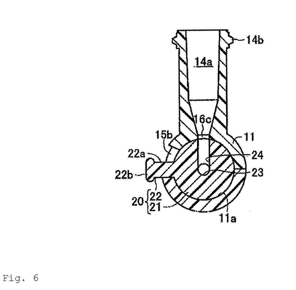
- the chamber part 11 is formed in an approximately spherical shape, inside of which, as shown in Fig. 4 or Fig. 6 , the open space part 11a the inner peripheral surface of which is formed approximately spherically.
- a horizontal guide hole 15a extending anteroposteriorly is formed at the centre in the vertical direction on the side surface (the surface shown in Fig. 2 ) of the chamber part 11 passing through inside the chamber part 11 outward, and a vertical guide hole 15b passing through inside the chamber part 11 outward is extending from the centre of the cross direction of the horizontal guide hole 15a upward.
- communication hole 16a,16b and 16c are formed at portions opposing to the upstream branch-tube 12, the downstream branch-tube 13 and the merge-branch-tube 14 respectively in the chamber part 11.
- the upstream branch-tube 12 is provided at a portion corresponding to a communication hole 16a in the outer peripheral surface of the chamber part 11, and through the use of the communication hole 16a, the open space part 11a in the chamber part 11 is communicated with a flow passage 12a formed inside the upstream branch-tube 12.
- downstream branch-tube 13 is provided at a portion corresponding to a communication holes 16b in the outer peripheral surface of the chamber part 11, and through the use of the communication holes 16b, the open space part 11a inside the chamber part 11 is communicated with a flow passage 13a formed inside the downstream branch-tube 13.
- the merge-branch-tube 14 is provided at a portion corresponding to a communication hole 16c in the outer peripheral surface of the chamber part 11, through the use of the communication hole 16c, the open space part 11a inside the chamber part 11 is communicated with a flow passage 14a formed inside the merge-branch-tube 14.
- the upstream branch-tube 12 is integrally formed with the chamber part 11, the flow passage 12a formed inside thereof formed in a tapered shape with the diameter of the rear end opening side being larger and the diameter of the chamber part 11 side being smaller.
- this flow passage 12a is formed in a somewhat steep tapered shape with the diameter of the communication hole 16a side portion being larger toward the communication hole 16a and being smaller away form the communication hole 16a.
- the upstream portion (the right side portion in Fig. 4 and Fig. 5 ) of the flow passage 12a is formed in a gradual tapered shape with the diameter gradually is larger toward the opening of the upstream branch-tube 12.
- a connecting screw part 12b is formed at the outer peripheral surface of the opening of the upstream branch-tube 12.
- the downstream branch-tube 13 is integrally formed with the chamber part 11 and is comprised of a base part 13b located at the chamber part 11 side and a male luer part 13c which is positioned at the tip side and formed thinner than a base part 13b. Moreover, the male luer part 13c is formed in a tapered-off shape with the tip side being thinner than the base part 13b side, gradually tapered-off to the point. And, a protrusion part 13d is formed along the circumference at the boundary part between the base part 13b and the male luer part 13c in the outer peripheral surface of the downstream branch-tube 13.
- the merge-branch-tube 14 formed at the upside of the chamber part 11 is formed in a cylindrical shape with the size and the axial length being approximately the same degree as the upstream branch-tube 12.
- the flow passage 14a formed inside this merge-branch-tube 14 is formed in a somewhat steep tapered shape with the diameter in the communication hole 16c side portion being smaller toward the communication hole 16c and larger away from the communication hole 16c.
- the upstream portion (the top side portion in Fig. 5 ) of the flow passage 14a is formed in a gradually tapered shape with the diameter being gradually larger toward the openings of the merge-branch-tube 14.
- a connecting screw part 14b is formed at the outer peripheral surface of the opening of the merge-branch-tube 14.
- the valve body 20 is comprised of the valve main body 21 formed in an approximately spherical shape installed at the open space part 11a of the chamber part 11, and the rod-shaped operating part 22 passing through the guide hole 15 comprised of the horizontal guide hole 15a and the vertical guide hole 15b extending from the valve main body 21 to the outside.
- the valve main body 21 is installed in the chamber part 11 with the outer surface being slidingly contacted with the inner surface of the chamber part 11, and is rotatable around the centre of spherical shape in every direction to the chamber part 11, the rotation range of which however is restricted by the engagement between a rod-shaped operating part 22 and the guide hole 15.
- the horizontal flow passages 23 passing through the valve main body 21 and extending anteroposteriorly, and the vertical flow passages 24 passing through from the centre of the cross direction of the horizontal flow passages 23 to the upper part of the valve main body 21 are formed inside the valve main body 21.
- the horizontal flow passages 23 is constituted by forming circular arc shaped expanded (wide-angle) open space parts 23b,23c extending to one of side part sides (the upper part side in Fig. 4 ) respectively, at both the front and rear ends of thin cylindrically shaped open space part 23a extending anteroposteriorly.
- the expanded (wide-angle) open space parts 23b,23c are, with the respective widths in the height direction being the same with the width of the open space part 23a, extending face-to-face so as to be along the inner surface of the chamber part 11.
- the width in the horizontal direction of the expanded (wide-angle) open space part 23b is determined to approximately 2 times of the diameter of the communication hole 16a
- the width in the horizontal direction of expanded (wide-angle) open space part 23c is determined to approximately 2 times of the diameter of the communication holes 16b.
- a vertical flow passage 24 is comprised of a thin cylindrically shaped open space part extending in the vertical (up/down) direction, the diameter of which is determined to be the same as the diameter of the open space part 23a and the diameter of the communication hole 16c. Moreover, the upper end opening of a vertical flow passage 24 is formed at a position to be communicated with the communication hole 16c when the rod-shaped operating part 22 is positioned at the centre of the horizontal guide hole 15a.
- the valve main body 21 simply rotates in the axis direction around the centre axis of the open space part 23a, and therefore the communication status of the upstream branch-tube 12 and the downstream branch-tube 13 through the use of the horizontal flow passages 23 does not change.
- the vertical flow passage 24 is portioned at the upside of the portion shown in the figures.
- the rod-shaped operating part 22 is comprised of a cylindrically shaped connection part 22a extending from the outer surface of the valve main body 21 to the outside, and an approximately disc-shaped grip part 22b formed at the tip part of the connection part 22a.
- the communication status of the upstream branch-tube 12, the downstream branch-tube 13 and the merge-branch-tube 14 can be switched between communication and shut-off statuses.
- the male luer parts (not shown) provided at the tip parts of infusion tubes extending from containers and the likes containing drug solutions to be supplied to the patient are connected to the upstream branch-tube 12 and the merge-branch-tube 14 respectively.
- the downstream branch-tube 13 is connected to the rear end parts of infusion tubes (not shown) to which indwelling needles for puncturing and being indwelled within the patient are connected.
- the rod-shaped operating part 22 is manipulated, for example, is moved to the upper end side of the vertical guide hole 15b to pump the drug solutions in the containers and the likes connected to the upstream branch-tube 12 side into the patient, thereby drug solutions can be supplied into the patient from the upstream branch-tube 12 through the downstream branch-tube 13.
- the other drug solutions and the likes are supplied into the vertical flow passage 24 through the use of the merge-branch-tube 14.
- the rod-shaped operating part 22 being moved to the lower end part (the centre of the horizontal guide hole 15a) of the vertical guide hole 15b, and the drug solutions in the container and the likes connected to the merge-branch-tube 14 are pumped into the merge-branch-tube 14 side.
- the drug solutions supplied from the upstream branch-tube 12 side and the drug solutions supplied from the merge-branch-tube 14 side are mixed in the horizontal flow passages 23 and supplied into the patient's body.
- the rod-shaped operating part 22 is moved to the rear end side of the horizontal guide hole 15a to achieve the condition in Fig. 8 , thereby, the supply of the drug solutions from the upstream branch-tube 12 side can be stopped to supply only the drug solutions from the merge-branch-tube 14 side into the patient's body.
- the rod-shaped operating part 22 is moved to the front end side of the horizontal guide hole 15a, making the condition the same in Fig.
- the supply of the drug solutions into the downstream branch-tube 13 side can be stopped and at the same time, the drug solutions from the merge-branch-tube 14 side can be channeled off to the upstream branch-tube 12 side, and the drug solutions of the upstream branch-tube 12 side and the drug solutions from the merge-branch-tube 14 can be mixed at the upstream branch-tube 12 side. And, the mixed drug solutions can be again supplied into the patient's body by allowing the downstream branch-tube 13 to communicate with the horizontal flow passages 23.
- the open space part, the inner surface of which is formed approximately spherically 11a is provided inside the chamber part 11, and the valve main body in an approximately spherical shape 21 is installed in this open space part 11a.
- the valve main body 21 is rotatablly installed with the outer surface being slidingly contacted with the inner surface of the chamber part 11, and in the inside thereof, the horizontal flow passages 23 capable of allowing the upstream branch-tube 12 to communicate with the downstream branch-tube 13 or shutting-off the communication, and the vertical flow passages 24 capable of allowing the communication between the merge-branch-tube 14 and the horizontal flow passages 23 to open or shut-off.
- the guide hole 15 consisting of the horizontal guide hole 15a and the vertical guide hole 15b is formed, and the rod-shaped operating part 22 extending from the valve main body 21 passing through the guide hole 15 to the outside can be moved along the guide hole 15, thereby the communication between the upstream branch-tube 12 and the downstream branch-tube 13 can be opened or shut-off, as well as the communication between the merge-branch-tube 14 and the horizontal flow passages 23 can be opened or shut-off. Consequently, the switching operation between the upstream branch-tube 12, the downstream branch-tube 13 or the merge-branch-tube 14 can be performed by simply moving the rod-shaped operating part 22 along the guide hole 15, allowing one hand operation.
- Fig. 11 shows a medical stopcock-B according to the second embodiment of the present invention.
- the diameter of a communication holes 36c formed at the upper part of the chamber part 31 is made larger, and the peripheral surface is formed in a tapered shape with the chamber part 31 side being made larger but smaller toward the upper part side.
- a merge-branch-tube 34 formed at the upside of the chamber part 31 is formed in a cylindrical shape with the diameter larger and the axial length shorter than the aforementioned merge-branch-tube 14.
- the peripheral surface of flow passage 34a formed inside this merge-branch-tube 34 is formed with tapered surface continuous to the tapered surface of the communication holes 36c, with the diameter being larger toward the communication holes 36c and smaller away from the communication holes 36c.
- the upside portion of the flow passage 34a is comprised of the opening with the diameter being the same from the upper end of the flow passage 34a to the outside.
- the connecting screw part 34b is formed at the outer peripheral surface of the upper end opening of the merge-branch-tube 34.
- a rubber plug 37 consisting of naturally occurring rubber or synthetic rubber is attached at the upper end of inside the merge-branch-tube 34.
- This rubber plug 37 is provided with a slit 37a vertically passing through between the inner side of the chamber part 31 and the outer side of the merge-branch-tube 34, and this slit 37a is obstructed by the elasticity of the rubber plug 37 when the merge-branch-tube 34 is not in use.
- the male luer part of the syringe and the likes can be inserted into the slit 37a of the rubber plug 37 to allow the syringe to communicate with a flow passage 34a.
- the guide hole formed at the chamber part 31 is comprised of the horizontal guide hole only but not the vertical guide hole. Consequently, by the rotation of the valve main body 35, the communication between an upstream branch-tube 32 and a downstream branch-tube 33 can be opened or shut-off, and a vertical flow passage 38 formed at the valve main body 35 is constantly in communication with the flow passage 34a.
- the constitutions of this medical stopcock-B other than the portions described above are the same as the aforementioned medical stopcock-A. Thus, the identical notations are assigned to the identical parts and the detailed descriptions are omitted.
- the rod-shaped operating part 22 can be moved to the centre of the horizontal guide hole, thereby the syringe can be made to communicate with the upstream branch-tube 32 and the downstream branch-tube 33.
- 2 kinds of drug solutions and the likes can be supplied into the patient's body.
- the syringe can be removed to obstruct the rubber plug 37, thereby only the upstream branch-tube 32 and the downstream branch-tube 33 are allowed to be communicated.
- the communication between the upstream branch-tube 32 and the horizontal flow passages 23 can be shut-off, thereby only the syringe and the downstream branch-tube 33 are allowed to be communicated.
- the medical stopcock according to the present invention is not limited to the aforementioned embodiments and may be arbitrarily modified and implemented accordingly within the scope of the invention.
- the horizontal flow passages 23 and the vertical flow passage 24 are provided insides the valve main bodies 21,35, however, this horizontal flow passages and the vertical flow passage may also be formed along the surface of the valve main body.
- plural branch-tubes are comprised of 3 branch-tubes: the upstream branch-tube 12 (32), the downstream branch-tube 13 (33) and the merge-branch-tube 14 (34), however, these tubes may also be comprised of 2 branch-tubes.
- the rubber plug 37 is provided with the slit 37a, and the male luer part is inserted into the slit 37a to allow the syringe to communicate with the merge-branch-tube 34, however, in lieu of the syringe, an insertion part of a connector, or needles such as an injection needle or a dull needle may also be inserted into the rubber plug 37.
- an injection needle is inserted, the slit 37a provided for the rubber plug 37 is no longer required.
- the constitutions of any other portions forming the medical stopcock other than described above may also be arbitrarily modified and implemented accordingly.
- 10 ...Medical stopcock main body, 11,31...Chamber parts, 11a...Open space part, 12,32...Upstream branch-tubes, 12a,13a,14a,and 34a...Flow passages, 13,33...Downstream branch-tubes, 14,34...Merge-branch-tubes, 15...Guide hole, 15a...Horizontal guide hole, 15b...Vertical guide hole, 20...Valve disc, 21,35...Valve main bodies, 22...Rod-shaped operating part, 23...Horizontal flow passages, 24,38...Vertical flow passages, A,B...Medical stopcock.
Landscapes
- Health & Medical Sciences (AREA)
- Heart & Thoracic Surgery (AREA)
- Pulmonology (AREA)
- Engineering & Computer Science (AREA)
- Anesthesiology (AREA)
- Biomedical Technology (AREA)
- Hematology (AREA)
- Life Sciences & Earth Sciences (AREA)
- Animal Behavior & Ethology (AREA)
- General Health & Medical Sciences (AREA)
- Public Health (AREA)
- Veterinary Medicine (AREA)
- Infusion, Injection, And Reservoir Apparatuses (AREA)
Abstract

Description
- The present invention relates to a medical stopcock comprising plural branch-tubes connected to the plural infusion tubes and the likes used for medical purposes and capable of switching the communication and shut-off statuses of each branch-tube.
- Traditionally, plural infusion tubes are used to supply fluids such as drug solutions into a patient's body, in cases like this, medical stopcocks are used to allow the solutions to communicate between each infusion tub or shut-off the communication. Among the foregoing medical stopcocks, there exist medical stopcocks capable of allowing to open or shut-off the communication between each branch-tube and the chamber part by moving the operating part in the axis direction of the chamber part, wherein the chamber part is formed in a cylindrical shape (for example, see Patent Literature 1). This medical stopcock is formed in such a manner that 2 branch-tubes are provided interposing the peripheral surface of an approximately cylindrically shaped chamber part, and the valve body in the axis direction in the chamber part can be rotated to open and close the communication between the 2 branch-tubes.
- However, this medical stopcock is provided with only 2 branch-tubes, and only capable of simply allowing to open or shut-off the communication between the 2 branch-tubes. Hence, this medical stopcock cannot be connected to plural lines of infusion tubes and the likes used for medical purposes to switch the communication and shut-off statuses of each infusion tube. Moreover, in order to allow the 2 branch-tubes to communicate with one another or shut-off the communication one another, the rotational manipulation of the valve body must be performed, posing a difficulty to operate. Consequently, the medical stopcock comprising 3 branch-tubes, capable of switching the flow passage by performing the rotational manipulation of the cock in the axis direction of the valve body has also been developed, however even in such a medical stopcock, during the manipulation, the main body of the medical stopcock needs to be held by one hand, and the cock needs to be manipulated by the other hand, and therefore posing a problem that it is difficult to operate.
- The present invention is made in consideration of the foregoing situations, and the purpose is to provide a medical stopcock allowing an easy switching operation of the flow passages of plural branch-tubes.
- To achieve the aforementioned purpose, a medical stopcock according to the present invention is constitutionally characterised by comprising: a chamber part comprising an open space part, the inner surface of which is formed approximately spherically, and the guide hole located at a predetermined portion of the inner surface through to the outside; a medical stopcock main body consisting of plural branch-tubes each of which having a flow passage spaced from the outer peripheral surface of the chamber part and extending outward respectively to communicate with inside said chamber part; a valve main body consisting of an approximately spherical body installed inside the chamber part and provided with flow passages formed at a predetermined portion thereon and capable of allowing predetermined branch-tubes out of said plural branch-tubes to communicate with one another through the use of the flow passages or of shutting-off the communication by rotationally moving along the inner surface of the chamber part; and a rod-shaped operating part allowing the flow passages of the valve main body to communicate with predetermined branch-tubes out of the plural branch-tubes, or shutting-off the communication by passing through the guide hole from the outer peripheral surface of the valve main body and extending outward and by moving along the guide hole.
- In the medical stopcock of the present invention constituted as described above, the open space part, the inner surface of which is formed approximately spherically is provided inside the medical stopcock main body provided with the plural branch-tubes, and the valve main body in an approximately spherical shape comprising the flow passages capable of allowing the predetermined branch-tubes out of the plural branch-tubes to communicate with one another or shut-off the communication one another is installed in this open space part. Furthermore, the medical stopcock is formed in such a manner that the valve main body is rotated in the chamber part by moving the rod-shaped operating part, which is passing through the guide hole formed at the valve main body to the chamber part extending to outside, along the guide hole allowing the predetermined branch-tubes out of the plural branch-tubes to communicate with one another or shut-off the communication through the use of the flow passages of the valve main body.
- Consequently, the switching operation between each branch-tube can be performed simply by moving the rod-shaped operating part along the guide hole, and whereas the movement of the rod-shaped operating part is a rotation around the valve main body as a pivot point, one hand operation can be performed. More specifically, the rod-shaped operating part may be operated with the thumb of a hand holding the chamber part. Moreover, the predetermined portion of the valve main body on which the flow passages are formed may be either the inside or the surface of the valve main body, and the flow passages may be comprised of holes passing through the valve main body or grooves formed along the surface of the valve main body In addition, the "approximately spherical surface" of the inner surface of the chamber part and the "approximately spherical body" of the valve main body means that they are, in their entirety, a spherical surface and a spherical body respectively, however are not a perfect spherical surface and a perfect spherical body due to the hole and the flow passages provided thereon, and the valve main body is slidingly contacting with the inner surface of the chamber part and is rotatable.
- Moreover, another constitutional characteristic of the medical stopcock according to the present invention is that the plural branch-tubes is comprised of a pair of horizontal branch-tubes extending from both sides of the outer peripheral surface of the chamber part outward and the vertical branch-tube extending from the top side of the outer peripheral surface of the chamber part upward, and that the flow passages of the valve main body is comprised of the horizontal flow passages capable of allowing the pair of horizontal branch-tubes to communicate with one another or shut-off the communication and the vertical flow passage capable of allowing the horizontal flow passages and the vertical branch-tube to communicate with one another or shut-off the communication.
- This allows the horizontal flow passages to communicate with the pair of horizontal branch-tubes by positioning the valve main body at a predetermined location in the horizontal direction in the chamber part and, while maintaining the condition, also allows all of the pair of horizontal branch-tubes and the vertical branch-tube to communicate with one another through the use of the flow passages of the valve main body by positioning the valve main body at a predetermined location in the vertical direction to allow the vertical passage to communicate with the vertical branch-tube. Thereby, 2 kinds of drug solutions and the likes can be supplied into a patient's body from the horizontal branch-tube and the vertical branch-tube. Moreover, in the condition thereof, one side of the pair of horizontal branch-tubes can be shut-off by rotationally moving the valve main body to one side in the horizontal direction, and the other side of the pair of horizontal branch-tubes can be shut-off by rotationally moving the valve main body to the other side in the horizontal direction. In addition, with the condition in which all of the pair of horizontal branch-tubes and the vertical branch-tube are made to communicate, the vertical branch-tube can be shut-off by rotationally moving the valve main body in the vertical direction.
- Moreover, another constitutional characteristic of the medical stopcock according to the present invention is that the guide hole is comprised of the horizontal guide hole extending in the horizontal direction and the vertical guide hole extending from the approximately centre of the horizontal guide hole upward or downward, and the rod-shaped operating part can be moved along the horizontal guide hole to allow the pair of horizontal branch-tubes to communicate with one another or shut-off the communication, and that the rod-shaped operating part can be moved along the vertical guide hole to allow the horizontal flow passages and the vertical branch-tube to communicate with one another or shut-off the communication.
- In this case, it can be constituted in such a manner that when the rod-shaped operating part is positioned at a portion where the horizontal guide hole and the vertical guide hole are intersected with one another, all of the pair of horizontal branch-tubes can be communicated with the vertical branch-tube, and when the rod-shaped operating part is moved from the position thereof, the branch-tubes located in the direction of the movement thereof can be shut-off or communicated. This allows the communication and shut-off statuses of each of the branch-tubes to be identified according to the position of the rod-shaped operating part, thereby an operational error can be prevented.
- Moreover, another constitutional characteristic of the medical stopcock according to the present invention is that the plural branch-tubes are comprised of the pair of horizontal branch-tubes extending from both sides of the outer peripheral surface of the chamber part outward and the vertical branch-tube extending from the top side of the outer peripheral surface of the chamber part upward, and that the flow passages of the valve main body is comprised of the horizontal flow passages capable of allowing the pair of horizontal branch-tubes to communicate with one another or shut-off the communication and the vertical flow passage allowing the horizontal flow passages to constantly communicate with the vertical branch-tube. In this case, the guide hole is comprised of the horizontal guide hole extending in the horizontal direction so as to be capable of allowing the pair of horizontal branch-tubes to communicate with one another or shut-off the communication by moving the rod-shaped operating part along the horizontal guide hole.
- In this case, the vertical branch-tube may be attached to a rubber plug into which the male luer part of the syringe, the puncture needle and the likes can be inserted. This allows the pair of horizontal branch-tubes to communicate with one another or shut-off the communication by positioning the valve main body at a predetermined location in the horizontal direction in the chamber part, and as required, the other drug solutions and the likes can be supplied into the chamber part from the vertical branch-tube.
- Moreover, another constitutional characteristic of the medical stopcock according to the present invention is that both side portions of the valve main body opposing respectively to the flow passages of the pair of horizontal branch-tubes in the horizontal flow passages is formed in such a manner that when the valve main body is rotated to one side in the horizontal direction by the predetermined angle from the condition that the horizontal flow passages of the valve main body is made to communicate with the flow passages of the pair of horizontal branch-tubes respectively, the communication condition between the horizontal flow passages and the flow passages of one side branch-tube of the pair of branch-tubes is maintained, and the communication between the horizontal flow passages and the flow passage of the other branch-tube of the pair of branch-tubes is shut-off, whereas when the valve main body is rotated to the other side in the horizontal direction by the predetermined angle, the communication condition between the horizontal flow passages and the flow passage of the other branch-tube is maintained and the communication between the horizontal flow passages and the flow passage of one of branch-tubes is shut-off.
- In this case, the term "by the predetermined angle" means that for example, based on the premises that the entire openings of the flow passages of the pair of horizontal branch-tubes face opposing to the horizontal flow passages, when the horizontal flow passages and the pair of horizontal branch-tubes are made to communicate with one another, the movement length of the valve main body in the outer peripheral surface is made equal to or greater than the width of the flow passage of one of branch-tubes in order to shut-off the flow passage of one of branch-tubes, and the movement length of the valve main body in the outer peripheral surface is made equal to or greater than the width of the flow passage of the other branch-tube in order to shut-off the flow passage of the other branch-tube. Hence, where the width of the flow passage of one of branch-tubes is different form the width of the flow passage of the other branch-tube, the respective predetermined angles may also be different.
- Moreover, in the event that the horizontal flow passages is comprised of a hole passing through the valve main body, both end opening side portions of the horizontal flow passages can be formed as holes with the dimension wider in the horizontal direction than that of the centre side portion to allow the communications between the horizontal flow passages and the pair of horizontal branch-tubes to open or shut-off. In addition, in the event that the horizontal flow passages are comprised of grooves formed along the surface of the valve main body, when the horizontal flow passages are made to communicate with the pair of horizontal branch-tubes one another, each of the both end parts of the horizontal flow passages can be positioned at each of the openings of the pair of branch-tubes to allow the communications between the horizontal flow passages and the pair of horizontal branch-tubes to open or shut-off.
- Hereinafter, a medical stopcock according to the first embodiment of the present invention will be descried in detail with reference to drawings.
Fig. 1 orFig. 3 shows a medical stopcock-A according to the embodiment, this medical stopcock-A is comprised of a medical stopcockmain body 10 and thevalve body 20 installed inside the medical stopcockmain body 10. The medical stopcockmain body 10 is comprised of: the approximately sphere-shaped chamber part 11; an upstream branch-tube 12 and a downstream branch-tube 13 as the pair of horizontal branch-tubes of the present invention connected to both front and rear sides (both right and left sides inFig. 1 and Fig. 2 , hereinafter the direction located in the upstream of the drug solution flow and the likes is described as the "rear side" and the direction located in the downstream is described as the "front side") in the outer peripheral surface of thechamber part 11 so as to be extending in the horizontal direction along coaxially; and a merge-branch-tube 14 as the vertical branch-tube of the present invention formed at the upper part in the outer peripheral surface of thechamber part 11. - More specifically, the upstream branch-
tube 12, the downstream branch-tube 13 and the merge-branch-tube 14 are provided on the outer peripheral surface of thechamber part 11 circumferentially spaced at 90-degree, and the merge-branch-tube 14 is extending upward so as to be perpendicularly intersecting with the upstream branch-tube 12 and the downstream branch-tube 13 extending in the horizontal direction. Thechamber part 11 is formed in an approximately spherical shape, inside of which, as shown inFig. 4 orFig. 6 , theopen space part 11a the inner peripheral surface of which is formed approximately spherically. Moreover, ahorizontal guide hole 15a extending anteroposteriorly is formed at the centre in the vertical direction on the side surface (the surface shown inFig. 2 ) of thechamber part 11 passing through inside thechamber part 11 outward, and avertical guide hole 15b passing through inside thechamber part 11 outward is extending from the centre of the cross direction of thehorizontal guide hole 15a upward. - In addition,
communication hole tube 12, the downstream branch-tube 13 and the merge-branch-tube 14 respectively in thechamber part 11. And, the upstream branch-tube 12 is provided at a portion corresponding to acommunication hole 16a in the outer peripheral surface of thechamber part 11, and through the use of thecommunication hole 16a, theopen space part 11a in thechamber part 11 is communicated with aflow passage 12a formed inside the upstream branch-tube 12. Moreover, the downstream branch-tube 13 is provided at a portion corresponding to acommunication holes 16b in the outer peripheral surface of thechamber part 11, and through the use of thecommunication holes 16b, theopen space part 11a inside thechamber part 11 is communicated with aflow passage 13a formed inside the downstream branch-tube 13. - In addition, the merge-branch-
tube 14 is provided at a portion corresponding to acommunication hole 16c in the outer peripheral surface of thechamber part 11, through the use of thecommunication hole 16c, theopen space part 11a inside thechamber part 11 is communicated with aflow passage 14a formed inside the merge-branch-tube 14. Moreover, the upstream branch-tube 12 is integrally formed with thechamber part 11, theflow passage 12a formed inside thereof formed in a tapered shape with the diameter of the rear end opening side being larger and the diameter of thechamber part 11 side being smaller. - To describe this more specifically, this
flow passage 12a is formed in a somewhat steep tapered shape with the diameter of thecommunication hole 16a side portion being larger toward thecommunication hole 16a and being smaller away form thecommunication hole 16a. Moreover, the upstream portion (the right side portion inFig. 4 andFig. 5 ) of theflow passage 12a is formed in a gradual tapered shape with the diameter gradually is larger toward the opening of the upstream branch-tube 12. And, a connectingscrew part 12b is formed at the outer peripheral surface of the opening of the upstream branch-tube 12. - The downstream branch-
tube 13 is integrally formed with thechamber part 11 and is comprised of abase part 13b located at thechamber part 11 side and amale luer part 13c which is positioned at the tip side and formed thinner than abase part 13b. Moreover, themale luer part 13c is formed in a tapered-off shape with the tip side being thinner than thebase part 13b side, gradually tapered-off to the point. And, aprotrusion part 13d is formed along the circumference at the boundary part between thebase part 13b and themale luer part 13c in the outer peripheral surface of the downstream branch-tube 13. - the merge-branch-
tube 14 formed at the upside of thechamber part 11 is formed in a cylindrical shape with the size and the axial length being approximately the same degree as the upstream branch-tube 12. theflow passage 14a formed inside this merge-branch-tube 14 is formed in a somewhat steep tapered shape with the diameter in thecommunication hole 16c side portion being smaller toward thecommunication hole 16c and larger away from thecommunication hole 16c. And, the upstream portion (the top side portion inFig. 5 ) of theflow passage 14a is formed in a gradually tapered shape with the diameter being gradually larger toward the openings of the merge-branch-tube 14. And, a connectingscrew part 14b is formed at the outer peripheral surface of the opening of the merge-branch-tube 14. - The
valve body 20 is comprised of the valvemain body 21 formed in an approximately spherical shape installed at theopen space part 11a of thechamber part 11, and the rod-shaped operating part 22 passing through theguide hole 15 comprised of thehorizontal guide hole 15a and thevertical guide hole 15b extending from the valvemain body 21 to the outside. The valvemain body 21 is installed in thechamber part 11 with the outer surface being slidingly contacted with the inner surface of thechamber part 11, and is rotatable around the centre of spherical shape in every direction to thechamber part 11, the rotation range of which however is restricted by the engagement between a rod-shaped operating part 22 and theguide hole 15. - And, as shown in
Fig. 4 orFig. 6 , thehorizontal flow passages 23 passing through the valvemain body 21 and extending anteroposteriorly, and thevertical flow passages 24 passing through from the centre of the cross direction of thehorizontal flow passages 23 to the upper part of the valvemain body 21 are formed inside the valvemain body 21. Thehorizontal flow passages 23 is constituted by forming circular arc shaped expanded (wide-angle)open space parts Fig. 4 ) respectively, at both the front and rear ends of thin cylindrically shapedopen space part 23a extending anteroposteriorly. The expanded (wide-angle)open space parts open space part 23a, extending face-to-face so as to be along the inner surface of thechamber part 11. - And, the width in the horizontal direction of the expanded (wide-angle)
open space part 23b is determined to approximately 2 times of the diameter of thecommunication hole 16a, and the width in the horizontal direction of expanded (wide-angle)open space part 23c is determined to approximately 2 times of the diameter of thecommunication holes 16b. Consequently, as shown inFig. 4 , when the rod-shaped operating part 22 is positioned at the centre of thehorizontal guide hole 15a, theopen space part 23a side portion of the expanded (wide-angle)open space part 23b and thecommunication hole 16a are opposed, and the expanded (wide-angle)open space part 23c and thecommunication holes 16b are communicated. Thereby, theflow passage 12a of the upstream branch-tube 12 and theflow passage 13a of the downstream branch-tube 13 are communicated through the use of thehorizontal flow passages 23 of the valvemain body 21. - Moreover, as shown in
Fig. 7 , when the rod-shapedoperating part 22 is positioned at the front end side of thehorizontal guide hole 15a, the tip side portion of the expanded (wide-angle)open space part 23b and thecommunication hole 16a are opposed, and the expanded (wide-angle)open space part 23c is obstructed to the inner surface of thechamber part 11, and thecommunication holes 16b is obstructed to the outer surface of the valvemain body 21. Consequently, theflow passage 12a of the upstream branch-tube 12 and thehorizontal flow passages 23 of the valvemain body 21 are communicated, however, the communication status of thehorizontal flow passages 23 of the valvemain body 21 and theflow passage 13a of the downstream branch-tube 13 becomes "shut-off". In addition, as shown inFig. 8 , when the rod-shapedoperating part 22 is positioned at rear end side of thehorizontal guide hole 15a, the expanded (wide-angle)open space part 23b is obstructed to the inner surface of thechamber part 11, and thecommunication hole 16a is obstructed to the outer surface of the valvemain body 21. - Moreover, the tip side portion of the expanded (wide-angle)
open space part 23c is opposed to the communication holes 16b to communicate. Consequently, the communication status of theflow passage 12a of the upstream branch-tube 12 and thehorizontal flow passages 23 of the valvemain body 21 are shut-off, and thehorizontal flow passages 23 of the valvemain body 21 and theflow passage 13a of the downstream branch-tube 13 are communicated. Avertical flow passage 24 is comprised of a thin cylindrically shaped open space part extending in the vertical (up/down) direction, the diameter of which is determined to be the same as the diameter of theopen space part 23a and the diameter of thecommunication hole 16c. Moreover, the upper end opening of avertical flow passage 24 is formed at a position to be communicated with thecommunication hole 16c when the rod-shapedoperating part 22 is positioned at the centre of thehorizontal guide hole 15a. - Hence, in the condition shown in
Fig. 4 andFig. 9 , the upstream branch-tube 12 and the downstream branch-tube 13 are communicated through the use of thehorizontal flow passages 23, and theflow passage 14a of the merge-branch-tube 14 and thehorizontal flow passages 23 are communicated through the use of thevertical flow passage 24. Consequently, all of the upstream branch-tube 12, the downstream branch-tube 13 and the merge-branch-tube 14 are communicated through the use of thehorizontal flow passages 23 of the valvemain body 21 and thevertical flow passage 24. And, as shown inFig. 10 , when the rod-shapedoperating part 22 is made to move to the upper end side of thevertical guide hole 15b, the upper end opening of thevertical flow passage 24 is obstructed to the inner surface of thechamber part 11, and thecommunication hole 16c is obstructed to the outer surface of the valvemain body 21. Consequently, the communication status of theflow passage 14a of the merge-branch-tube 14 and thevertical flow passage 24 of the valvemain body 21 becomes "shut-off". - In this case, the valve
main body 21 simply rotates in the axis direction around the centre axis of theopen space part 23a, and therefore the communication status of the upstream branch-tube 12 and the downstream branch-tube 13 through the use of thehorizontal flow passages 23 does not change. Incidentally, inFig. 4 ,Fig. 7 and Fig. 8 , thevertical flow passage 24 is portioned at the upside of the portion shown in the figures. Moreover, the rod-shapedoperating part 22 is comprised of a cylindrically shapedconnection part 22a extending from the outer surface of the valvemain body 21 to the outside, and an approximately disc-shapedgrip part 22b formed at the tip part of theconnection part 22a. And, by manipulating thegrip part 22b with fingers to move the rod-shapedoperating part 22 along theguide hole 15, as mentioned above, the communication status of the upstream branch-tube 12, the downstream branch-tube 13 and the merge-branch-tube 14 can be switched between communication and shut-off statuses. - In this constitution, in the event that predetermined drug solutions are supplied into a patient (not shown) body, the male luer parts (not shown) provided at the tip parts of infusion tubes extending from containers and the likes containing drug solutions to be supplied to the patient, are connected to the upstream branch-
tube 12 and the merge-branch-tube 14 respectively. Moreover, the downstream branch-tube 13 is connected to the rear end parts of infusion tubes (not shown) to which indwelling needles for puncturing and being indwelled within the patient are connected. And, with the indwelling needles punctured the patient's body and indwelled within, the rod-shapedoperating part 22 is manipulated, for example, is moved to the upper end side of thevertical guide hole 15b to pump the drug solutions in the containers and the likes connected to the upstream branch-tube 12 side into the patient, thereby drug solutions can be supplied into the patient from the upstream branch-tube 12 through the downstream branch-tube 13. - Moreover, in addition to drug solutions supplied from the upstream branch-
tube 12 side, in the event that the other drug solutions and the likes are supplied into the patient, the other drug solutions and the likes are supplied into thevertical flow passage 24 through the use of the merge-branch-tube 14. In this case, with the rod-shapedoperating part 22 being moved to the lower end part (the centre of thehorizontal guide hole 15a) of thevertical guide hole 15b, and the drug solutions in the container and the likes connected to the merge-branch-tube 14 are pumped into the merge-branch-tube 14 side. Thereby, the drug solutions supplied from the upstream branch-tube 12 side and the drug solutions supplied from the merge-branch-tube 14 side are mixed in thehorizontal flow passages 23 and supplied into the patient's body. - Moreover, from the condition thereof, the rod-shaped
operating part 22 is moved to the rear end side of thehorizontal guide hole 15a to achieve the condition inFig. 8 , thereby, the supply of the drug solutions from the upstream branch-tube 12 side can be stopped to supply only the drug solutions from the merge-branch-tube 14 side into the patient's body. In addition, the rod-shapedoperating part 22 is moved to the front end side of thehorizontal guide hole 15a, making the condition the same inFig. 7 , thereby, the supply of the drug solutions into the downstream branch-tube 13 side can be stopped and at the same time, the drug solutions from the merge-branch-tube 14 side can be channeled off to the upstream branch-tube 12 side, and the drug solutions of the upstream branch-tube 12 side and the drug solutions from the merge-branch-tube 14 can be mixed at the upstream branch-tube 12 side. And, the mixed drug solutions can be again supplied into the patient's body by allowing the downstream branch-tube 13 to communicate with thehorizontal flow passages 23. - Thus, in a medical stopcock-A according to the embodiment, the open space part, the inner surface of which is formed approximately spherically 11a is provided inside the
chamber part 11, and the valve main body in an approximatelyspherical shape 21 is installed in thisopen space part 11a. Moreover, the valvemain body 21 is rotatablly installed with the outer surface being slidingly contacted with the inner surface of thechamber part 11, and in the inside thereof, thehorizontal flow passages 23 capable of allowing the upstream branch-tube 12 to communicate with the downstream branch-tube 13 or shutting-off the communication, and thevertical flow passages 24 capable of allowing the communication between the merge-branch-tube 14 and thehorizontal flow passages 23 to open or shut-off. - Moreover, in the
chamber part 11, theguide hole 15 consisting of thehorizontal guide hole 15a and thevertical guide hole 15b is formed, and the rod-shapedoperating part 22 extending from the valvemain body 21 passing through theguide hole 15 to the outside can be moved along theguide hole 15, thereby the communication between the upstream branch-tube 12 and the downstream branch-tube 13 can be opened or shut-off, as well as the communication between the merge-branch-tube 14 and thehorizontal flow passages 23 can be opened or shut-off. Consequently, the switching operation between the upstream branch-tube 12, the downstream branch-tube 13 or the merge-branch-tube 14 can be performed by simply moving the rod-shapedoperating part 22 along theguide hole 15, allowing one hand operation. - Moreover, when the rod-shaped
operating part 22 positioned at a portion? where thehorizontal guide hole 15a and thevertical guide hole 15b are intersected with one another, all of the upstream branch-tube 12, the downstream branch-tube 13 and the merge-branch-tube 14 can be communicated, and when the rod-shapedoperating part 22 is moved backward/forward or upward from the position, either one of branch-tubes is shut-off. In this case, it is formed in such a manner that the rod-shapedoperating part 22 faces in the direction of the branch-tube to be shut-off, therefore, the communication statuses of the upstream branch-tube 12, the downstream branch-tube 13 and the merge-branch-tube 14 can be identified according to the facing direction of the rod-shapedoperating part 22, Consequently, an operational error can be prevented. - Moreover,
Fig. 11 shows a medical stopcock-B according to the second embodiment of the present invention. In this medical stopcock-B, the diameter of acommunication holes 36c formed at the upper part of thechamber part 31 is made larger, and the peripheral surface is formed in a tapered shape with thechamber part 31 side being made larger but smaller toward the upper part side. And, a merge-branch-tube 34 formed at the upside of thechamber part 31 is formed in a cylindrical shape with the diameter larger and the axial length shorter than the aforementioned merge-branch-tube 14. Moreover, the peripheral surface offlow passage 34a formed inside this merge-branch-tube 34 is formed with tapered surface continuous to the tapered surface of thecommunication holes 36c, with the diameter being larger toward the communication holes 36c and smaller away from thecommunication holes 36c. - And, the upside portion of the
flow passage 34a is comprised of the opening with the diameter being the same from the upper end of theflow passage 34a to the outside. Moreover, the connectingscrew part 34b is formed at the outer peripheral surface of the upper end opening of the merge-branch-tube 34. And, arubber plug 37 consisting of naturally occurring rubber or synthetic rubber is attached at the upper end of inside the merge-branch-tube 34. Thisrubber plug 37 is provided with aslit 37a vertically passing through between the inner side of thechamber part 31 and the outer side of the merge-branch-tube 34, and thisslit 37a is obstructed by the elasticity of therubber plug 37 when the merge-branch-tube 34 is not in use. - And, when the merge-branch-
tube 34 is used, for example, the male luer part of the syringe and the likes (not shown) can be inserted into theslit 37a of therubber plug 37 to allow the syringe to communicate with aflow passage 34a. Moreover, although not illustrated, the guide hole formed at thechamber part 31 is comprised of the horizontal guide hole only but not the vertical guide hole. Consequently, by the rotation of the valvemain body 35, the communication between an upstream branch-tube 32 and a downstream branch-tube 33 can be opened or shut-off, and avertical flow passage 38 formed at the valvemain body 35 is constantly in communication with theflow passage 34a. The constitutions of this medical stopcock-B other than the portions described above are the same as the aforementioned medical stopcock-A. Thus, the identical notations are assigned to the identical parts and the detailed descriptions are omitted. - Because of the constitutions as described above, with the male luer part of the syringe being inserted into the
slit 37a of therubber plug 37, the rod-shapedoperating part 22 can be moved to the centre of the horizontal guide hole, thereby the syringe can be made to communicate with the upstream branch-tube 32 and the downstream branch-tube 33. Thereby, 2 kinds of drug solutions and the likes can be supplied into the patient's body. Moreover, while maintaining the condition thereof, the syringe can be removed to obstruct therubber plug 37, thereby only the upstream branch-tube 32 and the downstream branch-tube 33 are allowed to be communicated. In addition, with the male luer part of the syringe being inserted into theslit 37a of therubber plug 37, the communication between the upstream branch-tube 32 and thehorizontal flow passages 23 can be shut-off, thereby only the syringe and the downstream branch-tube 33 are allowed to be communicated. - Thus, only 1 kind of drug solution and the like can be supplied into the patient's body. Moreover, with the male luer part of the syringe being inserted into the
slit 37a of therubber plug 37, the communication between thehorizontal flow passages 23 and the downstream branch-tube 33 can be shut-off, thereby only the syringe and the upstream branch-tube 32 are allowed to be communicated. In addition, while maintaining the condition thereof, the syringe can be removed, thereby all the flow passages of the upstream branch-tube 32, the downstream branch-tube 33 and the merge-branch-tube 34 can be obstructed. The effects of this medical stopcock-B other than the portions described above are the same as the aforementioned medical stopcock-A. - Moreover, the medical stopcock according to the present invention is not limited to the aforementioned embodiments and may be arbitrarily modified and implemented accordingly within the scope of the invention. For example, in each of the aforementioned embodiments, the
horizontal flow passages 23 and thevertical flow passage 24 are provided insides the valvemain bodies - In addition, in the aforementioned second embodiment, the
rubber plug 37 is provided with theslit 37a, and the male luer part is inserted into theslit 37a to allow the syringe to communicate with the merge-branch-tube 34, however, in lieu of the syringe, an insertion part of a connector, or needles such as an injection needle or a dull needle may also be inserted into therubber plug 37. Incidentally, in the event that an injection needle is inserted, theslit 37a provided for therubber plug 37 is no longer required. In addition, the constitutions of any other portions forming the medical stopcock other than described above may also be arbitrarily modified and implemented accordingly. -
- [
Fig. 1 ] A plane view showing a medical stopcock according to the first embodiment of the present invention. - [
Fig. 2 ] A side view showing a medical stopcock. - [
Fig. 3 ] A back view showing a medical stopcock. - [
Fig. 4 ] A transverse cross-section view ofFig. 1 . - [
Fig. 5 ] A longitudinal cross-section view ofFig. 2 . - [
Fig. 6 ] A longitudinal cross-section viewFig. 3 . - [
Fig. 7 ] A transverse cross-section view showing the condition in which an upstream branch-tube and a merge-branch-tube are made to communicate. - [
Fig. 8 ] A transverse cross-section view showing the condition in which a downstream branch-tube and a merge-branch-tube are made to communicate. - [
Fig. 9 ] A longitudinal cross-section view showing the condition in which horizontal flow passages and a merge-branch-tube are made to communicate. - [
Fig. 10 ] A longitudinal cross-section view showing the condition in which the communication between a horizontal flow passage and a merge-branch-tube is shut-off. - [
Fig. 11 ] A longitudinal cross-section view showing the condition in which an upstream branch-tube and a downstream branch-tube of a medical stopcock according to the second embodiment of the present invention are made to communicate. - 10...Medical stopcock main body, 11,31...Chamber parts, 11a...Open space part, 12,32...Upstream branch-tubes, 12a,13a,14a,and 34a...Flow passages, 13,33...Downstream branch-tubes, 14,34...Merge-branch-tubes, 15...Guide hole, 15a...Horizontal guide hole, 15b...Vertical guide hole, 20...Valve disc, 21,35...Valve main bodies, 22...Rod-shaped operating part, 23...Horizontal flow passages, 24,38...Vertical flow passages, A,B...Medical stopcock.
Claims (6)
- A medical stopcock, characterised by comprising a medical stopcock main body consisting of: a chamber part having an open space part the inner surface of which is formed approximately spherically and a guide hole located at a predetermined portion of said inner surface through to the outside; and plural branch-tubes each of which having a flow passage spaced from the outer peripheral surface of said chamber part and extending outward respectively to communicate with inside said chamber part, and
a valve body consisting of: a valve main body consisting of an approximately spherical body installed in the said chamber part and provided with flow passages formed at a predetermined portion thereon and capable of allowing predetermined branch-tubes out of said plural branch-tubes to communicate with one another through the use of said flow passages or of shutting-off the communication by rotationally moving along the inner surface of said chamber part; and a rod-shaped operating part allowing the flow passages of said valve main body to communicate with predetermined branch-tubes out of said plural branch-tubes, or shutting-off the communication by passing through said guide hole from the outer peripheral surface of said valve main body and extending outward and by moving along said guide hole. - A medical stopcock according to claim 1, wherein said plural branch-tubes are comprised of: a pair of horizontal branch-tubes extending from both sides of the outer peripheral surface of said chamber part outward; and a vertical branch-tube extending from the top side of the outer peripheral surface of said chamber part upward, and wherein the flow passages of said valve main body are comprised of: horizontal flow passages capable of allowing said pair of horizontal branch-tubes to communicate with one another or shut-off the communication; and a vertical flow passage capable of allowing said horizontal flow passages to communicate with said vertical branch-tube or shutting-off the communication.
- A medical stopcock according to claim 2, capable of allowing said pair of horizontal branch-tubes to communicate with one another or shut-off the communication by moving said rod-shaped operating part along said horizontal guide hole, and further capable of allowing said horizontal flow passages to communicate with said vertical branch-tube by moving said rod-shaped operating part along said the vertical guide hole, or shutting-off the communication, wherein said guide hole is comprised of a horizontal guide hole extending in the horizontal direction and a vertical guide hole extending upward or downward from the approximately centre of said horizontal guide hole.
- A medical stopcock according to claim 1, characterised in that said plural branch-tubes is comprised of a pair of horizontal branch-tubes extending from both sides of the outer peripheral surface of said chamber part outward and a vertical branch-tube extending from the top side of the outer peripheral surface of said chamber part upward, and that the flow passages of said valve main body is comprised of horizontal flow passages capable of allowing said pair of horizontal branch-tubes to communicate with one another or shut-off the communication and a vertical flow passage allowing said horizontal flow passages to constantly communicate with said vertical branch-tube.
- A medical stopcock according to claim 4, capable of allowing said pair of horizontal branch-tubes to communicate with one another or shut-off the communication by moving said rod-shaped operating part along said horizontal guide hole, wherein said guide hole is comprised of a horizontal guide hole extending in the horizontal direction.
- A medical stopcock according to either one of claim 2 or 5, wherein both side portions opposing respectively to the flow passages of said pair of horizontal branch-tubes in the horizontal flow passages of said valve main body is formed in such as manner that, with the condition in which the horizontal flow passages of said valve main body are made to communicate with the flow passages of said pair of horizontal branch-tubes respectively, when said valve main body is rotated to one side in the horizontal direction by the predetermined angle, the communication condition between said horizontal flow passages and the flow passages of said pair of branch-tubes of one side branch-tube is maintained, but said horizontal flow passages and the flow passages of said pair of branch-tubes of the other branch-tube are shut-off, whereas when said valve main body is rotated to the other side in the horizontal direction by the predetermined angle,
the communication condition between said horizontal flow passages and the flow passages of said other branch-tube is maintained, but said horizontal flow passages and the flow passages of said one of branch-tubes are shut-off.
Applications Claiming Priority (1)
| Application Number | Priority Date | Filing Date | Title |
|---|---|---|---|
| JP2007028774A JP4871158B2 (en) | 2007-02-08 | 2007-02-08 | Medical stopcock |
Publications (2)
| Publication Number | Publication Date |
|---|---|
| EP1955728A1 true EP1955728A1 (en) | 2008-08-13 |
| EP1955728B1 EP1955728B1 (en) | 2010-12-15 |
Family
ID=39367668
Family Applications (1)
| Application Number | Title | Priority Date | Filing Date |
|---|---|---|---|
| EP20080101417 Not-in-force EP1955728B1 (en) | 2007-02-08 | 2008-02-08 | Stopcock valve |
Country Status (8)
| Country | Link |
|---|---|
| US (1) | US8317758B2 (en) |
| EP (1) | EP1955728B1 (en) |
| JP (1) | JP4871158B2 (en) |
| CN (1) | CN101244309B (en) |
| AT (1) | ATE491496T1 (en) |
| AU (1) | AU2008200484B2 (en) |
| CA (1) | CA2619205C (en) |
| DE (1) | DE602008003938D1 (en) |
Cited By (5)
| Publication number | Priority date | Publication date | Assignee | Title |
|---|---|---|---|---|
| CN101713470A (en) * | 2008-09-30 | 2010-05-26 | 泰科保健集团有限合伙公司 | Ball valve actuation mechanism |
| US8986263B2 (en) | 2011-03-08 | 2015-03-24 | Covidien Lp | Catheter with valve |
| US9044576B2 (en) | 2008-05-14 | 2015-06-02 | Covidien Lp | Catheter with valve |
| US9642962B2 (en) | 2008-09-26 | 2017-05-09 | Covidien Lp | Valved hemodialysis catheter |
| US10143822B2 (en) | 2012-07-05 | 2018-12-04 | Covidien Lp | Valved tip catheters |
Families Citing this family (15)
| Publication number | Priority date | Publication date | Assignee | Title |
|---|---|---|---|---|
| US8602058B1 (en) | 2009-08-12 | 2013-12-10 | Gil Del Castillo | Pushbutton stopcock assembly |
| JP5782259B2 (en) * | 2011-01-05 | 2015-09-24 | 株式会社トップ | Three-way stopcock |
| AU2012234566B2 (en) * | 2011-03-25 | 2016-06-30 | Terumo Kabushiki Kaisha | Medical stopcock |
| US9649436B2 (en) | 2011-09-21 | 2017-05-16 | Bayer Healthcare Llc | Assembly method for a fluid pump device for a continuous multi-fluid delivery system |
| US10137293B2 (en) | 2014-01-25 | 2018-11-27 | Board Of Supervisors Of Louisiana State University And Agricultural And Mechanical College | Medical stopcock valve |
| ES3030489T3 (en) | 2015-01-09 | 2025-06-30 | Bayer Healthcare Llc | Multiple fluid delivery system with multi-use disposable set and features thereof |
| KR102630666B1 (en) * | 2017-06-22 | 2024-01-29 | 엘캠 메디컬 애그리컬처럴 코오퍼레이티브 어소시에이션 리미티드 | Closed stopcock |
| CN109718116A (en) * | 2019-01-28 | 2019-05-07 | 江苏康进医疗器材有限公司 | Disposable double pocket type intestines provisions devices |
| CN111450353B (en) * | 2020-05-06 | 2020-12-08 | 梁淑芹 | Multifunctional medical infusion valve |
| CN112604038B (en) * | 2020-12-18 | 2023-04-28 | 温州市中心医院 | Cardiovascular intervention puncture drainage device |
| KR102566128B1 (en) * | 2021-01-25 | 2023-08-11 | 주식회사 엔도비전 | Medical one-touch 3-way stopcock |
| US20240042190A1 (en) * | 2021-04-30 | 2024-02-08 | Peter Salat | Valve and assembly for controlled delivery of medical fluids |
| WO2023249142A1 (en) * | 2022-06-23 | 2023-12-28 | 주식회사 엔도비전 | One-touch three-way medical stopcock |
| CN115282462B (en) * | 2022-08-04 | 2023-10-20 | 咸阳市第一人民医院 | Multifunctional three-channel medical extension tube |
| CN115645272A (en) * | 2022-10-02 | 2023-01-31 | 王兴国 | Set of bags with fluid reversing cassette and equipment for preparing suspensions in the set of bags into different fractions |
Citations (1)
| Publication number | Priority date | Publication date | Assignee | Title |
|---|---|---|---|---|
| US20060089603A1 (en) | 2004-10-22 | 2006-04-27 | Truitt Tim L | Fluid control device with valve and methods of use |
Family Cites Families (16)
| Publication number | Priority date | Publication date | Assignee | Title |
|---|---|---|---|---|
| US1478688A (en) * | 1922-08-07 | 1923-12-25 | Austin C Whidden | Multiple supply valve |
| US1614437A (en) * | 1924-09-30 | 1927-01-11 | Charles C Cochran | Mixing valve |
| US3747641A (en) * | 1969-07-25 | 1973-07-24 | T Hare | Single handle faucet valve |
| US4043359A (en) * | 1976-05-05 | 1977-08-23 | Masco Corporation Of Indiana | Water faucet |
| US4505301A (en) * | 1982-03-09 | 1985-03-19 | Yang Tai Her | Liquid mixing valve |
| JPS60139967A (en) * | 1983-12-27 | 1985-07-24 | Nissan Motor Co Ltd | Slip controller for lock-up torque converter |
| JPS62172962A (en) | 1986-01-21 | 1987-07-29 | クリニコ インフジオンステヒニ−ク ゲ−エムベ−ハ− ウント コンパニ− メド クンストシユトツフプロデユクテ カ−ゲ− | Proper amount supply apparatus for regulating constant flow amount to blood, blood substitute solution and analogues |
| US5478318A (en) * | 1990-07-26 | 1995-12-26 | Yoon; Inbae | Multiluminal endoscopic portal |
| IT1261603B (en) * | 1993-10-08 | 1996-05-23 | Gevipi Ag | SEALING DEVICE WITH SQUARE SECTION GASKET, FOR MIXER TAP WITH SPHERICAL ACTUATOR. |
| US5740836A (en) * | 1994-10-05 | 1998-04-21 | Masco Corporation | Ball valve faucet |
| US5810768A (en) * | 1995-06-07 | 1998-09-22 | Icu Medical, Inc. | Medical connector |
| CN2488539Y (en) * | 2000-08-31 | 2002-05-01 | 王强 | Medical transfusion multi-way connecting vessels |
| JP4283460B2 (en) * | 2001-06-14 | 2009-06-24 | 有限会社ティーアイメック | Side injection device |
| CN2610941Y (en) * | 2003-04-01 | 2004-04-14 | 李晓东 | Single-direction valve three-way connection |
| JP2005315395A (en) * | 2004-04-28 | 2005-11-10 | Kenji Takei | Rotation shaft movement globe valve (single lever facet) |
| CN2829775Y (en) * | 2005-07-20 | 2006-10-25 | 中国人民解放军第三军医大学野战外科研究所 | Medical 3-way valve |
-
2007
- 2007-02-08 JP JP2007028774A patent/JP4871158B2/en not_active Expired - Fee Related
-
2008
- 2008-01-31 CA CA2619205A patent/CA2619205C/en not_active Expired - Fee Related
- 2008-02-01 AU AU2008200484A patent/AU2008200484B2/en not_active Ceased
- 2008-02-01 CN CN2008100060810A patent/CN101244309B/en not_active Expired - Fee Related
- 2008-02-07 US US12/027,773 patent/US8317758B2/en not_active Expired - Fee Related
- 2008-02-08 DE DE200860003938 patent/DE602008003938D1/en active Active
- 2008-02-08 EP EP20080101417 patent/EP1955728B1/en not_active Not-in-force
- 2008-02-08 AT AT08101417T patent/ATE491496T1/en not_active IP Right Cessation
Patent Citations (1)
| Publication number | Priority date | Publication date | Assignee | Title |
|---|---|---|---|---|
| US20060089603A1 (en) | 2004-10-22 | 2006-04-27 | Truitt Tim L | Fluid control device with valve and methods of use |
Cited By (6)
| Publication number | Priority date | Publication date | Assignee | Title |
|---|---|---|---|---|
| US9044576B2 (en) | 2008-05-14 | 2015-06-02 | Covidien Lp | Catheter with valve |
| US9642962B2 (en) | 2008-09-26 | 2017-05-09 | Covidien Lp | Valved hemodialysis catheter |
| CN101713470A (en) * | 2008-09-30 | 2010-05-26 | 泰科保健集团有限合伙公司 | Ball valve actuation mechanism |
| US8491541B2 (en) | 2008-09-30 | 2013-07-23 | Covidien Lp | Ball-valve actuation mechanism |
| US8986263B2 (en) | 2011-03-08 | 2015-03-24 | Covidien Lp | Catheter with valve |
| US10143822B2 (en) | 2012-07-05 | 2018-12-04 | Covidien Lp | Valved tip catheters |
Also Published As
| Publication number | Publication date |
|---|---|
| CN101244309A (en) | 2008-08-20 |
| AU2008200484A1 (en) | 2008-08-28 |
| CA2619205A1 (en) | 2008-08-08 |
| JP2008188371A (en) | 2008-08-21 |
| US20080319401A1 (en) | 2008-12-25 |
| AU2008200484B2 (en) | 2010-08-05 |
| ATE491496T1 (en) | 2011-01-15 |
| US8317758B2 (en) | 2012-11-27 |
| JP4871158B2 (en) | 2012-02-08 |
| EP1955728B1 (en) | 2010-12-15 |
| CN101244309B (en) | 2012-07-18 |
| DE602008003938D1 (en) | 2011-01-27 |
| CA2619205C (en) | 2013-05-28 |
Similar Documents
| Publication | Publication Date | Title |
|---|---|---|
| EP1955728B1 (en) | Stopcock valve | |
| CA2467066C (en) | Three-way stopcock, and liquid transfusion tubing set or blood transfusion tubing set using the three-way stopcock | |
| US7806874B2 (en) | Liquid coinjector | |
| US7824364B2 (en) | Liquid-mixing infusor | |
| EP1834664B1 (en) | Connector | |
| EP1829579B1 (en) | Liquid co-infusion device | |
| CN102575783B (en) | Multiport Stopcock Valves and Flow Designation Systems | |
| JP5595462B2 (en) | Multiway stopcock and liquid dosing circuit | |
| WO2001039826A1 (en) | Medical cock | |
| JP6300481B2 (en) | Injection port structure | |
| EP1839699A1 (en) | Connector, tube assembly, infusion tube set, and container for medical use | |
| US11135418B2 (en) | Catheter, switching device, and method for operating catheter | |
| EP1627658B1 (en) | Two-way T-like valve for an infusion line | |
| CN118139672A (en) | Systems and methods for directing fluid flow | |
| KR20170111287A (en) | Flow regulator for medical infusion set | |
| JP6576186B2 (en) | Medical connector and infusion set | |
| JP4584240B2 (en) | Infusion tube set |
Legal Events
| Date | Code | Title | Description |
|---|---|---|---|
| PUAI | Public reference made under article 153(3) epc to a published international application that has entered the european phase |
Free format text: ORIGINAL CODE: 0009012 |
|
| AK | Designated contracting states |
Kind code of ref document: A1 Designated state(s): AT BE BG CH CY CZ DE DK EE ES FI FR GB GR HR HU IE IS IT LI LT LU LV MC MT NL NO PL PT RO SE SI SK TR |
|
| AX | Request for extension of the european patent |
Extension state: AL BA MK |
|
| 17P | Request for examination filed |
Effective date: 20081009 |
|
| 17Q | First examination report despatched |
Effective date: 20081119 |
|
| AKX | Designation fees paid |
Designated state(s): AT BE BG CH CY CZ DE DK EE ES FI FR GB GR HR HU IE IS IT LI LT LU LV MC MT NL NO PL PT RO SE SI SK TR |
|
| GRAP | Despatch of communication of intention to grant a patent |
Free format text: ORIGINAL CODE: EPIDOSNIGR1 |
|
| GRAS | Grant fee paid |
Free format text: ORIGINAL CODE: EPIDOSNIGR3 |
|
| GRAA | (expected) grant |
Free format text: ORIGINAL CODE: 0009210 |
|
| AK | Designated contracting states |
Kind code of ref document: B1 Designated state(s): AT BE BG CH CY CZ DE DK EE ES FI FR GB GR HR HU IE IS IT LI LT LU LV MC MT NL NO PL PT RO SE SI SK TR |
|
| REG | Reference to a national code |
Ref country code: CH Ref legal event code: NV Representative=s name: BRAUNPAT BRAUN EDER AG Ref country code: CH Ref legal event code: EP Ref country code: GB Ref legal event code: FG4D |
|
| REG | Reference to a national code |
Ref country code: IE Ref legal event code: FG4D |
|
| REF | Corresponds to: |
Ref document number: 602008003938 Country of ref document: DE Date of ref document: 20110127 Kind code of ref document: P |
|
| REG | Reference to a national code |
Ref country code: NL Ref legal event code: VDEP Effective date: 20101215 |
|
| PG25 | Lapsed in a contracting state [announced via postgrant information from national office to epo] |
Ref country code: NO Free format text: LAPSE BECAUSE OF FAILURE TO SUBMIT A TRANSLATION OF THE DESCRIPTION OR TO PAY THE FEE WITHIN THE PRESCRIBED TIME-LIMIT Effective date: 20110315 Ref country code: LT Free format text: LAPSE BECAUSE OF FAILURE TO SUBMIT A TRANSLATION OF THE DESCRIPTION OR TO PAY THE FEE WITHIN THE PRESCRIBED TIME-LIMIT Effective date: 20101215 |
|
| LTIE | Lt: invalidation of european patent or patent extension |
Effective date: 20101215 |
|
| PG25 | Lapsed in a contracting state [announced via postgrant information from national office to epo] |
Ref country code: AT Free format text: LAPSE BECAUSE OF FAILURE TO SUBMIT A TRANSLATION OF THE DESCRIPTION OR TO PAY THE FEE WITHIN THE PRESCRIBED TIME-LIMIT Effective date: 20101215 Ref country code: HR Free format text: LAPSE BECAUSE OF FAILURE TO SUBMIT A TRANSLATION OF THE DESCRIPTION OR TO PAY THE FEE WITHIN THE PRESCRIBED TIME-LIMIT Effective date: 20101215 Ref country code: NL Free format text: LAPSE BECAUSE OF FAILURE TO SUBMIT A TRANSLATION OF THE DESCRIPTION OR TO PAY THE FEE WITHIN THE PRESCRIBED TIME-LIMIT Effective date: 20101215 Ref country code: BG Free format text: LAPSE BECAUSE OF FAILURE TO SUBMIT A TRANSLATION OF THE DESCRIPTION OR TO PAY THE FEE WITHIN THE PRESCRIBED TIME-LIMIT Effective date: 20110315 Ref country code: FI Free format text: LAPSE BECAUSE OF FAILURE TO SUBMIT A TRANSLATION OF THE DESCRIPTION OR TO PAY THE FEE WITHIN THE PRESCRIBED TIME-LIMIT Effective date: 20101215 Ref country code: CY Free format text: LAPSE BECAUSE OF FAILURE TO SUBMIT A TRANSLATION OF THE DESCRIPTION OR TO PAY THE FEE WITHIN THE PRESCRIBED TIME-LIMIT Effective date: 20101215 Ref country code: SI Free format text: LAPSE BECAUSE OF FAILURE TO SUBMIT A TRANSLATION OF THE DESCRIPTION OR TO PAY THE FEE WITHIN THE PRESCRIBED TIME-LIMIT Effective date: 20101215 Ref country code: SE Free format text: LAPSE BECAUSE OF FAILURE TO SUBMIT A TRANSLATION OF THE DESCRIPTION OR TO PAY THE FEE WITHIN THE PRESCRIBED TIME-LIMIT Effective date: 20101215 Ref country code: LV Free format text: LAPSE BECAUSE OF FAILURE TO SUBMIT A TRANSLATION OF THE DESCRIPTION OR TO PAY THE FEE WITHIN THE PRESCRIBED TIME-LIMIT Effective date: 20101215 |
|
| PG25 | Lapsed in a contracting state [announced via postgrant information from national office to epo] |
Ref country code: BE Free format text: LAPSE BECAUSE OF FAILURE TO SUBMIT A TRANSLATION OF THE DESCRIPTION OR TO PAY THE FEE WITHIN THE PRESCRIBED TIME-LIMIT Effective date: 20101215 Ref country code: GR Free format text: LAPSE BECAUSE OF FAILURE TO SUBMIT A TRANSLATION OF THE DESCRIPTION OR TO PAY THE FEE WITHIN THE PRESCRIBED TIME-LIMIT Effective date: 20110316 Ref country code: EE Free format text: LAPSE BECAUSE OF FAILURE TO SUBMIT A TRANSLATION OF THE DESCRIPTION OR TO PAY THE FEE WITHIN THE PRESCRIBED TIME-LIMIT Effective date: 20101215 Ref country code: PT Free format text: LAPSE BECAUSE OF FAILURE TO SUBMIT A TRANSLATION OF THE DESCRIPTION OR TO PAY THE FEE WITHIN THE PRESCRIBED TIME-LIMIT Effective date: 20110415 Ref country code: IS Free format text: LAPSE BECAUSE OF FAILURE TO SUBMIT A TRANSLATION OF THE DESCRIPTION OR TO PAY THE FEE WITHIN THE PRESCRIBED TIME-LIMIT Effective date: 20110415 Ref country code: CZ Free format text: LAPSE BECAUSE OF FAILURE TO SUBMIT A TRANSLATION OF THE DESCRIPTION OR TO PAY THE FEE WITHIN THE PRESCRIBED TIME-LIMIT Effective date: 20101215 Ref country code: ES Free format text: LAPSE BECAUSE OF FAILURE TO SUBMIT A TRANSLATION OF THE DESCRIPTION OR TO PAY THE FEE WITHIN THE PRESCRIBED TIME-LIMIT Effective date: 20110326 |
|
| PG25 | Lapsed in a contracting state [announced via postgrant information from national office to epo] |
Ref country code: RO Free format text: LAPSE BECAUSE OF FAILURE TO SUBMIT A TRANSLATION OF THE DESCRIPTION OR TO PAY THE FEE WITHIN THE PRESCRIBED TIME-LIMIT Effective date: 20101215 Ref country code: SK Free format text: LAPSE BECAUSE OF FAILURE TO SUBMIT A TRANSLATION OF THE DESCRIPTION OR TO PAY THE FEE WITHIN THE PRESCRIBED TIME-LIMIT Effective date: 20101215 Ref country code: PL Free format text: LAPSE BECAUSE OF FAILURE TO SUBMIT A TRANSLATION OF THE DESCRIPTION OR TO PAY THE FEE WITHIN THE PRESCRIBED TIME-LIMIT Effective date: 20101215 |
|
| PG25 | Lapsed in a contracting state [announced via postgrant information from national office to epo] |
Ref country code: MC Free format text: LAPSE BECAUSE OF NON-PAYMENT OF DUE FEES Effective date: 20110228 |
|
| PLBE | No opposition filed within time limit |
Free format text: ORIGINAL CODE: 0009261 |
|
| STAA | Information on the status of an ep patent application or granted ep patent |
Free format text: STATUS: NO OPPOSITION FILED WITHIN TIME LIMIT |
|
| PG25 | Lapsed in a contracting state [announced via postgrant information from national office to epo] |
Ref country code: DK Free format text: LAPSE BECAUSE OF FAILURE TO SUBMIT A TRANSLATION OF THE DESCRIPTION OR TO PAY THE FEE WITHIN THE PRESCRIBED TIME-LIMIT Effective date: 20101215 |
|
| 26N | No opposition filed |
Effective date: 20110916 |
|
| REG | Reference to a national code |
Ref country code: IE Ref legal event code: MM4A |
|
| PG25 | Lapsed in a contracting state [announced via postgrant information from national office to epo] |
Ref country code: IT Free format text: LAPSE BECAUSE OF FAILURE TO SUBMIT A TRANSLATION OF THE DESCRIPTION OR TO PAY THE FEE WITHIN THE PRESCRIBED TIME-LIMIT Effective date: 20101215 Ref country code: MT Free format text: LAPSE BECAUSE OF FAILURE TO SUBMIT A TRANSLATION OF THE DESCRIPTION OR TO PAY THE FEE WITHIN THE PRESCRIBED TIME-LIMIT Effective date: 20101215 |
|
| REG | Reference to a national code |
Ref country code: DE Ref legal event code: R097 Ref document number: 602008003938 Country of ref document: DE Effective date: 20110916 |
|
| PG25 | Lapsed in a contracting state [announced via postgrant information from national office to epo] |
Ref country code: IE Free format text: LAPSE BECAUSE OF NON-PAYMENT OF DUE FEES Effective date: 20110208 |
|
| PG25 | Lapsed in a contracting state [announced via postgrant information from national office to epo] |
Ref country code: LU Free format text: LAPSE BECAUSE OF NON-PAYMENT OF DUE FEES Effective date: 20110208 |
|
| PG25 | Lapsed in a contracting state [announced via postgrant information from national office to epo] |
Ref country code: TR Free format text: LAPSE BECAUSE OF FAILURE TO SUBMIT A TRANSLATION OF THE DESCRIPTION OR TO PAY THE FEE WITHIN THE PRESCRIBED TIME-LIMIT Effective date: 20101215 |
|
| PG25 | Lapsed in a contracting state [announced via postgrant information from national office to epo] |
Ref country code: HU Free format text: LAPSE BECAUSE OF FAILURE TO SUBMIT A TRANSLATION OF THE DESCRIPTION OR TO PAY THE FEE WITHIN THE PRESCRIBED TIME-LIMIT Effective date: 20101215 |
|
| REG | Reference to a national code |
Ref country code: FR Ref legal event code: PLFP Year of fee payment: 9 |
|
| REG | Reference to a national code |
Ref country code: FR Ref legal event code: PLFP Year of fee payment: 10 |
|
| REG | Reference to a national code |
Ref country code: GB Ref legal event code: 732E Free format text: REGISTERED BETWEEN 20180111 AND 20180117 |
|
| REG | Reference to a national code |
Ref country code: FR Ref legal event code: PLFP Year of fee payment: 11 |
|
| REG | Reference to a national code |
Ref country code: CH Ref legal event code: PCAR Free format text: NEW ADDRESS: HOLEESTRASSE 87, 4054 BASEL (CH) |
|
| REG | Reference to a national code |
Ref country code: CH Ref legal event code: PUE Owner name: CARDINAL HEALTH IRELAND UNLIMITED COMPANY, IE Free format text: FORMER OWNER: COVIDIEN AG, CH |
|
| REG | Reference to a national code |
Ref country code: FR Ref legal event code: TP Owner name: CARDINAL HEALTH IRELAND UNLIMITED COMPANY, IE Effective date: 20180629 |
|
| REG | Reference to a national code |
Ref country code: CH Ref legal event code: NV Representative=s name: SERVOPATENT GMBH, CH |
|
| PGFP | Annual fee paid to national office [announced via postgrant information from national office to epo] |
Ref country code: DE Payment date: 20200227 Year of fee payment: 13 Ref country code: GB Payment date: 20200227 Year of fee payment: 13 |
|
| PGFP | Annual fee paid to national office [announced via postgrant information from national office to epo] |
Ref country code: CH Payment date: 20200304 Year of fee payment: 13 |
|
| REG | Reference to a national code |
Ref country code: GB Ref legal event code: 732E Free format text: REGISTERED BETWEEN 20200514 AND 20200520 |
|
| REG | Reference to a national code |
Ref country code: CH Ref legal event code: PCAR Free format text: NEW ADDRESS: WANNERSTRASSE 9/1, 8045 ZUERICH (CH) |
|
| PGFP | Annual fee paid to national office [announced via postgrant information from national office to epo] |
Ref country code: FR Payment date: 20200225 Year of fee payment: 13 |
|
| REG | Reference to a national code |
Ref country code: DE Ref legal event code: R119 Ref document number: 602008003938 Country of ref document: DE |
|
| GBPC | Gb: european patent ceased through non-payment of renewal fee |
Effective date: 20210208 |
|
| PG25 | Lapsed in a contracting state [announced via postgrant information from national office to epo] |
Ref country code: LI Free format text: LAPSE BECAUSE OF NON-PAYMENT OF DUE FEES Effective date: 20210228 Ref country code: CH Free format text: LAPSE BECAUSE OF NON-PAYMENT OF DUE FEES Effective date: 20210228 |
|
| PG25 | Lapsed in a contracting state [announced via postgrant information from national office to epo] |
Ref country code: GB Free format text: LAPSE BECAUSE OF NON-PAYMENT OF DUE FEES Effective date: 20210208 Ref country code: FR Free format text: LAPSE BECAUSE OF NON-PAYMENT OF DUE FEES Effective date: 20210228 Ref country code: DE Free format text: LAPSE BECAUSE OF NON-PAYMENT OF DUE FEES Effective date: 20210901 |