EP1955640B1 - Improved water stop device - Google Patents
Improved water stop device Download PDFInfo
- Publication number
- EP1955640B1 EP1955640B1 EP08150904.4A EP08150904A EP1955640B1 EP 1955640 B1 EP1955640 B1 EP 1955640B1 EP 08150904 A EP08150904 A EP 08150904A EP 1955640 B1 EP1955640 B1 EP 1955640B1
- Authority
- EP
- European Patent Office
- Prior art keywords
- tube
- sleeve
- inner tube
- outlet pipe
- proximal end
- Prior art date
- Legal status (The legal status is an assumption and is not a legal conclusion. Google has not performed a legal analysis and makes no representation as to the accuracy of the status listed.)
- Not-in-force
Links
Images
Classifications
-
- A—HUMAN NECESSITIES
- A47—FURNITURE; DOMESTIC ARTICLES OR APPLIANCES; COFFEE MILLS; SPICE MILLS; SUCTION CLEANERS IN GENERAL
- A47L—DOMESTIC WASHING OR CLEANING; SUCTION CLEANERS IN GENERAL
- A47L15/00—Washing or rinsing machines for crockery or tableware
- A47L15/42—Details
- A47L15/4214—Water supply, recirculation or discharge arrangements; Devices therefor
- A47L15/4217—Fittings for water supply, e.g. valves or plumbing means to connect to cold or warm water lines, aquastops
-
- A—HUMAN NECESSITIES
- A47—FURNITURE; DOMESTIC ARTICLES OR APPLIANCES; COFFEE MILLS; SPICE MILLS; SUCTION CLEANERS IN GENERAL
- A47L—DOMESTIC WASHING OR CLEANING; SUCTION CLEANERS IN GENERAL
- A47L15/00—Washing or rinsing machines for crockery or tableware
- A47L15/42—Details
- A47L15/421—Safety arrangements for preventing water damage
-
- D—TEXTILES; PAPER
- D06—TREATMENT OF TEXTILES OR THE LIKE; LAUNDERING; FLEXIBLE MATERIALS NOT OTHERWISE PROVIDED FOR
- D06F—LAUNDERING, DRYING, IRONING, PRESSING OR FOLDING TEXTILE ARTICLES
- D06F39/00—Details of washing machines not specific to a single type of machines covered by groups D06F9/00 - D06F27/00
- D06F39/08—Liquid supply or discharge arrangements
- D06F39/081—Safety arrangements for preventing water damage
Definitions
- the present invention relates to a water stop device for a domestic electrical appliance, such as a dishwasher or a washing machine.
- a water stop device comprises: a solenoid valve having a body, an inlet pipe and an outlet pipe, a flexible inner water flow tube having a proximal end associated with the outlet pipe and a flexible outer safety tube arranged around the inner tube so as to define, between the aforesaid inner and outer tubes, an annular air gap.
- the water stop device makes it possible, as a result of closure of the solenoid valve, to interrupt the water supply to the domestic electrical appliance.
- the outer tube may in any case contain the outgoing flow of water and convey it inside the domestic electrical appliance, avoiding flooding of the surroundings.
- the inner water flow tube is a tube of crosslinked PVC or rubber with walls having a linear profile, while the outer tube is of a different type.
- the structure and the materials conventionally used for the inner tube mean that the cross-section of this latter tends to become blocked when the tube is bent.
- providing two different types for the inner tube and the outer tube complicates the logistical operations of supply and disposal.
- DE-203 14 718 U1 discloses a water supply device for a dishwasher with an inner tube of the corrugated type.
- EP-1 798 326 A1 which is a European patent application falling within the terms of Art. 54(3) EPC - discloses a water stop device with an inner water flow tube externally surrounded by an outer tube, wherein both tubes are of the corrugated type and define between them an annular air gap.
- the subject of the present invention is a water stop device of the type indicated in claim 1 which follows.
- the corrugated tubes have flexibility properties generally better than those of the tubes of crosslinked PVC or rubber, and have the advantage that their cross-section is not liable to become blocked when they are bent. Moreover, they are more economical and more easily disposable than the tubes of crosslinked PVC or rubber.
- a material typically used for making the corrugated tubes is polypropylene, the use of which provides a further advantage.
- Polypropylene is in fact one of the plastics materials regarded as being most suitable for avoiding the release of contaminating substances into the water with which the tubes of the water stop devices typically come into contact.
- a water stop device for a domestic electrical appliance comprises a solenoid valve having a body 10, an inlet pipe 12 and an outlet pipe 14.
- a flexible inner water flow tube 16 has a proximal end 18 facing a distal end 26 of the outlet pipe 14.
- a flexible outer safety tube 20 is arranged around the inner tube 16 so as to define, between the tubes 16, 20, an annular air gap 22, in which may be housed an electric cable (not shown in the drawings) for supplying power to the solenoid valve.
- Both the inner tube 16 and the outer tube 20 are of corrugated type and are preferably made of polypropylene.
- the sleeve 28 is made of polymeric material and is preferably produced by means of a co-moulding technique which is known per se. According to this technique, the opposed ends 18, 26 of the inner tube 16 and of the outlet pipe 14 are placed in a mould cavity into which there is then injected the molten polymeric material which, once solidified, assumes the shape of the sleeve 28 and encloses the ends 18, 26 from the outside.
- an annular flange 30 Protruding radially from the proximal end of the sleeve 28 is an annular flange 30, within a portion of which an axial hole 32 is provided for the passage of an electric cable for supplying power to the solenoid valve. In this way it is possible to avoid having to use a further component functioning as a cable fairlead gasket, further reducing the cost of the water stop device.
- the proximal end 34 of the corrugated outer tube 20 is further fitted.
- a resilient band 36 clamps an intermediate circumferential portion of the sleeve 28 against the portion of outlet pipe 14 arranged radially inside it, so as to minimise the risk of the inner tube 16 and the sleeve 28 becoming forcibly separated from the outlet pipe 14 as a result of a pulling action.
- the water stop device of the invention proves economical and suitable for ensuring a constant flow cross-section even if the tubes 16, 20 were to be subjected to very severe bending.
Landscapes
- Engineering & Computer Science (AREA)
- Water Supply & Treatment (AREA)
- Textile Engineering (AREA)
- Rigid Pipes And Flexible Pipes (AREA)
- Pharmaceuticals Containing Other Organic And Inorganic Compounds (AREA)
- Valve Housings (AREA)
- Magnetically Actuated Valves (AREA)
- Laying Of Electric Cables Or Lines Outside (AREA)
Description
- The present invention relates to a water stop device for a domestic electrical appliance, such as a dishwasher or a washing machine.
- In more detail, a water stop device comprises: a solenoid valve having a body, an inlet pipe and an outlet pipe, a flexible inner water flow tube having a proximal end associated with the outlet pipe and a flexible outer safety tube arranged around the inner tube so as to define, between the aforesaid inner and outer tubes, an annular air gap.
- In case of necessity, the water stop device makes it possible, as a result of closure of the solenoid valve, to interrupt the water supply to the domestic electrical appliance. Moreover, in the event of breakage of the inner tube, the outer tube may in any case contain the outgoing flow of water and convey it inside the domestic electrical appliance, avoiding flooding of the surroundings.
- According to the prior art (see eg.
EP 1 085 119 A2 ), the inner water flow tube is a tube of crosslinked PVC or rubber with walls having a linear profile, while the outer tube is of a different type. The structure and the materials conventionally used for the inner tube mean that the cross-section of this latter tends to become blocked when the tube is bent. Moreover, providing two different types for the inner tube and the outer tube complicates the logistical operations of supply and disposal. - On the other hand,
DE-203 14 718 U1 discloses a water supply device for a dishwasher with an inner tube of the corrugated type. -
EP-1 798 326 A1 - which is a European patent application falling within the terms of Art. 54(3) EPC - discloses a water stop device with an inner water flow tube externally surrounded by an outer tube, wherein both tubes are of the corrugated type and define between them an annular air gap. - For the purpose of remedying such drawbacks, the subject of the present invention is a water stop device of the type indicated in claim 1 which follows.
- The use of a single type of tube simplifies the logistical supply and disposal operations. In addition, the corrugated tubes have flexibility properties generally better than those of the tubes of crosslinked PVC or rubber, and have the advantage that their cross-section is not liable to become blocked when they are bent. Moreover, they are more economical and more easily disposable than the tubes of crosslinked PVC or rubber.
- A material typically used for making the corrugated tubes is polypropylene, the use of which provides a further advantage. Polypropylene is in fact one of the plastics materials regarded as being most suitable for avoiding the release of contaminating substances into the water with which the tubes of the water stop devices typically come into contact.
Other advantages and features of the present invention will become clear from the following detailed description, provided by way of non-limiting example with reference to the appended drawings, in which: -
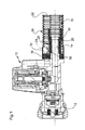
Figure 1 is a view in longitudinal section of a water stop device according to the invention, -
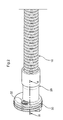
Figure 2 is a perspective view of some components of the water stop device ofFigure 1 , and -
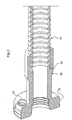
Figure 3 is a perspective view in section along the line III-III ofFigure 2 . - A water stop device for a domestic electrical appliance comprises a solenoid valve having a
body 10, aninlet pipe 12 and anoutlet pipe 14. A flexible innerwater flow tube 16 has aproximal end 18 facing adistal end 26 of theoutlet pipe 14. A flexibleouter safety tube 20 is arranged around theinner tube 16 so as to define, between thetubes annular air gap 22, in which may be housed an electric cable (not shown in the drawings) for supplying power to the solenoid valve. - Both the
inner tube 16 and theouter tube 20 are of corrugated type and are preferably made of polypropylene. - The
longitudinal axes 24 of theinner tube 16 and of theoutlet pipe 14 coincide and theproximal end 18 of theinner tube 16 and thedistal end 26 of theoutlet pipe 14 are associated with one another by means of atubular sleeve 28 arranged, sealed, coaxially on their exterior. - The
sleeve 28 is made of polymeric material and is preferably produced by means of a co-moulding technique which is known per se. According to this technique, theopposed ends inner tube 16 and of theoutlet pipe 14 are placed in a mould cavity into which there is then injected the molten polymeric material which, once solidified, assumes the shape of thesleeve 28 and encloses theends - Protruding radially from the proximal end of the
sleeve 28 is anannular flange 30, within a portion of which anaxial hole 32 is provided for the passage of an electric cable for supplying power to the solenoid valve. In this way it is possible to avoid having to use a further component functioning as a cable fairlead gasket, further reducing the cost of the water stop device. On the radially outermost circumferential surface of theflange 30 theproximal end 34 of the corrugatedouter tube 20 is further fitted. - A
resilient band 36 clamps an intermediate circumferential portion of thesleeve 28 against the portion ofoutlet pipe 14 arranged radially inside it, so as to minimise the risk of theinner tube 16 and thesleeve 28 becoming forcibly separated from theoutlet pipe 14 as a result of a pulling action. - Overall, owing to the use of the two tubes of
corrugated type tubes - Naturally, the principle of the invention remaining the same, the details of construction and forms of embodiment may be varied widely with respect to those described purely by way of example, without thereby departing from the scope claimed.
Claims (4)
- A water stop device for a domestic electrical appliance, comprising: a solenoid valve having a body (10), an inlet pipe (12) and an outlet pipe (14), a flexible inner water flow tube (16) having a proximal end (18) associated with said outlet pipe (14) and a flexible outer safety tube (20) arranged around the inner tube (16) so as to defme, between said inner tube (16) and outer tube (20), an annular air gap (22), wherein:- both the inner tube (16) and the outer tube (20) are of corrugated type,- the proximal end (18) of said inner tube (16) faces the distal end (26) of the outlet pipe (14) in such a way that the respective longitudinal axes (24) coincide, and said ends (18, 26) are associated with one another by means of a tubular sleeve (28) arranged, sealed, coaxially on their exterior,- protruding radially from the proximal end of said sleeve (28) is an annular flange (30), within a portion of which an axial hole (32) is provided for the passage of an electric cable for supplying power to the solenoid valve, and- the proximal end (34) of said outer tube (20) is fitted onto the radially outermost circumferential surface of said flange (30) of the sleeve (28).
- A device according to claim 1, wherein said corrugated inner tube (16) and outer tube (20) are made of polypropylene.
- A device according to claim 1, wherein said sleeve (28) is made of polymeric material and is produced by a co-moulding technique, by placing said opposed ends (18, 26) in a mould cavity and injecting therein the molten polymeric material which, once solidified, assumes the shape of the sleeve (28) and encloses said ends (18, 26) from the outside,
- A device according to any one of the preceding claims, wherein a resilient band (36) clamps an intermediate circumferential portion of said sleeve (28) against the portion of outlet pipe (14) arranged radially inside it.
Priority Applications (1)
| Application Number | Priority Date | Filing Date | Title |
|---|---|---|---|
| PL08150904T PL1955640T3 (en) | 2007-02-02 | 2008-01-31 | Improved water stop device |
Applications Claiming Priority (1)
| Application Number | Priority Date | Filing Date | Title |
|---|---|---|---|
| IT000075A ITTO20070075A1 (en) | 2007-02-02 | 2007-02-02 | PERFECT ACQUASTOP DEVICE |
Publications (3)
| Publication Number | Publication Date |
|---|---|
| EP1955640A2 EP1955640A2 (en) | 2008-08-13 |
| EP1955640A3 EP1955640A3 (en) | 2009-07-29 |
| EP1955640B1 true EP1955640B1 (en) | 2015-03-18 |
Family
ID=39521981
Family Applications (1)
| Application Number | Title | Priority Date | Filing Date |
|---|---|---|---|
| EP08150904.4A Not-in-force EP1955640B1 (en) | 2007-02-02 | 2008-01-31 | Improved water stop device |
Country Status (4)
| Country | Link |
|---|---|
| EP (1) | EP1955640B1 (en) |
| ES (1) | ES2539516T3 (en) |
| IT (1) | ITTO20070075A1 (en) |
| PL (1) | PL1955640T3 (en) |
Families Citing this family (2)
| Publication number | Priority date | Publication date | Assignee | Title |
|---|---|---|---|---|
| ITTO20130598A1 (en) * | 2013-07-16 | 2015-01-17 | Bitron Spa | LOADING AND / OR SAFETY DEVICE FOR ANTI-LINING FOR A WASHING MACHINE. |
| EP2947194B1 (en) * | 2014-05-22 | 2018-09-05 | Schlemmer Gmbh | Coupling assembly for a domestic appliance, device for a domestic appliance and domestic appliance |
Family Cites Families (6)
| Publication number | Priority date | Publication date | Assignee | Title |
|---|---|---|---|---|
| GB1039515A (en) * | 1962-07-24 | 1966-08-17 | Power Aux Ies Ltd | Improvements in or relating to flexible pressure tubes and ducts |
| JP3261969B2 (en) * | 1996-02-29 | 2002-03-04 | 豊田合成株式会社 | Hose and manufacturing method |
| IT1308378B1 (en) * | 1999-02-19 | 2001-12-17 | Eltek Spa | LIQUID DETECTOR AND ANTI-FLOODING SAFETY DEVICE USING SUCH DETECTOR. |
| IT1310721B1 (en) * | 1999-09-15 | 2002-02-22 | Eltek Spa | SENSOR FOR HYDRAULIC APPLIANCE DEVICES, IN PARTICULAR WASHING MACHINES, AND HYDRAULIC DEVICE INTEGRATING SUCH SENSOR |
| DE20314718U1 (en) * | 2003-09-23 | 2003-12-18 | Fränkische Rohrwerke Gebr. Kirchner GmbH + Co. KG | Water pipe connection to a household implement, e.g. a dishwasher, comprises a cylindrical outer mantle and a cylindrical inner mantle with a corrugated section |
| ITTO20050876A1 (en) * | 2005-12-15 | 2007-06-16 | Eltek Spa | SAFETY DEVICE ANTI-SLIPPING FOR APPLIANCES, IN PARTICULAR WASHING MACHINES |
-
2007
- 2007-02-02 IT IT000075A patent/ITTO20070075A1/en unknown
-
2008
- 2008-01-31 PL PL08150904T patent/PL1955640T3/en unknown
- 2008-01-31 EP EP08150904.4A patent/EP1955640B1/en not_active Not-in-force
- 2008-01-31 ES ES08150904.4T patent/ES2539516T3/en active Active
Also Published As
| Publication number | Publication date |
|---|---|
| PL1955640T3 (en) | 2015-08-31 |
| ITTO20070075A1 (en) | 2008-08-03 |
| ES2539516T3 (en) | 2015-07-01 |
| EP1955640A2 (en) | 2008-08-13 |
| EP1955640A3 (en) | 2009-07-29 |
Similar Documents
| Publication | Publication Date | Title |
|---|---|---|
| ES2366746T3 (en) | INTEGRATED ASSEMBLY OF HOSE AND COUPLING OF POLYMER MATERIAL AND METHOD OF MANUFACTURING IT. | |
| ES2685769T3 (en) | Flood safety device for home appliances, particularly for washing machines | |
| US9206934B2 (en) | Heated hose assembly | |
| EA017132B8 (en) | End fitting for composite hose | |
| CN103180538B (en) | For regulating the polymeric film of oil extraction pipeline | |
| KR101705845B1 (en) | Descaling devices for piping | |
| EP1955640A2 (en) | Improved water stop device | |
| CN102959302B (en) | End face structure of reinforced hose and method for treating end face of hose, and coating cap | |
| JP4503990B2 (en) | Flexible hose | |
| CA2573913A1 (en) | Gripping tool | |
| EP3715692B1 (en) | A non-demountable connection system for connecting a flexible hose to a hydraulic device | |
| ITMI20102206A1 (en) | DEVICE FOR CONNECTING DERIVATION PIPES TO A MAIN PIPE IN IRRIGATION SYSTEMS | |
| KR200484757Y1 (en) | Flexible hose for kitchen | |
| JP2006002911A (en) | Tightening structure of mouthpiece for water supply hose | |
| IL124076A (en) | Protection device for flexible hoses | |
| KR101509654B1 (en) | flexible hose | |
| ITMI970633U1 (en) | WATER SUPPLY PIPE PERFECTLY DONE IN PARTICULAR FOR HOUSEHOLD APPLIANCES | |
| EP2837869B1 (en) | Hose coupling, hose part and hose and pump system provided therewith, and method for coupling hose parts | |
| ITMI20002416A1 (en) | FITTING FOR INTERNALLY COATED PIPES AND PROCEDURE FOR ITS INSTALLATION | |
| EP3754241B1 (en) | Central insertion connector | |
| EP2927551B1 (en) | Connection sleeve and manifold cabinet | |
| KR200283875Y1 (en) | Sealing structure a hose | |
| EP3660379B1 (en) | Connecting structure of a multilayer tube, particularly for chemical and food-related fluids | |
| KR20100074618A (en) | Pipe for drinking water having soft film for protection | |
| ITTO20030168U1 (en) | IMMERSION DEVICE FOR HEATING A LIQUID. |
Legal Events
| Date | Code | Title | Description |
|---|---|---|---|
| PUAI | Public reference made under article 153(3) epc to a published international application that has entered the european phase |
Free format text: ORIGINAL CODE: 0009012 |
|
| AK | Designated contracting states |
Kind code of ref document: A2 Designated state(s): AT BE BG CH CY CZ DE DK EE ES FI FR GB GR HR HU IE IS IT LI LT LU LV MC MT NL NO PL PT RO SE SI SK TR |
|
| AX | Request for extension of the european patent |
Extension state: AL BA MK RS |
|
| RIN1 | Information on inventor provided before grant (corrected) |
Inventor name: BRIGNONE, ENZO Inventor name: RIVERO, DAVIDE |
|
| PUAL | Search report despatched |
Free format text: ORIGINAL CODE: 0009013 |
|
| AK | Designated contracting states |
Kind code of ref document: A3 Designated state(s): AT BE BG CH CY CZ DE DK EE ES FI FR GB GR HR HU IE IS IT LI LT LU LV MC MT NL NO PL PT RO SE SI SK TR |
|
| AX | Request for extension of the european patent |
Extension state: AL BA MK RS |
|
| 17P | Request for examination filed |
Effective date: 20100127 |
|
| 17Q | First examination report despatched |
Effective date: 20100219 |
|
| AKX | Designation fees paid |
Designated state(s): DE ES PL |
|
| GRAJ | Information related to disapproval of communication of intention to grant by the applicant or resumption of examination proceedings by the epo deleted |
Free format text: ORIGINAL CODE: EPIDOSDIGR1 |
|
| GRAP | Despatch of communication of intention to grant a patent |
Free format text: ORIGINAL CODE: EPIDOSNIGR1 |
|
| GRAP | Despatch of communication of intention to grant a patent |
Free format text: ORIGINAL CODE: EPIDOSNIGR1 |
|
| INTG | Intention to grant announced |
Effective date: 20141001 |
|
| GRAS | Grant fee paid |
Free format text: ORIGINAL CODE: EPIDOSNIGR3 |
|
| GRAA | (expected) grant |
Free format text: ORIGINAL CODE: 0009210 |
|
| AK | Designated contracting states |
Kind code of ref document: B1 Designated state(s): DE ES PL |
|
| REG | Reference to a national code |
Ref country code: DE Ref legal event code: R096 Ref document number: 602008037171 Country of ref document: DE Effective date: 20150430 |
|
| REG | Reference to a national code |
Ref country code: ES Ref legal event code: FG2A Ref document number: 2539516 Country of ref document: ES Kind code of ref document: T3 Effective date: 20150701 |
|
| REG | Reference to a national code |
Ref country code: PL Ref legal event code: T3 |
|
| REG | Reference to a national code |
Ref country code: DE Ref legal event code: R026 Ref document number: 602008037171 Country of ref document: DE |
|
| PLBI | Opposition filed |
Free format text: ORIGINAL CODE: 0009260 |
|
| PLAX | Notice of opposition and request to file observation + time limit sent |
Free format text: ORIGINAL CODE: EPIDOSNOBS2 |
|
| 26 | Opposition filed |
Opponent name: SCHLEMMER GMBH Effective date: 20151218 |
|
| PLCK | Communication despatched that opposition was rejected |
Free format text: ORIGINAL CODE: EPIDOSNREJ1 |
|
| STAA | Information on the status of an ep patent application or granted ep patent |
Free format text: STATUS: THE PATENT HAS BEEN GRANTED |
|
| REG | Reference to a national code |
Ref country code: DE Ref legal event code: R100 Ref document number: 602008037171 Country of ref document: DE |
|
| PLBN | Opposition rejected |
Free format text: ORIGINAL CODE: 0009273 |
|
| STAA | Information on the status of an ep patent application or granted ep patent |
Free format text: STATUS: OPPOSITION REJECTED |
|
| 27O | Opposition rejected |
Effective date: 20170929 |
|
| PGFP | Annual fee paid to national office [announced via postgrant information from national office to epo] |
Ref country code: PL Payment date: 20171218 Year of fee payment: 11 |
|
| PGFP | Annual fee paid to national office [announced via postgrant information from national office to epo] |
Ref country code: ES Payment date: 20180201 Year of fee payment: 11 |
|
| PGFP | Annual fee paid to national office [announced via postgrant information from national office to epo] |
Ref country code: DE Payment date: 20180329 Year of fee payment: 11 |
|
| REG | Reference to a national code |
Ref country code: DE Ref legal event code: R119 Ref document number: 602008037171 Country of ref document: DE |
|
| PG25 | Lapsed in a contracting state [announced via postgrant information from national office to epo] |
Ref country code: DE Free format text: LAPSE BECAUSE OF NON-PAYMENT OF DUE FEES Effective date: 20190801 |
|
| REG | Reference to a national code |
Ref country code: ES Ref legal event code: FD2A Effective date: 20200310 |
|
| PG25 | Lapsed in a contracting state [announced via postgrant information from national office to epo] |
Ref country code: ES Free format text: LAPSE BECAUSE OF NON-PAYMENT OF DUE FEES Effective date: 20190201 |
|
| PG25 | Lapsed in a contracting state [announced via postgrant information from national office to epo] |
Ref country code: PL Free format text: LAPSE BECAUSE OF NON-PAYMENT OF DUE FEES Effective date: 20190131 |