EP1954469B1 - Method for manufacturing an antenna radome from composite materials in continuous action - Google Patents
Method for manufacturing an antenna radome from composite materials in continuous action Download PDFInfo
- Publication number
- EP1954469B1 EP1954469B1 EP06778543.6A EP06778543A EP1954469B1 EP 1954469 B1 EP1954469 B1 EP 1954469B1 EP 06778543 A EP06778543 A EP 06778543A EP 1954469 B1 EP1954469 B1 EP 1954469B1
- Authority
- EP
- European Patent Office
- Prior art keywords
- reflective layer
- continuous
- wall
- radome
- set forth
- Prior art date
- Legal status (The legal status is an assumption and is not a legal conclusion. Google has not performed a legal analysis and makes no representation as to the accuracy of the status listed.)
- Active
Links
Images

Classifications
-
- B—PERFORMING OPERATIONS; TRANSPORTING
- B29—WORKING OF PLASTICS; WORKING OF SUBSTANCES IN A PLASTIC STATE IN GENERAL
- B29C—SHAPING OR JOINING OF PLASTICS; SHAPING OF MATERIAL IN A PLASTIC STATE, NOT OTHERWISE PROVIDED FOR; AFTER-TREATMENT OF THE SHAPED PRODUCTS, e.g. REPAIRING
- B29C70/00—Shaping composites, i.e. plastics material comprising reinforcements, fillers or preformed parts, e.g. inserts
- B29C70/04—Shaping composites, i.e. plastics material comprising reinforcements, fillers or preformed parts, e.g. inserts comprising reinforcements only, e.g. self-reinforcing plastics
- B29C70/28—Shaping operations therefor
- B29C70/40—Shaping or impregnating by compression not applied
- B29C70/50—Shaping or impregnating by compression not applied for producing articles of indefinite length, e.g. prepregs, sheet moulding compounds [SMC] or cross moulding compounds [XMC]
- B29C70/52—Pultrusion, i.e. forming and compressing by continuously pulling through a die
-
- B—PERFORMING OPERATIONS; TRANSPORTING
- B29—WORKING OF PLASTICS; WORKING OF SUBSTANCES IN A PLASTIC STATE IN GENERAL
- B29C—SHAPING OR JOINING OF PLASTICS; SHAPING OF MATERIAL IN A PLASTIC STATE, NOT OTHERWISE PROVIDED FOR; AFTER-TREATMENT OF THE SHAPED PRODUCTS, e.g. REPAIRING
- B29C70/00—Shaping composites, i.e. plastics material comprising reinforcements, fillers or preformed parts, e.g. inserts
- B29C70/04—Shaping composites, i.e. plastics material comprising reinforcements, fillers or preformed parts, e.g. inserts comprising reinforcements only, e.g. self-reinforcing plastics
- B29C70/06—Fibrous reinforcements only
- B29C70/08—Fibrous reinforcements only comprising combinations of different forms of fibrous reinforcements incorporated in matrix material, forming one or more layers, and with or without non-reinforced layers
- B29C70/088—Fibrous reinforcements only comprising combinations of different forms of fibrous reinforcements incorporated in matrix material, forming one or more layers, and with or without non-reinforced layers and with one or more layers of non-plastics material or non-specified material, e.g. supports
-
- B—PERFORMING OPERATIONS; TRANSPORTING
- B29—WORKING OF PLASTICS; WORKING OF SUBSTANCES IN A PLASTIC STATE IN GENERAL
- B29C—SHAPING OR JOINING OF PLASTICS; SHAPING OF MATERIAL IN A PLASTIC STATE, NOT OTHERWISE PROVIDED FOR; AFTER-TREATMENT OF THE SHAPED PRODUCTS, e.g. REPAIRING
- B29C48/00—Extrusion moulding, i.e. expressing the moulding material through a die or nozzle which imparts the desired form; Apparatus therefor
- B29C48/03—Extrusion moulding, i.e. expressing the moulding material through a die or nozzle which imparts the desired form; Apparatus therefor characterised by the shape of the extruded material at extrusion
- B29C48/09—Articles with cross-sections having partially or fully enclosed cavities, e.g. pipes or channels
-
- B—PERFORMING OPERATIONS; TRANSPORTING
- B29—WORKING OF PLASTICS; WORKING OF SUBSTANCES IN A PLASTIC STATE IN GENERAL
- B29C—SHAPING OR JOINING OF PLASTICS; SHAPING OF MATERIAL IN A PLASTIC STATE, NOT OTHERWISE PROVIDED FOR; AFTER-TREATMENT OF THE SHAPED PRODUCTS, e.g. REPAIRING
- B29C48/00—Extrusion moulding, i.e. expressing the moulding material through a die or nozzle which imparts the desired form; Apparatus therefor
- B29C48/03—Extrusion moulding, i.e. expressing the moulding material through a die or nozzle which imparts the desired form; Apparatus therefor characterised by the shape of the extruded material at extrusion
- B29C48/12—Articles with an irregular circumference when viewed in cross-section, e.g. window profiles
-
- B—PERFORMING OPERATIONS; TRANSPORTING
- B29—WORKING OF PLASTICS; WORKING OF SUBSTANCES IN A PLASTIC STATE IN GENERAL
- B29C—SHAPING OR JOINING OF PLASTICS; SHAPING OF MATERIAL IN A PLASTIC STATE, NOT OTHERWISE PROVIDED FOR; AFTER-TREATMENT OF THE SHAPED PRODUCTS, e.g. REPAIRING
- B29C70/00—Shaping composites, i.e. plastics material comprising reinforcements, fillers or preformed parts, e.g. inserts
- B29C70/04—Shaping composites, i.e. plastics material comprising reinforcements, fillers or preformed parts, e.g. inserts comprising reinforcements only, e.g. self-reinforcing plastics
- B29C70/28—Shaping operations therefor
- B29C70/40—Shaping or impregnating by compression not applied
- B29C70/50—Shaping or impregnating by compression not applied for producing articles of indefinite length, e.g. prepregs, sheet moulding compounds [SMC] or cross moulding compounds [XMC]
- B29C70/52—Pultrusion, i.e. forming and compressing by continuously pulling through a die
- B29C70/521—Pultrusion, i.e. forming and compressing by continuously pulling through a die and impregnating the reinforcement before the die
-
- H—ELECTRICITY
- H01—ELECTRIC ELEMENTS
- H01Q—ANTENNAS, i.e. RADIO AERIALS
- H01Q1/00—Details of, or arrangements associated with, antennas
- H01Q1/42—Housings not intimately mechanically associated with radiating elements, e.g. radome
-
- H—ELECTRICITY
- H05—ELECTRIC TECHNIQUES NOT OTHERWISE PROVIDED FOR
- H05K—PRINTED CIRCUITS; CASINGS OR CONSTRUCTIONAL DETAILS OF ELECTRIC APPARATUS; MANUFACTURE OF ASSEMBLAGES OF ELECTRICAL COMPONENTS
- H05K9/00—Screening of apparatus or components against electric or magnetic fields
-
- B—PERFORMING OPERATIONS; TRANSPORTING
- B29—WORKING OF PLASTICS; WORKING OF SUBSTANCES IN A PLASTIC STATE IN GENERAL
- B29C—SHAPING OR JOINING OF PLASTICS; SHAPING OF MATERIAL IN A PLASTIC STATE, NOT OTHERWISE PROVIDED FOR; AFTER-TREATMENT OF THE SHAPED PRODUCTS, e.g. REPAIRING
- B29C48/00—Extrusion moulding, i.e. expressing the moulding material through a die or nozzle which imparts the desired form; Apparatus therefor
- B29C48/022—Extrusion moulding, i.e. expressing the moulding material through a die or nozzle which imparts the desired form; Apparatus therefor characterised by the choice of material
-
- B—PERFORMING OPERATIONS; TRANSPORTING
- B29—WORKING OF PLASTICS; WORKING OF SUBSTANCES IN A PLASTIC STATE IN GENERAL
- B29C—SHAPING OR JOINING OF PLASTICS; SHAPING OF MATERIAL IN A PLASTIC STATE, NOT OTHERWISE PROVIDED FOR; AFTER-TREATMENT OF THE SHAPED PRODUCTS, e.g. REPAIRING
- B29C48/00—Extrusion moulding, i.e. expressing the moulding material through a die or nozzle which imparts the desired form; Apparatus therefor
- B29C48/03—Extrusion moulding, i.e. expressing the moulding material through a die or nozzle which imparts the desired form; Apparatus therefor characterised by the shape of the extruded material at extrusion
- B29C48/07—Flat, e.g. panels
-
- B—PERFORMING OPERATIONS; TRANSPORTING
- B29—WORKING OF PLASTICS; WORKING OF SUBSTANCES IN A PLASTIC STATE IN GENERAL
- B29C—SHAPING OR JOINING OF PLASTICS; SHAPING OF MATERIAL IN A PLASTIC STATE, NOT OTHERWISE PROVIDED FOR; AFTER-TREATMENT OF THE SHAPED PRODUCTS, e.g. REPAIRING
- B29C48/00—Extrusion moulding, i.e. expressing the moulding material through a die or nozzle which imparts the desired form; Apparatus therefor
- B29C48/25—Component parts, details or accessories; Auxiliary operations
- B29C48/30—Extrusion nozzles or dies
- B29C48/32—Extrusion nozzles or dies with annular openings, e.g. for forming tubular articles
-
- B—PERFORMING OPERATIONS; TRANSPORTING
- B29—WORKING OF PLASTICS; WORKING OF SUBSTANCES IN A PLASTIC STATE IN GENERAL
- B29K—INDEXING SCHEME ASSOCIATED WITH SUBCLASSES B29B, B29C OR B29D, RELATING TO MOULDING MATERIALS OR TO MATERIALS FOR MOULDS, REINFORCEMENTS, FILLERS OR PREFORMED PARTS, e.g. INSERTS
- B29K2105/00—Condition, form or state of moulded material or of the material to be shaped
- B29K2105/06—Condition, form or state of moulded material or of the material to be shaped containing reinforcements, fillers or inserts
-
- B—PERFORMING OPERATIONS; TRANSPORTING
- B29—WORKING OF PLASTICS; WORKING OF SUBSTANCES IN A PLASTIC STATE IN GENERAL
- B29K—INDEXING SCHEME ASSOCIATED WITH SUBCLASSES B29B, B29C OR B29D, RELATING TO MOULDING MATERIALS OR TO MATERIALS FOR MOULDS, REINFORCEMENTS, FILLERS OR PREFORMED PARTS, e.g. INSERTS
- B29K2105/00—Condition, form or state of moulded material or of the material to be shaped
- B29K2105/06—Condition, form or state of moulded material or of the material to be shaped containing reinforcements, fillers or inserts
- B29K2105/20—Inserts
- B29K2105/206—Meshes, lattices or nets
-
- B—PERFORMING OPERATIONS; TRANSPORTING
- B29—WORKING OF PLASTICS; WORKING OF SUBSTANCES IN A PLASTIC STATE IN GENERAL
- B29K—INDEXING SCHEME ASSOCIATED WITH SUBCLASSES B29B, B29C OR B29D, RELATING TO MOULDING MATERIALS OR TO MATERIALS FOR MOULDS, REINFORCEMENTS, FILLERS OR PREFORMED PARTS, e.g. INSERTS
- B29K2705/00—Use of metals, their alloys or their compounds, for preformed parts, e.g. for inserts
-
- B—PERFORMING OPERATIONS; TRANSPORTING
- B29—WORKING OF PLASTICS; WORKING OF SUBSTANCES IN A PLASTIC STATE IN GENERAL
- B29K—INDEXING SCHEME ASSOCIATED WITH SUBCLASSES B29B, B29C OR B29D, RELATING TO MOULDING MATERIALS OR TO MATERIALS FOR MOULDS, REINFORCEMENTS, FILLERS OR PREFORMED PARTS, e.g. INSERTS
- B29K2707/00—Use of elements other than metals for preformed parts, e.g. for inserts
- B29K2707/04—Carbon
-
- B—PERFORMING OPERATIONS; TRANSPORTING
- B29—WORKING OF PLASTICS; WORKING OF SUBSTANCES IN A PLASTIC STATE IN GENERAL
- B29K—INDEXING SCHEME ASSOCIATED WITH SUBCLASSES B29B, B29C OR B29D, RELATING TO MOULDING MATERIALS OR TO MATERIALS FOR MOULDS, REINFORCEMENTS, FILLERS OR PREFORMED PARTS, e.g. INSERTS
- B29K2995/00—Properties of moulding materials, reinforcements, fillers, preformed parts or moulds
- B29K2995/0003—Properties of moulding materials, reinforcements, fillers, preformed parts or moulds having particular electrical or magnetic properties, e.g. piezoelectric
- B29K2995/0005—Conductive
-
- B—PERFORMING OPERATIONS; TRANSPORTING
- B29—WORKING OF PLASTICS; WORKING OF SUBSTANCES IN A PLASTIC STATE IN GENERAL
- B29K—INDEXING SCHEME ASSOCIATED WITH SUBCLASSES B29B, B29C OR B29D, RELATING TO MOULDING MATERIALS OR TO MATERIALS FOR MOULDS, REINFORCEMENTS, FILLERS OR PREFORMED PARTS, e.g. INSERTS
- B29K2995/00—Properties of moulding materials, reinforcements, fillers, preformed parts or moulds
- B29K2995/0003—Properties of moulding materials, reinforcements, fillers, preformed parts or moulds having particular electrical or magnetic properties, e.g. piezoelectric
- B29K2995/0008—Magnetic or paramagnetic
-
- B—PERFORMING OPERATIONS; TRANSPORTING
- B29—WORKING OF PLASTICS; WORKING OF SUBSTANCES IN A PLASTIC STATE IN GENERAL
- B29L—INDEXING SCHEME ASSOCIATED WITH SUBCLASS B29C, RELATING TO PARTICULAR ARTICLES
- B29L2031/00—Other particular articles
- B29L2031/34—Electrical apparatus, e.g. sparking plugs or parts thereof
- B29L2031/3456—Antennas, e.g. radomes
Definitions
- the invention relates to a method for manufacturing an antenna radome from composite materials in continuous action by pultrusion technique, said method comprising pulling resin-wetted continuous fibers, mats or fabrics through one or more guides for preforming and then through a heated forming die and finally chopping up the continuous product for radomes of appropriate length.
- the invention relates also to a corresponding method for manufacturing a radome in continuous action by extrusion, said method comprising extruding paste of polymer or fiber-reinforced polymer through a forming die and finally chopping up the continuous product for radomes of appropriate length.
- Radomes are used, among other things, in conjunction with base station antennae and radar antennae in telecommunications and wireless communication for protecting the antenna (its emitters) from the effects of weather, for directing the radiation beam by means of a reflective layer, and as a support assembly for connections and other antenna accessories.
- base station antennae and radar antennae in telecommunications and wireless communication for protecting the antenna (its emitters) from the effects of weather, for directing the radiation beam by means of a reflective layer, and as a support assembly for connections and other antenna accessories.
- Patent publication FI-96751 discloses a method for manufacturing a radome by casting, such that a layer reflective of electromagnetic waves (i.e. electrically conductive) is cast onto the wall surface or within the wall of a radome. This prior art manufacturing method is tedious and inconvenient to practice.
- GB 2 142 782 A describes a method of producing a radome in accordance with the preamble of claim 5 having coaxial inner and outer cylinder shells formed by extrusion of plastics material.
- a circular polarising grid network is made by printing on to the outer surface of the cylinders. The polarising grid does not need mounting with regard to the cylinder cells. Nevertheless, a separate stage of printing is needed dafter manufacturing the cylinder cells.
- EP 0 802 033 A1 describes a method for providing electromagnetic shielding and diffusion barrier properties of an extruded multiple layer sheet of cylindrical shape.
- the electromagnetic shielding layer extends over the whole width or circumference of the multiple layer sheet in a complex extruded part to be used in building industry.
- the product is not applicable as a radome because the magnetic shielding layer is not designed for directing the radiation beam.
- An object of the invention is to provide a radome manufacturing method useful for avoiding or substantially mitigating the above problems.
- an object of the invention is to provide a radome manufacturing method of continuous action, which can be used for manufacturing lightweight antenna assemblies, wherein the number of components is reduced and functionality of the antenna is improved.
- Reinforced fibers e.g. glass fibers, which are continuous monofilament yarns 8, are pulled from drums 13 through a resin applicator 12. Resin-wetted fibers 8' are pulled further through a guide 10 and by way of an appropriately designed guiding die 7 into a heated mold 5 provided with a core 6.
- the mold 5 and the core 6 make up a forming die, i.e. the final shape of a profile to be formed is determined by the shape of the mold 5 and the core 6. It can be, as shown e.g. in fig. 2 , a circumferentially closed tubular section, having a flat rearward face, arcuate sides, and a slightly arcuate or partially flat forward face.
- the section shape can also be a flat bar or two separate U-sections, which after manufacturing are coupled by their edges to face each other for a tubular section.
- the guide 10 can be a comb guide, a pipe guide, a hollow guide or a combination of various guides.
- certain section shapes e.g. a flat section
- the wall thickness may vary within the range of 1-6 mm, typically within the range of 1,5-3,0 mm.
- a continuous product 2 obtained in the mold 5 is drawn by means of a pulling device 4 and the product is chopped up by a cutting saw 3 for radomes of desired length.
- the relative positions of materials supplied into the mold 5 are determined by the guide 10 and the guiding die 7.
- the layer 9, 9' reflective of electromagnetic radiation is passed in continuous action within a wall or onto the surface of a wall of the product 2 being produced in the forming die 5, 6 for an integral part of the wall. According to one preferred embodiment of the invention, this is performed by feeding the reflective layer 9, 9' as a continuous web or mat through or by means of the guide 10 and further the guiding die 7 to within the reinforced fibers, mats or fabrics 8' for replacing thereby some of the reinforcement 8' destined for a respective location, the wall thickness remaining substantially constant or not increasing at the same rate as the thickness of the reflective layer 9, 9'.
- adhesion can be enhanced by providing the radiation reflecting layer with a surface structuring, a fabric composition or a pattern of holes, designed not only for improving reflection properties but also for enhancing adhesion to resin.
- the adhesion to resin can also be improved by subjecting the reflective layer to a chemical surface treatment with silane and/or bonding agents, such as adhesives, or by subjecting the reflective layer to a physical surface treatment with an electric discharge or corona method, a flame treatment or a plasma treatment.
- silane and/or bonding agents such as adhesives
- the reflective layer 9, 9' is a thin metal foil, sheet or mat, having its surface provided with a lattice-like striation or raster 9s.
- the reflective layer is a metal mat or fabric with a mesh-like structure.
- the reflective layer can be made at least partially from thin wires or metallized fibers.
- the reflective layer 9, 9' is a non-woven mat, which is coated or treated with a conductive material. If the reflective layer is thin, it may additionally include a base layer, e.g. a reinforced plastic laminate, a paper or plastic sheet.
- the reflective layer 9 can be bonded or applied to the surface of a web or mat, such as a fiberglass mat, functioning as the radome's wall material, prior to its passage into the guide 10.
- the conductive layer is a metal foil, sheet or mat, with a pattern of holes therein.
- the holes can be made by drilling and/or punching.
- the holes may vary in terms of size and shape.
- Strength and adhesion can also be improved by having the material, which is displaced out of the way of a hole in the hole-cutting process, deflected to provide an engagement lip. Strength can be improved, especially when the resin is able to penetrate at least sporadically through the reflective layer from the holes or fabric structure. This is beneficial when the radiation reflecting layer 9, 9' is passed in its entirety within the wall of a developing product for an integral component thereof.
- the radiation reflecting layer may also be in attachment to the surface of a radome wall whereby, for adhesion, the resin is in penetrated position within the reflective layer's surface structure or through the holes across the reflective layer's entire thickness, at least sporadically.
- the mutual adhesion of a reflection layer and other composite material can also be improved by the selection of a resin used as a bonding agent.
- the resin is one or several of the following: polyester, vinyl ester, epoxy or polyurethane.
- thermo- or thermosetting plastics common in the manufacture of reinforced plastics may also be relevant and those can be thermoplasticizing or thermosetting according to which manufacturing process is used.
- the combined effect of the reflection layer's surface structure, fabric composition or hole pattern and the selection of a resin material enables providing a strength which is sufficient, even if the wall thickness is not increased, at least substantially, at the location of a reflection layer.
- a method of the invention is readily applicable for supplying various circumferential regions of a radome with a range of various reflection layers and thereby it is possible to influence the shape of a reflection beam, such that the beam reshapes gradually without sharp lines or stepwise.
- the reflection layer 9 embedded within the base of a radome can be otherwise reflective than the reflectors 9' embedded within the side walls, the latter being possibly more transmissive to radiation.
- Some regions can be provided with a thicker or two or more overlying reflection layers, having resin or some other separately applied bonding agent therebetween.
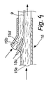
- Fig. 4 illustrates how continuous manufacturing can be performed also by extrusion, whereby a paste consisting of polymers or fiber-reinforced polymers is extruded through a forming die 15.
- a reflection layer 9, which possesses properties as described above, is delivered as a continuous web or mat to the forming die 15 for replacing, the same way as in the foregoing exemplary embodiment, some of the paste located in this particular region, such that the wall thickness of a resulting product does not grow, at least not substantially.
- the above-described methods are applicable also in this case.
- an extrusion die 15 is preferably implemented in such a way that the supply of materials can be effected in a two-stage fashion (conduits 15a and 15b).
- the conductive layer 9 must have a separate feeding point 15c and a special forming guide 15d inside the die 15 in a location whereat the rest of the composite paste is still in a plastic state. If the feed of materials is performed in a single stage, the forming guide must be located immediately upstream of the die.
- the reflective layer 9 comprises some electrically conductive material, typically a metal such as steel, copper, aluminum, zinc, iron, nickel, bronze, magnesium or the like. Also carbon fiber and/or conductive polymers (PAN) can be used at least as a part of the reflective layer 9, 9'.
- PAN conductive polymers
- an antenna element 16 ( fig. 2 ) can also be manufactured by a continuous process as a permanent component in the wall of a radome 1.
- the antenna element 16 is a conductive layer, which is patterned to form an active antenna element and placed on a wall of the radome opposite to the reflective layer 9.
- the conductive layers 9 and 16 are spaced by a distance which is typically 1/2 wavelength.
- the legs of two U-sections can be engageable with each other in various adjustable overlaps. It is also possible to feed flexible circuit boards in a continuous manufacturing process as part of the radome's wall structure. The same applies to a circuit board blank, which can be patterned afterwards by milling or etching.
- Conductive layers or circuit boards delivered by a method of the invention can also be used as feeding assemblies for the circuit elements of an antenna or as regulation and filter assemblies for switching a direction or wave ranges. Consequently, antenna radomes manufactured by the method can be used e.g. as directive radar antennae, which only use electronics to switch the direction thereof.
Landscapes
- Engineering & Computer Science (AREA)
- Mechanical Engineering (AREA)
- Chemical & Material Sciences (AREA)
- Composite Materials (AREA)
- Microelectronics & Electronic Packaging (AREA)
- Details Of Aerials (AREA)
- Aerials With Secondary Devices (AREA)
Description
- The invention relates to a method for manufacturing an antenna radome from composite materials in continuous action by pultrusion technique, said method comprising pulling resin-wetted continuous fibers, mats or fabrics through one or more guides for preforming and then through a heated forming die and finally chopping up the continuous product for radomes of appropriate length.
- The invention relates also to a corresponding method for manufacturing a radome in continuous action by extrusion, said method comprising extruding paste of polymer or fiber-reinforced polymer through a forming die and finally chopping up the continuous product for radomes of appropriate length.
- Radomes are used, among other things, in conjunction with base station antennae and radar antennae in telecommunications and wireless communication for protecting the antenna (its emitters) from the effects of weather, for directing the radiation beam by means of a reflective layer, and as a support assembly for connections and other antenna accessories. Regarding the prior art, reference can be made e.g. to patent publication
EP-0 916 169 B1 . - Patent publication
FI-96751 - It is also prior known to manufacture a casing component for a radome in continuous action by a pultrusion method. Radiation reflecting layers are separately applied at a later stage outside or inside such a radome. Thus, the resulting unit will be heavy, in addition to which the reflective layer is exposed to corrosion. Assembling a radome made up by several components involves also extra labor and costs.
-
GB 2 142 782 A claim 5 having coaxial inner and outer cylinder shells formed by extrusion of plastics material. A circular polarising grid network is made by printing on to the outer surface of the cylinders. The polarising grid does not need mounting with regard to the cylinder cells. Nevertheless, a separate stage of printing is needed dafter manufacturing the cylinder cells. -
EP 0 802 033 A1 describes a method for providing electromagnetic shielding and diffusion barrier properties of an extruded multiple layer sheet of cylindrical shape. The electromagnetic shielding layer extends over the whole width or circumference of the multiple layer sheet in a complex extruded part to be used in building industry. The product is not applicable as a radome because the magnetic shielding layer is not designed for directing the radiation beam. - An object of the invention is to provide a radome manufacturing method useful for avoiding or substantially mitigating the above problems. Specifically, an object of the invention is to provide a radome manufacturing method of continuous action, which can be used for manufacturing lightweight antenna assemblies, wherein the number of components is reduced and functionality of the antenna is improved.
- This object is accomplished with the invention, as defined in the appended
claims 1 and 5. Preferred ways of implementing the invention are set forth in the dependent claims. - A method of the invention will now be described in more detail by way of example with reference to the accompanying drawing, in which
- Fig. 1
- shows schematically various steps in a manufacturing method or pultrusion according to one embodiment of the invention, and an apparatus for carrying out the method;
- Fig. 2
- shows in a larger-scale perspective view one exemplary embodiment for a radome manufactured with a method of the invention;
- Fig. 3
- shows one exemplary embodiment for a reflective layer 9 (9') for use in a radome of the invention;
- Fig. 4
- shows schematically the implementation of a manufacturing method or extrusion according to a second embodiment of the invention.
- Reinforced fibers, e.g. glass fibers, which are
continuous monofilament yarns 8, are pulled fromdrums 13 through aresin applicator 12. Resin-wetted fibers 8' are pulled further through aguide 10 and by way of an appropriately designed guiding die 7 into a heatedmold 5 provided with a core 6. Themold 5 and the core 6 make up a forming die, i.e. the final shape of a profile to be formed is determined by the shape of themold 5 and the core 6. It can be, as shown e.g. infig. 2 , a circumferentially closed tubular section, having a flat rearward face, arcuate sides, and a slightly arcuate or partially flat forward face. The section shape can also be a flat bar or two separate U-sections, which after manufacturing are coupled by their edges to face each other for a tubular section. Depending on the section shape and employed materials, theguide 10 can be a comb guide, a pipe guide, a hollow guide or a combination of various guides. With certain section shapes (e.g. a flat section), there is no need for the core 6, whereby themold 5 functions also as a forming die. The wall thickness may vary within the range of 1-6 mm, typically within the range of 1,5-3,0 mm. A continuous product 2 obtained in themold 5 is drawn by means of a pulling device 4 and the product is chopped up by a cutting saw 3 for radomes of desired length. - The relative positions of materials supplied into the
mold 5 are determined by theguide 10 and the guidingdie 7. - What is new about the invention is that the
layer 9, 9' reflective of electromagnetic radiation is passed in continuous action within a wall or onto the surface of a wall of the product 2 being produced in the forming die 5, 6 for an integral part of the wall. According to one preferred embodiment of the invention, this is performed by feeding thereflective layer 9, 9' as a continuous web or mat through or by means of theguide 10 and further the guidingdie 7 to within the reinforced fibers, mats or fabrics 8' for replacing thereby some of the reinforcement 8' destined for a respective location, the wall thickness remaining substantially constant or not increasing at the same rate as the thickness of thereflective layer 9, 9'. In order to enable this without compromising strength, it has been discovered in a preferred embodiment of the invention that adhesion can be enhanced by providing the radiation reflecting layer with a surface structuring, a fabric composition or a pattern of holes, designed not only for improving reflection properties but also for enhancing adhesion to resin. The adhesion to resin can also be improved by subjecting the reflective layer to a chemical surface treatment with silane and/or bonding agents, such as adhesives, or by subjecting the reflective layer to a physical surface treatment with an electric discharge or corona method, a flame treatment or a plasma treatment. One or more of these adhesion enhancing techniques can be involved. - According to one embodiment of the invention, the
reflective layer 9, 9' is a thin metal foil, sheet or mat, having its surface provided with a lattice-like striation orraster 9s. According to a second embodiment of the invention, the reflective layer is a metal mat or fabric with a mesh-like structure. The reflective layer can be made at least partially from thin wires or metallized fibers. According to a third embodiment of the invention, thereflective layer 9, 9' is a non-woven mat, which is coated or treated with a conductive material. If the reflective layer is thin, it may additionally include a base layer, e.g. a reinforced plastic laminate, a paper or plastic sheet. Thereflective layer 9 can be bonded or applied to the surface of a web or mat, such as a fiberglass mat, functioning as the radome's wall material, prior to its passage into theguide 10. - According to a fourth embodiment of the invention, the conductive layer is a metal foil, sheet or mat, with a pattern of holes therein. The holes can be made by drilling and/or punching. The holes may vary in terms of size and shape. Strength and adhesion can also be improved by having the material, which is displaced out of the way of a hole in the hole-cutting process, deflected to provide an engagement lip. Strength can be improved, especially when the resin is able to penetrate at least sporadically through the reflective layer from the holes or fabric structure. This is beneficial when the
radiation reflecting layer 9, 9' is passed in its entirety within the wall of a developing product for an integral component thereof. However, the radiation reflecting layer may also be in attachment to the surface of a radome wall whereby, for adhesion, the resin is in penetrated position within the reflective layer's surface structure or through the holes across the reflective layer's entire thickness, at least sporadically. - The mutual adhesion of a reflection layer and other composite material can also be improved by the selection of a resin used as a bonding agent. Thus, the resin is one or several of the following: polyester, vinyl ester, epoxy or polyurethane. Naturally, all other thermo- or thermosetting plastics common in the manufacture of reinforced plastics may also be relevant and those can be thermoplasticizing or thermosetting according to which manufacturing process is used.
- The combined effect of the reflection layer's surface structure, fabric composition or hole pattern and the selection of a resin material enables providing a strength which is sufficient, even if the wall thickness is not increased, at least substantially, at the location of a reflection layer.
- A method of the invention is readily applicable for supplying various circumferential regions of a radome with a range of various reflection layers and thereby it is possible to influence the shape of a reflection beam, such that the beam reshapes gradually without sharp lines or stepwise. In the case of
fig. 2 , thereflection layer 9 embedded within the base of a radome can be otherwise reflective than the reflectors 9' embedded within the side walls, the latter being possibly more transmissive to radiation. Some regions can be provided with a thicker or two or more overlying reflection layers, having resin or some other separately applied bonding agent therebetween. - The invention is not limited to the foregoing exemplary embodiment, which describes manufacturing performed by a pultrusion method.
Fig. 4 illustrates how continuous manufacturing can be performed also by extrusion, whereby a paste consisting of polymers or fiber-reinforced polymers is extruded through a formingdie 15. Areflection layer 9, which possesses properties as described above, is delivered as a continuous web or mat to the formingdie 15 for replacing, the same way as in the foregoing exemplary embodiment, some of the paste located in this particular region, such that the wall thickness of a resulting product does not grow, at least not substantially. In view of enhancing adhesion of thereflective layer 9, the above-described methods are applicable also in this case. - In the context of an extrusion method, the design of an extrusion die 15 is preferably implemented in such a way that the supply of materials can be effected in a two-stage fashion (
conduits conductive layer 9 must have aseparate feeding point 15c and a special formingguide 15d inside the die 15 in a location whereat the rest of the composite paste is still in a plastic state. If the feed of materials is performed in a single stage, the forming guide must be located immediately upstream of the die. - The
reflective layer 9 comprises some electrically conductive material, typically a metal such as steel, copper, aluminum, zinc, iron, nickel, bronze, magnesium or the like. Also carbon fiber and/or conductive polymers (PAN) can be used at least as a part of thereflective layer 9, 9'. - It is also feasible to construct the wall of a radome in its entire or partial thickness from carbon-fiber reinforced polymer, thus establishing the reflective layer.
- In a preferred embodiment of the invention, an antenna element 16 (
fig. 2 ) can also be manufactured by a continuous process as a permanent component in the wall of a radome 1. Corresponding in design to thereflective layer 9, theantenna element 16 is a conductive layer, which is patterned to form an active antenna element and placed on a wall of the radome opposite to thereflective layer 9. Theconductive layers
Claims (12)
- A method for manufacturing an antenna radome from a composite material in continuous action by pultrusion technique, said method comprising pulling resin-wetted continuous fibers, mats or fabrics (8') through one or more guides (10, 7) for preforming and then through a heated forming die (5) and finally chopping up the pultruded continuous product for radomes of appropriate length, wherein a layer (9, 9') reflective of electromagnetic radiation is supplied as a continuous web or mat onto a predetermined circumferential region or regions of the radome and the web or mat is guided within a wall or onto the surface of the wall of the continuous product (2) developing in continuous action in the forming die (5, 15) for an integral component of the wall.
- A method as set forth in claim 1, characterized in that the layer (9, 9') reflective of radiation is supplied through or by means of one or more guides (10, 7) within or onto the surface of the reinforced fibers, mats or fabrics (8'), and that adhesion of the reflective layer (9. 9') is enhanced by at least one of the following means:i) the reflective layer is provided with a surface structuring (9s), a fabric composition or a hole pattern capable of improving reflection properties and adhesion;ii) the reflective layer is subjected to a chemical surface treatment with silane and/or bonding agents, such as adhesives; andiii) the reflective layer is subjected to a physical surface treatment by an electric discharge or corona method, a flame treatment or a plasma treatment.
- A method as set forth in claim 1 or 2, characterized in that some of the reinforcement (8') destined for a respective region is replaced by the reflective layer (9, 9'), such that the wall thickness of a resulting product remains substantially constant or does not increase at the same rate as the thickness of the reflective layer (9, 9') and its possible base structure.
- A method as set forth in any of claims 1-3, characterized in that the application of a resin comprises using one or more of the following: polyester, vinyl ester, epoxy, polyurethane.
- A method for manufacturing an antenna radome from a polymer or a composite material in continuous action by extrusion, said method comprising extruding paste of polymer or fiber-reinforced polymer through a forming die (15), chopping up the extruded continuous product for radomes of appropriate length, and applying a layer (9, 9')
reflective of electromagnetic radiation within or onto the surface of each radome, characterized in that before the chopping up, the layer (9, 9') reflective of electromagnetic radiation is guided onto a predetermined circumferential region or regions of the radome and is supplied as a continuous web or mat in continuous action within a wall or onto the surface of a wall of the continuous product (2) to be developed or developing in the forming die (15) for an integral component of the wall. - A method as set forth in claim 5, characterized in that the layer (9, 9') reflective of radiation is supplied to a forming die, and that adhesion of the reflective layer (9. 9') is enhanced by at least one of the following means:i) the reflective layer is provided with a surface structuring (9s), a fabric composition or a hole pattern capable of improving reflection properties and adhesion;ii) the reflective layer is subjected to a chemical surface treatment with silane and/or bonding agents, such as adhesives; andiii) the reflective layer is subjected to a physical surface treatment by an electric discharge or corona method, a flame treatment or a plasma treatment.
- A method as set forth in claim 5 or 6, characterized in that some of the paste presently in a respective region is replaced by the reflective layer (9, 9'), such that the wall thickness of a resulting product remains substantially constant or does not increase at the same rate as the thickness of the reflective layer and its possible base structure.
- A method as set forth in any of claims 1-7, characterized in that the reflective layer (9, 9') is a thin metal foil, sheet or mat, having its surface provided with a lattice-like striation or raster or with a pattern of holes.
- A method as set forth in any of claims 1-7, characterized in that the reflective layer (9, 9') is a metal mat or fabric with a mesh-like structure.
- A method as set forth in any of claims 1-7, characterized in that the reflective layer (9, 9') is a non-woven mat, which is coated or treated with a conductive material.
- A method as set forth in claim 1 or 5, characterized in that an antenna element (16) is manufactured by a continuous process for a permanent component of the radome's (1) wall.
- A method as set forth in claim 1, 5 or 12, characterized in that a flexible circuit board and/or conductive assemblies or regulation and filter assemblies feeding the circuit elements of an antenna are delivered during the course of a continuous manufacturing process for a permanent wall component of the radome perform.
Applications Claiming Priority (2)
| Application Number | Priority Date | Filing Date | Title |
|---|---|---|---|
| FI20055451A FI119627B (en) | 2005-08-26 | 2005-08-26 | Process for producing an antenna radome of composite material continuously |
| PCT/FI2006/050360 WO2007023207A1 (en) | 2005-08-26 | 2006-08-17 | Method for manufacturing an antenna radome from composite materials in continuous action |
Publications (3)
| Publication Number | Publication Date |
|---|---|
| EP1954469A1 EP1954469A1 (en) | 2008-08-13 |
| EP1954469A4 EP1954469A4 (en) | 2013-01-02 |
| EP1954469B1 true EP1954469B1 (en) | 2014-06-18 |
Family
ID=34896350
Family Applications (1)
| Application Number | Title | Priority Date | Filing Date |
|---|---|---|---|
| EP06778543.6A Active EP1954469B1 (en) | 2005-08-26 | 2006-08-17 | Method for manufacturing an antenna radome from composite materials in continuous action |
Country Status (3)
| Country | Link |
|---|---|
| EP (1) | EP1954469B1 (en) |
| FI (1) | FI119627B (en) |
| WO (1) | WO2007023207A1 (en) |
Cited By (2)
| Publication number | Priority date | Publication date | Assignee | Title |
|---|---|---|---|---|
| US20170179589A1 (en) * | 2014-09-05 | 2017-06-22 | Kmw Inc. | Antenna device for mobile communication system |
| WO2018172613A1 (en) | 2017-03-21 | 2018-09-27 | Exel Composites Oyj | Radome casing and method for manufacturing the radome casing |
Families Citing this family (2)
| Publication number | Priority date | Publication date | Assignee | Title |
|---|---|---|---|---|
| DE102012018329A1 (en) * | 2012-09-15 | 2014-03-20 | Daimler Ag | Automotive exterior structural component and method of manufacture |
| WO2021244750A1 (en) * | 2020-06-04 | 2021-12-09 | Toyota Motor Europe | Improved pultrusion |
Family Cites Families (6)
| Publication number | Priority date | Publication date | Assignee | Title |
|---|---|---|---|---|
| GB2142782A (en) | 1983-06-29 | 1985-01-23 | Decca Ltd | Method of producing a circular polariser radome |
| JPS62216300A (en) | 1986-03-17 | 1987-09-22 | 株式会社イナックス | Manufacture of conductive nonwoven fabric composite molded board |
| DE3810598A1 (en) * | 1988-03-29 | 1989-10-12 | Bayer Ag | COMPOSITIONS CONTAINING METAL FIBERS AND THE USE THEREOF FOR PRODUCING MOLDED PARTS FOR SHIELDING ELECTROMAGNETIC RADIATION |
| CA2197728A1 (en) | 1996-03-25 | 1997-09-25 | William Roger Lambert | Method for providing electromagnetic shielding and diffusion barrier properties of plastic extrusion and devices fabricated therefrom |
| DE19722742C2 (en) | 1997-05-30 | 2002-07-18 | Kathrein Werke Kg | Dual polarized antenna arrangement |
| US7208219B2 (en) * | 1997-12-18 | 2007-04-24 | Lrm Industries, Llc | Thermoplastic molding process and apparatus |
-
2005
- 2005-08-26 FI FI20055451A patent/FI119627B/en active
-
2006
- 2006-08-17 WO PCT/FI2006/050360 patent/WO2007023207A1/en not_active Ceased
- 2006-08-17 EP EP06778543.6A patent/EP1954469B1/en active Active
Cited By (6)
| Publication number | Priority date | Publication date | Assignee | Title |
|---|---|---|---|---|
| US20170179589A1 (en) * | 2014-09-05 | 2017-06-22 | Kmw Inc. | Antenna device for mobile communication system |
| US10608331B2 (en) * | 2014-09-05 | 2020-03-31 | Kmw Inc. | Antenna device for mobile communication system |
| WO2018172613A1 (en) | 2017-03-21 | 2018-09-27 | Exel Composites Oyj | Radome casing and method for manufacturing the radome casing |
| CN110402520A (en) * | 2017-03-21 | 2019-11-01 | 埃克赛复合材料公司 | Radome housing and method for producing a radome housing |
| CN110402520B (en) * | 2017-03-21 | 2021-04-06 | 埃克赛复合材料公司 | Radome housing and method for producing a radome housing |
| US11283164B2 (en) | 2017-03-21 | 2022-03-22 | Exel Composites Oyj | Radome casing and method for manufacturing the radome casing |
Also Published As
| Publication number | Publication date |
|---|---|
| EP1954469A1 (en) | 2008-08-13 |
| WO2007023207A1 (en) | 2007-03-01 |
| FI119627B (en) | 2009-01-30 |
| FI20055451A0 (en) | 2005-08-26 |
| FI20055451L (en) | 2007-02-27 |
| EP1954469A4 (en) | 2013-01-02 |
Similar Documents
| Publication | Publication Date | Title |
|---|---|---|
| CA2777256C (en) | Wind turbine blades | |
| US7265322B2 (en) | Method for making a plastic pane with electrical conductor structure and plastic pane with embedded wires | |
| DE3435141C2 (en) | ||
| EP4143922A1 (en) | Base station antennas having reflector assemblies including a nonmetallic substrate having a metallic layer thereon | |
| EP0389798A3 (en) | Process for impregnation of glass fiber reinforcement with thermoplastic resins and for producing articles from the impregnated glass fiber | |
| FI127815B (en) | Radome casing and method for manufacturing the radome casing | |
| AU2003301100B2 (en) | Method and apparatus for manufacturing coaxial cable with composite inner conductor | |
| WO2007023207A1 (en) | Method for manufacturing an antenna radome from composite materials in continuous action | |
| DE102020102546B4 (en) | Process and measuring device for foil metallization | |
| WO2013025509A2 (en) | Self-Supporting Stripline RF Transmission Cable | |
| JP4144940B2 (en) | Radio wave absorber | |
| KR101898085B1 (en) | Device for sheilding of electromagnetic wave using metal coated fiber and the method of manufacturing thereof | |
| WO1986003453A1 (en) | Fibre reinforced polymer articles | |
| US12476356B2 (en) | Panel profile and method for manufacturing thereof | |
| US5840383A (en) | Electromagnetic wave reflective fabric | |
| JP2004128086A (en) | Electromagnetic wave shield member and its manufacturing method | |
| KR100255003B1 (en) | Continuous fiber-reinforced extruded plastic and its manufacturing method | |
| CN119636605A (en) | Bottom guard plate and manufacturing process thereof | |
| JPH05121923A (en) | Radome plate and manufacturing method thereof | |
| AU2021203260A1 (en) | Composite conveyor idler frame | |
| DE19713735C1 (en) | Process for the production of polarization-selective reflectors | |
| WO2007011652A2 (en) | Antenna radiators made from metalized plastic, composites, or fabrics |
Legal Events
| Date | Code | Title | Description |
|---|---|---|---|
| PUAI | Public reference made under article 153(3) epc to a published international application that has entered the european phase |
Free format text: ORIGINAL CODE: 0009012 |
|
| 17P | Request for examination filed |
Effective date: 20080326 |
|
| AK | Designated contracting states |
Kind code of ref document: A1 Designated state(s): AT BE BG CH CY CZ DE DK EE ES FI FR GB GR HU IE IS IT LI LT LU LV MC NL PL PT RO SE SI SK TR |
|
| DAX | Request for extension of the european patent (deleted) | ||
| A4 | Supplementary search report drawn up and despatched |
Effective date: 20121204 |
|
| RIC1 | Information provided on ipc code assigned before grant |
Ipc: B29C 47/00 20060101AFI20121128BHEP Ipc: H01Q 1/42 20060101ALI20121128BHEP Ipc: B29C 70/52 20060101ALI20121128BHEP |
|
| GRAP | Despatch of communication of intention to grant a patent |
Free format text: ORIGINAL CODE: EPIDOSNIGR1 |
|
| INTG | Intention to grant announced |
Effective date: 20140219 |
|
| GRAS | Grant fee paid |
Free format text: ORIGINAL CODE: EPIDOSNIGR3 |
|
| GRAA | (expected) grant |
Free format text: ORIGINAL CODE: 0009210 |
|
| RAP1 | Party data changed (applicant data changed or rights of an application transferred) |
Owner name: EXEL COMPOSITES OYJ |
|
| AK | Designated contracting states |
Kind code of ref document: B1 Designated state(s): AT BE BG CH CY CZ DE DK EE ES FI FR GB GR HU IE IS IT LI LT LU LV MC NL PL PT RO SE SI SK TR |
|
| REG | Reference to a national code |
Ref country code: GB Ref legal event code: FG4D |
|
| REG | Reference to a national code |
Ref country code: CH Ref legal event code: EP |
|
| REG | Reference to a national code |
Ref country code: AT Ref legal event code: REF Ref document number: 673076 Country of ref document: AT Kind code of ref document: T Effective date: 20140715 |
|
| REG | Reference to a national code |
Ref country code: IE Ref legal event code: FG4D |
|
| REG | Reference to a national code |
Ref country code: DE Ref legal event code: R096 Ref document number: 602006041967 Country of ref document: DE Effective date: 20140731 |
|
| REG | Reference to a national code |
Ref country code: SE Ref legal event code: TRGR |
|
| REG | Reference to a national code |
Ref country code: CH Ref legal event code: NV Representative=s name: FIAMMENGHI-FIAMMENGHI, CH |
|
| PG25 | Lapsed in a contracting state [announced via postgrant information from national office to epo] |
Ref country code: GR Free format text: LAPSE BECAUSE OF FAILURE TO SUBMIT A TRANSLATION OF THE DESCRIPTION OR TO PAY THE FEE WITHIN THE PRESCRIBED TIME-LIMIT Effective date: 20140919 Ref country code: FI Free format text: LAPSE BECAUSE OF FAILURE TO SUBMIT A TRANSLATION OF THE DESCRIPTION OR TO PAY THE FEE WITHIN THE PRESCRIBED TIME-LIMIT Effective date: 20140618 Ref country code: LT Free format text: LAPSE BECAUSE OF FAILURE TO SUBMIT A TRANSLATION OF THE DESCRIPTION OR TO PAY THE FEE WITHIN THE PRESCRIBED TIME-LIMIT Effective date: 20140618 Ref country code: CY Free format text: LAPSE BECAUSE OF FAILURE TO SUBMIT A TRANSLATION OF THE DESCRIPTION OR TO PAY THE FEE WITHIN THE PRESCRIBED TIME-LIMIT Effective date: 20140618 |
|
| REG | Reference to a national code |
Ref country code: NL Ref legal event code: VDEP Effective date: 20140618 |
|
| REG | Reference to a national code |
Ref country code: LT Ref legal event code: MG4D |
|
| PG25 | Lapsed in a contracting state [announced via postgrant information from national office to epo] |
Ref country code: LV Free format text: LAPSE BECAUSE OF FAILURE TO SUBMIT A TRANSLATION OF THE DESCRIPTION OR TO PAY THE FEE WITHIN THE PRESCRIBED TIME-LIMIT Effective date: 20140618 |
|
| PG25 | Lapsed in a contracting state [announced via postgrant information from national office to epo] |
Ref country code: RO Free format text: LAPSE BECAUSE OF FAILURE TO SUBMIT A TRANSLATION OF THE DESCRIPTION OR TO PAY THE FEE WITHIN THE PRESCRIBED TIME-LIMIT Effective date: 20140618 Ref country code: ES Free format text: LAPSE BECAUSE OF FAILURE TO SUBMIT A TRANSLATION OF THE DESCRIPTION OR TO PAY THE FEE WITHIN THE PRESCRIBED TIME-LIMIT Effective date: 20140618 Ref country code: SK Free format text: LAPSE BECAUSE OF FAILURE TO SUBMIT A TRANSLATION OF THE DESCRIPTION OR TO PAY THE FEE WITHIN THE PRESCRIBED TIME-LIMIT Effective date: 20140618 Ref country code: PT Free format text: LAPSE BECAUSE OF FAILURE TO SUBMIT A TRANSLATION OF THE DESCRIPTION OR TO PAY THE FEE WITHIN THE PRESCRIBED TIME-LIMIT Effective date: 20141020 Ref country code: CZ Free format text: LAPSE BECAUSE OF FAILURE TO SUBMIT A TRANSLATION OF THE DESCRIPTION OR TO PAY THE FEE WITHIN THE PRESCRIBED TIME-LIMIT Effective date: 20140618 Ref country code: EE Free format text: LAPSE BECAUSE OF FAILURE TO SUBMIT A TRANSLATION OF THE DESCRIPTION OR TO PAY THE FEE WITHIN THE PRESCRIBED TIME-LIMIT Effective date: 20140618 |
|
| PG25 | Lapsed in a contracting state [announced via postgrant information from national office to epo] |
Ref country code: PL Free format text: LAPSE BECAUSE OF FAILURE TO SUBMIT A TRANSLATION OF THE DESCRIPTION OR TO PAY THE FEE WITHIN THE PRESCRIBED TIME-LIMIT Effective date: 20140618 Ref country code: NL Free format text: LAPSE BECAUSE OF FAILURE TO SUBMIT A TRANSLATION OF THE DESCRIPTION OR TO PAY THE FEE WITHIN THE PRESCRIBED TIME-LIMIT Effective date: 20140618 Ref country code: IS Free format text: LAPSE BECAUSE OF FAILURE TO SUBMIT A TRANSLATION OF THE DESCRIPTION OR TO PAY THE FEE WITHIN THE PRESCRIBED TIME-LIMIT Effective date: 20141018 |
|
| REG | Reference to a national code |
Ref country code: DE Ref legal event code: R097 Ref document number: 602006041967 Country of ref document: DE |
|
| PG25 | Lapsed in a contracting state [announced via postgrant information from national office to epo] |
Ref country code: MC Free format text: LAPSE BECAUSE OF FAILURE TO SUBMIT A TRANSLATION OF THE DESCRIPTION OR TO PAY THE FEE WITHIN THE PRESCRIBED TIME-LIMIT Effective date: 20140618 Ref country code: LU Free format text: LAPSE BECAUSE OF FAILURE TO SUBMIT A TRANSLATION OF THE DESCRIPTION OR TO PAY THE FEE WITHIN THE PRESCRIBED TIME-LIMIT Effective date: 20140817 |
|
| PLBE | No opposition filed within time limit |
Free format text: ORIGINAL CODE: 0009261 |
|
| STAA | Information on the status of an ep patent application or granted ep patent |
Free format text: STATUS: NO OPPOSITION FILED WITHIN TIME LIMIT |
|
| PG25 | Lapsed in a contracting state [announced via postgrant information from national office to epo] |
Ref country code: DK Free format text: LAPSE BECAUSE OF FAILURE TO SUBMIT A TRANSLATION OF THE DESCRIPTION OR TO PAY THE FEE WITHIN THE PRESCRIBED TIME-LIMIT Effective date: 20140618 Ref country code: BE Free format text: LAPSE BECAUSE OF NON-PAYMENT OF DUE FEES Effective date: 20140831 |
|
| REG | Reference to a national code |
Ref country code: IE Ref legal event code: MM4A |
|
| 26N | No opposition filed |
Effective date: 20150319 |
|
| PG25 | Lapsed in a contracting state [announced via postgrant information from national office to epo] |
Ref country code: BE Free format text: LAPSE BECAUSE OF FAILURE TO SUBMIT A TRANSLATION OF THE DESCRIPTION OR TO PAY THE FEE WITHIN THE PRESCRIBED TIME-LIMIT Effective date: 20140618 |
|
| PG25 | Lapsed in a contracting state [announced via postgrant information from national office to epo] |
Ref country code: SI Free format text: LAPSE BECAUSE OF FAILURE TO SUBMIT A TRANSLATION OF THE DESCRIPTION OR TO PAY THE FEE WITHIN THE PRESCRIBED TIME-LIMIT Effective date: 20140618 |
|
| PG25 | Lapsed in a contracting state [announced via postgrant information from national office to epo] |
Ref country code: IE Free format text: LAPSE BECAUSE OF NON-PAYMENT OF DUE FEES Effective date: 20140817 |
|
| PG25 | Lapsed in a contracting state [announced via postgrant information from national office to epo] |
Ref country code: BG Free format text: LAPSE BECAUSE OF FAILURE TO SUBMIT A TRANSLATION OF THE DESCRIPTION OR TO PAY THE FEE WITHIN THE PRESCRIBED TIME-LIMIT Effective date: 20140618 |
|
| PG25 | Lapsed in a contracting state [announced via postgrant information from national office to epo] |
Ref country code: HU Free format text: LAPSE BECAUSE OF FAILURE TO SUBMIT A TRANSLATION OF THE DESCRIPTION OR TO PAY THE FEE WITHIN THE PRESCRIBED TIME-LIMIT; INVALID AB INITIO Effective date: 20060817 Ref country code: TR Free format text: LAPSE BECAUSE OF FAILURE TO SUBMIT A TRANSLATION OF THE DESCRIPTION OR TO PAY THE FEE WITHIN THE PRESCRIBED TIME-LIMIT Effective date: 20140618 |
|
| REG | Reference to a national code |
Ref country code: FR Ref legal event code: PLFP Year of fee payment: 11 |
|
| REG | Reference to a national code |
Ref country code: FR Ref legal event code: PLFP Year of fee payment: 12 |
|
| REG | Reference to a national code |
Ref country code: FR Ref legal event code: PLFP Year of fee payment: 13 |
|
| REG | Reference to a national code |
Ref country code: DE Ref legal event code: R079 Ref document number: 602006041967 Country of ref document: DE Free format text: PREVIOUS MAIN CLASS: B29C0047000000 Ipc: B29C0048000000 |
|
| PGFP | Annual fee paid to national office [announced via postgrant information from national office to epo] |
Ref country code: DE Payment date: 20240821 Year of fee payment: 19 |
|
| PGFP | Annual fee paid to national office [announced via postgrant information from national office to epo] |
Ref country code: GB Payment date: 20240823 Year of fee payment: 19 |
|
| PGFP | Annual fee paid to national office [announced via postgrant information from national office to epo] |
Ref country code: FR Payment date: 20240828 Year of fee payment: 19 |
|
| PGFP | Annual fee paid to national office [announced via postgrant information from national office to epo] |
Ref country code: CH Payment date: 20240901 Year of fee payment: 19 |
|
| PGFP | Annual fee paid to national office [announced via postgrant information from national office to epo] |
Ref country code: AT Payment date: 20240822 Year of fee payment: 19 |
|
| PGFP | Annual fee paid to national office [announced via postgrant information from national office to epo] |
Ref country code: IT Payment date: 20240827 Year of fee payment: 19 Ref country code: SE Payment date: 20240701 Year of fee payment: 19 |
|
| REG | Reference to a national code |
Ref country code: DE Ref legal event code: R119 Ref document number: 602006041967 Country of ref document: DE |
|
| REG | Reference to a national code |
Ref country code: CH Ref legal event code: H13 Free format text: ST27 STATUS EVENT CODE: U-0-0-H10-H13 (AS PROVIDED BY THE NATIONAL OFFICE) Effective date: 20260324 |
|
| PG25 | Lapsed in a contracting state [announced via postgrant information from national office to epo] |
Ref country code: AT Free format text: LAPSE BECAUSE OF NON-PAYMENT OF DUE FEES Effective date: 20250817 |
|
| REG | Reference to a national code |
Ref country code: AT Ref legal event code: MM01 Ref document number: 673076 Country of ref document: AT Kind code of ref document: T Effective date: 20250817 |
|
| PG25 | Lapsed in a contracting state [announced via postgrant information from national office to epo] |
Ref country code: CH Free format text: LAPSE BECAUSE OF NON-PAYMENT OF DUE FEES Effective date: 20250831 |
|
| GBPC | Gb: european patent ceased through non-payment of renewal fee |
Effective date: 20250817 |