EP1954459B1 - Plastic plate structure for manufacturing concrete units and its use - Google Patents
Plastic plate structure for manufacturing concrete units and its use Download PDFInfo
- Publication number
- EP1954459B1 EP1954459B1 EP06744399.4A EP06744399A EP1954459B1 EP 1954459 B1 EP1954459 B1 EP 1954459B1 EP 06744399 A EP06744399 A EP 06744399A EP 1954459 B1 EP1954459 B1 EP 1954459B1
- Authority
- EP
- European Patent Office
- Prior art keywords
- plate structure
- plastic plate
- layer
- concrete
- pipe
- Prior art date
- Legal status (The legal status is an assumption and is not a legal conclusion. Google has not performed a legal analysis and makes no representation as to the accuracy of the status listed.)
- Expired - Lifetime
Links
Images



Classifications
-
- B—PERFORMING OPERATIONS; TRANSPORTING
- B28—WORKING CEMENT, CLAY, OR STONE
- B28B—SHAPING CLAY OR OTHER CERAMIC COMPOSITIONS; SHAPING SLAG; SHAPING MIXTURES CONTAINING CEMENTITIOUS MATERIAL, e.g. PLASTER
- B28B21/00—Methods or machines specially adapted for the production of tubular articles
- B28B21/70—Methods or machines specially adapted for the production of tubular articles by building-up from preformed elements
- B28B21/72—Producing multilayer tubes
-
- B—PERFORMING OPERATIONS; TRANSPORTING
- B28—WORKING CEMENT, CLAY, OR STONE
- B28B—SHAPING CLAY OR OTHER CERAMIC COMPOSITIONS; SHAPING SLAG; SHAPING MIXTURES CONTAINING CEMENTITIOUS MATERIAL, e.g. PLASTER
- B28B19/00—Machines or methods for applying the material to surfaces to form a permanent layer thereon
- B28B19/0023—Lining the inner wall of hollow objects, e.g. pipes
-
- B—PERFORMING OPERATIONS; TRANSPORTING
- B28—WORKING CEMENT, CLAY, OR STONE
- B28B—SHAPING CLAY OR OTHER CERAMIC COMPOSITIONS; SHAPING SLAG; SHAPING MIXTURES CONTAINING CEMENTITIOUS MATERIAL, e.g. PLASTER
- B28B19/00—Machines or methods for applying the material to surfaces to form a permanent layer thereon
- B28B19/0046—Machines or methods for applying the material to surfaces to form a permanent layer thereon to plastics
Definitions
- the invention relates to plastic plate structures used for manufacturing concrete or reinforced concrete units with a plastic surface layer.
- reinforced concrete pipes In the field of hydraulic engineering, especially in establishing sewerage systems pre-fabricated reinforced concrete pipes and also plastic or steel pipes are used in large quantities.
- pipelines made from reinforced concrete pipes are constructed below the ground surface as rigid structures
- pipelines made from plastic pipes due to their high degree of elasticity, can be made to comply with stability conditions by making use off the active lateral earth pressure, which requires an extremely accurate pipe-laying technology.
- Such structures are, for example, structures at biogas plants where biogas is produced from organic waste, manure deriving from cattle and pig farms and in some cases from sludge deriving from municipal sewage-treatment plants.
- biogas is produced from organic waste, manure deriving from cattle and pig farms and in some cases from sludge deriving from municipal sewage-treatment plants.
- the corrosive effect is the most intensive at heated rotting ranks, and there is also an abrasive effect deriving from the circulation of biomass. Protection against such effects bears outstanding significance, and a technical requirement resulting from the nature of biogas technology also needs to be fulfilled, namely that the heated rotting structure, first of all dome, needs to be gas-tight.
- U.S. Patent No. 6,426.029 B1 discloses a plastic plate structure according to the preamble of claim 1.
- the U.K. Patent No. 1,125.602 relates to a method of bonding of a plastic plate to a settable material, e.g. liquid concrete.
- the task to be solved with the invention is to produce concrete or reinforced concrete pipes and structures, such as pits, tanks, basins, etc., provided with a plastic surface layer, which completely preserves the advantages of reinforced concrete and concrete structures and makes it possible to exploit the favourable characteristics of plastics at the same time, especially their excellent resistance to corrosion and abrasion and their favourable hydraulic characteristics, enabling by this the economical construction of pipelines or other structures.
- the invention is based on the recognition that if perfect composite action can be ensured between the reinforced concrete or concrete structural element, such as a pipe unit, and a solid curved or flat plastic plate, such as a piece of plastic pipe, resting on its internal surface, then a plastic layer of such a small dimension of thickness is needed, which only needs to fill functions of corrosion resistance, abrasion resistance and hydraulic functions, while the function of the reinforced concrete structure is only to fulfil static requirements, and this combination unites the positive characteristic features of the two types of material in the most economic way possible, and the new product realised has a usage value higher than all similar products known before.
- connection can be realised by fitting a metal wire, practically steel wire with an untreated surface, into the plastic plate element, such as pipe unit, during the manufacturing process, from which wire barbs and hooks extend laterally, and at least a part of them protrude from the plate element, such as pipe unit on the side where the plate element is to be connected to the reinforced concrete structure.
- the set task was solved with a concrete or reinforced concrete body, especially pipe or tank, provided with a plastic surface layer, the essence of which is that the plastic layer is made of a cross-linked, thermosetting, fibre-reinforced plastic plate, in which or/and to which a metal wire is (or metal wires are) fitted, favourably embedded, containing barbs protruding into the concrete material or into the cemented layer in composite action with the concrete material.
- the plastic layer is made of fibreglass polyester resin.
- the plastic layer is made from basalt fibre, carbon fibre, aramid fibre, kevlar fibre, glass fibre or a combination of two or more of the above and from vinylester or epoxy or furan or bakelite or melamine or polyester water-based polyurethane resin.
- the metal wire is - "black" - steel wire with an untreated surface.
- the barbs may be straight pieces of wire, or they may be shaped like hooks.
- the invention also relates to a plate structure used for the manufacturing of concrete or reinforced concrete units with a plastic layer, which is based on that a metal wire containing barbs is fitted into or/and to the material of the fibre-reinforced cross-linked thermosetting artificial resin, the barbs of which protrude from the surface of the plate structure facing the concrete or reinforced concrete unit to be connected to it.
- a favourable construction of this plate structure is characterised by that on its external surface opposite the concrete or reinforced concrete unit it has a smooth plastic surface layer on the internal side of which further layers are applied including one or more layers of glass-fibre fleece or/and synthetic glass-fibre fleece impregnated with thermosetting cross-linked artificial resin, and then on top of it - in a given case - quartz sand and/or cut fibres are applied by spraying; and the barbed metal wire is embedded in this further layer and/or fastened to it with a linear fastening device applied onto the further layer in one or more layers, for example, by coiling, favourably with fibreglass and/or plastic roving tape impregnated with thermosetting artificial resin.
- the plate structure is made from a combination of polyester, vinylester, epoxy, furan, bakelite, melamine or water-based polyurethane resin and/or basalt fibre and/or carbon fibre and/or aramid fibre and/or kevlar fibre. It may also be favourable, if the plate structure contains barbed steel wire with an untreated surface, with a diameter of 0.4-1.0 mm, favourably between 0.6-0.8 mm. According to another feature of the invention the plate structure contains a layer (or layers) of 20-50 g/m 2 glass fibre fleece and 20-50 g/m 2 synthetic fleece; the thickness of the smooth layer is between 20-80 ⁇ , favourably about 40-50 ⁇ .
- the manufacturing procedure of the plate structure is based on that
- Figure 1 shows a prefabricated reinforced concrete pipe 1 with a large diameter, for example a diameter of 800 mm, with a steel coupler 3 at one end, which reinforced concrete pipe 1 is standing with its front side, that is its side opposite the end with a coupler 3, on a production plane, on a ring-shaped seal 2 for example made of rubber.
- the prefabricated reinforced concrete pipe 1 may be made for example using the ROCLA-technology, and its internal D 1 diameter is a few centimetres, for example 6-3 cm-s larger than the planned nominal diameter.
- the reinforced concrete pipe 1 with a primed internal surface contains injection pipes 4 situated in one plane, entering the pipe 1 from the outside near its lower - supporting - end, which injection pipes 4 have cut-off cocks 4a. Practically at least two injection pipes should be used situated opposite each other, but it is even more favourable to use four-six regularly spaced injection pipes 4.
- the internal surface of the prefabricated reinforced concrete pipe 1 is coated with a plastic layer by creating a pipe-shaped internal shell 5 made of fibreglass polyester, containing barbs 8 embedded in its material protruding outwards, with a steel wire, inside the reinforced concrete pipe 1 in the following way:
- the barbs 8 of the wire embedded into the fibreglass polyester material of the shell 5 - practically the shell 5 contains at least several hundreds of barbs 8 per square centimetre, which means that the same number of mechanic supporting points are created between the shell 5 and the mortar layer - set perfectly into the hardened cemented injected mortar, and the mortar layer itself binds to the primed internal surface of the reinforced concrete pipe 1 possibly sprayed with quartz sand - entering the gaps between the sand grains - with a cement-cement connection.
- the external surface of the shell 5 may also be roughened by spreading quartz sand on it, and in this way the material of the mortar sets in it too.
- the internal strutting of the clamp 6 and the shell can be removed, the holes of the injecting pipes 4 can be sealed and the reinforced concrete pipe 1 the internal surface of which has now been coated with a plastic layer can be taken off the seal 2 and put in use.
- a steel pipe - tool - is used of a maximum favourable length of 6.5 m, with an external diameter suiting the internal diameter of the reinforced concrete pipe to be manufactured, which is generally 300-3000 mm, and 35 ⁇ , 100 mm wide seal polyester foil is wrapped around the external surface of the steel pipe.
- This seal foil surface is coated evenly with a 50 ⁇ thick layer of flexible abrasion-proof polyester resin.
- this layer forms the internal surface of the pipeline made from such reinforced concrete pipe in direct contact with the medium forwarded inside the pipes, such as sewage.
- the whole surface is evenly coated with a layer of dried and assorted quartz sand of a grain-size of 0.8-1.2 mm and 19 ⁇ cut fibreglass.
- the internal layer made from part-layers as described above is cured by infrared heat-curing and a thermosetting activator and peroxide system. This internal layer ensures resistance to 150-bar pressure, was, abrasion and chemicals.
- the external surface of the internal layer - which, for example in the case of pipelines is in direct contact with the liquid flowing inside it - is perfectly smooth, which ensures excellent hydraulic characteristics for the pipeline, and it is also highly resistant to deposits.
- 1,200 tex E glass fibre roving is coiled on it in precisely controlled and tense condition, by radial coiling (about 89°), impregnated with polyester resin.
- radial coiling performed to an extent providing 50% coverage 10-50 mm long cut 19 ⁇ fibreglass and dried and assorted quartz sand of a diameter of 0.8 - 1.2 mm is also spread on the surface.
- This operation is shown in figure 4 , where the pipe-shaped plastic shell with longitudinal geometrical axis y made as above is marked with reference number 15, the barbed steel wire is marked with reference number 16, and the pitch is indicated with reference letter m .
- Figure 5 shows a section of the plastic shell 15 and the steel wire 16 coiled on it as in figure 4 on an expanded scale, where the steel wire 16 consists of two intertwined steel wire sections 16a,' 16b, on each of which two short pieces of steel wire containing barbs 8 are coiled at a given place 17 each, in a way that their ends protruding in different directions - partly inwards and partly outwards - form the barbs 8.
- the practically same distance between the places 17 is determined to ensure a sufficient number and density of barbs protruding from the shell 15 to provide appropriate composite action between the shell 15 and the reinforced concrete pipe to be manufactured. For example one hundred of evenly scattered barbs may protrude from the shell surface per m 2 .
- the number of the connection points - that is barbs - joining the concrete or the injected cemented mortar layer can be determined, that is the bond between the plastic layer and the concrete unit can be dimensioned.
- the advantage of the invention is that beside preserving the positive characteristics of concrete and reinforced concrete - filling the static function perfectly - a plastic layer can be formed on the surface of the concrete or reinforced concrete unit in a simple and economical way, with an optimal degree of resistance to water and abrasion, forming an absolutely stable bond to concrete materials; there are no problems deriving from the different heat-expansion coefficients of the two materials, and the lifetime of the finished product representing an extremely high usage value is extremely long.
Landscapes
- Engineering & Computer Science (AREA)
- Chemical & Material Sciences (AREA)
- Ceramic Engineering (AREA)
- Mechanical Engineering (AREA)
- Manufacturing & Machinery (AREA)
- Laminated Bodies (AREA)
- Sewage (AREA)
Description
- The invention relates to plastic plate structures used for manufacturing concrete or reinforced concrete units with a plastic surface layer.
- In the field of hydraulic engineering, especially in establishing sewerage systems pre-fabricated reinforced concrete pipes and also plastic or steel pipes are used in large quantities. One of the most important advantages of reinforced concrete pipes, especially when they are used to construct gravity-type and low-pressure pipes, is that by using them static stability can be ensured practically under any circumstances of construction, and the necessary and adequate static - load-bearing - requirements with respect to such pipes can be fulfilled precisely and completely. While pipelines made from reinforced concrete pipes are constructed below the ground surface as rigid structures, pipelines made from plastic pipes, due to their high degree of elasticity, can be made to comply with stability conditions by making use off the active lateral earth pressure, which requires an extremely accurate pipe-laying technology. The advantage of pipelines constructed from plastic, especially fibre-reinforced polyester pipes is that their resistance to corrosion and abrasion and their hydraulic characteristics are extremely good, at the same time their disadvantages is that they are rather highly priced. The same characteristics of reinforced concrete pipes and other products are less favourable than those of plastic structures, by their price is so much more favourable that due to this reinforced concrete pipes have become significantly more widely used.
- As a result of this the improvement of the above characteristics of reinforced concrete and concrete pipes and structures - pipelines, pits, tanks, basins and others - especially their resistance to abrasion and corrosion, is gaining increasing experience.
- In connection with this we point out that the rapid construction of sewer systems and purification plants and cooperation between small settlements in the field of sewage treatment - enforced even by taking financial measures - results in a situation where already rotted sewage arrives at the sewage raiding plants with a high concentration of sulphate ion, with a pH value of even 2 but often between 1 and 2, as a result of which the protection of pipelines and other structures such as pits, tanks, basins, etc., against corrosion by providing them with a plastic coating gains significance. Obviously such coatings should have a sufficient level of stability, and generally the possibility of repeated coating during operation should also be ensured at a reasonable cost.
- Due to agricultural development there is an increasing number of technologies increasing demand for reinforced concrete structures exposed to intensive corrosive effects. Such structures are, for example, structures at biogas plants where biogas is produced from organic waste, manure deriving from cattle and pig farms and in some cases from sludge deriving from municipal sewage-treatment plants. Of all structures at biogas plants the corrosive effect is the most intensive at heated rotting ranks, and there is also an abrasive effect deriving from the circulation of biomass. Protection against such effects bears outstanding significance, and a technical requirement resulting from the nature of biogas technology also needs to be fulfilled, namely that the heated rotting structure, first of all dome, needs to be gas-tight.
- Different forms of plastic coating ("relining" technologies) have been used for a long time for the reconstruction of damaged or spoilt concrete or/and reinforced concrete pipelines, for example by spraying different liquid plastic compositions or applying a foil cover on their surface, or even by making an independent plastic pipe out of plastic pipe units inside the existing pipelines, but often the efficiency of sprayed coatings is not satisfactory either from technical or economical aspects, static composite action between the independent and rather thick plastic pipe with the already existing pipe cannot be regarded as solved, the static function is filled - at least mainly - by the plastic pipe, so the realisation of such pipeline reconstruction is generally extremely expensive.
- In the case of concrete and reinforced concrete structures with a plastic coating it is often a problem - depending on the circumstances of use - that the thermal expansion coefficients of the two different types of materials are rather different, which makes their permanent joint construction even more difficult.
-
U.S. Patent No. 6,426.029 B1 discloses a plastic plate structure according to the preamble of claim 1. - The
U.K. Patent No. 1,125.602 - The task to be solved with the invention is to produce concrete or reinforced concrete pipes and structures, such as pits, tanks, basins, etc., provided with a plastic surface layer, which completely preserves the advantages of reinforced concrete and concrete structures and makes it possible to exploit the favourable characteristics of plastics at the same time, especially their excellent resistance to corrosion and abrasion and their favourable hydraulic characteristics, enabling by this the economical construction of pipelines or other structures.
- The invention is based on the recognition that if perfect composite action can be ensured between the reinforced concrete or concrete structural element, such as a pipe unit, and a solid curved or flat plastic plate, such as a piece of plastic pipe, resting on its internal surface, then a plastic layer of such a small dimension of thickness is needed, which only needs to fill functions of corrosion resistance, abrasion resistance and hydraulic functions, while the function of the reinforced concrete structure is only to fulfil static requirements, and this combination unites the positive characteristic features of the two types of material in the most economic way possible, and the new product realised has a usage value higher than all similar products known before. We also realised that the above connection can be realised by fitting a metal wire, practically steel wire with an untreated surface, into the plastic plate element, such as pipe unit, during the manufacturing process, from which wire barbs and hooks extend laterally, and at least a part of them protrude from the plate element, such as pipe unit on the side where the plate element is to be connected to the reinforced concrete structure. If these protruding barbs are embedded either in the fresh concrete material of the reinforced concrete structure, for example during the manufacturing process, or into the layer or mortar - containing cement as a binding agent - created by injection along the surface of the already set reinforced concrete structure, being in composite action with the material of the concrete unit, a connection eliminating the problems that may derive from the classic anchoring, that is mechanic concrete technology and the difference between the heat expansion coefficients of the united materials is realised between the plastic plate and the concrete or reinforced concrete structure. Also, we realised that in order to solve the given task thermosetting artificial resin with the most favourable functional fibre-reinforcement, first of all fibreglass-reinforcement, especially polyester resin, also provides a fairly favourable possibility for embedding the wire into the plate material.
- On the basis of the above recognition, in accordance with the invention the set task was solved with a concrete or reinforced concrete body, especially pipe or tank, provided with a plastic surface layer, the essence of which is that the plastic layer is made of a cross-linked, thermosetting, fibre-reinforced plastic plate, in which or/and to which a metal wire is (or metal wires are) fitted, favourably embedded, containing barbs protruding into the concrete material or into the cemented layer in composite action with the concrete material. Practically the plastic layer is made of fibreglass polyester resin. Favourably the plastic layer is made from basalt fibre, carbon fibre, aramid fibre, kevlar fibre, glass fibre or a combination of two or more of the above and from vinylester or epoxy or furan or bakelite or melamine or polyester water-based polyurethane resin. Practically the metal wire is - "black" - steel wire with an untreated surface. The barbs may be straight pieces of wire, or they may be shaped like hooks.
- The invention also relates to a plate structure used for the manufacturing of concrete or reinforced concrete units with a plastic layer, which is based on that a metal wire containing barbs is fitted into or/and to the material of the fibre-reinforced cross-linked thermosetting artificial resin, the barbs of which protrude from the surface of the plate structure facing the concrete or reinforced concrete unit to be connected to it. A favourable construction of this plate structure is characterised by that on its external surface opposite the concrete or reinforced concrete unit it has a smooth plastic surface layer on the internal side of which further layers are applied including one or more layers of glass-fibre fleece or/and synthetic glass-fibre fleece impregnated with thermosetting cross-linked artificial resin, and then on top of it - in a given case - quartz sand and/or cut fibres are applied by spraying; and the barbed metal wire is embedded in this further layer and/or fastened to it with a linear fastening device applied onto the further layer in one or more layers, for example, by coiling, favourably with fibreglass and/or plastic roving tape impregnated with thermosetting artificial resin. In accordance with a further favourable feature of the invention the plate structure is made from a combination of polyester, vinylester, epoxy, furan, bakelite, melamine or water-based polyurethane resin and/or basalt fibre and/or carbon fibre and/or aramid fibre and/or kevlar fibre. It may also be favourable, if the plate structure contains barbed steel wire with an untreated surface, with a diameter of 0.4-1.0 mm, favourably between 0.6-0.8 mm. According to another feature of the invention the plate structure contains a layer (or layers) of 20-50 g/m2 glass fibre fleece and 20-50 g/m2 synthetic fleece; the thickness of the smooth layer is between 20-80 µ, favourably about 40-50 µ.
- The manufacturing procedure of the plate structure is based on that
- a pipe-shaped layer of thermosetting artificial resin, favourably polyester resin, favourably wrapped in seal foil is applied;
- on the above layer one or more layers of glass fibre fleece and/or synthetic fleece impregnated with artificial resin, especially polyester resin are applied, and favourably the air is discharged from these layers for example with a knurled roller; and
- a layer of sand and/or cut fibres, practically a layer of quartz sand and/or fibreglass, is applied onto the surface of the above layer by spraying; then, after this last layer has been cured as a result of infrared heat-curing, it is covered with several layers of pre-stressed roving fibre, especially glass fibre impregnated with artificial resin, by radial spiral coiling, and in the course of the coiling operation sand, practically quartz sand and/or cut fibres, especially glass fibre is sprayed on the surface; then
- on the surface created in this way barbed metal wire, favourably untreated steel wire is coiled spirally; then
- in the opposite direction with respect to the direction of coiling the metal wire, practically with the same pitch, a linear clamping unit pressing against the metal wire and fixing it in its position, favourably fibreglass roving impregnated with thermosetting artificial resin is coiled on the surface leaving the barbs free, and in the given case the surface is roughened by sand-spraying.
- Below the invention is described in detail on the basis of the attached drawing, which include exclusively equipment for manufacturing pipes the internal surface of which is coated with a plastic layer, as examples not restricting the scope of protection. In the drawings
- figure 1
- is equipment for manufacturing reinforced concrete pipes with a plastic layer, with a large diameter, shown in schematic linear axial section;
- figure 2
- shows the equipment as in
figure 1 , in an intermediate technological phase; - figure 3
- shows different equipment in vertical section, for manufacturing reinforced concrete pipes with a large diameter, the internal surface of which is coated with a plastic layer;
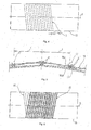
- figures 4 and 5
- show the operation of coiling the barbed metal wire in the case of a plastic plate structure to be constructed as a cylindrical shell, in side view;
- figure 6
- shows the operation of fastening the coiled metal wire with roving fibreglass tape;
- figure 7
- shows the process of producing the shell, in perspective view.
-
Figure 1 shows a prefabricated reinforced concrete pipe 1 with a large diameter, for example a diameter of 800 mm, with asteel coupler 3 at one end, which reinforced concrete pipe 1 is standing with its front side, that is its side opposite the end with acoupler 3, on a production plane, on a ring-shaped seal 2 for example made of rubber. The prefabricated reinforced concrete pipe 1 may be made for example using the ROCLA-technology, and its internal D 1 diameter is a few centimetres, for example 6-3 cm-s larger than the planned nominal diameter. The reinforced concrete pipe 1 with a primed internal surface containsinjection pipes 4 situated in one plane, entering the pipe 1 from the outside near its lower - supporting - end, whichinjection pipes 4 have cut-offcocks 4a. Practically at least two injection pipes should be used situated opposite each other, but it is even more favourable to use four-six regularly spacedinjection pipes 4. - According to the invention the internal surface of the prefabricated reinforced concrete pipe 1 is coated with a plastic layer by creating a pipe-shaped
internal shell 5 made of fibreglass polyester, containing barbs 8 embedded in its material protruding outwards, with a steel wire, inside the reinforced concrete pipe 1 in the following way: - the shell 5 - the wall of which may be 4-2 mm thick, and the construction of which is described in detail below - is entered into the reinforced concrete pipe 1 in a vertical position from above and downwards (
figure 1 , arrows), which is possible, because the external D 2 diameter of the shell 5 - measured between the external end of the protruding barbs and the internal shell surface - is the same as the nominal diameter of the finished product, so D 1 > D 2. Infigure 2 the width of the createdgap 7 is indicated with reference letter k. Then the shell 5 (in a way already known in itself, not shown in the figures) is stiffened from inside, and it is fixed in its position taken inside the reinforced concrete pipe 1 with the help of a ring-shapedupper clamp 6 and clamping elements 6a shown infigure 2 . According to the above agap 7 of a width of 1-2 cm is created between the external surface of theshell 5 and the internal surface of the reinforced concrete pipe 1, and the steel barbs 8 mentioned above protruding from theshell 5 extend into thisgap 7. In the following step thegap 7 is filled with cemented grouting mortar or cement grout - the composition of which should be determined to prevent shrinkage of the injected material - injected as shown by arrows b. In the course of the injection process obviously performed under overpressure theseal 2 prevents the mortar from leaving at the bottom, and the mortar is moved from the bottom to the top to overcome the risk of the creation of air pockets and discontinuities. - The barbs 8 of the wire embedded into the fibreglass polyester material of the shell 5 - practically the
shell 5 contains at least several hundreds of barbs 8 per square centimetre, which means that the same number of mechanic supporting points are created between theshell 5 and the mortar layer - set perfectly into the hardened cemented injected mortar, and the mortar layer itself binds to the primed internal surface of the reinforced concrete pipe 1 possibly sprayed with quartz sand - entering the gaps between the sand grains - with a cement-cement connection. In order to make this bond more intensive the external surface of theshell 5 may also be roughened by spreading quartz sand on it, and in this way the material of the mortar sets in it too. - After the injected mortar hardens at least partly, the internal strutting of the
clamp 6 and the shell can be removed, the holes of the injectingpipes 4 can be sealed and the reinforced concrete pipe 1 the internal surface of which has now been coated with a plastic layer can be taken off theseal 2 and put in use. - The equipment shown in
figure 3 and the technology illustrated with it is different from the equipment and technology shown infigures 1 and 2 in respect of that instead of injecting afterhardening material composite action between theplastic shell 5 and the reinforced concrete pipe is realised by connecting the previouslyprepared shell 5 to the not yet set material of the reinforced concrete pipe itself, and in this way the barbs 8 of the metal wire are embedded into the fresh concrete, and after the concrete sets perfect composite action is created between theshell 5 and the finished reinforced concrete pipe. Infigure 3 the external mould unit of the mould 9 of the reinforced concrete pipe to be made is marked withreference number 9a, and the internal mould unit (mould skirt) is marked withreference number 9b. At the bottom the mould 9 is positioned vertically with acentre ring 13. Before the concrete is filled into the mould space 14 reinforcement marked withreference number 10 as a whole is placed in it together with the pipe-shapedshell 5 pulled onto theinternal mould unit 9b, which shell 5 may be the same as the one sown in and described in connection withfigures 1 and 2 , so it is made of fibreglass polyester into a which a steel wire containing barbs 8 extending outside into the mould space 14 is embedded. Inside the pipe-shaped mould 9 there is a stiffening structure 11 known in itself, which, with the help oftension bolts 12, exerts an adjustable supporting force onto the internal surface of the mould 9, while on the external side theexternal mould unit 9a is supported by stiffening rings 15. - With the help of the equipment shown in
figure 3 pipes with a plastic layer on their internal surface are manufactured according to the following: - the mould 9 with vertical geometrical central axis x is assembled and connected to
centre ring 13 placed on the production plane t, thefibreglass polyester shell 5 with a slightly larger internal diameter than the external diameter of theinternal mould unit 9b is pulled onto theinternal mould unit 9b from above, then thereinforcement 10 of the reinforced concrete pipe to be manufactured is placed inside the mould space 14. After fitting the stiffening structure 11 withtension bolts 12 the mould space 14 is filled with monolithic concrete as shown by arrows c, the concrete is compacted by vibration and hardened by steaming. According to this technology theplastic shell 5 and the reinforced concrete pipe are built together in the same phase as the manufacturing of the pipe, and the barbs embedded in the set concrete material ensure perfect composite action between the reinforced concrete pipe and the internal plastic layer. - Below the manufacturing procedure of a fibreglass polyester artificial resin shell according to the invention functioning as an internal plastic layer of reinforced concrete pipes as above is described as an example, with reference to
figures 4-7 . - For the manufacturing of the shell a steel pipe - tool - is used of a maximum favourable length of 6.5 m, with an external diameter suiting the internal diameter of the reinforced concrete pipe to be manufactured, which is generally 300-3000 mm, and 35 µ, 100 mm wide seal polyester foil is wrapped around the external surface of the steel pipe.
- This seal foil surface is coated evenly with a 50 µ thick layer of flexible abrasion-proof polyester resin. In the finished product this layer forms the internal surface of the pipeline made from such reinforced concrete pipe in direct contact with the medium forwarded inside the pipes, such as sewage.
- Two layers of 100 mm wide 29.4 g/m2, 0,3 mm thick glass fibre fleece (ERC) is applied onto the polyester resin layer, and then on these two layers 24 g/m2, 0.09 mm thick layer of synthetic polyester fleece is wound; all three layers are impregnated with polyester resin and the air is discharged from them using a knurled roller.
- In the following step the whole surface is evenly coated with a layer of dried and assorted quartz sand of a grain-size of 0.8-1.2 mm and 19 µ cut fibreglass.
- The internal layer made from part-layers as described above is cured by infrared heat-curing and a thermosetting activator and peroxide system. This internal layer ensures resistance to 150-bar pressure, was, abrasion and chemicals. The external surface of the internal layer - which, for example in the case of pipelines is in direct contact with the liquid flowing inside it - is perfectly smooth, which ensures excellent hydraulic characteristics for the pipeline, and it is also highly resistant to deposits.
- After the internal layer is cured, 1,200 tex E glass fibre roving is coiled on it in precisely controlled and tense condition, by radial coiling (about 89°), impregnated with polyester resin. At the same time as radial coiling performed to an extent providing 50% coverage 10-50 mm long cut 19 µ fibreglass and dried and assorted quartz sand of a diameter of 0.8 - 1.2 mm is also spread on the surface. On this layer made by coiling roving fibre - in a number needed for the calculated and dimensioned wall width - further layers (generally one-three layers) are applied.
- In the following step the untreated barbed steel wire - with a black surface - of a diameter of 0.3 - 1.5 mm, favourably 0.6-0.8 mm us coiled onto the complete cylindrical surface along a spiral track - with funnel-type guidance -, with a 100 mm pitch. This operation is shown in
figure 4 , where the pipe-shaped plastic shell with longitudinal geometrical axis y made as above is marked withreference number 15, the barbed steel wire is marked withreference number 16, and the pitch is indicated with reference letter m. -
Figure 5 shows a section of theplastic shell 15 and thesteel wire 16 coiled on it as infigure 4 on an expanded scale, where thesteel wire 16 consists of two intertwinedsteel wire sections 16a,' 16b, on each of which two short pieces of steel wire containing barbs 8 are coiled at a givenplace 17 each, in a way that their ends protruding in different directions - partly inwards and partly outwards - form the barbs 8. The practically same distance between theplaces 17 is determined to ensure a sufficient number and density of barbs protruding from theshell 15 to provide appropriate composite action between theshell 15 and the reinforced concrete pipe to be manufactured. For example one hundred of evenly scattered barbs may protrude from the shell surface per m2. - After the
barbed steel wire 16 has been coiled as shown infigures 4 and 5 , on a spiral track going in the opposite direction with respect to the coiling direction, but with the same pitch 100 mm wide strand fastening thesteel wire 16 impregnated with thermosetting artificial resin, practically roving tape impregnated with such artificial resin, is coiled on the surface, and the complete surface is covered by such radial coiling - which ensures perfect fixation of the steel wire -, except for the barbs 8 protruding outwards, which form the points ensuring connection with the concrete. This step of the procedure is shown infigure 6 . - Finally, in the last step one layer of dried and assorted quartz sand with a diameter of 0.8-1.2 mm is spread on the external surface, as a result of which additional bond - apart from the connection ensured by the barbs 8 - is realised between the concrete and the shell, which may increase the efficiency and safety of composite action. It is pointed out here that the process of the steps described above can be followed in
figure 7 , where the same reference numbers are used as before, and the pipe-shaped plate element formed by the layers below thesteel wire 16 is marked withreference number 19 as a whole. - By choosing the density of the barbs of the steel wire and the extent of the pitch the number of the connection points - that is barbs - joining the concrete or the injected cemented mortar layer can be determined, that is the bond between the plastic layer and the concrete unit can be dimensioned.
- The advantage of the invention is that beside preserving the positive characteristics of concrete and reinforced concrete - filling the static function perfectly - a plastic layer can be formed on the surface of the concrete or reinforced concrete unit in a simple and economical way, with an optimal degree of resistance to water and abrasion, forming an absolutely stable bond to concrete materials; there are no problems deriving from the different heat-expansion coefficients of the two materials, and the lifetime of the finished product representing an extremely high usage value is extremely long.
Claims (13)
- Plastic plate structure for manufacturing a concrete or reinforced concrete pipe unit with a plastic surface layer, the plate structure preferably comprising a cross-linked, thermosetting material and reinforcing fibres, characterised by that the plastic plate structure comprises a pipe-shaped shell (15) and at least one barbed metal wire (16) comprising a plurality of barbs (8) is coiled onto the pipe-shaped shell (15), such that the barbs (8) protrude from one surface of the plate structure.
- The plastic plate structure according to claim 1, characterised by that it is made of fibreglass polyester resin.
- The plastic plate structure according to claims 1 or 2, characterised by that it is made from a combination of polyester, vinylester, epoxy, furan, bakelite, melamine or water-based polyurethane resin and/or basalt fibre and/or carbon fibre and/or aramid fibre and/or kevlar fibre.
- The plastic plate structure according to any of claims 1 to 3, characterised by that the barbed metal wire (16) is barbed steel wire (16) with an untreated surface, with a diameter of 0,3-1,5 mm, preferably between 0.6-0.8 mm.
- The plastic plate structure according to any of claims 1 to 4, characterised by that it contains a layer (or layers) of 20-50 g/m2 glass fibre fleece and 20-50 g/m2 synthetic fleece.
- The plastic plate structure according to any of claims 1 to 5, characterised by that the plastic plate structure contains a layer (or layers) of dried and assorted quartz sand with a diameter of 0.8-1.2 mm.
- The plastic plate structure according to any of claims 1 to 6, characterised by that the thickness of the external smooth layer of the plastic plate structure is between 20-80 µ, preferably about 40-50 µ.
- The plastic plate structure according to any of claims 1 to 7, characterised by that the pipe-shaped shell has an internal layer comprising:- an inner pipe-shaped layer of thermosetting artificial resin, preferably polyester resin, preferably wrapped in seal foil;- around the inner pipe-shaped layer one or more layers of glass fibre fleece and/or synthetic fleece impregnated with artificial resin, especially polyester resin; and- around the impregnated layer a sprayed layer of sand and/or cut fibres, preferably a layer of quartz sand and/or fibreglass; and- further having an external layer comprising several layers of pre-stressed roving fibre, especially glass fibre impregnated with artificial resin, applied to the internal layer by radial spiral coiling and optionally being sprayed with sand, preferably quartz sand, and/or cut fibres, preferably glass fibres; andthe barbed (8) metal wire is coiled spirally around the external layer; and the plastic plate structure has a linear clamping unit, preferably fibreglass roving impregnated with thermosetting artificial resin, coiled on the outer surface in a direction opposite to the direction of coiling of the barbed wire (16), preferably with the same pitch.
- Use of a plastic plate structure according to any of claims 1 to 8 for manufacturing a concrete or reinforced concrete unit with a plastic surface layer, the unit comprising a concrete body, optionally of reinforced concrete and the concrete body is in the form of a pipe having an internal surface, wherein the plastic plate structure is arranged such that the protruding barbs (8) extend into the internal surface of the concrete body or into an intermediate cemented layer bound to the internal surface of the concrete body.
- Use of the plastic plate structure according to claim 9, wherein the barbs (8) of the barbed wire (16) protrude into an intermediate cemented layer, the use comprising the steps of:(a) fitting the plastic plate structure into the concrete or reinforced concrete pipe unit at a given distance from the surface of the hardened concrete body to be provided with a plastic surface layer such, that a gap is formed between the concrete body and the plastic plate structure, and the protruding barbs extend into the gap, and(b) subsequently creating the intermediate cemented layer by filling the gap with cemented afterhardening material.
- Use of the plastic plate structure according to claim 10, wherein the concrete body is in the form of a prefabricated concrete pipe (1) comprising a wall having an internal surface and having one or more openings in the proximity of its lower end, and placing the concrete body with its lower end on a favourably ring-shaped seal (2) situated on a horizontal production plane; and
in step (a) the plastic plate structure is fitted at a given distance (k) from the internal surface of the concrete body; and
in step (b) the gap (7) is filled with cemented afterhardening material through one or more injection pipes (4) entering the opening(s). - Use of the plastic plate structure according to claim 9, wherein the barbs (8) of the barbed wire (16) protrude into the concrete body, the use comprising the steps of:(a) fixing the plastic plate structure to the internal side of a shuttering such, that the protruding barbs (8) extend into a space opposite said internal side,(b) filling the space with concrete, and(c) removing the shuttering after the concrete has set.
- Use of the plastic plate structure according to claim 12, wherein a mould (9) having an external mould unit (9a) and an internal mould unit (9b) and a mould space (14) between the two, is set up on a production plane (t), preferably stabilised with a centre ring (13) and a stiffening structure (11), the shuttering being formed by the internal mould unit (9b);
step (a) is performed by pulling the plastic plate structure, which is in the form of a pipe-shaped shell (5), on the internal mould-member (9b) such that the protruding barbs (8) extend into the mould space (14), and optionally reinforcement (10) is placed in the mould space (14); and
step (b) is performed by filling the mould space (14) from the top with monolithic concrete.
Applications Claiming Priority (2)
| Application Number | Priority Date | Filing Date | Title |
|---|---|---|---|
| HU0501117A HU227215B1 (en) | 2005-11-25 | 2005-11-25 | A concrete or reinforced concrete body with a plastic layer on its surface, in particular a pipe or container; a method for producing such bodies |
| PCT/HU2006/000045 WO2007060489A1 (en) | 2005-11-25 | 2006-05-23 | Concrete unit provided with a plastic surface layer; procedure and plate structure for manufacturing such units; and procedure for manufacturing such plate structure |
Publications (2)
| Publication Number | Publication Date |
|---|---|
| EP1954459A1 EP1954459A1 (en) | 2008-08-13 |
| EP1954459B1 true EP1954459B1 (en) | 2015-12-02 |
Family
ID=89986421
Family Applications (1)
| Application Number | Title | Priority Date | Filing Date |
|---|---|---|---|
| EP06744399.4A Expired - Lifetime EP1954459B1 (en) | 2005-11-25 | 2006-05-23 | Plastic plate structure for manufacturing concrete units and its use |
Country Status (3)
| Country | Link |
|---|---|
| EP (1) | EP1954459B1 (en) |
| HU (1) | HU227215B1 (en) |
| WO (1) | WO2007060489A1 (en) |
Family Cites Families (3)
| Publication number | Priority date | Publication date | Assignee | Title |
|---|---|---|---|---|
| GB1125602A (en) * | 1964-06-04 | 1968-08-28 | Vulcan Plastics Ltd | Improvements in or relating to a method of bonding materials |
| GB1145936A (en) * | 1967-06-28 | 1969-03-19 | Pipe Linings Inc | Pipeline lining and reinforcement machine |
| US6426029B1 (en) * | 1995-10-10 | 2002-07-30 | Donald R. Hiscock | Lamination between plastic resins and cement |
-
2005
- 2005-11-25 HU HU0501117A patent/HU227215B1/en not_active IP Right Cessation
-
2006
- 2006-05-23 EP EP06744399.4A patent/EP1954459B1/en not_active Expired - Lifetime
- 2006-05-23 WO PCT/HU2006/000045 patent/WO2007060489A1/en not_active Ceased
Also Published As
| Publication number | Publication date |
|---|---|
| WO2007060489A1 (en) | 2007-05-31 |
| HU227215B1 (en) | 2010-11-29 |
| EP1954459A1 (en) | 2008-08-13 |
| HU0501117D0 (en) | 2006-01-30 |
| HUP0501117A2 (en) | 2007-12-28 |
Similar Documents
| Publication | Publication Date | Title |
|---|---|---|
| US3177902A (en) | Reinforced pipe and method of making | |
| US5271193A (en) | Concrete products and methods of fabrication | |
| US3489626A (en) | Method of making a prestressed,reinforced,resin-crete concrete pipe | |
| US6360780B1 (en) | Liner for reinforcing a pipe and method of making the same | |
| US6615875B2 (en) | Liner for reinforcing a pipe and method of making the same | |
| US3532132A (en) | Apparatus for the manufacture of reinforced composite concrete pipe-lines | |
| US7370676B2 (en) | Sleeve with insert for repairing high-pressure fluid pipes | |
| EP1094171B1 (en) | Structural reinforcement member and method of utilizing the same to reinforce a product | |
| US20090314409A1 (en) | Apparatus and Method of Reinforcing a Conduit or Vessel | |
| US20120009018A1 (en) | Culvert liner | |
| CN102865419A (en) | Rehabilitation pipe and pipe rehabilitation method employing rehabilitation pipe | |
| CA1315944C (en) | Seismic anchor | |
| CN204780988U (en) | Anticorrosive aerogenerator foundation structure | |
| JP2009085004A (en) | Repair method of existing pipelines, repair materials used therefor, and pipelines | |
| CN105909885A (en) | Prestressed cylinder concrete and plastic composite pipe and construction method thereof | |
| US20120199276A1 (en) | Tubular Liner for Underground Pipes and Method of Installing Tubular Liner | |
| CN107542493A (en) | A kind of tunnel drainage system construction method of steel FRP compound bellows | |
| EP1954459A1 (en) | Concrete unit provided with a plastic surface layer; procedure and plate structure for manufacturing such units; and procedure for manufacturing such plate structure | |
| KR101155654B1 (en) | Plastic manhole with fiberglass reinforced plastic support units | |
| JP2008521650A (en) | Plastic hollow body, especially plastic pipe | |
| US20240077165A1 (en) | Lightweight strong pipe for new construction and repair of pipes | |
| RU195913U1 (en) | WELL RING | |
| JP2008088715A (en) | Concrete structure reconstructing method, concrete structure producing method, and corrosion resistant member for use in the methods | |
| Ainsworth | Fibre-reinforced plastic pipes and applications | |
| CN111561618A (en) | Plastic FRP rib composite pipe |
Legal Events
| Date | Code | Title | Description |
|---|---|---|---|
| PUAI | Public reference made under article 153(3) epc to a published international application that has entered the european phase |
Free format text: ORIGINAL CODE: 0009012 |
|
| 17P | Request for examination filed |
Effective date: 20080621 |
|
| AK | Designated contracting states |
Kind code of ref document: A1 Designated state(s): AT BE BG CH CY CZ DE DK EE ES FI FR GB GR HU IE IS IT LI LT LU LV MC NL PL PT RO SE SI SK TR |
|
| AX | Request for extension of the european patent |
Extension state: BA HR MK |
|
| R17P | Request for examination filed (corrected) |
Effective date: 20080617 |
|
| RAX | Requested extension states of the european patent have changed |
Extension state: BA Payment date: 20080617 Extension state: HR Payment date: 20080617 Extension state: MK Payment date: 20080617 |
|
| RBV | Designated contracting states (corrected) |
Designated state(s): AT BE BG CH CY CZ DE DK EE ES FI FR GB GR HU IE IS IT LI LT LU LV MC NL PL PT RO SE SI SK TR |
|
| RAX | Requested extension states of the european patent have changed |
Extension state: BA Payment date: 20080617 Extension state: HR Payment date: 20080617 Extension state: MK Payment date: 20080617 |
|
| 17Q | First examination report despatched |
Effective date: 20120724 |
|
| GRAP | Despatch of communication of intention to grant a patent |
Free format text: ORIGINAL CODE: EPIDOSNIGR1 |
|
| INTG | Intention to grant announced |
Effective date: 20150611 |
|
| GRAS | Grant fee paid |
Free format text: ORIGINAL CODE: EPIDOSNIGR3 |
|
| GRAA | (expected) grant |
Free format text: ORIGINAL CODE: 0009210 |
|
| AK | Designated contracting states |
Kind code of ref document: B1 Designated state(s): AT BE BG CH CY CZ DE DK EE ES FI FR GB GR HU IE IS IT LI LT LU LV MC NL PL PT RO SE SI SK TR |
|
| AX | Request for extension of the european patent |
Extension state: BA HR MK |
|
| REG | Reference to a national code |
Ref country code: GB Ref legal event code: FG4D |
|
| REG | Reference to a national code |
Ref country code: AT Ref legal event code: REF Ref document number: 763419 Country of ref document: AT Kind code of ref document: T Effective date: 20151215 Ref country code: CH Ref legal event code: EP |
|
| REG | Reference to a national code |
Ref country code: IE Ref legal event code: FG4D |
|
| REG | Reference to a national code |
Ref country code: DE Ref legal event code: R096 Ref document number: 602006047415 Country of ref document: DE |
|
| REG | Reference to a national code |
Ref country code: NL Ref legal event code: MP Effective date: 20160302 |
|
| REG | Reference to a national code |
Ref country code: LT Ref legal event code: MG4D |
|
| REG | Reference to a national code |
Ref country code: AT Ref legal event code: MK05 Ref document number: 763419 Country of ref document: AT Kind code of ref document: T Effective date: 20151202 |
|
| PG25 | Lapsed in a contracting state [announced via postgrant information from national office to epo] |
Ref country code: ES Free format text: LAPSE BECAUSE OF FAILURE TO SUBMIT A TRANSLATION OF THE DESCRIPTION OR TO PAY THE FEE WITHIN THE PRESCRIBED TIME-LIMIT Effective date: 20151202 Ref country code: LT Free format text: LAPSE BECAUSE OF FAILURE TO SUBMIT A TRANSLATION OF THE DESCRIPTION OR TO PAY THE FEE WITHIN THE PRESCRIBED TIME-LIMIT Effective date: 20151202 |
|
| PG25 | Lapsed in a contracting state [announced via postgrant information from national office to epo] |
Ref country code: GR Free format text: LAPSE BECAUSE OF FAILURE TO SUBMIT A TRANSLATION OF THE DESCRIPTION OR TO PAY THE FEE WITHIN THE PRESCRIBED TIME-LIMIT Effective date: 20160303 Ref country code: NL Free format text: LAPSE BECAUSE OF FAILURE TO SUBMIT A TRANSLATION OF THE DESCRIPTION OR TO PAY THE FEE WITHIN THE PRESCRIBED TIME-LIMIT Effective date: 20151202 Ref country code: SE Free format text: LAPSE BECAUSE OF FAILURE TO SUBMIT A TRANSLATION OF THE DESCRIPTION OR TO PAY THE FEE WITHIN THE PRESCRIBED TIME-LIMIT Effective date: 20151202 Ref country code: PL Free format text: LAPSE BECAUSE OF FAILURE TO SUBMIT A TRANSLATION OF THE DESCRIPTION OR TO PAY THE FEE WITHIN THE PRESCRIBED TIME-LIMIT Effective date: 20151202 Ref country code: LV Free format text: LAPSE BECAUSE OF FAILURE TO SUBMIT A TRANSLATION OF THE DESCRIPTION OR TO PAY THE FEE WITHIN THE PRESCRIBED TIME-LIMIT Effective date: 20151202 Ref country code: AT Free format text: LAPSE BECAUSE OF FAILURE TO SUBMIT A TRANSLATION OF THE DESCRIPTION OR TO PAY THE FEE WITHIN THE PRESCRIBED TIME-LIMIT Effective date: 20151202 Ref country code: FI Free format text: LAPSE BECAUSE OF FAILURE TO SUBMIT A TRANSLATION OF THE DESCRIPTION OR TO PAY THE FEE WITHIN THE PRESCRIBED TIME-LIMIT Effective date: 20151202 |
|
| PG25 | Lapsed in a contracting state [announced via postgrant information from national office to epo] |
Ref country code: IS Free format text: LAPSE BECAUSE OF FAILURE TO SUBMIT A TRANSLATION OF THE DESCRIPTION OR TO PAY THE FEE WITHIN THE PRESCRIBED TIME-LIMIT Effective date: 20151202 |
|
| PG25 | Lapsed in a contracting state [announced via postgrant information from national office to epo] |
Ref country code: CZ Free format text: LAPSE BECAUSE OF FAILURE TO SUBMIT A TRANSLATION OF THE DESCRIPTION OR TO PAY THE FEE WITHIN THE PRESCRIBED TIME-LIMIT Effective date: 20151202 Ref country code: IT Free format text: LAPSE BECAUSE OF FAILURE TO SUBMIT A TRANSLATION OF THE DESCRIPTION OR TO PAY THE FEE WITHIN THE PRESCRIBED TIME-LIMIT Effective date: 20151202 |
|
| PG25 | Lapsed in a contracting state [announced via postgrant information from national office to epo] |
Ref country code: PT Free format text: LAPSE BECAUSE OF FAILURE TO SUBMIT A TRANSLATION OF THE DESCRIPTION OR TO PAY THE FEE WITHIN THE PRESCRIBED TIME-LIMIT Effective date: 20160404 Ref country code: EE Free format text: LAPSE BECAUSE OF FAILURE TO SUBMIT A TRANSLATION OF THE DESCRIPTION OR TO PAY THE FEE WITHIN THE PRESCRIBED TIME-LIMIT Effective date: 20151202 Ref country code: RO Free format text: LAPSE BECAUSE OF FAILURE TO SUBMIT A TRANSLATION OF THE DESCRIPTION OR TO PAY THE FEE WITHIN THE PRESCRIBED TIME-LIMIT Effective date: 20151202 Ref country code: SK Free format text: LAPSE BECAUSE OF FAILURE TO SUBMIT A TRANSLATION OF THE DESCRIPTION OR TO PAY THE FEE WITHIN THE PRESCRIBED TIME-LIMIT Effective date: 20151202 Ref country code: IS Free format text: LAPSE BECAUSE OF FAILURE TO SUBMIT A TRANSLATION OF THE DESCRIPTION OR TO PAY THE FEE WITHIN THE PRESCRIBED TIME-LIMIT Effective date: 20160402 Ref country code: BE Free format text: LAPSE BECAUSE OF NON-PAYMENT OF DUE FEES Effective date: 20160531 |
|
| REG | Reference to a national code |
Ref country code: DE Ref legal event code: R097 Ref document number: 602006047415 Country of ref document: DE |
|
| PLBE | No opposition filed within time limit |
Free format text: ORIGINAL CODE: 0009261 |
|
| STAA | Information on the status of an ep patent application or granted ep patent |
Free format text: STATUS: NO OPPOSITION FILED WITHIN TIME LIMIT |
|
| PG25 | Lapsed in a contracting state [announced via postgrant information from national office to epo] |
Ref country code: DK Free format text: LAPSE BECAUSE OF FAILURE TO SUBMIT A TRANSLATION OF THE DESCRIPTION OR TO PAY THE FEE WITHIN THE PRESCRIBED TIME-LIMIT Effective date: 20151202 |
|
| 26N | No opposition filed |
Effective date: 20160905 |
|
| PG25 | Lapsed in a contracting state [announced via postgrant information from national office to epo] |
Ref country code: SI Free format text: LAPSE BECAUSE OF FAILURE TO SUBMIT A TRANSLATION OF THE DESCRIPTION OR TO PAY THE FEE WITHIN THE PRESCRIBED TIME-LIMIT Effective date: 20151202 |
|
| REG | Reference to a national code |
Ref country code: DE Ref legal event code: R119 Ref document number: 602006047415 Country of ref document: DE |
|
| PG25 | Lapsed in a contracting state [announced via postgrant information from national office to epo] |
Ref country code: BE Free format text: LAPSE BECAUSE OF FAILURE TO SUBMIT A TRANSLATION OF THE DESCRIPTION OR TO PAY THE FEE WITHIN THE PRESCRIBED TIME-LIMIT Effective date: 20151202 Ref country code: LU Free format text: LAPSE BECAUSE OF FAILURE TO SUBMIT A TRANSLATION OF THE DESCRIPTION OR TO PAY THE FEE WITHIN THE PRESCRIBED TIME-LIMIT Effective date: 20160523 |
|
| REG | Reference to a national code |
Ref country code: CH Ref legal event code: PL |
|
| GBPC | Gb: european patent ceased through non-payment of renewal fee |
Effective date: 20160523 |
|
| PG25 | Lapsed in a contracting state [announced via postgrant information from national office to epo] |
Ref country code: LI Free format text: LAPSE BECAUSE OF NON-PAYMENT OF DUE FEES Effective date: 20160531 Ref country code: CH Free format text: LAPSE BECAUSE OF NON-PAYMENT OF DUE FEES Effective date: 20160531 |
|
| REG | Reference to a national code |
Ref country code: IE Ref legal event code: MM4A |
|
| REG | Reference to a national code |
Ref country code: FR Ref legal event code: ST Effective date: 20170131 |
|
| PG25 | Lapsed in a contracting state [announced via postgrant information from national office to epo] |
Ref country code: DE Free format text: LAPSE BECAUSE OF NON-PAYMENT OF DUE FEES Effective date: 20161201 Ref country code: FR Free format text: LAPSE BECAUSE OF NON-PAYMENT OF DUE FEES Effective date: 20160531 |
|
| PG25 | Lapsed in a contracting state [announced via postgrant information from national office to epo] |
Ref country code: IE Free format text: LAPSE BECAUSE OF NON-PAYMENT OF DUE FEES Effective date: 20160523 Ref country code: GB Free format text: LAPSE BECAUSE OF NON-PAYMENT OF DUE FEES Effective date: 20160523 |
|
| PG25 | Lapsed in a contracting state [announced via postgrant information from national office to epo] |
Ref country code: CY Free format text: LAPSE BECAUSE OF FAILURE TO SUBMIT A TRANSLATION OF THE DESCRIPTION OR TO PAY THE FEE WITHIN THE PRESCRIBED TIME-LIMIT Effective date: 20151202 Ref country code: HU Free format text: LAPSE BECAUSE OF FAILURE TO SUBMIT A TRANSLATION OF THE DESCRIPTION OR TO PAY THE FEE WITHIN THE PRESCRIBED TIME-LIMIT; INVALID AB INITIO Effective date: 20060523 |
|
| PG25 | Lapsed in a contracting state [announced via postgrant information from national office to epo] |
Ref country code: MC Free format text: LAPSE BECAUSE OF FAILURE TO SUBMIT A TRANSLATION OF THE DESCRIPTION OR TO PAY THE FEE WITHIN THE PRESCRIBED TIME-LIMIT Effective date: 20151202 Ref country code: TR Free format text: LAPSE BECAUSE OF FAILURE TO SUBMIT A TRANSLATION OF THE DESCRIPTION OR TO PAY THE FEE WITHIN THE PRESCRIBED TIME-LIMIT Effective date: 20151202 |
|
| PG25 | Lapsed in a contracting state [announced via postgrant information from national office to epo] |
Ref country code: BG Free format text: LAPSE BECAUSE OF FAILURE TO SUBMIT A TRANSLATION OF THE DESCRIPTION OR TO PAY THE FEE WITHIN THE PRESCRIBED TIME-LIMIT Effective date: 20151202 |