EP1954091B1 - Efficient network hand-off utilizing stored beam-forming information - Google Patents
Efficient network hand-off utilizing stored beam-forming information Download PDFInfo
- Publication number
- EP1954091B1 EP1954091B1 EP08001746A EP08001746A EP1954091B1 EP 1954091 B1 EP1954091 B1 EP 1954091B1 EP 08001746 A EP08001746 A EP 08001746A EP 08001746 A EP08001746 A EP 08001746A EP 1954091 B1 EP1954091 B1 EP 1954091B1
- Authority
- EP
- European Patent Office
- Prior art keywords
- hand
- communication
- forming information
- network
- particular hand
- Prior art date
- Legal status (The legal status is an assumption and is not a legal conclusion. Google has not performed a legal analysis and makes no representation as to the accuracy of the status listed.)
- Active
Links
- 238000004891 communication Methods 0.000 claims description 272
- 238000000034 method Methods 0.000 claims description 81
- 238000010295 mobile communication Methods 0.000 description 85
- 238000010586 diagram Methods 0.000 description 20
- 230000001413 cellular effect Effects 0.000 description 16
- 230000004044 response Effects 0.000 description 14
- 101150003814 MCD1 gene Proteins 0.000 description 10
- 230000005540 biological transmission Effects 0.000 description 10
- 230000006870 function Effects 0.000 description 6
- 230000000694 effects Effects 0.000 description 5
- 238000012545 processing Methods 0.000 description 5
- 230000000977 initiatory effect Effects 0.000 description 3
- 230000003068 static effect Effects 0.000 description 3
- 230000003044 adaptive effect Effects 0.000 description 2
- 230000006399 behavior Effects 0.000 description 2
- 230000010267 cellular communication Effects 0.000 description 2
- 238000012937 correction Methods 0.000 description 2
- 230000003287 optical effect Effects 0.000 description 2
- 235000015429 Mirabilis expansa Nutrition 0.000 description 1
- 244000294411 Mirabilis expansa Species 0.000 description 1
- 238000013459 approach Methods 0.000 description 1
- 239000002131 composite material Substances 0.000 description 1
- 230000001419 dependent effect Effects 0.000 description 1
- 239000000463 material Substances 0.000 description 1
- 238000005259 measurement Methods 0.000 description 1
- 235000013536 miso Nutrition 0.000 description 1
- 238000012986 modification Methods 0.000 description 1
- 230000004048 modification Effects 0.000 description 1
- 230000008569 process Effects 0.000 description 1
- URWAJWIAIPFPJE-YFMIWBNJSA-N sisomycin Chemical compound O1C[C@@](O)(C)[C@H](NC)[C@@H](O)[C@H]1O[C@@H]1[C@@H](O)[C@H](O[C@@H]2[C@@H](CC=C(CN)O2)N)[C@@H](N)C[C@H]1N URWAJWIAIPFPJE-YFMIWBNJSA-N 0.000 description 1
- 238000012358 sourcing Methods 0.000 description 1
Images


Classifications
-
- H—ELECTRICITY
- H04—ELECTRIC COMMUNICATION TECHNIQUE
- H04B—TRANSMISSION
- H04B7/00—Radio transmission systems, i.e. using radiation field
- H04B7/02—Diversity systems; Multi-antenna system, i.e. transmission or reception using multiple antennas
- H04B7/04—Diversity systems; Multi-antenna system, i.e. transmission or reception using multiple antennas using two or more spaced independent antennas
- H04B7/0408—Diversity systems; Multi-antenna system, i.e. transmission or reception using multiple antennas using two or more spaced independent antennas using two or more beams, i.e. beam diversity
-
- H—ELECTRICITY
- H04—ELECTRIC COMMUNICATION TECHNIQUE
- H04W—WIRELESS COMMUNICATION NETWORKS
- H04W16/00—Network planning, e.g. coverage or traffic planning tools; Network deployment, e.g. resource partitioning or cells structures
- H04W16/24—Cell structures
- H04W16/28—Cell structures using beam steering
-
- H—ELECTRICITY
- H04—ELECTRIC COMMUNICATION TECHNIQUE
- H04W—WIRELESS COMMUNICATION NETWORKS
- H04W36/00—Hand-off or reselection arrangements
- H04W36/08—Reselecting an access point
- H04W36/085—Reselecting an access point involving beams of access points
-
- H—ELECTRICITY
- H04—ELECTRIC COMMUNICATION TECHNIQUE
- H04W—WIRELESS COMMUNICATION NETWORKS
- H04W36/00—Hand-off or reselection arrangements
- H04W36/24—Reselection being triggered by specific parameters
- H04W36/32—Reselection being triggered by specific parameters by location or mobility data, e.g. speed data
- H04W36/322—Reselection being triggered by specific parameters by location or mobility data, e.g. speed data by location data
-
- H—ELECTRICITY
- H04—ELECTRIC COMMUNICATION TECHNIQUE
- H04W—WIRELESS COMMUNICATION NETWORKS
- H04W36/00—Hand-off or reselection arrangements
- H04W36/34—Reselection control
- H04W36/38—Reselection control by fixed network equipment
Definitions
- Figure 5 is a block diagram illustrating an exemplary communication environment utilizing beam-forming for at least a portion of communications.
- the exemplary system 100 may comprise an interleaver 120 that receives the encoded data from the channel encoder 110.
- the interleaver 120 may, for example, perform interleaving to spread errors.
- the exemplary system 100 may comprise a serial-to-parallel converter 130 that divides the single data stream out of the interleaver 120 (or channel encoder 110) into a plurality of ( e.g. , up to N) parallel paths.
- the outputs of the serial-to-parallel converter 130 may be coupled to a plurality of transmitters (e.g. , transmitter 140 through transmitter 150) and respective antennas for transmission.
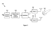
- the exemplary system 300 may comprise a beam former and/or combiner 320 (e.g. , a digital beam-former and/or combiner) that receives the encoded data from the channel encoder 310.
- the beam former/combiner 320 may, for example, form parallel signals (e.g. , N signals) that, when ultimately transmitted through corresponding transmitters and antennas, focus transmission energy in a particular direction ( e.g. , forming a directed transmission beam).
- the outputs of the beam former/combiner 320 may be modulated by a modulator 330 and communicated to a plurality of transmitters ( e.g. , transmitter 340 through transmitter 350) and respective antennas for transmission. As illustrated by the exemplary antenna gain pattern 360, the energy of the transmitted plurality of signals may constructively combine to focus composite transmission energy in a particular direction.
- the energy of a received plurality of signals may be constructively combined to focus reception energy from a particular direction (e.g. , forming a directed reception beam).
- the transmitters 340-350 may be replaced by receivers and/or transceivers, the module 340 may be replaced with a demodulator, and the channel encoder 310 may be replaced with a decoder.
- the mobile communication device 405 is illustrated in Figure 4 with multiple ( e.g. , three) concurrent or serialized links to multiple respective communication networks.
- the mobile communication device 405 may be capable of communicating with a Cellular Network 430 via an RF link, a WMAN 420 via an RF link, and a WLAN 410 via an RF link.
- Such links may, for example and without limitation, be maintained utilizing a plurality of communication stacks in the MCD 405.
- the mobile communication device 405 may utilize communication links through any of a variety of communication media.
- the mobile communication device 405 may communicate utilizing wireless RF, non-tethered optical, tethered optical or wired links.
- Figure 4 shows a block diagram illustrating an exemplary communication environment 400 for a mobile communication device 405. Various portions of Figure 4 may be referred to directly or by inference in the following discussion. Note that the exemplary communication environment 400 is merely an exemplary illustration. Thus, various features of the exemplary communication environment 400 should not be utilized to limit the scope of various aspects of the present invention unless explicitly claimed.
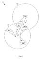
- Figure 5 is a block diagram illustrating an exemplary communication environment 500 utilizing beam-forming for at least a portion of communications.
- a first access point AP1 is communicating in a first coverage zone 510 (or area)
- a second access point AP2 is communicating in a second coverage zone 550.
- the first access point AP1 and the second access point AP2 may, for example and without limitation, be associated with different communication networks and/or different types of communication networks (e.g. , telecommunication network, computer network, satellite communication network, terrestrial communication network, WLAN, WPAN, WMAN, WWAN, etc.).
- a mobile communication device MCD1 may be handed off from a first access point AP1 that uses an omni-directional antenna pattern to communicate with the mobile communication device MCD1 to a second access point AP2 that uses beam-forming to communicate with the mobile communication device MCD2.
- a mobile communication device MCD1 may be handed off from a first access point AP1 that uses a static directional antenna pattern (e.g. , a pie-shaped sector pattern) to communicate with the mobile communication device MCD1 to a second access point AP2 that uses beam-forming to communicate with the mobile communication device MCD1 initially and then switches to an omni-directional antenna pattern and/or MIMO communication as the mobile communication device moves away from the fringes of the coverage area.
- a static directional antenna pattern e.g. , a pie-shaped sector pattern
- the exemplary method 600 may, at step 610, comprise storing beam-forming information associated with a particular hand-off.
- Such storing may, for example, occur prior to a determination being made to perform the particular hand-off. For example, such storing may occur prior to a determination being made that the particular hand-off is imminent, going to occur relatively soon ( e.g ., during a present communication, during a particular time window, etc.), or going to occur in the relatively distant future.
- Such storing may also, for example, occur prior to a determination being made that the particular hand-off is probably going to occur or probably going to occur to a particular degree or threshold limit.
- Step 610 may, for example, comprise storing the beam-forming information associated with a particular hand-off in apparatus of a communication network (e.g. , at an access point, network controller, network database, etc.).
- step 610 may comprise storing such beam-forming information for particularly common hand-off scenarios experienced by the access point (e . g ., hand-offs with particular network access points, hotspots, mobile communication devices, etc.).
- step 610 may comprise storing the beam-forming information at a central repository accessible by a plurality of different communication networks.
- step 610 may comprise storing the beam-forming information at the mobile communication device.
- the stored beam-forming information may, for example, comprise any of a variety of characteristics associated with forming a directed communication beam.
- the stored beam-forming information may comprise respective timing and/or phase information associated with a plurality of antennas and/or associated transmitters and/or receivers.
- the stored beam-forming information may comprise beam direction information.
- the stored beam-forming information may comprise information associated with latency, time, transmit power, antenna element identification, transmitter and/or receiver identification, etc. Accordingly, the scope of various aspects of the present invention should not be limited by characteristics of particular beam-forming information unless explicitly claimed.
- the beam-forming information may comprise information that may be utilized to direct a communication beam to the particular location.
- Step 630 may comprise accessing the stored beam-forming information in any of a variety of manners.
- step 630 may comprise accessing the stored beam-forming information based, at least in part, on location information, network and/or access point identity information, communication device identity, user identity information, time and/or day information, distance and/or direction information etc.
- step 630 may comprise utilizing location information to access the stored beam-forming information.
- step 630 may comprise utilizing location information as an index (or one of a plurality of indices) to access particular stored beam-forming information.
- step 630 may comprise utilizing location information as a database search criterion to search for particular stored beam-forming information.
- step 630 may comprise utilizing location information as general search criteria for beam-forming information. Accordingly, the scope of various aspects of the present invention should not be limited by characteristics of any particular manner of utilizing location information to access beam-forming information, unless explicitly claimed.
- step 630 may comprise identifying an access point of a communication network (e.g. , by name, by address (e.g. , IP address), by arbitrary tag, etc.) associated with the particular hand-off, and accessing the stored beam-forming information based, at least in part, on information of the access point identity.
- hand-offs may be performed between access points of a same communication network and/or between access points of different respective networks.
- Access point identity may be determined in any of a variety of manners.
- step 630 may comprise determining access point identity through direction communication with the access point and/or through communication with a network controller or other apparatus of a communication network associated with the access point.
- step 630 may comprise determining access point identity through communication with a mobile communication device (e.g. , the mobile communication device to be handed off to or from the access point).
- step 630 may comprise utilizing determined location information to ascertain access point identity.
- step 630 may comprise determining access point identity based, at least in part, on transmissions from the access point (e.g. , beacons, typical data messages, control messages, synchronization signals, etc.) or other access points associated therewith. Accordingly, the scope of various aspects of the present invention should not be limited by characteristics of any particular manner of determining access point identity.
- step 630 may comprise utilizing access point identity to access the stored beam-forming information.
- step 630 may comprise utilizing access point identity information as an index (or one of a plurality of indices) to access particular stored beam-forming information.
- step 630 may comprise utilizing access point identity information as a database search criterion to search for particular stored beam-forming information.
- step 630 may comprise utilizing access point identity information as general search criteria for beam-forming information. Accordingly, the scope of various aspects of the present invention should not be limited by characteristics of any particular manner of utilizing access point identity information to access beam-forming information, unless explicitly claimed.
- the previous examples present the determination and/or utilization of location, network identity and access point identity to access stored beam-forming information. Note that such examples are non-limiting illustrations and many other manners of accessing the stored beam-forming information, some of which were presented above, are contemplated. Additionally, any combination of the various manners is contemplated. For example and without limitation, any combination of location, network identity, access point identity, mobile communication device identity, user identity, time information, day information, service type, service availability, service plan provisions, etc., may be utilized to access stored beam-forming information.
- the exemplary method 700 may, at step 710, comprise determining to perform a hand-off.
- Step 710 may, for example and without limitation, share any or all characteristics with step 620 of the exemplary method 600 illustrated in Figure 6 and discussed previously.
- the exemplary method 700 may, at step 720, comprise determining a location of (or associated with) a hand-off target (e.g ., a mobile communication device to be handed off).
- Step 720 may comprise determining the location of the hand-off target in any of a variety of manners. For example and without limitation, step 720 may share any or all characteristics with step 630 of the exemplary method 600 illustrated in Figure 6 and discussed previously.
- step 720 may comprise retrieving location information from a memory (e.g. , from a memory of the mobile communication device being handed off and/or a memory of (or accessible by) communication network). Still further for example, step 720 may comprise determining a location associated with a known network (e.g. , WLAN location, WPAN location, etc. that may be in communication with the mobile communication device before being handed off or that will be in communication with the mobile communication device after being handed off). Also for example, step 720 may comprise determining a location associated with a particular communication network access point and/or coverage area (e.g. , WMAN access point, cellular base station, etc.
- a known network e.g. , WLAN location, WPAN location, etc.
- step 720 may comprise determining a location based, at least in part, on information input from a user of a mobile communication device being handed off and/or an operator of a communication network.
- step 720 may comprise predicting (e.g. , interpolating) a location of a mobile communication device associated with a particular hand-off (e.g. , based on monitored behavior, travel patterns, hand-off patterns, etc.). Accordingly, the scope of various aspects of the present invention should not be limited by characteristics of any particular manner of determining location unless explicitly claimed.
- location information associated with the determined location may comprise characteristics of any of a variety of types of location information.
- the location information may comprise information of geographical coordinates (e.g. , based on any of a number of geographical location systems), street addresses, landmarks, building identity and/or location, business identity and/or location, entertainment venue identity, intersections, transportation hub identity, etc.
- location information may also, for example, comprise location information corresponding to network location (e.g. , hand-off source network and/or hand-off recipient network) and/or mobile communication device location. Accordingly, the scope of various aspects of the present invention should not be limited by characteristics of any particular type of location information unless explicitly claimed.
- the exemplary method 700 may, at step 730, comprise determining beam-forming parameters associated with the hand-off location (e.g. , as determined at step 720).
- Step 730 may comprise determining the beam-forming parameters in any of a variety of manners.
- step 730 may comprise accessing stored beam-forming parameters associated with the determined location. Non-limiting examples of such access were discussed previously with regard to step 630 of the exemplary method 600 illustrated in Figure 6 .
- the exemplary method 700 may, at step 740, comprise utilizing determined beam-forming parameters (e.g. , as determined at step 730) to form a communication beam (e.g. , a transmission and/or reception beam) to utilize in performing the hand-off.
- Step 740 may, for example and without limitation, share any or all characteristics with step 640 of the exemplary method 600 illustrated in Figure 6 and discussed previously.
- the exemplary method 800 may, at step 820, comprise identifying one or more communication networks (or access points) associated with the hand-off (e.g ., a communication network sourcing and/or receiving a mobile communication device hand-off).
- Step 820 may comprise determining the location of the hand-off target in any of a variety of manners. For example and without limitation, step 820 may share any or all characteristics with step 630 of the exemplary method 600 illustrated in Figure 6 and discussed previously.
- step 820 may comprise determining network identity through direct communication with the network and/or through communication with a communication network associated with the network. Also for example, step 820 may comprise determining network identity through communication with a mobile communication device ( e.g ., the mobile communication device to be handed off to or from the network). Further for example, step 820 may comprise utilizing determined location information to ascertain network identity. Also for example, step 820 may comprise determining network identity based, at least in part, on transmissions from the network (e . g ., beacons, typical data messages, control messages, synchronization signals, etc.). Accordingly, the scope of various aspects of the present invention should not be limited by characteristics of any particular manner of determining network identity.
- a mobile communication device e.g ., the mobile communication device to be handed off to or from the network.
- step 820 may comprise utilizing determined location information to ascertain network identity.
- step 820 may comprise determining network identity based, at least in part, on transmissions from the network (e . g .
- step 830 may comprise calculating the beam-forming parameters as a function of the identified communication network(s) (e.g ., as a function of a beam direction associated with the identified communication network(s)). For example, step 830 may comprise determining timing and/or phase relationships corresponding to various antennas and/or transmitters and/or receivers for directing a beam of a particular shape to the identified communication network(s). Also for example, step 830 may comprise determining beam-forming parameters as a combination of accessed stored beam-forming information and calculated adjustments to such accessed stored information. Accordingly, the scope of various aspects of the present invention should not be limited by characteristics of any particular manner of determining beam-forming parameters associated with one or more identified communication networks unless explicitly claimed.
- the exemplary method 800 may, at step 840, comprise utilizing determined beam-forming parameters (e.g ., as determined at step 830) to form a communication beam (e.g ., a transmission and/or reception beam) to utilize in performing the hand-off.
- Step 840 may, for example and without limitation, share any or all characteristics with steps 640 and 740 of the exemplary methods 600 and 700 illustrated in Figures 6-7 and discussed previously.
- FIG. 9 such figure is a diagram illustrating a non-limiting exemplary block diagram of a communication device 900 that operates to perform efficient network hand-off utilizing beam forming in accordance with various aspects of the present invention.
- the communication device 900 may, for example, be a mobile communication device, a network access point or base station, a network controller or other network infrastructure component or subsystem, an integrated circuit, an insertible communication module, etc.
- the communication device 900 may, for example, share any or all characteristics with the exemplary communication systems 100, 200 and 300 illustrated in Figures 1-3 and discussed previously. Also for example, the communication device 900 may share characteristics with the mobile communication devices 405 and MCD1 illustrated in Figures 4-5 and discussed previously.
- the exemplary communication device 900 may also comprise a variety of signal processing modules (e.g. , hardware and/or software modules) that operate to perform a variety of signal processing functions, non-limiting examples of which were provided previously in the discussion of Figures 6-8 .
- the exemplary communication device 900 may comprise a processor 960 (e.g ., a baseband processor, general microprocessor, digital signal processor, etc.) that operates to execution software or firmware instructions (e.g. , applications and/or subroutines) stored in a memory 950 (on-board the processor 960 or separate from the processor 960).
- a processor 960 may thus perform any of the functionality discussed previously.
Landscapes
- Engineering & Computer Science (AREA)
- Computer Networks & Wireless Communication (AREA)
- Signal Processing (AREA)
- Mobile Radio Communication Systems (AREA)
Description
- In a dynamic network environment, a communication system (e.g., a portable communication system) may move in and out of coverage areas associated with a plurality of different communication networks. Performing network hand-offs presents many challenges.
- Further limitations and disadvantages of conventional and traditional approaches will become apparent to one of skill in the art, through comparison of such systems with the present invention as set forth in the remainder of the present application with reference to the drawings.
-
WO 01/39524 - According to the invention, there are provided a method in a communication system for performing communication device hand-off as defined by
independent claim 1, and a processor for facilitating communication device hand-off as defined by independent claim 7. - Further advantageous features of the invention are defined by the dependent subclaims.
- Various aspects of the present invention provide a system and method for performing efficient network hand-off utilizing beam-forming information, substantially as shown in and/or described in connection with at least one of the figures, as set forth more completely in the claims.
Advantageously, the method further comprises storing beam-forming information associated with the particular hand-off before determining to perform the particular hand-off, and wherein accessing stored beam-forming information associated with the particular hand-off to be performed comprises accessing the stored beam-forming information associated with the particular hand-off after determining to perform the particular hand-off.
Advantageously, storing beam-forming information associated with the particular hand-off before determining to perform the particular hand-off comprises storing beam-forming information associated with the particular hand-off before determining that performance of the particular hand-off is imminent.
Advantageously, storing beam-forming information associated with the particular hand-off comprises storing the beam-forming information at an access point of a communication network.
Advantageously, storing beam-forming information associated with the particular hand-off comprises storing the beam-forming information in a manner that is accessible by hand-off location.
Advantageously, storing beam-forming information associated with the particular hand-off comprises storing the beam-forming information in a manner that is accessible by network identification.
Advantageously, accessing stored beam-forming information associated with the particular hand-off to be performed comprises: - determining a location associated with the particular hand-off to be performed; and
- utilizing information of the determined location to access the stored beam-forming information associated with the particular hand-off to be performed.
- identifying a communication network associated with the particular hand-off to be performed; and
- utilizing the identity of the identified communication network to access the stored beam-forming information associated with the particular hand-off to be performed.
- utilizing the formed communication beam to hand off a mobile communication device from a first communication network to a second communication network different from the first communication network;
- prior to performing the hand-off, providing a communication service to the mobile communication device with the first communication network; and
- after performing the hand-off, continuing to provide the communication service to the mobile communication device with the second communication network.
- the at least one module operates to store beam-forming information associated with the particular hand-off before determining to perform the particular hand-off; and
- the at least one module operates to access stored beam-forming information associated with the particular hand-off to be performed by, at least in part, operating to access the stored beam-forming information associated with the particular hand-off after determining to perform the particular hand-off.
- determine a location associated with the particular hand-off to be performed; and
- utilize information of the determined location to access the stored beam-forming information associated with the particular hand-off to be performed.
- identify a communication network associated with the particular hand-off to be performed; and
- utilize the identity of the identified communication network to access the stored beam-forming information associated with the particular hand-off to be performed.
- utilize the formed communication beam to hand off a mobile communication device from a first communication network to a second communication network different from the first communication network;
- prior to performing the hand-off, provide a communication service to the mobile communication device with the first communication network; and
- after performing the hand-off, continue to provide the communication service to the mobile communication device with the second communication network.
-
Figure 1 is a diagram illustrating an exemplary MIMO transmitting configuration. -
Figure 2 is a diagram illustrating an exemplary MIMO receiving configuration. -
Figure 3 is a diagram illustrating an exemplary communication system having a beam-forming configuration. -
Figure 4 is a block diagram illustrating an exemplary communication environment for a mobile communication device. -
Figure 5 is a block diagram illustrating an exemplary communication environment utilizing beam-forming for at least a portion of communications. -
Figure 6 is a flow diagram illustrating a method for efficient network hand-off, utilizing stored beam-forming information, in accordance with various aspects of the present invention. -
Figure 7 is a flow diagram illustrating a method for efficient network hand-off, associating location information with beam-forming information, in accordance with various aspects of the present invention. -
Figure 8 is a flow diagram illustrating a method for efficient network hand-off, associating network identification with beam-forming information, in accordance with various aspects of the present invention. -
Figure 9 is a diagram illustrating a non-limiting exemplary block diagram of a communication device implementing various aspects of the present invention. - The following discussion may illustrate various aspects of the present invention by referring to communication systems having Multiple-Input-Multiple-Output ("MIMO") communication capability.
Figures 1 and 2 illustrate basic MIMO transmitting and receiving configurations, respectively. Note, however, that the scope of various aspects of the present invention should not be limited by particular characteristics of MIMO systems and/or of systems with both MIMO and beam-forming capability unless explicitly claimed as such. - The following discussion will refer to various communication modules, components or circuits. Such modules, components or circuits may generally comprise hardware, software or a combination thereof. Accordingly, the scope of various aspects of the present invention should not be limited by characteristics of particular hardware and/or software implementations of a module, component or circuit unless explicitly claimed as such. For example and without limitation, various aspects of the present invention may be implemented by a processor (e.g., a microprocessor, digital signal processor, baseband processor, microcontroller, etc.) executing software instructions (e.g., stored in volatile and/or non-volatile memory). Also for example, various aspects of the present invention may be implemented by an application-specific integrated circuit ("ASIC").
- The following discussion will also refer to communication networks and various aspects thereof. For the following discussion, a communication network is generally the communication infrastructure through which a mobile communication device ("MCD") may communicate. For example and without limitation, a communication network may comprise a cellular communication network, a wireless metropolitan area network (WMAN), a wireless local area network (WLAN), a wireless personal area network (WPAN), etc. A particular communication network may, for example, generally have a corresponding communication protocol according to which a communication device (e.g., a MCD) may communicate with the communication network. Unless so claimed, the scope of various aspects of the present invention should not be limited by characteristics of a particular type of communication network.
-
Figure 1 is a diagram illustrating anexemplary communication system 100 having a Multiple-Input-Multiple-Output ("MIMO") transmitting configuration. Thechannel encoder 110 receives data. The data may comprise any of a variety of data types, including but not limited to, audio data, video data, textual data, graphical data, pictorial data, numerical data, control data, etc. Thechannel encoder 110 may comprise any of a variety of encoder types. For example and without limitation, thechannel encoder 110 may comprise characteristics of a conventional encoder, error correction encoder, MIMO encoder, etc. - The
exemplary system 100 may comprise aninterleaver 120 that receives the encoded data from thechannel encoder 110. Theinterleaver 120 may, for example, perform interleaving to spread errors. Theexemplary system 100 may comprise a serial-to-parallel converter 130 that divides the single data stream out of the interleaver 120 (or channel encoder 110) into a plurality of (e.g., up to N) parallel paths. The outputs of the serial-to-parallel converter 130 may be coupled to a plurality of transmitters (e.g.,transmitter 140 through transmitter 150) and respective antennas for transmission. -
Figure 2 is a diagram illustrating anexemplary communication system 200 having an exemplary MIMO receiving configuration. A plurality of transmitted signals may arrive at the plurality of (e.g., up to M) antennas and respective receivers (e.g.,receiver 210 through receiver 220). The receivers 210-220 may provide the simultaneously received signals to aMIMO demodulator 230. The MIMO demodulator 230 may provide a serial stream of information to a de-interleaver 240 and to achannel decoder 250 to convert the received signals into output data. As with theexemplary communication system 100 illustrated inFigure 1 , the data may comprise characteristics of any of a variety of types of data. - Note that the exemplary MIMO systems illustrated in
Figures 1 and 2 are merely illustrative examples of MIMO systems. It should be noted that a MIMO system may comprise any of a variety of alternative configurations. Further, it should be noted that many characteristics of MIMO systems are shared with other multi-antenna systems (e.g., multi-antenna systems having beam-forming capability). Additionally, it should be noted that a MIMO configuration, beam-forming configuration or any multi-antenna configuration may be configured to utilize any one or more antennas for communication, either independently or in conjunction with each other. -
Figure 3 is a diagram illustrating anexemplary communication system 300 having an exemplary beam-forming configuration. Thechannel encoder 310 receives data. The data may comprise any of a variety of data types, including but not limited to, audio data, video data, textual data, graphical data, pictorial data, numerical data, control data, etc. Thechannel encoder 310 may comprise any of a variety of encoder types. For example and without limitation, thechannel encoder 310 may comprise characteristics of a conventional encoder, error correction encoder, etc. - The
exemplary system 300 may comprise a beam former and/or combiner 320 (e.g., a digital beam-former and/or combiner) that receives the encoded data from thechannel encoder 310. The beam former/combiner 320 may, for example, form parallel signals (e.g., N signals) that, when ultimately transmitted through corresponding transmitters and antennas, focus transmission energy in a particular direction (e.g., forming a directed transmission beam). The outputs of the beam former/combiner 320 may be modulated by amodulator 330 and communicated to a plurality of transmitters (e.g.,transmitter 340 through transmitter 350) and respective antennas for transmission. As illustrated by the exemplaryantenna gain pattern 360, the energy of the transmitted plurality of signals may constructively combine to focus composite transmission energy in a particular direction. - Analogously, the energy of a received plurality of signals may be constructively combined to focus reception energy from a particular direction (e.g., forming a directed reception beam). For example and without limitation, the transmitters 340-350 may be replaced by receivers and/or transceivers, the
module 340 may be replaced with a demodulator, and thechannel encoder 310 may be replaced with a decoder. - Beam-forming, in particular in real-time, may be an inefficient process (e.g., utilizing real-time trial and error, measurement, analysis and adjustment, etc.). For example, determining beam-forming parameters in real-time, when unnecessary, may be temporally inefficient and/or inefficient from a processing bandwidth and/or power consumption perspective. Additionally, performance may suffer due to latency related to the real-time beam-forming activities. Since particular hand-offs recur, various aspects of the present invention may utilize such recurrence to efficiently manage beam-forming related to such hand-offs.
- As with the
exemplary MIMO systems Figures 1-2 , theexemplary communication system 300 with beam-forming capability is merely exemplary. For example, a communication system utilizing beam-forming may be constructed in many alternative configurations. Accordingly, the scope of various aspects of the present invention should not be limited by characteristics of theexemplary communication system 300 illustrated inFigure 3 . - Aspects of the
exemplary systems Figures 1-3 may be combined in a single communication system. For example and without limitation, a communication system may comprise both MIMO and beam-forming capability (e.g., combining various aspects of theexemplary systems - The following discussion will, at times, refer to communication services. For the following discussion, a communication service generally corresponds to information being communicated to and/or from a communication device (e.g., an MCD) through a communication network. A particular communication service may, for example, correspond to a particular type of information being communicated to and/or from a communication device through a communication network. For example and without limitation, a communication service may correspond to a voice communication service, a music communication service, a multi-media communication service, a video communication service, an email communication service, a data communication service, a world-wide-web browsing communication service, an instant messaging communication service, etc. Various non-limiting examples of such communication services are provided herein. Unless so claimed, the scope of various aspects of the present invention should not be limited to characteristics of a particular type of communication service.
- The following discussion may also refer to applications. Such applications may, for example, comprise software or firmware instructions that, when executed by a processor, perform various functions corresponding to communication services. In various examples, a particular dedicated application may correspond to a particular communication service (e.g., a music playing application or a VoIP application). In various other examples, a particular application may correspond to a plurality of communication services (e.g., a multi-media application capable of providing audio and/or video communication services), which may, for example, be selected by a user.
- As non-limiting examples, a user may utilize a mobile communication device to provide a two-way voice communication service through a cellular telecommunication network (e.g., cellular telephony or data voice communication), a WLAN (e.g., Voice over IP or "VoIP"), a WMAN, a WWAN, a WPAN, etc. Also for example, a user may utilize a mobile communication device to provide a music communication service to the user (e.g., through audio data streaming) through a cellular network, a WLAN, a WMAN, a WPAN, etc. Further for example, a user may utilize a mobile communication device to provide a two-way multi-media communication service to the user through a cellular network, a WLAN, a WMAN, a WPAN, etc. Also for example, a user may utilize a mobile communication device to provide a video communication service to the user (e.g., through video data streaming) through a cellular network, a WLAN, a WMAN, a WPAN, etc.
-
Figure 4 is a block diagram illustrating anexemplary communication environment 400 for a mobile communication device.Figure 4 illustrates that a user may utilize amobile communication device 405 to provide user access to various communication services through various communication networks. - The
mobile communication device 405, though illustrated with the form-factor of a cellular telephone, may comprise characteristics of any of a variety of mobile communication devices. For example and without limitation, themobile communication device 405 may comprise characteristics of a cellular telephone, portable music player, portable video player, personal digital assistant, mobile email device, mobile web browsing device, handheld computer with communication capability, portable navigation system, mobile Internet gaming device, etc. - The
mobile communication device 405 is illustrated inFigure 4 with multiple (e.g., three) concurrent or serialized links to multiple respective communication networks. For example, themobile communication device 405 may be capable of communicating with aCellular Network 430 via an RF link, aWMAN 420 via an RF link, and aWLAN 410 via an RF link. Such links may, for example and without limitation, be maintained utilizing a plurality of communication stacks in theMCD 405. - The
mobile communication device 405, though illustrated utilizing RF links to theWLAN 410,WMAN 420 andCellular Network 430, may utilize communication links through any of a variety of communication media. For example and without limitation, themobile communication device 405 may communicate utilizing wireless RF, non-tethered optical, tethered optical or wired links. - Each of the illustrated networks (e.g., the
WLAN 410,WMAN 420 and Cellular Network 430) may be communicatively coupled to various other networks. In the non-limiting exemplary scenario illustrated inFigure 4 , each of the illustrated networks 410-430 is communicatively coupled to theInternet 440. For example, in a non-limiting exemplary scenario where a user is utilizing themobile communication device 405 to provide streamed multi-media information to the user, themobile communication device 405 may utilize any of the illustrated networks 410-430 and theInternet 440 to request and receive such streamed multi-media information from a provider of such information that is communicatively coupled to theInternet 440. -
Figure 4 illustrates a non-exclusive set of various communication service providers. For example and without limitation, aVoIP service provider 460, instantmessage service provider 461,email service provider 462,music service provider 463, videoconferencing service provider 464,weather service provider 465, video and/ormovie service provider 466,news service provider 467,investment information provider 468,telecommunication provider 469 and location service provider 470 (e.g., GPS) are illustrated communicatively coupled to theInternet 440, other networks and/or theMCD 405. Note that various communication service providers are not necessarily communicatively coupled to theInternet 440 and might be communicatively coupled only to other networks. For example, a music providing service (or any other communication service) might be communicatively coupled directly to theCellular Network 430,WMAN 420 orWLAN 410 for more direct service. Also note that the exemplarylocation service provider 470 is communicatively coupled directly to theMCD 405 via an RF link. -
Figure 4 shows a block diagram illustrating anexemplary communication environment 400 for amobile communication device 405. Various portions ofFigure 4 may be referred to directly or by inference in the following discussion. Note that theexemplary communication environment 400 is merely an exemplary illustration. Thus, various features of theexemplary communication environment 400 should not be utilized to limit the scope of various aspects of the present invention unless explicitly claimed. -
Figure 5 is a block diagram illustrating anexemplary communication environment 500 utilizing beam-forming for at least a portion of communications. In theexemplary environment 500, a first access point AP1 is communicating in a first coverage zone 510 (or area), and a second access point AP2 is communicating in asecond coverage zone 550. The first access point AP1 and the second access point AP2 may, for example and without limitation, be associated with different communication networks and/or different types of communication networks (e.g., telecommunication network, computer network, satellite communication network, terrestrial communication network, WLAN, WPAN, WMAN, WWAN, etc.). - The first access point AP1 is communicating with the first mobile communication device MCD1 utilizing a first formed beam B1 and with at least one other transceiver associated with a third hotspot HS3 utilizing at least a second beam B2. The second access point AP2 is communicating (or may be communicating in the future) with the first mobile communication device MCD1 utilizing a third formed beam B3 and with at least one transceiver associated with the third hotspot utilizing at least a fourth formed beam B4. The second access point AP2 is also communicating with at least one transceiver associated with a first hotspot HS1 utilizing at least a fifth formed beam B5 and with at least one transceiver associated with a second hotspot HS2 utilizing at least a sixth formed beam B6.
- Note that though the
exemplary communication environment 500 utilizes formed beams B1-B6, in various hand-off scenarios to be discussed later, various beams may be formed by beam-forming (e.g., utilizing formed beams directed between the access point and the MCD). Various antenna patterns may also, for example, be directional and static (e.g., static sector beams that may, for example, be found in cellular systems). Various antenna patterns may additionally, for example, be omni-directional, etc. In a non-limiting exemplary scenario, a mobile communication device MCD1 may be handed off from a first access point AP1 that uses beam-forming to communicate with the MCD to a second access point AP2 that uses beam-forming to communicate with the MCD. In another exemplary scenario, a mobile communication device MCD1 may be handed off from a first access point AP1 that uses an omni-directional antenna pattern to communicate with the mobile communication device MCD1 to a second access point AP2 that uses beam-forming to communicate with the mobile communication device MCD2. In yet another exemplary scenario, a mobile communication device MCD1 may be handed off from a first access point AP1 that uses a static directional antenna pattern (e.g., a pie-shaped sector pattern) to communicate with the mobile communication device MCD1 to a second access point AP2 that uses beam-forming to communicate with the mobile communication device MCD1 initially and then switches to an omni-directional antenna pattern and/or MIMO communication as the mobile communication device moves away from the fringes of the coverage area. - The
exemplary communication environment 500 illustrates multiple exemplary hand-off scenarios. For example and without limitation, a hand-off of the first mobile communication device MCD1 may occur from the first access point AP1 to the second access point AP2. Also for example, a hand-off of a mobile communication device (not specifically shown) may occur from the third hotspot HS3 to either the first access point AP1 or the second access point AP2. Further for example, a hand-off of a mobile communication device (not specifically shown) may occur from the second hotspot HS2 or first hotspot HS1 to the second access point AP2. Any of such exemplary hand-offs may occur utilizing various aspects of the present invention, as described herein. - Turning next to
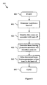
Figure 6 , such figure illustrates amethod 600 for efficient network hand-off, utilizing stored beam-forming information, in accordance with various aspects of the present invention. Themethod 600 may, for example and without limitation, be utilized in association with any of the communication systems and/or communication environments and scenarios illustrated inFigures 1-5 and discussed previously. - The
exemplary method 600 may begin executing atstep 605. Theexemplary method 600 may begin executing in response to any of a wide variety of causes or conditions. For example and without limitation, theexemplary method 600 may begin executing in response to a user or operator command. Also for example, theexemplary method 600 may begin executing in response to a detected condition (e.g., a condition detected in a communication environment). Additionally for example, theexemplary method 600 may begin executing in response to a start-up or reset condition. Further for example, theexemplary method 600 may begin executing in response to a communication beginning, occurring and/or ending. Still further for example, theexemplary method 600 may begin executing in response to a determination being made that a particular mobile communication device and/or a user thereof is associated with a particular type of communication service, quality of service and/or service plan. Accordingly, the scope of various aspects of the present invention should not be limited by characteristics of any particular initiating causes or conditions unless explicitly claimed. - The
exemplary method 600 may, atstep 610, comprise storing beam-forming information associated with a particular hand-off. Such storing may, for example, occur prior to a determination being made to perform the particular hand-off. For example, such storing may occur prior to a determination being made that the particular hand-off is imminent, going to occur relatively soon (e.g., during a present communication, during a particular time window, etc.), or going to occur in the relatively distant future. Such storing may also, for example, occur prior to a determination being made that the particular hand-off is probably going to occur or probably going to occur to a particular degree or threshold limit. - Step 610 may, for example, comprise storing the beam-forming information associated with a particular hand-off in apparatus of a communication network (e.g., at an access point, network controller, network database, etc.). In a non-limiting exemplary scenario, step 610 may comprise storing such beam-forming information for particularly common hand-off scenarios experienced by the access point (e.g., hand-offs with particular network access points, hotspots, mobile communication devices, etc.). Also for example, step 610 may comprise storing the beam-forming information at a central repository accessible by a plurality of different communication networks. Additionally for example, step 610 may comprise storing the beam-forming information at the mobile communication device. Then, for example, a mobile communication device may have beam-forming information stored therein that is associated with one or more hand-off scenarios commonly experienced by the mobile communication device. Further for example, step 610 may comprise storing such beam-forming information at the source and/or destination network for the hand-off. In a non-limiting exemplary scenario, step 610 may comprise storing such beam-forming information at a server associated with a particular wireless hotspot involved in the hand-off. Accordingly, the scope of various aspects of the present invention should not be limited by characteristics of a particular storage location for the beam-forming information, unless explicitly claimed.
- The stored beam-forming information may, for example, comprise any of a variety of characteristics associated with forming a directed communication beam. For example and without limitation, the stored beam-forming information may comprise respective timing and/or phase information associated with a plurality of antennas and/or associated transmitters and/or receivers. Also for example, the stored beam-forming information may comprise beam direction information. Additionally for example, the stored beam-forming information may comprise information associated with latency, time, transmit power, antenna element identification, transmitter and/or receiver identification, etc. Accordingly, the scope of various aspects of the present invention should not be limited by characteristics of particular beam-forming information unless explicitly claimed.
- Step 610 may comprise storing the beam-forming information associated with the particular hand-off in a manner such that the beam-forming information is accessible in any of a variety of manners. For example and without limitation, step 610 may comprise storing the beam-forming information in a manner that is accessible by hand-off location (e.g., exact location, approximate location, general area, coverage area, etc.). For example, step 610 may comprise storing the beam-forming information in a manner that is accessible by a relatively common hand-off location (e.g., a location of a particular wireless LAN or hotspot at which hand-offs are known to commonly occur, a location along a particular transportation route (e.g., automobile route, train route, pedestrian route, aircraft route, etc.) at which hand-offs are known to commonly occur, etc. In such a scenario, the beam-forming information may comprise information that may be utilized to direct a communication beam to the particular location.
- Also for example, step 610 may comprise storing the beam-forming information in a manner that is accessible by network identification. For example, step 610 may comprise storing the beam-forming information in a manner that is accessible by the identification of a particular network (or access point thereof) involved in a commonly occurring hand-off (e.g., the destination and/or source network of the hand-off). In a non-limiting exemplary scenario, step 610 may comprise storing beam-forming information for forming a communication beam directed at a particular wireless hotspot with which hand-offs frequently occur. For example, the exemplary scenario may comprise a wireless MAN and/or telecommunication network access point commonly involved in hand-offs with a particular wireless hotspot (e.g., at an office place, coffee shop, restaurant, club, etc.). In such an exemplary scenario, step 610 may comprise storing beam-forming information associated with forming a communication beam directed at the location of the identified hotspot. Thus, such stored beam-forming information may be readily accessible by the identification of the particular hotspot.
- Note that storing such beam-forming information in a manner accessible by location and/or network identification are merely examples. Such beam-forming information may be stored in a manner accessible by any of a variety of information types (e.g., accessible by communication network access point identity, mobile communication device identity, user identity, time, day, type-of-day, communication service identity, communication service plan identity, etc.).
- Step 610 may comprise storing the beam-forming information in a manner accessible by location and/or network identification information in any of a variety of manners. For example and without limitation, step 610 may comprise storing the beam-forming information in a manner that is indexed by location and/or network identification information (e.g., in a table form, linked list form, database form, using metadata tags, etc.). In a non-limiting exemplary scenario, particular beam-forming information that has been found to result in communication beams that perform particularly well for hand-offs associated with a particular location and/or network and/or network access point may be stored in a manner that associates the particular location and/or network with the stored beam-forming information. Accordingly, the scope of various aspects of the present invention should not be limited by characteristics of any particular implementation of storing the beam-forming information in a manner accessible by location and/or network (or access point) identification unless explicitly claimed.
- The
exemplary method 600 may, atstep 620, comprise determining to perform the particular communication hand-off. Step 620 may comprise determining to perform the particular communication hand-off in any of a variety of manners. For example and without limitation, step 620 may comprise determining to perform the particular communication hand-off based, at least in part, on signal and/or channel quality. Also for example, step 620 may comprise determining to perform the particular communication hand-off based, at least in part, on a request (e.g., a user request, operator request, etc.). Further for example, step 620 may comprise determining to perform the particular communication hand-off based, at least in part, on a hand-off profile associated with a particular user, communication network, communication service, etc. Accordingly, the scope of various aspects of the present invention should not be limited by characteristics of any particular manner of determining to perform a communication hand-off unless explicitly claimed. - In a non-limiting exemplary scenario, step 620 may comprise determining that a mobile communication device is entering and/or leaving the coverage area associated with a particular wireless LAN. Step 620 may make such a determination based, at least in part, on communication channel conditions between the MCD and the hotspot and/or based, at least in part, on communication channel conditions between another communication network access point and the MCD.
- The
exemplary method 600 may, atstep 630, comprise accessing the stored beam-forming information (e.g., stored at step 610). For example and without limitation, step 630 may comprise accessing the stored beam-forming information after determining to perform a particular hand-off (e.g., as determined at step 620). For example, such a determination may result in initiation of hand-off activities. Also for example, step 630 may comprise accessing the stored beam-forming information after determining that performing a particular hand-off is imminent (i.e., going to occur) but before determining a hand-off time. Additionally for example, step 630 may comprise accessing the stored beam-forming information after determining that performing a particular hand-off is probably (e.g., statistically probable, likely, highly likely, etc.) going to occur but it is not definite that the hand-off is going to occur. - Step 630 may comprise accessing the stored beam-forming information in any of a variety of manners. For example and without limitation, step 630 may comprise accessing the stored beam-forming information based, at least in part, on location information, network and/or access point identity information, communication device identity, user identity information, time and/or day information, distance and/or direction information etc.
- In a first non-limiting exemplary scenario, step 630 may comprise determining a location (e.g., an exact location, approximate location, general location, locale, region, coverage area, etc.) associated with the particular hand-off, and accessing the stored beam-forming information based, at least in part, on information of the determined location. Such a location may be determined in any of a variety of manners. For example and without limitation, step 630 may comprise determining the location by receiving location information (e.g., at the mobile communication device and/or a communication network associated with the hand-off) from a positioning system (e.g., the Global Positioning System ("GPS")). Also for example, step 630 may comprise receiving positioning information from a communication network (e.g., from a server associated with a hotspot or a system performing triangulation). Further for example, step 630 may comprise retrieving location information from a memory (e.g., from a memory of the mobile communication device and/or communication network). Still further for example, step 630 may comprise determining a location associated with a known network (e.g., WLAN location, WPAN location, etc.). Also for example, step 630 may comprise determining a location associated with a particular communication network access point and/or coverage area (e.g., WMAN access point, cellular base station, etc.). Additionally for example, step 630 may comprise determining a location based, at least in part, on information input from a user of a communication device being handed off and/or an operator of a communication network. In yet another example, step 630 may comprise predicting a location associated with a particular hand-off (e.g., based on monitored behavior, travel patterns, hand-off patterns, interpolation, etc.). In still another example, step 630 may comprise determining location information utilizing UltraWideBand ("UWB") techniques. Accordingly, the scope of various aspects of the present invention should not be limited by characteristics of any particular manner of determining location unless explicitly claimed.
- Location information may comprise characteristics of any of a variety of types of location information. For example and without limitation, the location information may comprise information of geographical coordinates (e.g., based on any of a number of geographical location systems), street addresses, landmarks, building identity and/or location, business identity and/or location, entertainment venue identity, intersections, transportation hub identity, etc. Note that such location information may also, for example, comprise location information corresponding to network location (e.g., hand-off source network and/or hand-off recipient network) and mobile communication device location. Accordingly, the scope of various aspects of the present invention should not be limited by characteristics of any particular type of location information unless explicitly claimed.
- As mentioned previously,
step 630 may comprise utilizing location information to access the stored beam-forming information. For example and without limitation, step 630 may comprise utilizing location information as an index (or one of a plurality of indices) to access particular stored beam-forming information. Also for example, step 630 may comprise utilizing location information as a database search criterion to search for particular stored beam-forming information. Further for example, step 630 may comprise utilizing location information as general search criteria for beam-forming information. Accordingly, the scope of various aspects of the present invention should not be limited by characteristics of any particular manner of utilizing location information to access beam-forming information, unless explicitly claimed. - In another non-limiting exemplary scenario, step 630 may comprise identifying a communication network (e.g., by name, by network address (e.g., IP address), by arbitrary tag, etc.) associated with the particular hand-off, and accessing the stored beam-forming information based, at least in part, on information of the network identity. Network identity may be determined in any of a variety of manners. For example and without limitation, step 630 may comprise determining network identity through direct communication with the network and/or through communication with a communication network associated with the network. Also for example, step 630 may comprise determining network identity through communication with a mobile communication device (e.g., the mobile communication device to be handed off to or from the network). Further for example, step 630 may comprise utilizing determined location information to ascertain network identity. Also for example, step 630 may comprise determining network identity based, at least in part, on transmissions from the network (e.g., beacons, typical data messages, control messages, synchronization signals, etc.). Accordingly, the scope of various aspects of the present invention should not be limited by characteristics of any particular manner of determining network identity.
- As mentioned previously,
step 630 may comprise utilizing network identity to access the stored beam-forming information. For example and without limitation, step 630 may comprise utilizing network identity information as an index (or one of a plurality of indices) to access particular stored beam-forming information. Also for example, step 630 may comprise utilizing network identity information as a database search criterion to search for particular stored beam-forming information. Further for example, step 630 may comprise utilizing network identity information as general search criteria for beam-forming information. Accordingly, the scope of various aspects of the present invention should not be limited by characteristics of any particular manner of utilizing network identity information to access beam-forming information, unless explicitly claimed. - In another non-limiting exemplary scenario, step 630 may comprise identifying an access point of a communication network (e.g., by name, by address (e.g., IP address), by arbitrary tag, etc.) associated with the particular hand-off, and accessing the stored beam-forming information based, at least in part, on information of the access point identity. Note that hand-offs may be performed between access points of a same communication network and/or between access points of different respective networks.
- Access point identity may be determined in any of a variety of manners. For example and without limitation, step 630 may comprise determining access point identity through direction communication with the access point and/or through communication with a network controller or other apparatus of a communication network associated with the access point. Also for example, step 630 may comprise determining access point identity through communication with a mobile communication device (e.g., the mobile communication device to be handed off to or from the access point). Further for example, step 630 may comprise utilizing determined location information to ascertain access point identity. Also for example, step 630 may comprise determining access point identity based, at least in part, on transmissions from the access point (e.g., beacons, typical data messages, control messages, synchronization signals, etc.) or other access points associated therewith. Accordingly, the scope of various aspects of the present invention should not be limited by characteristics of any particular manner of determining access point identity.
- As mentioned previously,
step 630 may comprise utilizing access point identity to access the stored beam-forming information. For example and without limitation, step 630 may comprise utilizing access point identity information as an index (or one of a plurality of indices) to access particular stored beam-forming information. Also for example, step 630 may comprise utilizing access point identity information as a database search criterion to search for particular stored beam-forming information. Further for example, step 630 may comprise utilizing access point identity information as general search criteria for beam-forming information. Accordingly, the scope of various aspects of the present invention should not be limited by characteristics of any particular manner of utilizing access point identity information to access beam-forming information, unless explicitly claimed. - The previous examples present the determination and/or utilization of location, network identity and access point identity to access stored beam-forming information. Note that such examples are non-limiting illustrations and many other manners of accessing the stored beam-forming information, some of which were presented above, are contemplated. Additionally, any combination of the various manners is contemplated. For example and without limitation, any combination of location, network identity, access point identity, mobile communication device identity, user identity, time information, day information, service type, service availability, service plan provisions, etc., may be utilized to access stored beam-forming information.
- The
exemplary method 600 may, atstep 640, comprise utilizing the accessed beam-forming information (e.g., accessed at step 630) to form a communication beam to utilize for performing the particular hand-off. For example and without limitation, step 640 may comprise utilizing the accessed beam-forming information to form a communication beam prior to determining when to perform the particular hand-off. Also for example, step 640 may comprise utilizing the accessed beam-forming information to form a communication beam prior to triggering the particular hand-off. In another example, step 640 may comprise utilizing the accessed beam-forming information to form a communication beam prior to determining when the particular hand-off is imminent (e.g., based on a degree of likelihood, for example, statistically based degree of likelihood). - Note that
step 640 may comprise utilizing the formed communication beam to perform a hand-off (e.g., of a mobile communication device) in any of a variety of manners. For example and without limitation, step 640 may comprise forming the communication beam and utilizing the formed communication beam at the source network (or access point) of the hand-off and/or the recipient network (or access point). For example, not all networks involved in the hand-off need utilize beam forming. Also for example, as discussed previously with regard toFigure 5 , a hand-off may be performed between access points of a same communication network, between different communication networks of the same type and/or between different types of communication networks. - The
exemplary method 600 may, atstep 695 comprise performing continued processing. Such continued processing may comprise performing any of a variety of communication activities, non-limiting examples of which are provided below. - For example and without limitation, step 695 may comprise adapting the stored beam-forming information. In a non-limiting exemplary scenario, the communication system(s) implementing the
exemplary method 600 may determine that the accessed (e.g., at step 630) stored (e.g., at step 610) beam-forming information should be modified. Such a determination may, for example, be based on changing communication environment, etc. In such a scenario, step 695 may comprise determining adjustments to make to the accessed beam-forming information and/or determining new beam-forming information. Such adapted beam-forming information may then be stored (e.g., in a manner similar to that discussed previously with regard to step 610). - Also for example, step 695 may comprise switching from communicating with a handed-off mobile communication device using beam-forming to communicating with the handed-off mobile communication device utilizing single antenna communication, Single-Input-Single-Output ("SISO") communication, MIMO communication, Multiple-Input-Single-Output ("MISO") communication, etc. As discussed previously, a communication device (e.g., an access point and/or mobile communication device) may comprise various characteristics of the
exemplary systems Figures 1-3 . Thus, such systems may switch between various forms of communicating utilizing one or more antennas and/or associated transceivers. - Further for example, step 695 (or a portion of step 640) may comprise handing off one or more communication services being provided to the communication device handed off. In a non-limiting exemplary scenario, prior to performing a hand-off, the source communication network may be providing a communication service to the mobile communication device (and/or a user thereof). In the exemplary scenario, the formed communication beam may be utilized to hand off the mobile communication device from the source communication network to a destination communication network. Continuing the exemplary scenario, the destination communication network may then continue providing the communication service to the mobile communication device. Many non-limiting examples of such a communication service were provided previously. Note that in such an exemplary scenario, the communication service may be one of a plurality of communication services presently being provided to the mobile communication device by respective communication networks. All or only a portion of such communication services might be handed off.
- In general,
Figure 6 illustrates amethod 600 for efficient network hand-off, utilizing stored beam-forming information. The following discussion ofFigures 7 and8 will provide non-limiting examples of other aspects that may be implemented independently of various steps of theexemplary method 600 illustrated inFigure 6 and/or in conjunction with various steps of theexemplary method 600 illustrated inFigure 6 . - Turning next to
Figure 7 , such figure is a flow diagram illustrating amethod 700 for efficient network hand-off, associating location information with beam-forming information, in accordance with various aspects of the present invention. Theexemplary method 700 may, for example and without limitation, share any or all characteristics with theexemplary method 600 illustrated inFigure 6 and discussed previously. Additionally, theexemplary method 700 may be implemented by a communication system sharing any or all characteristics with theexemplary communication systems Figures 1-3 and discussed previously. Further, theexemplary method 700 may be implemented in a communication environment sharing any or all characteristics with theexemplary environments Figures 4-5 and discussed previously. - The
exemplary method 700 may begin executing atstep 705. Theexemplary method 700 may begin executing in response to any of a wide variety of causes or conditions. For example and without limitation, theexemplary method 700 may begin executing in response to a user or operator command. Also for example, theexemplary method 700 may begin executing in response to a detected condition (e.g., a condition detected in a communication environment). Additionally for example, theexemplary method 700 may begin executing in response to a start-up or reset condition. Further for example, theexemplary method 700 may begin executing in response to a communication beginning, occurring and/or ending. Still further for example, theexemplary method 700 may begin executing in response to a determination being made that a particular mobile communication device and/or a user thereof is associated with a particular type of communication service, quality of service and/or service plan. Additionally, theexemplary method 700 may begin executing in response to a determination that a hand-off is imminent, likely, probably, highly likely, etc. Accordingly, the scope of various aspects of the present invention should not be limited by characteristics of any particular initiating causes or conditions unless explicitly claimed. - The
exemplary method 700 may, atstep 710, comprise determining to perform a hand-off. Step 710 may, for example and without limitation, share any or all characteristics withstep 620 of theexemplary method 600 illustrated inFigure 6 and discussed previously. - The
exemplary method 700 may, atstep 720, comprise determining a location of (or associated with) a hand-off target (e.g., a mobile communication device to be handed off). Step 720 may comprise determining the location of the hand-off target in any of a variety of manners. For example and without limitation, step 720 may share any or all characteristics withstep 630 of theexemplary method 600 illustrated inFigure 6 and discussed previously. - In a first non-limiting exemplary scenario, step 720 may comprise determining a location (e.g., an exact location, approximate location, general location, locale, region, coverage area, etc.) associated with the particular hand-off (e.g., a location of a mobile communication device being handed off). Such a location may be determined in any of a variety of manners. For example and without limitation, step 720 may comprise determining the location by receiving location information (e.g., at the mobile communication device being handed off and/or a communication network associated with the hand-off) from a positioning system (e.g., the Global Positioning System). Also for example, step 720 may comprise receiving positioning information from a communication network (e.g., from a server associated with a hotspot or a system performing triangulation). Further for example, step 720 may comprise retrieving location information from a memory (e.g., from a memory of the mobile communication device being handed off and/or a memory of (or accessible by) communication network). Still further for example, step 720 may comprise determining a location associated with a known network (e.g., WLAN location, WPAN location, etc. that may be in communication with the mobile communication device before being handed off or that will be in communication with the mobile communication device after being handed off). Also for example, step 720 may comprise determining a location associated with a particular communication network access point and/or coverage area (e.g., WMAN access point, cellular base station, etc. that is in communication with the mobile communication device before being handed off or that will be in communication with the mobile communication device after hand-off). Additionally for example, step 720 may comprise determining a location based, at least in part, on information input from a user of a mobile communication device being handed off and/or an operator of a communication network. In yet another example, step 720 may comprise predicting (e.g., interpolating) a location of a mobile communication device associated with a particular hand-off (e.g., based on monitored behavior, travel patterns, hand-off patterns, etc.). Accordingly, the scope of various aspects of the present invention should not be limited by characteristics of any particular manner of determining location unless explicitly claimed.
- As discussed previously, location information associated with the determined location may comprise characteristics of any of a variety of types of location information. For example and without limitation, the location information may comprise information of geographical coordinates (e.g., based on any of a number of geographical location systems), street addresses, landmarks, building identity and/or location, business identity and/or location, entertainment venue identity, intersections, transportation hub identity, etc. Note that such location information may also, for example, comprise location information corresponding to network location (e.g., hand-off source network and/or hand-off recipient network) and/or mobile communication device location. Accordingly, the scope of various aspects of the present invention should not be limited by characteristics of any particular type of location information unless explicitly claimed.
- The
exemplary method 700 may, atstep 730, comprise determining beam-forming parameters associated with the hand-off location (e.g., as determined at step 720). Step 730 may comprise determining the beam-forming parameters in any of a variety of manners. For example and without limitation, step 730 may comprise accessing stored beam-forming parameters associated with the determined location. Non-limiting examples of such access were discussed previously with regard to step 630 of theexemplary method 600 illustrated inFigure 6 . - Also for example, step 730 may comprise calculating the beam-forming parameters as a function of the determined location (e.g., as a function of a beam direction associated with the determined location). For example, step 730 may comprise determining timing and/or phase relationships corresponding to various antennas and/or transmitters and/or receivers for directing a beam of a particular shape to the determined location. Also for example, step 730 may comprise determining beam-forming parameters as a combination of accessed stored beam-forming information and calculated adjustments to such accessed stored information. Accordingly, the scope of various aspects of the present invention should not be limited by characteristics of any particular manner of determining beam-forming parameters associated with a determined location unless explicitly claimed.
- The
exemplary method 700 may, atstep 740, comprise utilizing determined beam-forming parameters (e.g., as determined at step 730) to form a communication beam (e.g., a transmission and/or reception beam) to utilize in performing the hand-off. Step 740 may, for example and without limitation, share any or all characteristics withstep 640 of theexemplary method 600 illustrated inFigure 6 and discussed previously. - The
exemplary method 700 may, atstep 795, comprise continuing to perform additional communication activities. For example and without limitation, step 795 may share any or all characteristics withstep 695 of theexemplary method 600 illustrated inFigure 6 and discussed previously. - Turning next to
Figure 8 , such figure is a flow diagram illustrating amethod 800 for efficient network hand-off, associating network identification with beam-forming information, in accordance with various aspects of the present invention. Theexemplary method 800 may, for example and without limitation, share any or all characteristics with theexemplary methods Figures 6-7 and discussed previously. Additionally, theexemplary method 800 may be implemented by a communication system sharing any or all characteristics with theexemplary communication systems Figures 1-3 and discussed previously. Further, theexemplary method 800 may be implemented in a communication environment sharing any or all characteristics with theexemplary environments Figures 4-5 and discussed previously. - The
exemplary method 800 may begin executing atstep 805. Theexemplary method 800 may begin executing in response to any of a wide variety of causes or conditions. For example and without limitation, step 805 may share any or all characteristics withsteps exemplary methods Figures 6-7 and discussed previously. - The
exemplary method 800 may, atstep 810, comprise determining to perform a hand-off. Step 810 may, for example and without limitation, share any or all characteristics withsteps exemplary methods Figures 6-7 and discussed previously. - The
exemplary method 800 may, atstep 820, comprise identifying one or more communication networks (or access points) associated with the hand-off (e.g., a communication network sourcing and/or receiving a mobile communication device hand-off). Step 820 may comprise determining the location of the hand-off target in any of a variety of manners. For example and without limitation, step 820 may share any or all characteristics withstep 630 of theexemplary method 600 illustrated inFigure 6 and discussed previously. - For example and without limitation, step 820 may comprise determining network identity through direct communication with the network and/or through communication with a communication network associated with the network. Also for example, step 820 may comprise determining network identity through communication with a mobile communication device (e.g., the mobile communication device to be handed off to or from the network). Further for example, step 820 may comprise utilizing determined location information to ascertain network identity. Also for example, step 820 may comprise determining network identity based, at least in part, on transmissions from the network (e.g., beacons, typical data messages, control messages, synchronization signals, etc.). Accordingly, the scope of various aspects of the present invention should not be limited by characteristics of any particular manner of determining network identity.
- The
exemplary method 800 may, atstep 830, comprise determining beam-forming parameters associated with one or more identified communication networks (e.g., identified at step 820). Step 830 may, for example and without limitation, share any or all characteristics withsteps Figures 6-7 and discussed previously. - Step 830 may comprise determining the beam-forming parameters in any of a variety of manners. For example and without limitation, step 830 may comprise accessing stored beam-forming parameters associated with the identified communication network(s). Non-limiting examples of such access were discussed previously with regard to step 630 of the
exemplary method 600 illustrated inFigure 6 . - Also for example, step 830 may comprise calculating the beam-forming parameters as a function of the identified communication network(s) (e.g., as a function of a beam direction associated with the identified communication network(s)). For example, step 830 may comprise determining timing and/or phase relationships corresponding to various antennas and/or transmitters and/or receivers for directing a beam of a particular shape to the identified communication network(s). Also for example, step 830 may comprise determining beam-forming parameters as a combination of accessed stored beam-forming information and calculated adjustments to such accessed stored information. Accordingly, the scope of various aspects of the present invention should not be limited by characteristics of any particular manner of determining beam-forming parameters associated with one or more identified communication networks unless explicitly claimed.
- The
exemplary method 800 may, atstep 840, comprise utilizing determined beam-forming parameters (e.g., as determined at step 830) to form a communication beam (e.g., a transmission and/or reception beam) to utilize in performing the hand-off. Step 840 may, for example and without limitation, share any or all characteristics withsteps exemplary methods Figures 6-7 and discussed previously. - The
exemplary method 800 may, atstep 895, comprise continuing to perform additional communication activities. For example and without limitation, step 895 may share any or all characteristics withstep 695 of theexemplary method 600 illustrated inFigure 6 and discussed previously. - Turning next to
Figure 9 , such figure is a diagram illustrating a non-limiting exemplary block diagram of acommunication device 900 that operates to perform efficient network hand-off utilizing beam forming in accordance with various aspects of the present invention. Thecommunication device 900 may, for example, be a mobile communication device, a network access point or base station, a network controller or other network infrastructure component or subsystem, an integrated circuit, an insertible communication module, etc. Thecommunication device 900 may, for example, share any or all characteristics with theexemplary communication systems Figures 1-3 and discussed previously. Also for example, thecommunication device 900 may share characteristics with themobile communication devices 405 and MCD1 illustrated inFigures 4-5 and discussed previously. Additionally for example, the communication device 900 (or components or modules thereof) may share any or all functional characteristics with theexemplary methods Figures 6-8 and discussed previously. Note that theexemplary communication device 900 may perform various aspects of the present invention in hardware and/or software. - The
exemplary communication device 900 may comprise awireless 905 and/or wired 906 front end, which may operate to communicate through any of a wide variety of communication media. Theexemplary communication device 900 may also comprise a variety ofcommunication interface modules 910, which may operate to communicate with any of a wide variety of communication networks utilizing any of a wide variety of communication protocols, some of which are specified in the illustration atitem 910. - The
exemplary communication device 900 may also comprise a variety of signal processing modules (e.g., hardware and/or software modules) that operate to perform a variety of signal processing functions, non-limiting examples of which were provided previously in the discussion ofFigures 6-8 . Additionally, theexemplary communication device 900 may comprise a processor 960 (e.g., a baseband processor, general microprocessor, digital signal processor, etc.) that operates to execution software or firmware instructions (e.g., applications and/or subroutines) stored in a memory 950 (on-board theprocessor 960 or separate from the processor 960). Such aprocessor 960 may thus perform any of the functionality discussed previously. - The
exemplary communication device 900 may further comprise any of a variety ofuser interface modules 940. Suchuser interface modules 940 may operate to assist with providing communication services to a user and/or to communicate general input and output information with a user of thecommunication device 900. - In summary, various aspects of the present invention provide a system and method for performing efficient network hand-off utilizing beam-forming information. While the invention has been described with reference to certain aspects and embodiments, it will be understood by those skilled in the art that various changes may be made and equivalents may be substituted without departing from the scope of the invention. In addition, many modifications may be made to adapt a particular situation or material to the teachings of the invention without departing from its scope. Therefore, it is intended that the invention not be limited to the particular embodiment disclosed, but that the invention will include all embodiments falling within the scope of the appended claims.
Advantageously, accessing stored beam-forming information associated with the particular hand-off to be performed comprises:
Advantageously, the method further comprises after utilizing the accessed beam-forming information to form a communication beam to utilize for performing the particular hand-off, adapting the stored beam-forming information associated with the particular hand-off.
Advantageously, the method further comprises after utilizing the accessed beam-forming information to form a communication beam to utilize for performing the particular hand-off, switching from a beam-forming configuration to a Multiple Input Multiple Output (MIMO) configuration.
Advantageously, the method further comprises:
Advantageously, the communication service is one of a plurality of communication services being provided to the mobile communication device at the time of the hand-off, less than all of which are associated with the hand-off.
Advantageously, the particular hand-off concerns handing off a mobile communication device comprising cellular telephone capability.
Advantageously, the method further comprises utilizing the formed communication beam to perform the particular hand-off, where the particular hand-off comprises handing off a mobile communication device from a first communication network to a second communication network different from the first communication network.
Advantageously, the method further comprises utilizing the formed communication beam to perform the particular hand-off, where the particular hand-off comprises handing off a mobile communication device from a first communication network of a first type to a second communication network of a second type different from the first type. Advantageously:
Advantageously, the at least one module operates to store beam-forming information associated with the particular hand-off by, at least in part, operating to store the beam-forming information at an access point of a communication network.
Advantageously, the at least one module operates to store beam-forming information associated with the particular hand-off by, at least in part, operating to store the beam-forming information in a manner that is accessible by hand-off location.
Advantageously, the at least one module operates to store beam-forming information associated with the particular hand-off by, at least in part, operating to store the beam-forming information in a manner that is accessible by network identification.
Advantageously, the at least one module operates to access the stored beam-forming information associated with the particular hand-off to be performed by, at least in part, operating to:
Advantageously, the at least one module operates to access the stored beam-forming information associated with the particular hand-off to be performed by, at least in part, operating to:
Advantageously, after operating to utilize the accessed beam-forming information to form a communication beam to utilize for performing the particular hand-off, the at least one module operates to adapt the stored beam-forming information associated with the particular hand-off.
Advantageously, after operating to utilize the accessed beam-forming information to form a communication beam to utilize for performing the particular hand-off, the at least one module operates to switch from a beam-forming configuration to a Multiple Input Multiple Output (MIMO) configuration.
Advantageously, the at least one module further operates to, at least:
Advantageously, the communication service is one of a plurality of communication services being provided to the mobile communication device at the time of the hand-off, less than all of which are associated with the hand-off.
Advantageously, the particular hand-off concerns handing off a mobile communication device comprising cellular telephone capability.
Advantageously, the at least one module further operates to utilize the formed communication beam to perform the particular hand-off, where the particular hand-off comprises handing off a mobile communication device from a first communication network to a second communication network different from the first communication network.
Advantageously, the at least one module further operates to utilize the formed communication beam to perform the particular hand-off, where the particular hand-off comprises handing off a mobile communication device from a first communication network of a first type to a second communication network of a second type different from the first type.
Advantageously, the processor comprises hardware and software.
Advantageously, the processor is a baseband processor.
Advantageously, the processor is an application-specific integrated circuit.
These and other advantages, aspects and novel features of the present invention, as well as details of illustrative aspects thereof, will be more fully understood from the following description and drawings.
Claims (10)
- A method in a communication system for performing communication device hand-off, the method comprising:determining (620) to perform a particular hand-off;accessing (630) stored beam-forming information associated with the particular hand-off to be performed; andutilizing (640) the accessed beam-forming information to form a communication beam to utilize for performing the particular hand-off.
- The method of claim 1, further comprising storing (610) beam-forming information associated with the particular hand-off before determining to perform the particular hand-off, and wherein accessing stored beam-forming information associated with the particular hand-off to be performed comprises accessing the stored beam-forming information associated with the particular hand-off after determining to perform the particular hand-off.
- The method of claim 2, wherein storing beam-forming information associated with the particular hand-off before determining to perform the particular hand-off comprises storing beam-forming information associated with the particular hand-off before determining that performance of the particular hand-off is imminent.
- The method of claim 2, wherein storing beam-forming information associated with the particular hand-off comprises storing the beam-forming information at an access point of a communication network.
- The method of claim 2, wherein storing beam-forming information associated with the particular hand-off comprises storing the beam-forming information in a manner that is accessible by hand-off location.
- The method of claim 2, wherein storing beam-forming information associated with the particular hand-off comprises storing the beam-forming information in a manner that is accessible by network identification.
- A processor (960) for facilitating communication device hand-off, the processor (960) comprising
at least one module that is adapted to, at least:determine to perform the particular hand-off;access stored beam-forming information associated with the particular hand-off to be performed; andutilize the accessed beam-forming information to form a communication beam to utilize for performing the particular hand-off. - The processor (960) of claim 7, wherein:the at least one module is further adapted to store beam-forming information associated with the particular hand-off before determining to perform the particular hand-off; andthe at least one module is further adapted to access stored beam-forming information associated with the particular hand-off to be performed by, at least in part, operating to access the stored beam-forming information associated with the particular hand-off after determining to perform the particular hand-off.
- The processor (960) of claim 8, wherein the at least one module is further adapted to store beam-forming information associated with the particular hand-off before determining to perform the particular hand-off by, at least in part, operating to store beam-forming information associated with the particular hand-off before determining that performance of the particular hand-off is imminent.
- The processor (960) of claim 8, wherein the at least one module is further adapted to store beam-forming information associated with the particular hand-off by, at least in part, operating to store the beam-forming information at an access point of a communication network.
Applications Claiming Priority (2)
| Application Number | Priority Date | Filing Date | Title |
|---|---|---|---|
| US88747107P | 2007-01-31 | 2007-01-31 | |
| US12/020,869 US20080181180A1 (en) | 2007-01-31 | 2008-01-28 | Efficient network hand-off utilizing stored beam-forming information |
Publications (3)
| Publication Number | Publication Date |
|---|---|
| EP1954091A2 EP1954091A2 (en) | 2008-08-06 |
| EP1954091A3 EP1954091A3 (en) | 2011-07-06 |
| EP1954091B1 true EP1954091B1 (en) | 2012-07-11 |
Family
ID=39522303
Family Applications (1)
| Application Number | Title | Priority Date | Filing Date |
|---|---|---|---|
| EP08001746A Active EP1954091B1 (en) | 2007-01-31 | 2008-01-30 | Efficient network hand-off utilizing stored beam-forming information |
Country Status (2)
| Country | Link |
|---|---|
| US (2) | US20080181180A1 (en) |
| EP (1) | EP1954091B1 (en) |
Families Citing this family (33)
| Publication number | Priority date | Publication date | Assignee | Title |
|---|---|---|---|---|
| US8254913B2 (en) | 2005-08-18 | 2012-08-28 | Smartsky Networks LLC | Terrestrial based high speed data communications mesh network |
| US8260360B2 (en) * | 2007-06-22 | 2012-09-04 | Broadcom Corporation | Transceiver with selective beamforming antenna array |
| DE602009000531D1 (en) * | 2008-09-04 | 2011-02-17 | Alcatel Lucent | Systems and methods for providing broadband mobile communication services on board an aircraft |
| EP2373105A1 (en) | 2008-12-26 | 2011-10-05 | Panasonic Corporation | Wireless base station, wireless terminal, and channel signal formation method |
| KR101631477B1 (en) * | 2009-08-05 | 2016-06-17 | 삼성전자주식회사 | Communication system for adaptively using single-point trnasmission/reception and coordinated multi-point trnasmission/reception |
| PT2580811T (en) * | 2010-06-11 | 2018-06-12 | Ericsson Telefon Ab L M | A node in a communication system with switchable antenna functions |
| US8780859B2 (en) * | 2010-07-15 | 2014-07-15 | CSC Holdings, LLC | Efficient use of a communications network |
| WO2013006105A1 (en) | 2011-07-07 | 2013-01-10 | Telefonaktiebolaget L M Ericsson (Publ) | A method in a base station of a communication system for making a handover decision, base station, computer programs, and computer program products |
| CN103052124A (en) * | 2011-10-14 | 2013-04-17 | 西门子公司 | Client, access point, communication system and switching method |
| US20140148155A1 (en) * | 2012-11-28 | 2014-05-29 | Motorola Solutions, Inc. | Method and apparatus for implementing transmit beamforming |
| US20140349696A1 (en) * | 2013-03-15 | 2014-11-27 | Elwha LLC, a limited liability corporation of the State of Delaware | Supporting antenna assembly configuration network infrastructure |
| US9241357B2 (en) * | 2013-06-27 | 2016-01-19 | Kabushiki Kaisha Toshiba | Electronic device, method, and computer-readable storage medium |
| US9357534B2 (en) | 2013-08-09 | 2016-05-31 | Qualcomm Incorporated | Method and apparatus for location aided high frequency operations |
| GB2522603A (en) * | 2013-10-24 | 2015-08-05 | Vodafone Ip Licensing Ltd | High speed communication for vehicles |
| US10097321B2 (en) * | 2014-05-08 | 2018-10-09 | Qualcomm Incorporated | Cooperative techniques between lower-frequency carriers and millimeter-wave channels for discovery and synchronization and beamforming |
| WO2016003335A1 (en) * | 2014-07-02 | 2016-01-07 | Telefonaktiebolaget L M Ericsson (Publ) | Method and network node for calibrating uplink measurements to offset beamforming of neighbouring nodes |
| CN106576272B (en) | 2014-07-02 | 2020-09-25 | 瑞典爱立信有限公司 | Method and apparatus for obtaining accurate measurements of communication devices |
| US20170245192A1 (en) * | 2014-08-28 | 2017-08-24 | Intel Corporation | Apparatus, system and method of communicating with a vehicle along a transportation route |
| US10334489B2 (en) | 2014-10-08 | 2019-06-25 | Telefonaktiebolaget Lm Ericsson (Publ) | Mobility synchronization measurements |
| US9668189B2 (en) * | 2014-11-14 | 2017-05-30 | Industrial Technology Research Institute | Handover management method and base station using the same |
| KR102258575B1 (en) * | 2015-03-17 | 2021-05-31 | 삼성전자 주식회사 | Electronic apparatus and method for wireless communication using beamforming thereof |
| JP6439859B2 (en) * | 2015-03-23 | 2018-12-19 | 日本電気株式会社 | Base station apparatus, communication system and communication method |
| US9668100B2 (en) | 2015-04-03 | 2017-05-30 | International Business Machines Corporation | Locating misplaced mobile computing devices |
| CN107667481A (en) * | 2015-04-07 | 2018-02-06 | 三星电子株式会社 | Method and apparatus for handover in a wireless communication system using beamforming |
| WO2017067580A1 (en) * | 2015-10-20 | 2017-04-27 | Telefonaktiebolaget Lm Ericsson (Publ) | Determination of reference signal transmission pattern |
| WO2017184190A1 (en) * | 2016-04-18 | 2017-10-26 | Intel Corporation | Selection of beamforming directions based on learned performance |
| US10432276B2 (en) | 2016-09-29 | 2019-10-01 | Intel IP Corporation | Wireless link control and recovery using positional data |
| US10863399B2 (en) * | 2017-05-04 | 2020-12-08 | Qualcomm Incorporated | Predictive beamforming and subarray selection |
| JP7003497B2 (en) * | 2017-09-01 | 2022-01-20 | 日本電気株式会社 | First base station |
| US12335750B2 (en) | 2020-01-14 | 2025-06-17 | Telefonaktiebolaget Lm Ericsson (Publ) | Methods of managing communication based on information defining an operational environment and related nodes |
| US12034582B2 (en) | 2021-03-05 | 2024-07-09 | Peraton Labs Inc. | Adaptive radio frequency communication |
| US11658755B2 (en) | 2021-03-05 | 2023-05-23 | Perspecta Labs Inc. | Interference mitigation in multi-antenna system |
| CN115843021A (en) * | 2021-09-18 | 2023-03-24 | 维沃移动通信有限公司 | Data transmission method and device |
Family Cites Families (15)
| Publication number | Priority date | Publication date | Assignee | Title |
|---|---|---|---|---|
| US6108538A (en) * | 1997-12-01 | 2000-08-22 | Motorola, Inc. | Method and apparatus for dynamically controlling hand-off thresholds in a satellite cellular communication system |
| GB9927517D0 (en) * | 1999-11-23 | 2000-01-19 | Motorola Ltd | Adaptive antenna and network incorporating same |
| US6711408B1 (en) * | 2000-02-05 | 2004-03-23 | Ericsson Inc. | Position assisted handoff within a wireless communications network |
| US6721567B1 (en) * | 2000-03-30 | 2004-04-13 | Nokia Corporation | Apparatus, and an associated method, for selecting a likely target cell in a cellular communication system |
| EP1220475A3 (en) * | 2000-12-25 | 2003-11-19 | Kabushiki Kaisha Toshiba | Mobile communication terminal apparatus with antenna array |
| US6697644B2 (en) * | 2001-02-06 | 2004-02-24 | Kathrein-Werke Kg | Wireless link quality using location based learning |
| US6829481B2 (en) * | 2001-05-15 | 2004-12-07 | Novatel Wireless, Inc. | Systems and methods for intelligent inter-system handoff |
| DE10124397A1 (en) * | 2001-05-18 | 2002-11-21 | Siemens Ag | Method for controlling beam shaping for a download signal beams the signal to a mobile station in a mobile telephone system of base stations for first and second radio cells. |
| US20040058678A1 (en) * | 2002-09-23 | 2004-03-25 | Detorbal Rene Fernand Emile | Method and apparatus for facilitating handovers for a group of mobile radios |
| US20050070285A1 (en) * | 2003-09-29 | 2005-03-31 | Telefonaktiebolaget Lm Ericsson (Publ) | Handover for use with adaptive antennas |
| US7933599B2 (en) * | 2005-03-29 | 2011-04-26 | Qualcomm Incorporated | Techniques for facilitating communication handoffs |
| US8280309B2 (en) * | 2005-04-08 | 2012-10-02 | The Boeing Company | Soft handoff method and apparatus for mobile vehicles using directional antennas |
| JP4639257B2 (en) * | 2005-05-18 | 2011-02-23 | テルコーディア ライセンシング カンパニー, リミテッド ライアビリティ カンパニー | Seamless handoff between heterogeneous access networks using a service control point handoff controller |
| JP4727678B2 (en) * | 2006-02-08 | 2011-07-20 | 富士通株式会社 | Wireless communication system using multi-antenna transmission technology and multi-user scheduler applied to the same |
| US8036669B2 (en) * | 2006-04-20 | 2011-10-11 | Qualcomm Incorporated | Orthogonal resource reuse with SDMA beams |
-
2008
- 2008-01-28 US US12/020,869 patent/US20080181180A1/en not_active Abandoned
- 2008-01-30 EP EP08001746A patent/EP1954091B1/en active Active
-
2014
- 2014-01-30 US US14/168,844 patent/US9288736B2/en not_active Expired - Fee Related
Also Published As
| Publication number | Publication date |
|---|---|
| US20080181180A1 (en) | 2008-07-31 |
| US9288736B2 (en) | 2016-03-15 |
| US20140148173A1 (en) | 2014-05-29 |
| EP1954091A2 (en) | 2008-08-06 |
| EP1954091A3 (en) | 2011-07-06 |
Similar Documents
| Publication | Publication Date | Title |
|---|---|---|
| EP1954091B1 (en) | Efficient network hand-off utilizing stored beam-forming information | |
| US12363623B2 (en) | Edge device and method for handling service for multiple service providers | |
| US7072652B2 (en) | Handoff apparatus, systems, and methods | |
| US9572079B2 (en) | Intelligent integration of mmWave technology in a heterogeneous wireless communication system | |
| US9467923B2 (en) | Method and system for location-based prearranged hand-off | |
| US8923883B2 (en) | Anticipatory location-based mobile communication media transfer | |
| TWI455616B (en) | Handover between a cellular system and a wireless local area network | |
| CN107196692B (en) | Method and wireless transmitter for wireless transmission of focus data | |
| KR101227305B1 (en) | Method, apparatus, and storage medium for association and re-association in a wireless network | |
| CN109587620B (en) | Beam forming based on positioning module information | |
| US20120220334A1 (en) | Multi-transceiver multi-path communication handoff | |
| US20060286937A1 (en) | Method and apparatus for wireless communication | |
| US6941107B2 (en) | Stratospheric platform based surface vehicle tracking and mobile data network | |
| WO2018020881A1 (en) | Terminal device, base station, method, and recording medium | |
| Mubarak et al. | Millimeter wave beamforming training, discovery and association using WiFi positioning in outdoor urban environment | |
| CN101505515B (en) | Mobile station and handover method therefor when moving between central access points | |
| WO2014113974A1 (en) | Wave beam selection method and base station | |
| US20150015441A1 (en) | Methods for providing positioning service for a wireless device in an wireless network and related wireless devices | |
| CN107113766A (en) | Exchange method, the apparatus and system of positional parameter | |
| WO2025092656A1 (en) | Communication method and communication apparatus for sensing | |
| KR100906388B1 (en) | Method, system and server for providing location based service using DMB signal | |
| HK1152186A (en) | Handoff apparatus and method based on the quality of service |
Legal Events
| Date | Code | Title | Description |
|---|---|---|---|
| PUAI | Public reference made under article 153(3) epc to a published international application that has entered the european phase |
Free format text: ORIGINAL CODE: 0009012 |
|
| AK | Designated contracting states |
Kind code of ref document: A2 Designated state(s): AT BE BG CH CY CZ DE DK EE ES FI FR GB GR HR HU IE IS IT LI LT LU LV MC MT NL NO PL PT RO SE SI SK TR |
|
| AX | Request for extension of the european patent |
Extension state: AL BA MK RS |
|
| PUAL | Search report despatched |
Free format text: ORIGINAL CODE: 0009013 |
|
| AK | Designated contracting states |
Kind code of ref document: A3 Designated state(s): AT BE BG CH CY CZ DE DK EE ES FI FR GB GR HR HU IE IS IT LI LT LU LV MC MT NL NO PL PT RO SE SI SK TR |
|
| AX | Request for extension of the european patent |
Extension state: AL BA MK RS |
|
| REG | Reference to a national code |
Ref country code: DE Ref legal event code: R079 Ref document number: 602008017029 Country of ref document: DE Free format text: PREVIOUS MAIN CLASS: H04Q0007380000 Ipc: H04W0036080000 |
|
| GRAP | Despatch of communication of intention to grant a patent |
Free format text: ORIGINAL CODE: EPIDOSNIGR1 |
|
| 17P | Request for examination filed |
Effective date: 20120109 |
|
| RIC1 | Information provided on ipc code assigned before grant |
Ipc: H04W 36/08 20090101AFI20120120BHEP Ipc: H04B 7/04 20060101ALI20120120BHEP |
|
| AKX | Designation fees paid |
Designated state(s): DE FR GB |
|
| GRAS | Grant fee paid |
Free format text: ORIGINAL CODE: EPIDOSNIGR3 |
|
| GRAA | (expected) grant |
Free format text: ORIGINAL CODE: 0009210 |
|
| AK | Designated contracting states |
Kind code of ref document: B1 Designated state(s): DE FR GB |
|
| REG | Reference to a national code |
Ref country code: GB Ref legal event code: FG4D |
|
| REG | Reference to a national code |
Ref country code: DE Ref legal event code: R096 Ref document number: 602008017029 Country of ref document: DE Effective date: 20120906 |
|
| PLBE | No opposition filed within time limit |
Free format text: ORIGINAL CODE: 0009261 |
|
| STAA | Information on the status of an ep patent application or granted ep patent |
Free format text: STATUS: NO OPPOSITION FILED WITHIN TIME LIMIT |
|
| 26N | No opposition filed |
Effective date: 20130412 |
|
| REG | Reference to a national code |
Ref country code: DE Ref legal event code: R097 Ref document number: 602008017029 Country of ref document: DE Effective date: 20130412 |
|
| REG | Reference to a national code |
Ref country code: FR Ref legal event code: ST Effective date: 20130930 |
|
| PG25 | Lapsed in a contracting state [announced via postgrant information from national office to epo] |
Ref country code: FR Free format text: LAPSE BECAUSE OF NON-PAYMENT OF DUE FEES Effective date: 20130131 |
|
| REG | Reference to a national code |
Ref country code: DE Ref legal event code: R082 Ref document number: 602008017029 Country of ref document: DE Representative=s name: BOSCH JEHLE PATENTANWALTSGESELLSCHAFT MBH, DE Ref country code: DE Ref legal event code: R081 Ref document number: 602008017029 Country of ref document: DE Owner name: AVAGO TECHNOLOGIES INTERNATIONAL SALES PTE. LT, SG Free format text: FORMER OWNER: BROADCOM CORPORATION, IRVINE, CALIF., US Ref country code: DE Ref legal event code: R081 Ref document number: 602008017029 Country of ref document: DE Owner name: AVAGO TECHNOLOGIES GENERAL IP (SINGAPORE) PTE., SG Free format text: FORMER OWNER: BROADCOM CORPORATION, IRVINE, CALIF., US |
|
| PGFP | Annual fee paid to national office [announced via postgrant information from national office to epo] |
Ref country code: GB Payment date: 20170127 Year of fee payment: 10 |
|
| REG | Reference to a national code |
Ref country code: GB Ref legal event code: 732E Free format text: REGISTERED BETWEEN 20171005 AND 20171011 |
|
| GBPC | Gb: european patent ceased through non-payment of renewal fee |
Effective date: 20180130 |
|
| REG | Reference to a national code |
Ref country code: DE Ref legal event code: R082 Ref document number: 602008017029 Country of ref document: DE Representative=s name: BOSCH JEHLE PATENTANWALTSGESELLSCHAFT MBH, DE Ref country code: DE Ref legal event code: R081 Ref document number: 602008017029 Country of ref document: DE Owner name: AVAGO TECHNOLOGIES INTERNATIONAL SALES PTE. LT, SG Free format text: FORMER OWNER: AVAGO TECHNOLOGIES GENERAL IP (SINGAPORE) PTE. LTD., SINGAPORE, SG |
|
| PG25 | Lapsed in a contracting state [announced via postgrant information from national office to epo] |
Ref country code: GB Free format text: LAPSE BECAUSE OF NON-PAYMENT OF DUE FEES Effective date: 20180130 |
|
| PGFP | Annual fee paid to national office [announced via postgrant information from national office to epo] |
Ref country code: DE Payment date: 20250110 Year of fee payment: 18 |