EP1953783A1 - Electromagnetic relay - Google Patents
Electromagnetic relay Download PDFInfo
- Publication number
- EP1953783A1 EP1953783A1 EP07002134A EP07002134A EP1953783A1 EP 1953783 A1 EP1953783 A1 EP 1953783A1 EP 07002134 A EP07002134 A EP 07002134A EP 07002134 A EP07002134 A EP 07002134A EP 1953783 A1 EP1953783 A1 EP 1953783A1
- Authority
- EP
- European Patent Office
- Prior art keywords
- molded resin
- holes
- electromagnetic relay
- resin cover
- electromagnetic
- Prior art date
- Legal status (The legal status is an assumption and is not a legal conclusion. Google has not performed a legal analysis and makes no representation as to the accuracy of the status listed.)
- Granted
Links
Images



Classifications
-
- H—ELECTRICITY
- H01—ELECTRIC ELEMENTS
- H01H—ELECTRIC SWITCHES; RELAYS; SELECTORS; EMERGENCY PROTECTIVE DEVICES
- H01H9/00—Details of switching devices, not covered by groups H01H1/00 - H01H7/00
- H01H9/02—Bases, casings, or covers
- H01H9/04—Dustproof, splashproof, drip-proof, waterproof, or flameproof casings
- H01H9/047—Dustproof, splashproof, drip-proof, waterproof, or flameproof casings provided with venting means
-
- H—ELECTRICITY
- H01—ELECTRIC ELEMENTS
- H01H—ELECTRIC SWITCHES; RELAYS; SELECTORS; EMERGENCY PROTECTIVE DEVICES
- H01H50/00—Details of electromagnetic relays
- H01H50/02—Bases; Casings; Covers
- H01H50/023—Details concerning sealing, e.g. sealing casing with resin
Definitions
- the present invention relates to an electromagnetic relay and more particularly to the electromagnetic relay that can be suitably used as vehicle-mounted electrical components.
- a conventional electromagnetic relay having a switching function by opening and closing of electrical contacts and being used widely and commonly as a vehicle-mounted component includes electrical contacts and a molded resin material in which a molded resin base and an electromagnetic driving portion formed on the molded resin base are covered with a molded resin cover and is sealed with a thermosetting sealing resin.
- an escape path for air formed inside the relay is shut and, therefore, hermeticity occurs readily due to a thermal stress caused by reflow heating especially at an interface between a metal and a resin each having a different thermal expansion coefficient or in a bonding portion between a molded resin and a sealing resin.
- water, solvent, or a like invade from the outside, which causes an operational failure and a contacting failure of contact portions.
- Figure 6 is an exploded perspective view of a conventional electromagnetic relay.
- Figures 7A and 7B are cross-sectional views explaining a structure of a conventional molded resin cover of Figs. 6A and 6B
- Fig. 7A is a vertical sectional view of a conventional unsealed- type of a through hole
- Fig. 7B is a vertical sectional view of a conventional sealed-type through-hole.
- an electromagnetic relay main body 3 assembled on a molded resin base 4 is covered with a molded resin cover 1 and is sealed with a sealing resin 5 and through-holes 2 are formed on a top surface of the molded resin cover 1.
- two types of the through- holes 2 one is an unsealed type of the through-hole in which an unsealed-type portion 2a shown in Fig. 7A is not shut while a sealed-type portion 2b shown in Fig. 7B is shut by fusing a top portion of the through-hole 2 and using a thermal caulking process at its top portion so that the electromagnetic relay is hermetically sealed.
- the above unsealed-type through-holes 2 (2a) are mainly used.
- the through-holes 2 formed on the top of the molded resin cover 1 since conditions for shapes and diameters are to be satisfied by considering moldability and workability of thermal caulking and since its aperture portion is wide, there is a risk that all kinds of substances on an outside of the electromagnetic relay invade easily into the electromagnetic relay.
- the electromagnetic relay when used as a vehicle-mounted component by performing the reflow heating, in some cases, a coating agent is applied to all surfaces of the electromagnetic relay after being mounted on a printed circuit board and, in this case, the application of the coating agent to the through-holes 2 should be avoided. If the through-holes 2 are shut by the coating agent, the coating agent invades inside of the electromagnetic relay in some cases, causes an operational failure and/or contacting failure at contact portions. Moreover, a whole cleaning method in which the electromagnetic relay together with the printed circuit board are soaked should be also avoided. Thus, the unsealed through-holes 2 (2a) which do not provide a sealed state have a remarkably high risk and a limitation is imposed on the execution of unsealing method.
- Conventional technology discloses a method of increasing hermeticity in the electromagnetic relay in which the conventional sealing resin 5 is replaced with a new sealing resin 5 having high heat-resistance and a bonding characteristic being higher than those of the conventional molded resin cover 1 and molded resin base 4 as shown in Figs. 6A and 6B .
- Patent Reference 1 Japanese Patent Application Laid-open No. Hei 5-242784
- Patent Reference 2 Japanese Patent Application Laid-open No. Hei 11- 145667
- polymerized monomers are applied which form air holes by adding radiation of an electromagnetic wave, ultraviolet rays, or a like.
- the above-disclosed technology to increase heat-resistance and/or bonding characteristic of the sealing resin 5 are not sufficient to provide methods of improving bonding strength that can satisfy all conditions for diverse reflow heating.
- the sealing resin 5 is vulnerable to changes by a coating condition, thermosetting condition, circumferential conditions such as an ambient temperature, humidity or a like and, therefore, its bonding characteristic is easy to change and it is impossible to keep its bonding strength constant in the manufacturing processes. As a result, the limit point causing the hermeticity failure changes.
- Patent Reference 1 Each of the technology to apply porous filters (the Patent Reference 1) and the technology to apply polymerized monomers to form air holes has problems (Patent Reference 2) in that it is difficult to establish the method of the applications. Moreover, the heat stress in the reflow heating causes it difficult to keep the air holes constantly porous. Additionally, new problems of an increase of component counts, increased costs caused by the increase of component counts, and increased number of man-hours arise.
- an object of the present invention to provide an electromagnetic relay which is capable of preventing an operational failure and a contacting failure at contact portions by maintaining air permeability and resistance to water (water invasion preventing property) even after being heated at a high temperature and by avoiding invasion of a coating agent. That is, the object of the present invention is to provide the electromagnetic relay which enables application of the coating agent even after being mounted on printed circuit boards having undergone reflow heating and water cleaning without causing an increase in component counts while maintaining air permeability and preventing the invasion of water.
- an electromagnetic relay including:
- a preferable mode is one wherein the through-holes each are set within spot diameter of 0.1 ⁇ m to 10 ⁇ m on an outer surface side of the molded resin cover as the size range.
- an electromagnetic relay including:
- a preferable mode is one the through-holes each are set within spot diameter of 0.1 ⁇ m to 10 ⁇ m on an outer surface side of the molded resin base as the size range.
- an electromagnetic relay including:
- a preferable mode is one the through-holes each are set within spot diameter of 0.1 ⁇ m to 10 ⁇ m on an outer surface side of the molded resin cover as the size range.
- an electromagnetic relay including:
- a preferable mode is one the through-holes each are set within spot diameter of 0,1 ⁇ m to 10 ⁇ m on an outer surface side of the molded resin base as the size range.
- the electromagnetic relay of the present invention has a method of forming stable air ventilating openings (air holes) on the molded resin even after being heated at high temperature, which ensures only high air permeability and resistance to water (water invasion preventing property) of the electromagnetic relay.
- the size of each of the air ventilating openings is fine and its shape and dimension can be fully controlled and, as a result, it is possible to achieve high resistance to water while controlling air permeability. Additionally, it is made possible to avoid invasion of the coating agent, thereby preventing the operational failure and contacting failure at contact portions.
- a diameter of each air ventilating opening falls within a range of 0.1 ⁇ m to 10 ⁇ m.
- the diameter of each air ventilating opening is a size of an exit portion through which laser beam passes on a surface of a molded resin making up the electromagnetic relay.
- the size of the laser-beam irradiating portion is changed to calibrate a diameter of the exit portion that allows laser beam to pass through.
- each hole of 0.1 ⁇ m to 10 ⁇ m is a size range in which no invasion of water into an inside of the electromagnetic relay occurs and in which air permeability can be maintained when water is in contact with the surface of the molded resin and when a water contact angle to the molded resin to be used for the electromagnetic relays is taken into consideration in general. Moreover, resistance to water can be adjusted within the above size range.
- any one of excimer laser, CO 2 laser, or YAG laser may be applied to the above processing.
- a through-hole cannot be formed by one-time laser beam irradiation depending on a thickness of the molded resin.
- the through-hole can be formed by applying laser beam a plurality of times to the same spot.
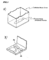
- FIGs 1A and 1B are diagrams showing an electromagnetic relay according to a first embodiment of the present invention and Fig. 1A is a perspective view of a molded resin cover 1 with its aperture portion faced upward and Fig. 1B is an expanded diagram showing portions 6 (6a, 6b) where laser-beam irradiation was performed.
- laser beam is applied surely from an inside of the molded resin cover 1, that is, from a face being opposite to a main body of the electromagnetic relay.
- Such a technology of applying laser beam is provided by, for example, Shinozaki Manufacturing Co., Ltd (Japan).
- Figure 5 is a cross-sectional view showing a relation between the diameter ⁇ A of the laser beam irradiated portion (laser beam coming-in side) and the diameter ⁇ B of the laser beam passing-through portion (laser beam going-out side) .
- t denotes a thickness of molded resin
- ⁇ denotes an angle related to focusing of the laser beam.
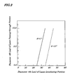
- Figure 2 is a graph showing a relation between the diameter ⁇ A of the laser-beam irradiated portion 6a and the diameter ⁇ B of the laser beam passing-through portion 6b.
- the thickness "t" is set to be 100 ⁇ m.
- the size ⁇ B of the laser beam passing-through portion 6b is calibrated so as to be equal to an air ventilating opening size of 1 ⁇ m to 10 ⁇ m.
- the laser-beam irradiated portions 6a are provided with pitches among central points of the irradiated portions each being longer than the diameter ⁇ A.
- the molded resin cover 1 of the embodiment employs uses, as its material, resins which have been generally used by known electromagnetic relays. These resins obtained after being molded have a large water contact angle and, therefore, have high resistance to water. Moreover, the employed molded resin cover 1 has high heat resistance and, as a result, even if a reflow heating process is performed under temperature conditions to be applied to lead-less soldering melting or a like, no change in shapes of the processed air ventilating openings occurs due to heat.
- a coating agent applicable to the embodiment it is preferable to select a coating agent having surface wettability to the molded resin cover 1 being equal or less than that of water, that is, having a contact angle of the coating agent to the molded resin cover 1 exceeding a contact angle of water to the molded resin cover 1.
- Figs. 3A and 3B are diagrams illustrating an electromagnetic relay according to a second embodiment of the present invention.
- Fig. 3A is a perspective view of a molded resin base 4 on which a main body of the electromagnetic relay is mounted and of portions 7 in which laser beam was applied
- Fig. 3B is an expanded perspective view of portions 7 in which laser beam was applied.
- laser beam is applied surely from an inside of a molded resin cover 1.
- one or more through-holes are formed by applying laser beam to desired positions of the molded resin base 4 from an inner surface side thereof, the desired positions which are not covered with a sealing resin 5 on an outer surface side thereof.
- the laser-beam irradiated portions 7a are provided with pitches among central points of the laser-beam irradiated portions each being longer than the diameter ⁇ A.
- the molded resin cover 1 of the embodiment employs, as its material, resins which have been generally used by known electromagnetic relays. These resins obtained after being molded have a large water contact angle, thus providing high resistance to water. Moreover, the employed molded resin base 4 has high heat resistance and, as a result, even if a reflow heating process is performed under temperature conditions to be applied to lead-less soldering melting or a like, no change in shapes of the processed air ventilating openings occurs due to heat.
- a coating agent applicable to the second embodiment shown in Figs. 3A and 3B it is preferable to select a coating agent having surface wettability to the molded resin cover 1 being equal or less than that of water, that is, having a contact angle of the coating agent to the molded resin base 4 exceeding a contact angle of water to the molded resin base 4.
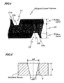
- Figure 4 is an expanded sectional view of a molded resin cover 1 made of a liquid crystal polymer 8 of the third embodiment which is applied to an electromagnetic relay shown in Figs. 6A and 6B . It is a characteristic of the liquid crystal polymer 8 that it becomes liquid crystal phase when being in a melted state.
- the molded resin cover 1 is of a three-layered structure including a first skin layer 9 with identical orientation of the liquid crystal formed on a surface side, a second skin layer 9 with identical orientation of the liquid crystal formed on a rear side, and a core layer 10 with random orientation of the liquid crystal formed between the first and second skin layers 9.
- the first and second skin layers 9 have identical orientation of the liquid crystal and ventilation is interrupted completely.
- the core layer 10 has air permeability due to its random orientation of the liquid crystal and also has a function as a filter.
- the diameters of laser-beam irradiated portions 11a and 12a are calibrated so that the hole size of each of laser beam passing-through portions 11b and 12b is 0.1 ⁇ m to 10 ⁇ m to form laser-beam applied portions 11 and 12.
- the laser beam passing-through portions 11b and 12b formed respectively on a surface and a rear of the molded resin cover 1 are not allowed to face each other and their positions are shifted so that the distances for ventilation in the core layer 10 serving as a filter can be secured at its maximum.
- Ventilation is obtained by the minute air ventilating openings formed on the surface and rear of the molded resin cover 1 made of the liquid crystal polymer 8 and by the filtering function of the core layer 10 serving the intermediate layer.
- Large water contact angle of the liquid crystal polymer 8 maintains high resistance to water.
- the liquid crystal polymer 8 has high heat-resistance enough to undergo lead-less soldering melting or a like, and no change in shapes of the processed air ventilating openings occurs due to heat.
- any coating agent can be used without limitation.
- the fourth embodiment is described by using Fig. 4 applied in the third embodiment. That is, in the fourth embodiment, a liquid crystal polymer 8 is used as a material for a molded resin base 4 shown in Figs. 6A and 6B . Shapes of air ventilating openings passing through only skin layers by laser beam irradiation are the same as obtained in the third embodiment. Moreover, the molded resin base 4 is coated with a sealing resin 5 from its bottom (outer surface) and laser beams are applied to portions not covered with the sealing resin 5. An electromagnetic relay of the fourth embodiment is assembled using the molded resin base 4 obtained as above and, as a result, the same effect as achieved in the third embodiment is realized. The use of the electromagnetic relay enables improved reliability of automatic parts or electrical components in particular. Besides, in other industrial fields, the present invention can be applied to an electromagnetic relay for application to measuring instruments and apparatus, which improves the reliability of contacting functions of contacts.
Landscapes
- Physics & Mathematics (AREA)
- Electromagnetism (AREA)
- Switch Cases, Indication, And Locking (AREA)
Abstract
Description
- The present invention relates to an electromagnetic relay and more particularly to the electromagnetic relay that can be suitably used as vehicle-mounted electrical components.
- A conventional electromagnetic relay having a switching function by opening and closing of electrical contacts and being used widely and commonly as a vehicle-mounted component includes electrical contacts and a molded resin material in which a molded resin base and an electromagnetic driving portion formed on the molded resin base are covered with a molded resin cover and is sealed with a thermosetting sealing resin. In the case where the electromagnetic relay is fully hermetically sealed from the outside, an escape path for air formed inside the relay is shut and, therefore, hermeticity occurs readily due to a thermal stress caused by reflow heating especially at an interface between a metal and a resin each having a different thermal expansion coefficient or in a bonding portion between a molded resin and a sealing resin. In the electromagnetic relay in which hermeticity has occurred, water, solvent, or a like invade from the outside, which causes an operational failure and a contacting failure of contact portions.
-
Figure 6 is an exploded perspective view of a conventional electromagnetic relay.Figures 7A and 7B are cross-sectional views explaining a structure of a conventional molded resin cover ofFigs. 6A and 6B , andFig. 7A is a vertical sectional view of a conventional unsealed- type of a through hole andFig. 7B is a vertical sectional view of a conventional sealed-type through-hole. In the conventional electromagnetic relay, as shown inFigs. 6A and 6B , an electromagnetic relaymain body 3 assembled on a moldedresin base 4 is covered with a moldedresin cover 1 and is sealed with a sealingresin 5 and through-holes 2 are formed on a top surface of the moldedresin cover 1. Conventionally, two types of the through-holes 2, one is an unsealed type of the through-hole in which an unsealed-type portion 2a shown inFig. 7A is not shut while a sealed-type portion 2b shown inFig. 7B is shut by fusing a top portion of the through-hole 2 and using a thermal caulking process at its top portion so that the electromagnetic relay is hermetically sealed. - If it is assumed that there is heat-stress caused by reflow heating on the electromagnetic relay, the above unsealed-type through-holes 2 (2a) are mainly used. However, in the case of the through-
holes 2 formed on the top of the moldedresin cover 1, since conditions for shapes and diameters are to be satisfied by considering moldability and workability of thermal caulking and since its aperture portion is wide, there is a risk that all kinds of substances on an outside of the electromagnetic relay invade easily into the electromagnetic relay. In particular, when the electromagnetic relay is used as a vehicle-mounted component by performing the reflow heating, in some cases, a coating agent is applied to all surfaces of the electromagnetic relay after being mounted on a printed circuit board and, in this case, the application of the coating agent to the through-holes 2 should be avoided. If the through-holes 2 are shut by the coating agent, the coating agent invades inside of the electromagnetic relay in some cases, causes an operational failure and/or contacting failure at contact portions. Moreover, a whole cleaning method in which the electromagnetic relay together with the printed circuit board are soaked should be also avoided. Thus, the unsealed through-holes 2 (2a) which do not provide a sealed state have a remarkably high risk and a limitation is imposed on the execution of unsealing method. - Conventional technology discloses a method of increasing hermeticity in the electromagnetic relay in which the
conventional sealing resin 5 is replaced with anew sealing resin 5 having high heat-resistance and a bonding characteristic being higher than those of the conventional moldedresin cover 1 and moldedresin base 4 as shown inFigs. 6A and 6B . - To solve the above problems, conventional technology is disclosed in Patent Reference 1 (
Japanese Patent Application Laid-open No. Hei 5-242784 Japanese Patent Application Laid-open No. Hei 11- 145667 - The above-disclosed technology to increase heat-resistance and/or bonding characteristic of the sealing
resin 5 are not sufficient to provide methods of improving bonding strength that can satisfy all conditions for diverse reflow heating. There is a limit point at which pressure inside the electromagnetic relay becomes high due to a high temperature and hermeticity failure occurs due to excessive thermal expansion. Therefore, cases are assumed where any one of the diverse conditions for the reflow heating exceeds the limit point at which hermeticity failure occurs. Moreover, the sealingresin 5 is vulnerable to changes by a coating condition, thermosetting condition, circumferential conditions such as an ambient temperature, humidity or a like and, therefore, its bonding characteristic is easy to change and it is impossible to keep its bonding strength constant in the manufacturing processes. As a result, the limit point causing the hermeticity failure changes. - Each of the technology to apply porous filters (the Patent Reference 1) and the technology to apply polymerized monomers to form air holes has problems (Patent Reference 2) in that it is difficult to establish the method of the applications. Moreover, the heat stress in the reflow heating causes it difficult to keep the air holes constantly porous. Additionally, new problems of an increase of component counts, increased costs caused by the increase of component counts, and increased number of man-hours arise.
- In view of the above, it is an object of the present invention to provide an electromagnetic relay which is capable of preventing an operational failure and a contacting failure at contact portions by maintaining air permeability and resistance to water (water invasion preventing property) even after being heated at a high temperature and by avoiding invasion of a coating agent. That is, the object of the present invention is to provide the electromagnetic relay which enables application of the coating agent even after being mounted on printed circuit boards having undergone reflow heating and water cleaning without causing an increase in component counts while maintaining air permeability and preventing the invasion of water.
- According to a first aspect of the present invention, there is provided an electromagnetic relay including:
- a main body including an electrical contact portion, an electromagnetic driving portion, and a molded resin base for mounting the electrical contact portion and the electromagnetic driving portion; wherein the main body is covered with a molded resin cover and is sealed with a sealing resin and wherein one or more through-holes are formed by applying laser beam to desired positions of the molded resin cover from an inner surface side thereof so that the through-holes each are within a size range in which no invasion of water from the outer side into the inner side thereof occurs and in which air permeability of the molded resin cover can be maintained through the through-holes.
- In a forgoing first aspect, a preferable mode is one wherein the through-holes each are set within spot diameter of 0.1µm to 10µm on an outer surface side of the molded resin cover as the size range.
- According to a second aspect of the present invention, there is provided an electromagnetic relay including:
- a main body including an electrical contact portion, an electromagnetic driving portion, and a molded resin base for mounting the electrical contact portion and the electromagnetic driving portion; wherein the main body is covered with a molded resin cover and is sealed with a sealing resin and wherein one or more through-holes are formed by applying laser beam to desired positions of the molded resin base from an inner surface side thereof, the desired positions which are not covered with the sealing resin on an outer surface side thereof so that the through-holes each are within a size range in which no invasion of water from the outer side into the inner side thereof occurs and in which air permeability of the molded resin base can be maintained through the through-holes.
- In a foregoing second aspect, a preferable mode is one the through-holes each are set within spot diameter of 0.1µm to 10µm on an outer surface side of the molded resin base as the size range.
- According to a third aspect of the present invention, there is provided an electromagnetic relay including:
- a main body including an electrical contact portion, an electromagnetic driving portion, and a molded resin base for mounting the electrical contact portion and the electromagnetic driving portion; wherein the main body is covered with a molded resin cover and is sealed with a sealing resin and wherein the molded resin cover comprises a liquid crystal polymer having skin layers with identical orientation formed on both sides of a core layer in an intermediate position between the skin layers and wherein laser beams are applied to desired positions of the molded resin cover from both inner and outer sides thereof so that the laser beam passes through only the skin layers with the core layer being left unprocessed by the laser beams to form one or more through-holes on each of the skin layers which each are within a size range in which no invasion of water from the outer side into the inner side thereof occurs and in which air permeability of the molded resin cover can be maintained through the through-holes.
- In a foregoing third aspect, a preferable mode is one the through-holes each are set within spot diameter of 0.1µm to 10µm on an outer surface side of the molded resin cover as the size range.
- According to a fourth aspect of the present invention, there is provided an electromagnetic relay including:
- a main body including an electrical contact portion, an electromagnetic driving portion, and a molded resin base for mounting the electrical contact portion and the electromagnetic driving portion; wherein the main body is covered with a molded resin cover and is sealed with a sealing resin and wherein the molded resin cover comprises a liquid crystal polymer having skin layers with identical orientation formed on both sides of a core layer in an intermediate position between the skin layers and wherein laser beams are applied to desired positions of the molded resin base from both inner and outer sides thereof, the desired positions which are not covered with the sealing resin on an outer surface side thereof, so that the laser beams pass through only the skin layers with the core layer being left unprocessed by the laser beams to form one or more through-holes on each of the skin layers which each are within a size range in which no invasion of water from the outer side into the inner side thereof occurs and in which air permeability of the molded resin base can be maintained through the through-holes.
- In a foregoing fourth aspect, a preferable mode is one the through-holes each are set within spot diameter of 0,1µm to 10µm on an outer surface side of the molded resin base as the size range.
- With the above configuration, it is made possible to provide the electromagnetic relay having both air permeability and resistance to water, which enables the coating process with the coating agent even after being mounted on the printed circuit board having undergone reflow heating and also which enables a water-cleaning process, thereby eliminating an operational failure and contacting failure at contact portions. That is, the electromagnetic relay of the present invention has a method of forming stable air ventilating openings (air holes) on the molded resin even after being heated at high temperature, which ensures only high air permeability and resistance to water (water invasion preventing property) of the electromagnetic relay. The size of each of the air ventilating openings is fine and its shape and dimension can be fully controlled and, as a result, it is possible to achieve high resistance to water while controlling air permeability. Additionally, it is made possible to avoid invasion of the coating agent, thereby preventing the operational failure and contacting failure at contact portions.
- The above and other objects, advantages, and features of the present invention will be more apparent from the following description taken in conjunction with the accompanying drawings in which:
-
Figs. 1A and 1B are diagrams showing an electromagnetic relay according to a first embodiment of the present invention, andFig. 1A is a perspective view of a molded resin cover with an aperture portion faced upward andFig. 1B is an expanded diagram showing portions where laser beam irradiation was performed; -
Fig. 2 is a graph illustrating a relation between a diameter ⌀A of a laser-beam irradiated portion and a diameter ⌀B of a laser beam passing-through portion; -
Figs. 3A and 3B are diagrams illustrating an electromagnetic relay according to a second embodiment of the present invention, andFig. 3A is a perspective view of a molded resin base on which a main body of the electromagnetic relay is mounted andFig. 3B is an expanded perspective view of a portion in which laser beam was applied; -
Fig. 4 is an expanded sectional view of a molded resin cover applied to an electromagnetic relay according to a third embodiment; -
Fig. 5 is a cross-sectional view showing a relation between the diameter ø A of a laser-beam irradiated portion and the diameter ⌀B of a laser beam passing-through portion according to the first embodiment; -
Figs. 6A and 6B are perspective views showing a conventional electromagnetic relay, andFig. 6A is an exploded perspective view of the conventional electromagnetic relay andFig. 6B is a partially cutaway perspective view showing the conventional electromagnetic relay; and -
Figs. 7A and 7B are cross-sectional views explaining a conventional structure of a molded resin cover ofFigs. 6A and 6B , andFig. 7A is a vertical sectional view of a conventional unsealed- type of a through hole andFig. 7B is a vertical sectional view of a conventional sealed-type through-hole. - Best modes of carrying out the present invention will be described in further detail using various embodiments with reference to the accompanying drawings. According to embodiments of the present invention, when air ventilating openings are formed by laser beam irradiation, a diameter of each air ventilating opening falls within a range of 0.1µm to 10µm. The diameter of each air ventilating opening is a size of an exit portion through which laser beam passes on a surface of a molded resin making up the electromagnetic relay. The size of the laser-beam irradiating portion is changed to calibrate a diameter of the exit portion that allows laser beam to pass through. The size of each hole of 0.1µm to 10µm is a size range in which no invasion of water into an inside of the electromagnetic relay occurs and in which air permeability can be maintained when water is in contact with the surface of the molded resin and when a water contact angle to the molded resin to be used for the electromagnetic relays is taken into consideration in general. Moreover, resistance to water can be adjusted within the above size range.
- Any one of excimer laser, CO2 laser, or YAG laser may be applied to the above processing. In some cases, a through-hole cannot be formed by one-time laser beam irradiation depending on a thickness of the molded resin. In this case, the through-hole can be formed by applying laser beam a plurality of times to the same spot.
-
Figures 1A and 1B are diagrams showing an electromagnetic relay according to a first embodiment of the present invention andFig. 1A is a perspective view of a moldedresin cover 1 with its aperture portion faced upward andFig. 1B is an expanded diagram showing portions 6 (6a, 6b) where laser-beam irradiation was performed. In the first embodiment, laser beam is applied surely from an inside of the moldedresin cover 1, that is, from a face being opposite to a main body of the electromagnetic relay. Such a technology of applying laser beam is provided by, for example, Shinozaki Manufacturing Co., Ltd (Japan). In an example of forming a shape like this, a relation of a diameter ⌀A of the laser-beamirradiated portion 6a and a diameter ⌀ B of the laser-beamirradiated portion 6b is shown by an equation ØA-2sinθ•t=ØB.Figure 5 is a cross-sectional view showing a relation between the diameter ⌀A of the laser beam irradiated portion (laser beam coming-in side) and the diameter ⌀B of the laser beam passing-through portion (laser beam going-out side) . In the above equation, "t" denotes a thickness of molded resin and "θ" denotes an angle related to focusing of the laser beam. In the case of CO2 laser, θ=7° to 10°.Figure 2 is a graph showing a relation between the diameter ⌀A of the laser-beamirradiated portion 6a and the diameter ⌀B of the laser beam passing-throughportion 6b. The thickness "t" is set to be 100µm. Based on the relation described above, the size ⌀B of the laser beam passing-throughportion 6b is calibrated so as to be equal to an air ventilating opening size of 1µm to 10µm. - When a plurality of laser-beam irradiated portions each having a structure shown in
Fig. 1B is to be formed, the laser-beamirradiated portions 6a are provided with pitches among central points of the irradiated portions each being longer than the diameter ⌀A. - By carrying out the first embodiment as above, ventilation is obtained through minute air ventilating openings formed on a surface of the molded
resin cover 1. The moldedresin cover 1 of the embodiment employs uses, as its material, resins which have been generally used by known electromagnetic relays. These resins obtained after being molded have a large water contact angle and, therefore, have high resistance to water. Moreover, the employed moldedresin cover 1 has high heat resistance and, as a result, even if a reflow heating process is performed under temperature conditions to be applied to lead-less soldering melting or a like, no change in shapes of the processed air ventilating openings occurs due to heat. - Furthermore, regarding a coating agent applicable to the embodiment, it is preferable to select a coating agent having surface wettability to the molded
resin cover 1 being equal or less than that of water, that is, having a contact angle of the coating agent to the moldedresin cover 1 exceeding a contact angle of water to the moldedresin cover 1. -
Figs. 3A and 3B are diagrams illustrating an electromagnetic relay according to a second embodiment of the present invention; andFig. 3A is a perspective view of a moldedresin base 4 on which a main body of the electromagnetic relay is mounted and ofportions 7 in which laser beam was applied andFig. 3B is an expanded perspective view ofportions 7 in which laser beam was applied. In the first embodiment, laser beam is applied surely from an inside of a moldedresin cover 1. Instead the configuration of the first embodiment, in the second embodiment, one or more through-holes are formed by applying laser beam to desired positions of the moldedresin base 4 from an inner surface side thereof, the desired positions which are not covered with a sealingresin 5 on an outer surface side thereof. - When a plurality of laser-beam irradiated portions 7 (7a, 7b) each having a structure shown in
Fig. 3B is to be formed, the laser-beamirradiated portions 7a are provided with pitches among central points of the laser-beam irradiated portions each being longer than the diameter ⌀A. - By carrying out the second embodiment as shown in
Figs. 3A and 3B , ventilation is obtained through minute air ventilating openings formed on a surface of the moldedresin cover 4. The moldedresin cover 1 of the embodiment employs, as its material, resins which have been generally used by known electromagnetic relays. These resins obtained after being molded have a large water contact angle, thus providing high resistance to water. Moreover, the employed moldedresin base 4 has high heat resistance and, as a result, even if a reflow heating process is performed under temperature conditions to be applied to lead-less soldering melting or a like, no change in shapes of the processed air ventilating openings occurs due to heat. - Furthermore, regarding a coating agent applicable to the second embodiment shown in
Figs. 3A and 3B , it is preferable to select a coating agent having surface wettability to the moldedresin cover 1 being equal or less than that of water, that is, having a contact angle of the coating agent to the moldedresin base 4 exceeding a contact angle of water to the moldedresin base 4. -
Figure 4 is an expanded sectional view of a moldedresin cover 1 made of aliquid crystal polymer 8 of the third embodiment which is applied to an electromagnetic relay shown inFigs. 6A and 6B . It is a characteristic of theliquid crystal polymer 8 that it becomes liquid crystal phase when being in a melted state. As shown inFig. 4 , the moldedresin cover 1 is of a three-layered structure including afirst skin layer 9 with identical orientation of the liquid crystal formed on a surface side, asecond skin layer 9 with identical orientation of the liquid crystal formed on a rear side, and acore layer 10 with random orientation of the liquid crystal formed between the first and second skin layers 9. When air ventilating openings are formed by laser beam irradiation, laser beam is not allowed fully to pass through theliquid crystal polymer 8 and allowed to pass through only the first and second skin layers 9. The first andsecond skin layers 9 have identical orientation of the liquid crystal and ventilation is interrupted completely. Thecore layer 10 has air permeability due to its random orientation of the liquid crystal and also has a function as a filter. - When laser beam is applied to the skin layers 9, by taking the relation between a diameter ⌀A of a laser-beam
irradiated portion 6a and a diameter ⌀B of a laser-beamirradiated portion 6b shown in the first embodiment into consideration, the diameters of laser-beamirradiated portions 11a and 12a are calibrated so that the hole size of each of laser beam passing-throughportions portions portions resin cover 1 are not allowed to face each other and their positions are shifted so that the distances for ventilation in thecore layer 10 serving as a filter can be secured at its maximum. - Thus, in the third embodiment in
Fig. 4 , ventilation is obtained by the minute air ventilating openings formed on the surface and rear of the moldedresin cover 1 made of theliquid crystal polymer 8 and by the filtering function of thecore layer 10 serving the intermediate layer. Large water contact angle of theliquid crystal polymer 8 maintains high resistance to water. Moreover, theliquid crystal polymer 8 has high heat-resistance enough to undergo lead-less soldering melting or a like, and no change in shapes of the processed air ventilating openings occurs due to heat. - Also, in the third embodiment shown in
Fig. 4 , since thecore layer 10 existing in the intermediate position of each of the air ventilating openings functions as the filter, any coating agent can be used without limitation. - The fourth embodiment is described by using
Fig. 4 applied in the third embodiment. That is, in the fourth embodiment, aliquid crystal polymer 8 is used as a material for a moldedresin base 4 shown inFigs. 6A and 6B . Shapes of air ventilating openings passing through only skin layers by laser beam irradiation are the same as obtained in the third embodiment. Moreover, the moldedresin base 4 is coated with a sealingresin 5 from its bottom (outer surface) and laser beams are applied to portions not covered with the sealingresin 5. An electromagnetic relay of the fourth embodiment is assembled using the moldedresin base 4 obtained as above and, as a result, the same effect as achieved in the third embodiment is realized. The use of the electromagnetic relay enables improved reliability of automatic parts or electrical components in particular. Besides, in other industrial fields, the present invention can be applied to an electromagnetic relay for application to measuring instruments and apparatus, which improves the reliability of contacting functions of contacts. - It is apparent that the present invention is not limited to the above embodiments but may be changed and modified without departing from the scope and spirit of the invention.
Claims (8)
- An electromagnetic relay comprising: a main body (3) comprising an electrical contact portion, an electromagnetic driving portion, and a molded resin base (4) for mounting said electrical contact portion and said electromagnetic driving portion,
the electromagnetic relay characterized in that said main body (3) is covered with a molded resin cover (1) and is sealed with a sealing resin (5), and
that one or more through-holes (6) are formed by applying laser beam to desired positions of said molded resin cover (1) from an inner surface side thereof so that said through-holes (6) each are within a size range in which no invasion of water from the outer side into the inner side thereof occurs and in which air permeability of said molded resin cover (1) can be maintained through said through-holes (6). - The electromagnetic relay according to claim 1, characterized in that said through-holes (6) each are set within spot diameter of 0.1µm to 10µm on an outer surface side of said molded resin cover (1) as the size range.
- An electromagnetic relay comprising: a main body (3) comprising an electrical contact portion, an electromagnetic driving portion, and a molded resin base (4) for mounting said electrical contact portion and said electromagnetic driving portion,
the electromagnetic relay characterized in that said main body (3) is covered with a molded resin cover (1) and is sealed with a sealing resin (5), and
that one or more through-holes (6) are formed by applying laser beam to desired positions of said molded resin base (4) from an inner surface side thereof, the desired positions which are not covered with said sealing resin (5) on an outer surface side thereof so that said through-holes (6) each are within a size range in which no invasion of water from the outer side into the inner side thereof occurs and in which air permeability of said molded resin base (4) can be maintained through said through-holes (6). - The electromagnetic relay according to claim 3, characterized in that said through-holes (6) each are set within spot diameter of 0.1µm to 10µm on an outer surface side of said molded resin base (4) as the size range.
- An electromagnetic relay comprising: a main body (3) comprising an electrical contact portion, an electromagnetic driving portion, and a molded resin base (4) for mounting said electrical contact portion and said electromagnetic driving portion,
the electromagnetic relay characterized in that said main body (3) is covered with a molded resin cover (1) and is sealed with a sealing resin (5), and
that said molded resin cover (1) comprises a liquid crystal polymer (8) having skin layers (9) with identical orientation formed on both sides of a core layer (10) in an intermediate position between said skin layers (9), and
that laser beams are applied to desired positions of said molded resin cover (1) from both inner and outer sides thereof so that the laser beam passes through only said skin layers (9) with said core layer (10) being left unprocessed by the laser beams to form one or more through-holes (6) on each of said skin layers (9) which each are within a size range in which no invasion of water from the outer side into the inner side thereof occurs and in which air permeability of said molded resin cover (1) can be maintained through said through-holes (6). - The electromagnetic relay according to claim 5, characterized in that said through-holes (6) each are set within spot diameter of 0.1µm to 10µm on an outer surface side of said molded resin cover (1) as the size range.
- An electromagnetic relay comprising a main body (3) comprising an electrical contact portion, an electromagnetic driving portion, and a molded resin base (4) for mounting said electrical contact portion and said electromagnetic driving portion,
the electromagnetic relay characterized in that;
said main body (3) is covered with a molded resin cover (1) and is sealed with a sealing resin (5),
that said molded resin cover (1) comprises a liquid crystal polymer (8) having skin layers (9) with identical orientation formed on both sides of a core layer (9) in an intermediate position between said skin layers (9), and
that laser beams are applied to desired positions of said molded resin base (4) from both inner and outer sides thereof, the desired positions which are not covered with said sealing resin (5) on an outer surface side thereof, so that the laser beams pass through only said skin layers (9) with said core layer (10) being left unprocessed by the laser beams to form one or more through-holes (6) on each of said skin layers (9) which each are within a size range in which no invasion of water from the outer side into the inner side thereof occurs and in which air permeability of said molded resin base (4) can be maintained through said through-holes (6). - The electromagnetic relay according to claim 7, the electromagnetic relay characterized in that said through-holes (6) each are set within spot diameter of 0.1µm to 10µm on an outer surface side of said molded resin base (4) as the size range.
Priority Applications (2)
| Application Number | Priority Date | Filing Date | Title |
|---|---|---|---|
| DE200760008047 DE602007008047D1 (en) | 2007-01-31 | 2007-01-31 | Electromagnetic relay |
| EP20070002134 EP1953783B1 (en) | 2007-01-31 | 2007-01-31 | Electromagnetic relay |
Applications Claiming Priority (1)
| Application Number | Priority Date | Filing Date | Title |
|---|---|---|---|
| EP20070002134 EP1953783B1 (en) | 2007-01-31 | 2007-01-31 | Electromagnetic relay |
Publications (2)
| Publication Number | Publication Date |
|---|---|
| EP1953783A1 true EP1953783A1 (en) | 2008-08-06 |
| EP1953783B1 EP1953783B1 (en) | 2010-07-28 |
Family
ID=38121315
Family Applications (1)
| Application Number | Title | Priority Date | Filing Date |
|---|---|---|---|
| EP20070002134 Active EP1953783B1 (en) | 2007-01-31 | 2007-01-31 | Electromagnetic relay |
Country Status (2)
| Country | Link |
|---|---|
| EP (1) | EP1953783B1 (en) |
| DE (1) | DE602007008047D1 (en) |
Cited By (1)
| Publication number | Priority date | Publication date | Assignee | Title |
|---|---|---|---|---|
| CN113284766A (en) * | 2021-07-19 | 2021-08-20 | 深圳市森皓伟业制冷设备有限公司 | Relay |
Citations (5)
| Publication number | Priority date | Publication date | Assignee | Title |
|---|---|---|---|---|
| GB2029107A (en) * | 1978-08-17 | 1980-03-12 | Bosch Gmbh Robert | Electro-magnetic relay |
| US4427863A (en) | 1982-03-22 | 1984-01-24 | Izumi Denki Corporation | Small-sized relay and method for fabricating the same |
| EP0986290A2 (en) * | 1998-09-07 | 2000-03-15 | DaimlerChrysler AG | Method for manufacturing a moisture impermeable element for pressure compensation in housing |
| EP1026716A1 (en) * | 1999-02-04 | 2000-08-09 | Chauvin Arnoux | Electromagnetic relay with enclosing cover |
| EP1091236A2 (en) * | 1999-10-05 | 2001-04-11 | Matsushita Electric Industrial Co., Ltd. | Liquid crystal display |
-
2007
- 2007-01-31 DE DE200760008047 patent/DE602007008047D1/en active Active
- 2007-01-31 EP EP20070002134 patent/EP1953783B1/en active Active
Patent Citations (5)
| Publication number | Priority date | Publication date | Assignee | Title |
|---|---|---|---|---|
| GB2029107A (en) * | 1978-08-17 | 1980-03-12 | Bosch Gmbh Robert | Electro-magnetic relay |
| US4427863A (en) | 1982-03-22 | 1984-01-24 | Izumi Denki Corporation | Small-sized relay and method for fabricating the same |
| EP0986290A2 (en) * | 1998-09-07 | 2000-03-15 | DaimlerChrysler AG | Method for manufacturing a moisture impermeable element for pressure compensation in housing |
| EP1026716A1 (en) * | 1999-02-04 | 2000-08-09 | Chauvin Arnoux | Electromagnetic relay with enclosing cover |
| EP1091236A2 (en) * | 1999-10-05 | 2001-04-11 | Matsushita Electric Industrial Co., Ltd. | Liquid crystal display |
Cited By (1)
| Publication number | Priority date | Publication date | Assignee | Title |
|---|---|---|---|---|
| CN113284766A (en) * | 2021-07-19 | 2021-08-20 | 深圳市森皓伟业制冷设备有限公司 | Relay |
Also Published As
| Publication number | Publication date |
|---|---|
| DE602007008047D1 (en) | 2010-09-09 |
| EP1953783B1 (en) | 2010-07-28 |
Similar Documents
| Publication | Publication Date | Title |
|---|---|---|
| US7538645B2 (en) | Electromagnetic relay | |
| CN101937813B (en) | Subminiature fuse with surface mount end caps and improved connectivity | |
| US7377795B2 (en) | Electrical contacts having solder stops | |
| US8740043B2 (en) | Selective solder stop | |
| JP5080653B2 (en) | Method for contacting rigid printed circuit board with contact partner and apparatus comprising rigid printed circuit board and contact partner | |
| JPH11176308A (en) | Method of manufacturing fuse element and fuse element | |
| US5923239A (en) | Printed circuit board assembly having an integrated fusible link | |
| KR20100101560A (en) | Manufacturability of smd and through-hole fuses using laser process | |
| EP1953783B1 (en) | Electromagnetic relay | |
| US20070193991A1 (en) | Method of soldering wiring members by laser beam irradiation | |
| JP4540064B2 (en) | Electromagnetic relay | |
| EP3282467B1 (en) | Fuse production method, fuse, circuit board production method and circuit board | |
| WO2012005024A1 (en) | Surface-mounted electronic component | |
| CN101236862B (en) | Electromagnetic relay | |
| US20060196857A1 (en) | Methods of manufacturing electrical contacts having solder stops | |
| JP2006284991A (en) | Lens unit | |
| EP4002411A1 (en) | Electronic component and method for manufacturing same | |
| JP2009076364A (en) | Electromagnetic relay | |
| JP5597193B2 (en) | Sensor with cover and method for manufacturing the same | |
| US12154740B2 (en) | Electronic component | |
| JPH07183632A (en) | Printed wiring board and its assembly method | |
| US12424402B2 (en) | Electric device comprising a sealed housing having a lower housing part and an upper housing part | |
| JP4453447B2 (en) | Solid-state image pickup device storage package and method for manufacturing solid-state image pickup device storage package | |
| JP2011003287A (en) | Electromagnetic relay | |
| JP2005243468A5 (en) |
Legal Events
| Date | Code | Title | Description |
|---|---|---|---|
| PUAI | Public reference made under article 153(3) epc to a published international application that has entered the european phase |
Free format text: ORIGINAL CODE: 0009012 |
|
| AK | Designated contracting states |
Kind code of ref document: A1 Designated state(s): AT BE BG CH CY CZ DE DK EE ES FI FR GB GR HU IE IS IT LI LT LU LV MC NL PL PT RO SE SI SK TR |
|
| AX | Request for extension of the european patent |
Extension state: AL BA HR MK RS |
|
| 17P | Request for examination filed |
Effective date: 20080708 |
|
| 17Q | First examination report despatched |
Effective date: 20090203 |
|
| AKX | Designation fees paid |
Designated state(s): DE |
|
| GRAP | Despatch of communication of intention to grant a patent |
Free format text: ORIGINAL CODE: EPIDOSNIGR1 |
|
| GRAS | Grant fee paid |
Free format text: ORIGINAL CODE: EPIDOSNIGR3 |
|
| GRAA | (expected) grant |
Free format text: ORIGINAL CODE: 0009210 |
|
| AK | Designated contracting states |
Kind code of ref document: B1 Designated state(s): DE |
|
| REF | Corresponds to: |
Ref document number: 602007008047 Country of ref document: DE Date of ref document: 20100909 Kind code of ref document: P |
|
| PLBE | No opposition filed within time limit |
Free format text: ORIGINAL CODE: 0009261 |
|
| STAA | Information on the status of an ep patent application or granted ep patent |
Free format text: STATUS: NO OPPOSITION FILED WITHIN TIME LIMIT |
|
| 26N | No opposition filed |
Effective date: 20110429 |
|
| REG | Reference to a national code |
Ref country code: DE Ref legal event code: R097 Ref document number: 602007008047 Country of ref document: DE Effective date: 20110429 |
|
| REG | Reference to a national code |
Ref country code: DE Ref legal event code: R082 Ref document number: 602007008047 Country of ref document: DE Representative=s name: GLAWE DELFS MOLL PARTNERSCHAFT MBB VON PATENT-, DE Ref country code: DE Ref legal event code: R081 Ref document number: 602007008047 Country of ref document: DE Owner name: EM DEVICES CORP., SHIROISHI-SHI, JP Free format text: FORMER OWNER: NEC TOKIN CORP., SENDAI, MIYAGI, JP |
|
| REG | Reference to a national code |
Ref country code: DE Ref legal event code: R082 Ref document number: 602007008047 Country of ref document: DE Representative=s name: GLAWE DELFS MOLL PARTNERSCHAFT MBB VON PATENT-, DE Ref country code: DE Ref legal event code: R082 Ref document number: 602007008047 Country of ref document: DE Representative=s name: GLAWE DELFS MOLL PARTGMBB, DE |
|
| PGFP | Annual fee paid to national office [announced via postgrant information from national office to epo] |
Ref country code: DE Payment date: 20251210 Year of fee payment: 20 |