EP1953602A1 - Developing apparatus, process cartridge and image forming apparatus - Google Patents
Developing apparatus, process cartridge and image forming apparatus Download PDFInfo
- Publication number
- EP1953602A1 EP1953602A1 EP07122811A EP07122811A EP1953602A1 EP 1953602 A1 EP1953602 A1 EP 1953602A1 EP 07122811 A EP07122811 A EP 07122811A EP 07122811 A EP07122811 A EP 07122811A EP 1953602 A1 EP1953602 A1 EP 1953602A1
- Authority
- EP
- European Patent Office
- Prior art keywords
- developer
- toner
- accommodating chamber
- chamber
- stirring member
- Prior art date
- Legal status (The legal status is an assumption and is not a legal conclusion. Google has not performed a legal analysis and makes no representation as to the accuracy of the status listed.)
- Granted
Links
Images












Classifications
-
- G—PHYSICS
- G03—PHOTOGRAPHY; CINEMATOGRAPHY; ANALOGOUS TECHNIQUES USING WAVES OTHER THAN OPTICAL WAVES; ELECTROGRAPHY; HOLOGRAPHY
- G03G—ELECTROGRAPHY; ELECTROPHOTOGRAPHY; MAGNETOGRAPHY
- G03G15/00—Apparatus for electrographic processes using a charge pattern
- G03G15/06—Apparatus for electrographic processes using a charge pattern for developing
- G03G15/08—Apparatus for electrographic processes using a charge pattern for developing using a solid developer, e.g. powder developer
- G03G15/0822—Arrangements for preparing, mixing, supplying or dispensing developer
- G03G15/0848—Arrangements for testing or measuring developer properties or quality, e.g. charge, size, flowability
- G03G15/0856—Detection or control means for the developer level
-
- G—PHYSICS
- G03—PHOTOGRAPHY; CINEMATOGRAPHY; ANALOGOUS TECHNIQUES USING WAVES OTHER THAN OPTICAL WAVES; ELECTROGRAPHY; HOLOGRAPHY
- G03G—ELECTROGRAPHY; ELECTROPHOTOGRAPHY; MAGNETOGRAPHY
- G03G15/00—Apparatus for electrographic processes using a charge pattern
- G03G15/06—Apparatus for electrographic processes using a charge pattern for developing
- G03G15/08—Apparatus for electrographic processes using a charge pattern for developing using a solid developer, e.g. powder developer
- G03G15/0822—Arrangements for preparing, mixing, supplying or dispensing developer
- G03G15/0848—Arrangements for testing or measuring developer properties or quality, e.g. charge, size, flowability
- G03G15/0856—Detection or control means for the developer level
- G03G15/0862—Detection or control means for the developer level the level being measured by optical means
-
- G—PHYSICS
- G03—PHOTOGRAPHY; CINEMATOGRAPHY; ANALOGOUS TECHNIQUES USING WAVES OTHER THAN OPTICAL WAVES; ELECTROGRAPHY; HOLOGRAPHY
- G03G—ELECTROGRAPHY; ELECTROPHOTOGRAPHY; MAGNETOGRAPHY
- G03G15/00—Apparatus for electrographic processes using a charge pattern
- G03G15/06—Apparatus for electrographic processes using a charge pattern for developing
- G03G15/08—Apparatus for electrographic processes using a charge pattern for developing using a solid developer, e.g. powder developer
- G03G15/0822—Arrangements for preparing, mixing, supplying or dispensing developer
- G03G15/0887—Arrangements for conveying and conditioning developer in the developing unit, e.g. agitating, removing impurities or humidity
- G03G15/0889—Arrangements for conveying and conditioning developer in the developing unit, e.g. agitating, removing impurities or humidity for agitation or stirring
-
- G—PHYSICS
- G03—PHOTOGRAPHY; CINEMATOGRAPHY; ANALOGOUS TECHNIQUES USING WAVES OTHER THAN OPTICAL WAVES; ELECTROGRAPHY; HOLOGRAPHY
- G03G—ELECTROGRAPHY; ELECTROPHOTOGRAPHY; MAGNETOGRAPHY
- G03G2215/00—Apparatus for electrophotographic processes
- G03G2215/01—Apparatus for electrophotographic processes for producing multicoloured copies
- G03G2215/0103—Plural electrographic recording members
- G03G2215/0119—Linear arrangement adjacent plural transfer points
- G03G2215/0122—Linear arrangement adjacent plural transfer points primary transfer to an intermediate transfer belt
- G03G2215/0125—Linear arrangement adjacent plural transfer points primary transfer to an intermediate transfer belt the linear arrangement being horizontal or slanted
- G03G2215/0132—Linear arrangement adjacent plural transfer points primary transfer to an intermediate transfer belt the linear arrangement being horizontal or slanted vertical medium transport path at the secondary transfer
-
- G—PHYSICS
- G03—PHOTOGRAPHY; CINEMATOGRAPHY; ANALOGOUS TECHNIQUES USING WAVES OTHER THAN OPTICAL WAVES; ELECTROGRAPHY; HOLOGRAPHY
- G03G—ELECTROGRAPHY; ELECTROPHOTOGRAPHY; MAGNETOGRAPHY
- G03G2215/00—Apparatus for electrophotographic processes
- G03G2215/08—Details of powder developing device not concerning the development directly
- G03G2215/0802—Arrangements for agitating or circulating developer material
-
- G—PHYSICS
- G03—PHOTOGRAPHY; CINEMATOGRAPHY; ANALOGOUS TECHNIQUES USING WAVES OTHER THAN OPTICAL WAVES; ELECTROGRAPHY; HOLOGRAPHY
- G03G—ELECTROGRAPHY; ELECTROPHOTOGRAPHY; MAGNETOGRAPHY
- G03G2215/00—Apparatus for electrophotographic processes
- G03G2215/08—Details of powder developing device not concerning the development directly
- G03G2215/0888—Arrangements for detecting toner level or concentration in the developing device
- G03G2215/0891—Optical detection
- G03G2215/0894—Optical detection through a light transmissive window in the developer container wall
- G03G2215/0897—Cleaning of the light transmissive window
Definitions
- the present invention relates to an electrophotographic image forming apparatus, a developing apparatus employed by an electrophotographic image forming apparatus, and a process cartridge removably mountable in an electrophotographic image forming apparatus.
- an "electrophotographic image forming apparatus” means an apparatus which forms an image on recording medium, using an electrophotographic image forming method.
- Examples of an electrophotographic image forming apparatus include an electrophotographic copying machine, an electrophotographic printer (laser beam printer, LED printer, etc.), a facsimile apparatus, a wordprocessor, and a multifunction apparatus capable of performing two or more functions of the preceding apparatuses, etc.
- a “developing apparatus” means an apparatus which develops an electrostatic latent image on an image bearing member, such as an electrophotographic photosensitive drum, into a visible image, with the use of developer.
- the process cartridge means a cartridge in which at least a developing means and an electrophotographic photosensitive drum, are integrally disposed so that they can be removably mountable in the main assembly of an electrophotographic image forming apparatus.
- an image forming apparatus such as a copying machine, a printer, or a facsimile machine, forms an electrostatic latent image on an image bearing member, such as an electrophotographic photosensitive member, and develops the electrostatic latent image into a visible image, more specifically, a visible image formed of toner, with the use of a developing apparatus.
- a process cartridge system has long been in use, according to which an electrophotographic photosensitive member, and one or more process cartridges which act on the electrophotographic photosensitive member, are integrally disposed in a cartridge removably mountable in the main assembly of an image forming apparatus.
- a process cartridge system makes it possible for a user to maintain an electrophotographic image forming apparatus without relying on a service person. Therefore, it can drastically improve an electrophotographic image forming apparatus, in terms of operability.
- process cartridge replacement is developer (toner) depletion.
- developer toner
- some of recent electrophotographic image forming apparatuses are designed so that they detect the amount of the toner remaining in a process cartridge. There are various methods usable for detecting the amount of toner remainder.
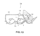
- a beam of light for detecting the amount of the toner remainder (which hereafter may be referred to simply as detection light), which is emitted from a light emitting portion, such as an LED, attached to the main assembly of an image forming apparatus, is guided through a light guide (unshown) attached to the image forming apparatus or the toner container 141 of a process cartridge, and then, into the toner container 141 through a transparent window 173 of the toner container 141.
- the toner container 141 is structured so that as the detection light L enters the toner container 141, it comes out, or fails to come out, of the toner container 141 through another transparent window or the like. It depends on various factors such as the amount of toner in the toner container 141 whether or not the detection beam L comes out of the toner container 141. As the detection light L of comes out of the light exit window, it is guided to a light receiving portion (unshown), such as a phototransistor, by a light guide (unshown), such as the abovementioned light guide, attached to the main assembly of the image forming apparatus, or the toner container 141. The light receiving portion is attached to the main assembly of the image forming apparatus, or the like.
- the stirring members 171 and 172 are for conveying the toner in the toner container toward a development roller 140 while stirring the toner.
- the detection light L enters the toner container 141 while the stirring member 171 and 172 are rotated, it is blocked by the stirring members 171 and 172 and/or the toner.
- the smaller the amount of toner in the toner container 141 the longer the length of time the detection light L is allowed to transmit through the toner container 141.
- the amount of toner (toner remainder) in the toner container 141 can be estimated by measuring the length of time the detection light L is allowed to transmit through the toner container 141.
- This method of detecting (estimating) the amount of the toner remainder in the toner container 141 is referred to as a toner remainder amount detecting method of the light transmission type.
- the present invention is the further development of the prior art described above.
- the amount of the light received by the light receiving portion is expressed in the form of a graph, the vertical and horizontal axes of which represent the amount of the light received and the length of elapsed time, respectively, the amount of the light received by the light receiving portion changes as shown in Figure 23 ; a waveform shown in Figure 23 is obtained.
- the control portion of the main assembly of the image forming apparatus receives, from the light receiving portion, the electric signals which correspond to the amount of the light received by the light receiving portion, it measures the length of the periods a1, a2, a3, ... of time, in which the amount of the received light is no less than a preset value (threshold value). Then, based on the measured length of the periods of time, the control portion calculates (estimates) the amount of the toner remainder in the toner container 141.
- the pattern of the changes in the amount of the light received by the light receiving portion which is expressed in the waveform in Figure 23 , is affected by the shape of the toner container 141, the positional relationship between the transparent windows 173 and 174 and stirring members 171 and 172, etc. Therefore, the amount of the light which the light receiving portion receives does not always change in the same pattern (waveform).
- the threshold value is set shown in Figure 23 , the periods a1, a2, a3, ... become different in length, affecting thereby the accuracy with which the amount of the toner remainder in the toner container 141 can be detected.
- the primary object of the present invention is to provide a developing apparatus, a process cartridge, and an electrophotographic image forming apparatus, the amount of the developer remainder in which can be precisely detected.
- a developing apparatus for use with an electrophotographic image forming apparatus, said developing device comprising a developer accommodating chamber for accommodating a developer; a developer chamber including the developer carrying member for carrying and feeding a developer supplied from said developer accommodating chamber to develop an electrostatic latent image formed on an electrophotographic photosensitive member; a developer stirring member, rotatably provided in said developer accommodating chamber, for stirring the developer in said developer chamber then, supplying the developer from said developer accommodating chamber into said developer chamber through an opening formed in an upper part of said developer accommodating chamber; a wall surface, provided in said developer accommodating chamber, for being contacted by a free end portion of said developer stirring member while said developer stirring member is moving, wherein said developer stirring member lifts the developer toward said opening along said wall surface in said developer accommodating chamber; a developer detecting member, provided at said wall surface, for detecting a remaining amount of the developer by transmitting detecting light detected light into said developer accommodating chamber; wherein a position where the free end portion of said developer stirring member separates from said wall surface is
- a process cartridge detachably mountable to a main assembly of an electrophotographic image forming apparatus, said process cartridge comprising an electrophotographic photosensitive member on which an electrostatic latent image is formed; a developer accommodating chamber for accommodating a developer; a developer chamber including the developer carrying member for carrying and feeding a developer supplied from said developer accommodating chamber to develop said electrostatic latent image formed on an electrophotographic photosensitive member; a developer stirring member, rotatably provided in said developer accommodating chamber, for stirring the developer in said developer chamber then, supplying the developer from said developer accommodating chamber into said developer chamber through an opening formed in an upper part of said developer accommodating chamber, when said process cartridge is mounted to the main assembly of the electrophotographic image forming apparatus; a wall surface, provided in said developer accommodating chamber, for being contacted by a free end portion of said developer stirring member while said developer stirring member is moving, wherein said developer stirring member lifts the developer toward said opening along said wall surface in said developer accommodating chamber; a developer detecting member, provided at said wall surface
- an electrophotographic image forming apparatus for forming an image on a recording material, said apparatus comprising:
- FIG 1 is a schematic sectional view of the electrophotographic image forming apparatus in the first of the preferred embodiments of the present invention, and shows the general structure of the apparatus.
- the electrophotographic image forming apparatus shown in Figure 1 is an electrophotographic color image forming apparatus.
- the application of the present invention is not limited to an electrophotographic color image forming apparatus, such as the one shown in Figure 1 . That is, the present invention is also applicable to an electrophotographic monochromatic image forming apparatus, and various electrophotographic image forming apparatuses other than the apparatus shown in Figure 1 .
- the electrophotographic color image forming apparatus 100 in this embodiment has four image bearing members, more specifically, four electrophotographic photosensitive members 1 which are in the form of a drum (which hereafter will be referred to as "photosensitive drums 1").
- the multiple image bearing members are arranged side by side (juxtaposed) in parallel in a horizontal straight row.
- the photosensitive drum 1 is rotationally driven in the direction indicated by an arrow mark A in the drawing, by an unshown driving means.
- the image forming apparatus 100 is also provided with various processing means, which are in the adjacencies of the peripheral surface of the photosensitive drum 1 and are arranged in the rotational direction of the photosensitive drum 1.
- each photosensitive drum 1 disposed in the adjacencies of the peripheral surface of each photosensitive drum 1 are a charging means 2 (2a - 2d), such as a charge roller, for uniformly charging the peripheral surface of the photosensitive drum 1, and a scanner unit 3 for forming an electrostatic latent image on the peripheral surface of the photosensitive drum 1, by projecting a beam of laser light, while modulating the beam with pictorial information.
- a development unit 4 (4a - 4d) and an intermediary transfer belt 5.
- the development unit 4 is a developing apparatus, which develops an electrostatic latent image on the peripheral surface of the photosensitive drum 1 into a visible image, that is, an image formed of toner.
- the intermediary transfer belt 5 is a belt for transferring the toner image on the photosensitive drum 1, onto a sheet 12 of recording paper as recording medium.
- the cleaning member 6 is for removing the toner (transfer residual toner) remaining on the peripheral surface of the photosensitive drum 1 after the toner image transfer from the photosensitive drum 1.
- the photosensitive drum 1, and the processing means, more specifically, the charging means 2, development unit 4, and cleaning member 6, which process the photosensitive drum 1, are integrally disposed in a cartridge (process cartridge 7 (7a - 7d)), which is removably mountable in the main assembly A of the electrophotographic image forming apparatus.
- the process cartridges 7 (7a - 7d) are the same in shape, and store yellow, magenta, cyan, and black developers (which hereafter will be referred to as toner), respectively, which are nonmagnetic single component developers.
- the intermediary transfer belt 5 which is an intermediary transferring apparatus, is located above the process cartridge bays of the main assembly A of the electrophotographic image forming apparatus, into which the process cartridges 7 (7a - 7d) are mounted.
- the intermediary transfer belt 5 is in contact with the photosensitive drum 1 (1a - 1d) of each process cartridge 7 (7a - 7d), and rotates (circularly moves) in the direction indicated by an arrow mark B.
- primary transfer rollers 8 (8a - 8d), as primary transferring means, are arranged in parallel so that they oppose the four photosensitive drums 1, one for one.
- bias which is opposite in polarity to the normal polarity to which toner is charged is applied from an unshown high voltage power source.
- the primary transfer bias is applied to the primary transfer roller 8, the toner image on the photosensitive drum 1 is transferred (primary transfer) onto the intermediary transfer belt 5.
- a recording medium 12 is conveyed, in synchronism with the movement of the intermediary transfer belt 5, by sheet conveying means, such as a sheet feeder roller 12a, sheet conveyance roller 12b and 12, etc., to the secondary transfer portion, which has a secondary transfer roller 9 as secondary transferring means.
- the second transfer roller 9 remains pressed upon the intermediary transfer belt 5 with the presence of the recording paper 12 between the second transfer roller 9 and intermediary transfer belt 5.
- the secondary transfer roller 9 is the same in structured as the primary transfer roller 8.
- bias which is opposite in polarity as the normal polarity to which the toner is charged, is applied from an unshown high voltage power source. As the bias is applied to the secondary transfer roller 9, the four toner images, different in color, on the intermediary transfer belt 5 are transferred together (secondary transfer) onto the recording paper 12.
- the recording paper 12 After the transfer of the four toner images, different in color, onto the recording paper 12, the recording paper 12 is conveyed to the fixing apparatus 10.
- the fixing apparatus 10 the toner images are fixed to the recording medium 12 by the application of heat and pressure.
- the residual toner remaining on the intermediary transfer belt 5 after the secondary transfer is removed by a cleaning apparatus 11, which is an apparatus for cleaning the intermediary transfer belt 5.
- Figure 2 is a schematic cross-sectional view of the process cartridge 7 which is in its image forming position in the main assembly 100A of the electrophotographic image forming apparatus.
- a cartridge 7a which contains yellow toner
- a cartridge 7b which contains magenta toner
- a cartridge 7c which contains cyan toner
- a cartridge 7d which contains black toner
- the process cartridge 7 has a photosensitive member unit 13 made up of the photosensitive drum 1, etc., and the development unit 4 made up of the development roller 17, as a developer bearing member, etc. Next, each unit will be described.
- the photosensitive drum 1 is rotatably attached with interposition of a pair of unshown bearings. In the adjacencies of the peripheral surface of the photosensitive drum 1, the charge roller 2, and cleaning member 6 are disposed. As the residual toner is removed from the peripheral surface of the photosensitive drum 1 by the cleaning member 6, it falls into a toner chamber 14a for the removed residual toner.
- the photosensitive drum 1 As the driving force from a driving motor (unshown) is transmitted to the photosensitive member unit 13, the photosensitive drum 1 is rotationally driven in synchronism with the progression of the image forming operation.
- a pair of charge roller bearings 15 are attached so that the bearings 15 are movable in the direction indicated by a double-headed arrow mark C, the theoretical extension of which coincides with the axial lines of the charge roller 2 and photosensitive drum 1.
- the shaft 2a of the charge roller 2 is rotatably borne by the pair of charge roller bearings 15, which are kept pressured toward the photosensitive drum 1 by a pair of compression springs 16.
- the developing means frame 18 of the development unit 4 has a developer storage chamber 18a (which hereafter may be referred to as toner storage chamber) and a development chamber 18b.
- the toner storage chamber 18a stores toner.
- the development roller 17 rotates in contact with the photosensitive drum 1, in the direction indicated by an arrow mark D.
- the development chamber 18b is above the developer storage chamber 18a.
- the developer storage chamber 18a and development chamber 18b are in connection to each other, through a hole 18c, with which the partition wall between the two chambers 18b and 18a is provided.
- the development roller 17 in the development chamber 18b is rotatably supported by a developing means frame 18. More specifically, the development roller 17 is supported at its lengthwise end portions by a pair of bearing members (unshown) attached to the lengthwise ends of the developing means frame 18.
- the development unit 4 is also provided with a developer supply roller 20 (which hereafter will be referred to as toner supply roller) and a development blade 21, which are in the adjacencies of the peripheral surface of the development roller 17.
- the toner supply roller 20 rotates in contact with the development roller 17 in the direction indicated by an arrow mark E.
- the development blade 21 is for regulating in thickness the toner layer on the peripheral surface of the development roller 17.
- the development unit 4 has a developer stirring member 22 (which hereafter will be referred to as toner stirring member) for stirring the toner in the toner storage chamber 18a while conveying the toner to the abovementioned toner supply roller 20.
- the toner stirring member 22 is rotatably supported in the toner storage chamber 18a.
- the wall of the toner storage chamber 18a has a bottom portion W1, a first portion W2, a second portion W3, and a third portion W4.
- the bottom portion W1 is the portion which is at the bottom when the cartridge is in its image forming position, that is, when the attitude of the cartridge is as shown in Figure 2 .
- the first portion W2 is on the downstream side of the bottom portion W1. It is in connection to the bottom portion W1, and is tilted toward the axial line of the toner stirring member 22, relative to the vertical direction.
- the second portion W3 is on the downstream side of the first portion W2, and extends from the first portion W2 to the hole 18c.
- the third portion W4 is on the downstream side of the hole 18c, and extends from the hole 18c to the bottom portion W1.
- the toner stirring member 22 While the toner stirring member 22 rotates in the toner storage chamber 18a across the portion of its sweeping areas, which correspond to the bottom portion W1 and first portion W2 of the wall W of the toner storage chamber 18a, the sweeping edge portion of the toner stirring member 22 moves in contact with the bottom portion W1 and first portion W2, respectively, of the toner storage chamber wall, as will be described later in detail.
- the body of toner T in the toner storage chamber 18a is upwardly conveyed from the area corresponding to the bottom portion W1 to the area corresponding to the first portion W2, and then, is guided to the hole 18c along the second portion W3.
- the development unit 4 is pivotally connected to the photosensitive member unit 13. More specifically, the lateral plates 19R and 19L of the development unit 4 are provided with holes 19Ra and 19La, respectively. Further, a pair of connective pins 23R and 23L are put through the holes 19Ra and 19La and the corresponding holes of the photosensitive member unit 13 so that the development unit 4 is pivotally movable relative to the photosensitive member unit 13. As described above, the development unit 4 is under the pressure from compression springs 24 for pressing the development unit 4. Therefore, when the process cartridge 7 is being used for image formation, and therefore, as an image forming operation begins, the process cartridge 7 is pivoted about the connective pins 23 in the direction indicated by an arrow mark F, whereby the development roller 17 is placed in contact photosensitive drum 1.
- toner remainder detection the detection of the amount of the developer remainder in the toner storage chamber 18a (which hereafter may be referred to simply as toner remainder detection), in this embodiment, will be described.
- the toner stirring member 22 is in the toner storage chamber 18a which stores toner. It conveys toner to the toner supply roller 20 by being rotated in the direction G.
- the toner stirring member 22 is made up of a shaft 22a and a stirring sheet 22b.
- the shaft 22a is molded of a resinous substance.
- the stirring sheet 22b is attached to the shaft 22a by one of the longer edges. It is the very portion of the toner stirring member 22 that stirs toner. It can be easily made of flexible resinous sheet, such as polyester film, polyphenylene sulfide film, or the like.
- the thickness of the stirring sheet 22b is desired to be in a range of 50 - 250 ⁇ m.
- the length RO of the shorter edges of the stirring sheet 22b is made greater than the distances from the rotational axis O of the stirring member 22 to the internal wall of the toner storage chamber 18a, in particular, the internal surfaces of the portions W1, W2, and W3 of the toner storage chamber wall W.
- the length W0 of the longer edges of the stirring sheet 22b is made to be the same as the distance between the internal surfaces of the lateral walls (end walls in terms of rotational axis of stirring member 22) of the toner storage chamber 18a.
- the force for driving the stirring member 22 is transmitted to the stirring member 22 by a driver gear (unshown) attached to one of the lengthwise ends of the shaft 22a; the shaft of the driver gear is inserted in the hole 22c with which one of the lengthwise ends of the shaft 22a is provided, through the hole with which the lateral wall of the toner storage chamber 18a of the developing means frame 18 is provided.
- a driver gear (unshown) attached to one of the lengthwise ends of the shaft 22a; the shaft of the driver gear is inserted in the hole 22c with which one of the lengthwise ends of the shaft 22a is provided, through the hole with which the lateral wall of the toner storage chamber 18a of the developing means frame 18 is provided.
- the toner storage chamber 18a is provided with a toner remainder amount detecting means of the light transmission type, which is for detecting the amount of the toner remaining in the toner storage chamber 18a.
- the development unit 4 is provided with a pair of transparent members 40 and 41, of which the toner remainder amount detecting means (developer amount detecting means) is made.
- the transparent members 40 and 41 are attached to the first portion W2 of the wall of the toner storage chamber 18a of the developing means frame 18, as will be described later.
- the transparent members 40 and 41 are aligned in the direction parallel to the lengthwise direction of the development roller 17. It is preferred that the transparent members 40 and 41 are positioned above the horizontal plane which coincides with the rotational axis of the toner stirring member 22.
- the transparent member 40 has a light exit portion 40a, through which the detection light L exits from the transparent member 40, whereas the transparent member 41 has a light entrance portion 41a, through which the detection light L enters the transparent member 41.
- the transparent member 40 has the light exit portion 40a and a light guide portion 40b.
- the light guide portion 40b guides the detection light L emitted from an LED (unshown), as a light emitting portion, with which the main assembly 100A of the electrophotographic image forming apparatus is provided.
- the light exit portion 40a and light guide portion 40b are integral portions of the transparent member 40.
- the transparent member 41 has the light entrance portion 41a and a light guide portion 41b.
- the light guide portion 41a guides the detection light L to a phototransistor (unshown), as a light receiving portion, with which the main assembly 100a of the electrophotographic image forming apparatus is provided, after the detection light L transmits through the toner storage chamber 18a.
- the light guide portion 40b in order to guide the detection light L from the LED, into the toner storage chamber 18a, the light guide portion 40b is provided with a reflective intermediary surface 40b1. Further, referring to Figure 4 , the light exit surface 40b2 of the light guide portion 40b squarely faces the light entrance surface 41b2 of the light entrance portion 41b. Similarly, the light guide portion 41b is provided with a reflective surface 41b1 so that the light having entered the light guide portion 41b through the light entrance surface 41b2 is guided to a phototransistor (unshown), as shown in Figure 5 (b) .
- Figure 6 is a cross-sectional view of the development unit 4, which is in the state in which the amount of the toner in the storage chamber 18a is greater than a preset value, and in which the toner stirring member 22 is above the portion H2 of the top surface of the body of toner T in the toner storage chamber 18a.
- Figure 24 shows the relationship between the amount of light received by the phototransistor, and the elapsed time.
- the phototransistor outputs to the control portion (unshown) of the image forming apparatus main assembly (unshown), electrical signals which correspond to the amount of light it receives.
- the control receives the electrical signals, it measures the duration of the period of time in which the amount of light which the phototransistor received is greater than a preset value (threshold value). Then, it calculates (estimates) the amount of the toner remainder in the toner storage chamber 18a from the measured duration.
- the portion A of the waveform (pattern) of the graph, in Figure 24 which shows the changes in the abovementioned relationship between the amount of light received by the phototransistor and the elapsed time, corresponds to the state of the development unit 4 shown in Figure 6 . That is, the top surface of the body of toner in the toner storage chamber 18a is below the vertical position of transparent members 40 and 41. Therefore, the detection light L is allowed to transmit through the space between the transparent members 40 and 41, in the toner storage chamber 18a.
- the stirring sheet 22b presses on the portion H2 of the top surface of the body of toner T in the toner storage chamber 18a, that is, the portion of the top surface of the body of toner T, which is on the right-hand side of the axial line of the stirring member 22, in Figure 6 . Therefore, the portion H1 of the top surface of the body of toner T, that is, the portion on the left-hand side of the axial line of the stirring member 22 rises.
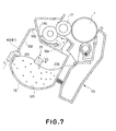
- the portion H1 of the top surface of the body of toner T rises along the portion W2, that is, the slanted portion, of the wall of the toner storage chamber 18a, eventually reaching the transparent members 40 and 41 as shown in Figure 7 .
- the detection light L emitted from the LED begins to be blocked by the body of toner T which enters the space between the pair of transparent members 40 and 41 which is attached to the wall of the toner storage chamber 18a.
- the phototransistor is prevented from receiving the detection light L (state corresponding to point (B) in graph in Figure 24 ).
- the portion H1 of the top surface of the body of toner T rises along the portion W2 of the internal surface of the toner storage chamber 18a, becoming thereby angled (V) relative to the horizontal plane.
- the portion W2 of the toner storage chamber wall is tilted toward the axial line of the toner stirring member 22 relative to the vertical plane. Further, in this embodiment, the portion W2 is flat. However, the portion W2 may be curved inward of the toner storage chamber 18a.
- the length RO ( Figure 3 ) of the shorter edges of the stirring sheet 22b (which is roughly the same as distance R01 from rotational axis O of toner stirring member 22 to sweeping edge 22bA of stirring sheet 22b), is greater than the distance from the axial line O of the stirring member 22 to the internal surface of the portion W2 of the toner storage chamber wall, as described above. Therefore, the possibility that the body of toner T, which is on the stirring sheet 22b, partially falls through the gap between the stirring sheet 22b and the internal surface of the portion W2 of the toner storage chamber wall is minimized.
- the toner stirring sheet 22b continues to convey the toner along the portion W2 of the toner storage chamber wall, until the sweeping edge 22bA of the toner stirring sheet 22b separate from the portion W2, at a point P.
- the development unit 4 is structured so that when the process cartridge 7 is in its image forming position in the main assembly of the image forming apparatus, the point P is on the inward side of the toner storage chamber 18a relative to the vertical plane coinciding with the most inward edges of the transparent members 40 and 41 with which the portion W2 of the toner storage chamber wall is provided. Therefore, it does not occur, as described above, that the remaining body of toner T on the toner stirring sheet 22b falls directly onto the transparent members 40 and 41.
- the detection light L remains blocked by the toner. That is, the amount by which the phototransistor receives the detection light L is unlikely to be affected by the falling toner, as will be evident from the pattern (waveform) of the changes in the relationship between the amount of the detection light L received by the light receiving portion, and the elapsed time, shown in the graph in Figure 24 . Therefore, the threshold value for precisely determine the amount of the toner remainder can be easily set.
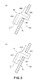
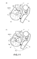
- Figures 11(a) and 11(b) correspond to the case in which the amount of the toner remaining in the toner storage chamber 18a is relatively large.
- Figure 25 shows the relationship (waveform) between the amount of detection light L which the phototransistor (unshown) receives when the amount of the toner remaining in the toner storage chamber 18a is relatively large, and the elapsed time.
- Figure 11(a) is a cross-sectional view of the development unit 4, which corresponds to a point T1 ( Figure 25 ) in elapsed time, at which the body of toner T has just reached the transparent members 40 and 41 by being pushed by the toner stirring sheet 22b.
- the point T1 in elapsed time is the point in time at which the detection light L, which has been allowed to transmit through the space between the transparent members 40 and 41, has just begun to be blocked by the body of toner T.
- Figure 11(b) is a cross-sectional view of the development unit 4, which corresponds to a point T2 ( Figure 25 ) in elapsed time, at which the toner stirring sheet 22b has just moved past the space between the transparent members 40 and 41.
- the point T2 in elapsed time is the point in elapsed time at which the body of toner T on the toner stirring sheet 22b has just moved out of the space between the transparent members 40 and 41 with which the portion W2 of the toner storage chamber wall is provided, that is, the point in elapsed time at which the detection light L has just begun to transmit again through the space between the transparent members 40 and 41.
- Figures 12(a) and 12(b) correspond to the case in which the amount of toner remaining in the toner storage chamber 18a is half the amount of toner remaining in the toner storage chamber 18a when the development unit 4 is in the state shown in Figures 11(a) and 11(b) .
- Figure 26 shows the relationship (waveform) between the amount of detection light L which the phototransistor (unshown) received when the amount of the toner remaining in the toner storage chamber 18a was as shown in Figures 12(a) and 12(b) , and the elapsed time.
- the angle by which the toner stirring member 22 rotates during the period between a point T3 in elapsed time ( Figure 26 ) at which the detection light L begins to be blocked again as shown in Figure 12(a) , and a point T4 ( Figure 26 ) in elapsed time at which the detection light L begins to transmit again though the space between the transparent members 40 and 41 as shown in Figure 12(b) is ⁇ .
- the amount of toner remaining in the toner storage chamber 18a is estimated based on the fact that the angle ( ⁇ ) by which the toner stirring member 22 rotates from the moment the detection light L begins to be blocked to the moment the detection light L begins to be allowed to transmit again through the space between the transparent members 40 and 41 is affected by the amount of toner remaining in the toner storage chamber 18a.
- the body of toner T which is being pushed up along the smooth inward surface of the portion W2 of the toner storage chamber wall, being therefore stable in behavior, is used to block the detection light L, or allow the detection light L to transmit through the space between the transparent members 40 and 41. Therefore, the length of time the detection light L remains blocked, and the length of time the detection light L is allowed to transmit through the space between the transparent members 40 and 41, are stable. Therefore, the amount of the toner remainder can be more precisely detected.
- the detection light L which is transmitting through the space between the transparent members 40 and 41 is blocked by pushing up the toner in the toner storage chamber 18a along the portion W2 of the wall of the toner storage chamber 18a, which is tilted toward the axial line of the toner stirring member 22 relative to the vertical direction, by the rotational toner stirring member 22.
- the transparent members 40 and 41 are attached to the portion W2 of the wall of the toner storage chamber 18a, which is tilted toward the axial line of the toner stirring member 22. Therefore, toner does not settle on the transparent members 40 and 41.
- the development unit 4 is structured so that when the process cartridge is in its image forming position in the main assembly of the image forming apparatus, the point P of the inward surface of the toner storage chamber wall, which corresponds to the point in elapsed time at which the sweeping edge of the stirring sheet 22b becomes freed from the portion W2 of the toner storage chamber wall, is on the inward side of the vertical plane which coincides with the most inward edges of the transparent members 40 and 41, that is, the point P is closer to the rotational axis of the toner stirring member 22 than the most inward edges of the transparent members 40 and 41.
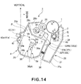
- Figure 14 is a schematic cross-sectional view of the process cartridge 7 (7a - 7d) in this embodiment, which is in its image forming position in the main assembly 100 of the electrophotographic image forming apparatus ( Figure 1 ).
- a cartridge 7a which contains yellow toner
- a cartridge 7b which contains magenta toner
- a cartridge 7c which contains cyan toner
- a cartridge 7d which contains black toner
- the process cartridge 7 (7a - 7d) is made up of a photosensitive member unit 26 (26a - 26d) and a development unit 4 (4a - 4d). Next, the two units 26 and 4 will be described.
- the photosensitive member unit 26 is provided with a photosensitive drum 1 (1a - 1d), a charge roller 2 (2a - 2d), and a cleaning member 6 (6a - 6d).
- the photosensitive drum 1 is rotatably attached with interposition of a pair of unshown bearings.
- the charge roller 2, and cleaning member 6 are disposed as descried above.
- the residual toner is removed from the peripheral surface of the photosensitive drum 1 by the cleaning member 6, it falls into a chamber 27a for the removed residual toner.
- the driving force from a driving motor (unshown) is transmitted to the photosensitive member unit 26, the photosensitive drum 1 is rotationally driven in the direction indicated by an arrow mark A in synchronism with the progression of the image forming operation.
- a pair of charge roller bearings 28 are attached so that the bearings 28 are movable in the direction indicated by a double-headed arrow mark C, the theoretical extension of which coincides with the axial lines of the charge roller 2 and photosensitive drum 1.
- the shaft 2j of the charge roller 2 is rotatably borne by the pair of charge roller bearings 28, which are kept pressured toward the photosensitive drum 1 by a pair of pressure applying member 46.
- the developing means frame 29 of the development unit 4 has a developer storage chamber 29a (which hereafter will be referred to as toner chamber) and a development chamber 29b.
- the toner chamber 29b stores toner.
- the development roller 25 rotates in contact with the photosensitive drum 1, in the direction indicated by an arrow mark D.
- the development chamber 29b is above the toner chamber 29a.
- the toner chamber 29a and development chamber 29b are in connection to each other, through a hole 29c, with which the partition wall between the two chambers 29b and 29a is provided.
- the development roller 25 in the development chamber 29b is rotatably supported by a developing means frame 29. More specifically, the development roller 25 is supported at its lengthwise end portions by a pair of bearings (unshown) attached to the lengthwise ends of the developing means frame 29.
- the development unit 4 is also provided with a developer supply roller 34 (which hereafter will be referred to as toner supply roller) and a development blade 35, which are in the adjacencies of the peripheral surface of the development roller 25.
- the toner supply roller 34 rotates in contact with the development roller 25 in the direction indicated by an arrow mark E.
- the development blade 35 is a blade for regulating in thickness the toner layer on the peripheral surface of the development roller 25.
- the toner chamber 29a of the developing means frame 29 is provided with a recess 42 which is recessed outward from the toner chamber 29, as will be described later in detail.
- This recess 42 is provided with a pair of transparent members 40 and 41 as developer remainder amount detecting members (which is means for detecting amount of developer (toner) remainder) for detecting the amount of the developer remaining in the toner chamber 29a.
- the transparent members 40 and 41 are provided with a light exit portion 40a, through which the detection light L exits from the transparent member 40, whereas the transparent member 41 has a light entrance portion 41a, through which the detection light L enters the transparent member 41, respectively.
- toner stirring member 36 for stirring the toner in the toner storage chamber 29a while conveying the toner to the abovementioned toner supply roller 34.
- the toner stirring member 36 is provided with a cleaning member 39 (which hereafter may be referred to transparent member cleaning member) for cleaning the light exit portion 40a and light entrance portion 41a.
- the development unit 4 is pivotally connected to the photosensitive member unit 26. More specifically, the bearing members 32R and 32L are provided with holes 32Rb and 32La, and a pair of connective pins 37R and 37L are put through the holes 32Ra and 32La and the corresponding holes of the photosensitive member unit 26 so that the development unit 4 is pivotally movable relative to the photosensitive member unit 26.
- the process cartridge 7 is under the pressure from compression springs 24 for pressing the development unit 4. Therefore, during an image forming operation, the process cartridge 7 is pivoted about the connective pins 37 R and 37L in the direction indicated by an arrow mark F, whereby the development roller 25 is placed in contact photosensitive drum 1.
- toner stirring member 36 in the toner chamber 29a which stores toner.
- the toner in the toner chamber 29a is conveyed to a toner supply roller 34 through the hole 29c, by rotating the stirring member 36 in the direction X.
- the development unit 4 is structured so that the point P at which the sweeping edge of the toner stirring member 36 is freed from the internal surface of the portion Wa of the toner storage chamber wall, is on the inward side of the vertical plane which coincides with the most inward edges of the transparent member 40 and 41, that is, the vertical plane which coincides with the point P is closer to the rotational axis O of the toner stirring member 36 than the vertical plane coinciding with the most inward edges of the transparent members 40 and 41.
- the wall W of the toner chamber 29a has a bottom portion Wb and a lateral portion Wa
- the bottom portion Wb is the portion which is at the bottom when the cartridge is properly set in its image forming position, that is, when the attitude of the cartridge is as shown in Figure 14 .
- the lateral Wa is on the downstream side of the bottom portion Wb. It is tilted toward the axial line of the toner stirring member 36, relative to the vertical direction. It is the lateral portion Wa that is provided with the recess 42 which is provided with the pair of toner remainder amount detecting member, that is, the transparent members 40 and 41, as will be described later in later.
- the wall W of the toner chamber 29a has a portion Wc, that is, the rest of the wall W of the toner chamber 29a, which is between the abovementioned tilted portion Wa (lateral portion) and portion Wb (bottom portion) in terms of the rotational direction of the toner stirring member 36, and connects the two portions Wa and Wb of the wall W of the toner chamber 29a.
- the sweeping edge 36bA moves in contact with the bottom portion Wb, lateral portions Wa (tilted portion), etc., as will be described later in detail.
- the toner T in the toner chamber 29a is guided to the hole 29c along the bottom portion Wb, and then, along the portion Wa.
- the toner stirring member 36 As the toner stirring member 36 is rotated, a part of the body of toner T in the toner chamber 29a fails to be guided into the hole 29c, that is, it falls from the toner stirring member 36 and settles back in the bottom portion of the toner chamber 29a, whereas the other part is guided inward of the toner chamber 29a, along the portion Wc of the toner storage chamber wall, by the toner stirring member 36.
- the toner stirring member 36 is made up of a shaft 36a and a stirring sheet 36b.
- the shaft 36a is molded of a resinous substance.
- the stirring sheet 36b is the very portion of the toner stirring member 36 that stirs toner. It is a rectangular sheet made of flexible resinous sheet. Its longer edges, that is, the edges parallel to the lengthwise direction of the shaft 36a, have a length of W0, and its shorter edges, that is, the edges parallel to the radius direction of the sweeping area of the stirring sheet 36b, that is, the distance from the rotational axis of the shaft 36a to the sweeping edge of the stirring sheet 36b, have a length of H0.
- the stirring sheet 36b is attached to the shaft 36a by one of the longer edges.
- the cleaning member 39 for cleaning the light exit surface 40a and light entrance surface 41a is on the downstream side of the stirring sheet 36b.
- the cleaning member 39 is made up of a wiping sheet 39a and an auxiliary wiping sheet 39b.
- the wiping sheet 39a is a flexible sheet for wiping away the toner having adhered to the light exit surface 40a, and the light entrance surface 41a.
- the auxiliary wiping sheet 39b is a member which assists the wiping sheet 39a in cleaning the light exit surface 40a and light entrance surface 41a.
- the auxiliary wiping sheet 39b is attached to the shaft 36a by one of its edges parallel to the shaft 36a. It is also attached to the wiping sheet 39a by the other edge parallel to the shaft 36a. That is, the auxiliary wiping sheet 36b plays the role of the supporting member for attaching the wiping sheet 39a to the shaft 36a.
- the shaft 36a is rectangular in cross section.
- the toner stirring member 36 (stirring sheet 36b) is attached to one of the surfaces of the shaft 36a.
- the transparent member cleaning member 39 (more specifically, auxiliary wiping sheet 39b) is attached to the opposite surface of the shaft 36a from the surface to which the toner stirring member 36 is attached. Therefore, in terms of the rotational direction of the toner stirring member 36, the transparent member cleaning member 39 is on the downstream side relative to the toner stirring member 36 by a distance equivalent to the measurement (d) of the shaft 36a ( Figure 14 ).
- the wiping sheet 39a is in the form of an isosceles trapezoid. That is, the wiping edge 39aB of the wiping sheet 39a, that is, the outward edge in terms of the radius direction of the sweeping area of the toner stirring member 36 is narrower (W1a) than the edge 29aC, that is, the inward (other) edge (W2a) in terms of the abovementioned radius direction, which is closer to the shaft 36a by the height H1a (W1a ⁇ W2a).
- the pair of lateral edges 39aA of the trapezoidal wiping sheet 39a wipe away the toner having adhered to the light exit surface 40a and light entrance surface 41a, by coming into contact with the light exit surface 40a and light entrance surface 41a.
- the distance H0a from the axial line of the shaft 36a to the wiping edge 39aB of the wiping sheet 39a is roughly the same in value as the abovementioned measurement H0 of the stirring sheet in terms of the radius direction of the sweeping area of the toner stirring member 36.
- the stirring sheet 36b and wiping sheet 39a can be easily made of flexible resinous sheet, such as polyester film, polyphenylene sulfide film, or the like.
- the thickness of the stirring sheet 22b is desired to be in a range of 50 - 250 ⁇ m.
- the force for driving the stirring member 36 is transmitted to the stirring member 36 by a driver gear (unshown) attached to one of the lengthwise ends of the shaft 36a; the shaft of the driver gear is inserted in the hole 36c, with which one of the lengthwise ends of the shaft 36a is provided, through the hole with which one of the lateral walls of the toner chamber 29a of the developing means frame 29 is provided.
- a driver gear (unshown) attached to one of the lengthwise ends of the shaft 36a; the shaft of the driver gear is inserted in the hole 36c, with which one of the lengthwise ends of the shaft 36a is provided, through the hole with which one of the lateral walls of the toner chamber 29a of the developing means frame 29 is provided.
- the light exit surface 40a and light entrance surface 41a for detecting the amount of the toner remainder, based on the amount of light transmission are positioned so that they oppose each other, in terms of the direction parallel to the rotational axis of the toner stirring member 36.
- the light exit surface 40a is an integral part of the transparent member 40 which guide the detection light L in emitted from the LED (unshown), as a light emitting portion, with which the main assembly 100A of the electrophotographic image forming apparatus is provided, into the recess 42 (that is, toner chamber 29a).
- the light exit surface 41a is an integral part of the transparent member 41, which guides the detection light Lout to the phototransistor (unshown), as the light receiving portion, with which the main assembly 100A of the electrophotographic image forming apparatus is provided, after the detection light L transmits through the recessed portion 42.
- the transparent members 40 and 41 may be integrated into a single component.
- the cleaning member 39 rotates, not only do the wiping sheet 39a and auxiliary wiping sheet 39b of the cleaning member 39 clean the light exit surface 40a and light entrance surface 41a, but also, block the detection light L while they are wiping the light exit surface 40a and light entrance surface 41a.
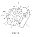
- Figure 16 is a cross-sectional view of the process cartridge 7 immediately after the cleaning of the light exit surface 40a and light entrance surface 41a, respectively, by the cleaning member 39.
- the detection light L transmits through the recess 42, and is detected by the light receiving portion in the main assembly of the image forming apparatus, through the light exit surface 41a.
- Figure 17 is a cross-sectional view of the process cartridge 7 immediately before the light exit surface 40a and light entrance surface 41a, respectively, are cleaned by the cleaning member 39.
- the detection light L is blocked in the recess 42 by the body of toner T, which is being conveyed by the toner stirring member 36, and therefore, it does not reach the light exit surface 41a. Thus, it is not received by the light receiving portion in the main assembly of the image forming apparatus.
- the amount of the toner remaining in the toner chamber 29a can be estimated based on the length of time the detection light L transmits through the toner chamber 29a (that is, recessed portion 42), that is, the length of time the detection light L is received by the light receiving portion of the image forming apparatus, per rotation of the toner stirring member 36.
- the amount of the toner remainder is detected by the pair of transparent members 40 and 41, based on the light transmission through the transparent members 40 and 41.
- the detection light L in emitted from the light emitting portion (unshown), such as a LED, attached to the main assembly of the image forming apparatus is guided to the transparent member 40.
- the detection light L in is deflected by 90°, by the reflective surface 40r of the transparent member 40, being thereby guided toward the light exit surface 40a of the transparent member 40, and exits from the transparent member 40 through the light exit surface 40a.
- the detection light L travels through the process cartridge, and is guided into the light entrance surface 41a of the transparent member 41, that is, the other transparent member, which opposes the transparent member 40. Entering the transparent member 41, the detection light L is deflected by 90°by the reflective surface 41r of the transparent member 41. Then, the detection light L travels through the transparent member 41, and exits from the transparent member 41, that is, exits from the process cartridge. Exiting from the process cartridge, the detection light Lout is guided to the light receiving portion, such as a phototransistor, attached to the main assembly of the image forming apparatus.
- the light receiving portion such as a phototransistor
- the transparent members 40 and 41 are structured and positioned (attached to development unit 4) so that the distance W2 between the inward edges of the mutually opposing light exit surface 40a and light entrance surface 41a is greater than the outward edges of the mutually opposing light exit surface 40a and light entrance surface 41a (that is, W2 > W1) .
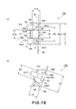
- the wiping sheet 39a is rendered trapezoidal, as described above. Also in order to ensure that the wiping sheet 39a of the cleaning member 39 cleans the light exit surface 40a and light entrance surface 41a by elastically contacting the surfaces 40a and 41a, the wiping sheet 39a is rendered slightly larger than the trapezoidal area which the mutually opposing light exit surface 40a and light entrance surface 41a form as shown in Figure 18(a) .
- the toner on the toner stirring member 36 and the toner on the cleaning member 39 sometimes fall from the toner stirring member 36 and/or cleaning member 39, respectively, and adheres to the light exit surface 40a and light entrance surface 41a, immediately after the cleaning of the surfaces 40a and 41a by the cleaning member 39. Therefore, the detection light L is sometimes blocked by the toner fell from the stirring member 36 and/or cleaning member 39 immediately after the cleaning. Further, the detection light L is sometimes blocked because the toner particles floating in the toner chamber 29a adhere to the light exit surface 40a and light entrance surface 41a.
- the transparent members 40 and 41 are attached to the portion Wa of the toner chamber wall, which will be above the horizontal plane H which coincides with the rotational axis O of the stirring member 36 when the process cartridge is in its image forming position in an image forming apparatus. Further, the portion Wa of the wall of the toner chamber 29a is tilted so that a straight line Va drawn perpendicularly and inwardly from the portion Wa is on the bottom side of the horizontal plane which coincides with the point of the portion Wa, from which the straight line Va is drawn.
- the development unit 4 is structured so that a straight line Vb drawn inward of the toner chamber 29a from the light exit surface 40a (41a), and perpendicularly to the light exit surface 40a (41a), is under the horizontal plane which coincides with the point of the light exit surface 40a, from which the straight line Vb is drawn.
- the angle of the top surface of the body of developer in the toner chamber 29a is affected by the angle of the axial line of the stirring member during the mounting of the process cartridge. Therefore, in order to reduce the effect of the inclination of the surface of the body of developer in the toner chamber 29a, the light exit surface 40a and light entrance surface 41a are desired to be positioned roughly at the middle of the toner chamber 29a in terms of the direction parallel to the axial line of the stirring member 36.
- the toner chamber 29a is provided with the recess 42, which is recessed outward from the toner chamber 29a in the radius direction of the sweeping area of the stirring member 36. More specifically, the portion Wa of the wall W of the toner chamber 29a, which is between the portions Wb and Wc of the wall W of the toner chamber 29a, is provided with the recess 42.
- the recess 42 is a boxy space which opens to the toner chamber 29a, and the opening of which has a size of w1 (length of edge perpendicular to axial line of toner stirring member) x w3 (length of edge parallel to axial line of toner stirring member).
- the recess 42 has lateral walls 42a1 and 42a2 which oppose each other in terms of the direction parallel to the rotational axis of the toner stirring member 36, and walls 42b1 and 42b2 which oppose each other in terms of the rotational direction of the toner stirring member 36.
- the recess 42 has the bottom wall which holds a distance h from the plane of the opening 42A of the recess 42, that is, the border between the recess 42 and toner chamber 29a, and has a size of w2 x w3.
- the transparent members 40 and 41 are attached to the bottom wall 42c of the recess 42.
- the wall of the recess 42 is an integral part of the portion Wa (tilted portion) of the wall W of the toner chamber 29a (that is, development means frame 29).
- the wall of the recess 42, and the pair of transparent members 40 and 41 may be integrally formed as a single piece, which is attachable to the portion Wa of the wall W of the toner chamber 29a (that is, developing means frame 29).
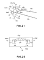
- the development unit 4 (recess 42) is structured so that there is a gap g between the most inward edge of the surface 40a (41a) of the transparent member 40 (41) and the plane of the opening 42A of the recess 42 ( Figure 18(b) and 21 ).
- the value of the gap g has only to be such that the transparent members 40 and 41 is prevented from protruding beyond the plane coinciding the inward surface of the portion Wa of the toner chamber wall. That is, the gap g is to be provided to prevent the problem that the toner stirring member 36 deform by hanging up on the transparent members 40 and 41.
- the development unit 4 (recess 42) is structured so that there is a certain amount of distance between the light exit surface 40a (and light entrance surface 41a) and the bottom wall 42c. This structural arrangement is made to prevent the problem that sometimes, the amount of the toner remainder cannot be accurately detected because toner sometimes fails to reach the adjacencies of the bottom wall 42c.
- the above described structural arrangement is employed to ensure that the detection light L remains satisfactorily blocked until the sweeping edge 36bA of the stirring sheet 36b begins to move through the adjacencies of the light exit surface 40a and light entrance surface 41a, and also, to better control the toner in its behavior while the sweeping edge 36bA of the stirring sheet 36b moves through the adjacencies of the light exit surface 40a and light entrance surface 41a.
- the wiping sheet 39a which is on the downstream side of the stirring sheet 36b in terms of the rotational direction of the toner stirring member 36, enters the space between the light exit surface 40a and light entrance surface 41a.
- the development unit 4 toner chamber 29a
- the wiping sheet 39a for cleaning the light exit surface 40a and light entrance surface 41a comes into contact with the sweeping edge 36bA of the stirring sheet 36b when the wiping sheet 39a enters the space between the light exit surface 40a and light entrance surface 41a.
- this embodiment is superior to the first embodiment in terms of keeping the detection light L satisfactorily blocked while the sweeping edge 36bA of the stirring sheet 36b move through the adjacencies of the light exit surface 40a and light entrance surface 41a.
- the development unit 4 (toner chamber 29a) is structured so that the wiping sheet 39a for cleaning the light exit surface 40a and light entrance surface 41a comes into contact with the sweeping edge 36bA of the stirring sheet 36b when the wiping sheet 39a enters the space between the light exit surface 40a and light entrance surface 41a, and also, so that the wiping sheet 39a begins to clean the light exit surface 40a and light entrance surface 41a the moment the body of toner T, which is being conveyed by the stirring sheet 36b, finishes moving through the space between the light exit surface 40a and light entrance surface 41a.
- the cleaning member 39 cleans the light exit surface 40a and light entrance surface 41a by being moved through the space between the light exit surface 40a and light entrance surface 41a, which are aligned in the direction parallel to the rotational axis of the toner stirring member 36.
- the rigidity of the wiping sheet 39a in terms of the vertical direction needs to greater than a certain value.
- the piping sheet 39a is excessively increased in rigidity, the wiping sheet 39a cannot be moved into the space between the light exit surface 40a and light entrance surface 41a.
- the rigidity of the wiping sheet 39a in terms of the direction parallel to the circumferential direction of the sweeping area of the toner stirring member 36 needs to be greater than the rigidity of the wiping member 39a in terms of the direction perpendicular to the light exit surface 40a and light entrance surface 41a.
- the cleaning member 39 in order to add to the rigidity of the wiping sheet 39a in terms of the circumferential direction of the sweeping area of the toner stirring member 36, the cleaning member 39 is provided with the auxiliary wiping sheet 39b, which is positioned on the downstream side of the wiping sheet 39a in terms of the rotational direction of the stirring member.
- the width W3 of the edge of the auxiliary wiping sheet 39b on the wiping sheet side is less than the width W1a of the wiping edge 39aB of the wiping sheet 39a, which is perpendicular to the light exit surface 40a and light entrance surface 41a (W3 ⁇ W1a). Further, the auxiliary wiping sheet 39b is shaped so that the width W3 is less than the shortest distance W1 between the light exit surface 40a and light entrance surface 41a (W3 ⁇ W1).
- the light exit surface 40a and light entrance surface 41a are tilted so that their inward edges in terms of the radius direction of the sweeping area of the toner stirring member 36, is longer than their outward edges (W1 ⁇ W2). Therefore, the wiping sheet 39a is shaped so that the its inward edge 39aC, in terms of the radius direction of the stirring member 36, is longer than its outward edge 39aB (W2a > W1a).
- the wiping sheet 39a is shaped and sized to ensure that even if the wiping sheet 39a deforms and/or creeps, or the like problems occur, it can still wipe clean the light exit surface 40a and light entrance surface 41a across their entire range in terms of the circumferential direction of the sweeping area of the toner stirring member 36. That is, the wiping sheet 39a is rendered long enough, in terms of the radius direction of the sweeping area of the toner stirring member 36, to enter the portion of the recess 42, which is between the light exit surface 40a and light entrance surface 41a, deep enough to reach the bottom wall 42c of the recess 42.
- a gap g1 which is the gap between the transparent member 40 (41) and the lateral wall 42b1, which is the downstream wall of the recess 42 in terms of the rotational direction of the toner stirring member 36
- a gap g2 which is the gap between the transparent member 40 (41) and the lateral wall 42b2, which is the upstream wall of the recess 42 in terms of the rotational direction of the toner stirring member 36
- the wiping sheet 39a moves past the space between the light exit surface 40a and light entrance surface 41a, the wiping sheet 39a is freed from the restriction placed on the wiping sheet 39a by the light exit surface 40a and light entrance surface 41a, and therefore, it springs back into its normal shape because of its resiliency.
- the toner T on the wiping sheet 39a is catapulted downward in terms of the rotational direction of the toner stirring member 36, in the recess 42.
- the toner T on the wiping sheet 39a falls through the space between the light exit surface 40a and light entrance surface 41a after the cleaning of the light exit surface 40a and light entrance surface 41a. As the toner T falls, it sometimes adheres again to the light exit surface 40a and light entrance surface 41a.
- a space S is provided between the transparent members 40 and 41, and lateral walls 42a1 and 42a2, respectively, of the recess 42, as shown in Figure 22 .
- the toner borne on the wiping sheet 39a while the wiping sheet 39a moves between the light exit surface 40a and light entrance surface 41a falls through the gaps S between the transparent members 40 and 41, and lateral walls 42a1 and 42a2, respectively, of the recess 42. Therefore, when the wiping sheet 39a moves out of the space between the light exit surface 40a and light entrance surface 41a, there remains only a small amount of toner on the wiping sheet 39a.
- the problem that the amount of the toner remainder in the toner chamber 29a is inaccurately detected because of the variation in the amount of the toner which adheres again to the light exit surface 40a and light entrance surface 41a after the light exit surface 40a and 41a are cleaned, can be reduced by reducing the amount by which toner T remains on the wiping sheet 39a when the wiping sheet 39a moves out of the space between the light exit surface 40a and light entrance surface 41a, that is, when the wiping sheet 39a kept deformed while moving between the light exit surface 40a and light entrance surface 41a is allowed to spring back into its normal shape.
- the body of toner T which entered the recess 42 during the period in which the detection light L was blocked, remains in the recess 42 even after the passage of the cleaning member 39 through the space between the light exit surface 40a and light entrance surface 41a, the toner sometimes adheres to the light exit surface 40a and light entrance surface 41a, and therefore, blocks the detection light L, after the cleaning of the light exit surface 40a and light entrance surface 41a.
- the lateral wall 42b2 of the recess 42 that is, the lateral wall of the recess 42, which is on the bottom side, and on the upstream side in terms of the rotational direction of the toner stirring member 36 ( Figure 18 ), is tilted by the angle of ⁇ , the value of which is large enough to cause the toner T to fall into the toner chamber 29a.
- This structural arrangement is for preventing the toner T from remaining in the recess 42 after the cleaning member 39 moves between the light exit surface 40a and light entrance surface 41a.
- this embodiment offers the same effects as the first embodiment, but also, can prevent the problem that during the period in which the detection light L is to be allowed to transmit through the space between the light exit surface 40a and light entrance surface 41a, the toner adheres to the light exit surface 40a and light entrance surface 41a immediately after the cleaning of the light exit surface 40a and light entrance surface 41a.
- the toner in the toner chamber 29a is moved into the light passage L by the stirring member 36 to block the detection light L. Therefore, the length of time the detection light L remains blocked is not affected by the change in the fluidity of the toner. Further, the light exit surface 40a and light entrance surface 41a are more efficiently wiped clean by the cleaning member 39.
- the use has been made with a toner remainder amount detecting means of the light transmission type, but the present invention is no limited to the toner remainder amount detecting means of this type, and those utilizing electrostatic capacity is usable.
- the developer detecting member is attached to the portion of the developer storage chamber wall, along which the developer stirring member conveys upward the developer in the developer storage chamber into the development chamber located on top of the developer storage chamber. Therefore, the amount of the developer remaining in the developer storage chamber can be detected while the body of developer is stable. Therefore, the amount of the developer remainder can be more precisely detected. Further, the developer remainder amount detecting method based on the amount of light transmission is employed. Therefore, the amount of the developer remainder can be detected with the use a small number of components which are inexpensive. Therefore, it is possible to provide a developing apparatus, a process cartridge, and an electrophotographic image forming apparatus, which are significantly lower in cost than those in accordance with the prior art.
- a developing apparatus for use with an electrophotographic image forming apparatus includes a developer accommodating chamber for accommodating a developer; a developer chamber including the developer carrying member for carrying and feeding a developer supplied from the developer accommodating chamber to develop an electrostatic latent image formed on an electrophotographic photosensitive member; a developer stirring member, rotatably provided in the developer accommodating chamber, for stirring the developer in the developer chamber then, supplying the developer from the developer accommodating chamber into the developer chamber through an opening formed in an upper part of the developer accommodating chamber; a wall surface, provided in the developer accommodating chamber, for being contacted by a free end portion of the developer stirring member while the developer stirring member is moving, wherein the developer stirring member lifts the developer toward the opening along the wall surface in the developer accommodating chamber; a developer detector for detecting a remaining amount of the developer; wherein a position where the free end portion of the developer stirring member separates from the wall surface is above the developer detecting member and inside the developer accommodating chamber.
Landscapes
- Physics & Mathematics (AREA)
- General Physics & Mathematics (AREA)
- Dry Development In Electrophotography (AREA)
Abstract
a wall surface (W2,W3), provided in the developer accommodating chamber, for being contacted by a free end portion of the developer stirring member while the developer stirring member is moving, wherein the developer stirring member lifts the developer toward the opening along the wall surface in the developer accommodating chamber; a developer detector for detecting a remaining amount of the developer; wherein a position where the free end portion of the developer stirring member separates from the wall surface is above the developer detecting member and horizontally displaced towards the inside the developer accommodating chamber.
Description
- The present invention relates to an electrophotographic image forming apparatus, a developing apparatus employed by an electrophotographic image forming apparatus, and a process cartridge removably mountable in an electrophotographic image forming apparatus.
- Here, an "electrophotographic image forming apparatus" means an apparatus which forms an image on recording medium, using an electrophotographic image forming method. Examples of an electrophotographic image forming apparatus include an electrophotographic copying machine, an electrophotographic printer (laser beam printer, LED printer, etc.), a facsimile apparatus, a wordprocessor, and a multifunction apparatus capable of performing two or more functions of the preceding apparatuses, etc.
- A "developing apparatus" means an apparatus which develops an electrostatic latent image on an image bearing member, such as an electrophotographic photosensitive drum, into a visible image, with the use of developer.
- The process cartridge means a cartridge in which at least a developing means and an electrophotographic photosensitive drum, are integrally disposed so that they can be removably mountable in the main assembly of an electrophotographic image forming apparatus.
- As has been known, an image forming apparatus, such as a copying machine, a printer, or a facsimile machine, forms an electrostatic latent image on an image bearing member, such as an electrophotographic photosensitive member, and develops the electrostatic latent image into a visible image, more specifically, a visible image formed of toner, with the use of a developing apparatus.
- In the past, in the field of an image forming apparatus employing an electrophotographic image formation process, a process cartridge system has long been in use, according to which an electrophotographic photosensitive member, and one or more process cartridges which act on the electrophotographic photosensitive member, are integrally disposed in a cartridge removably mountable in the main assembly of an image forming apparatus. A process cartridge system makes it possible for a user to maintain an electrophotographic image forming apparatus without relying on a service person. Therefore, it can drastically improve an electrophotographic image forming apparatus, in terms of operability.
- One of the primary reasons for process cartridge replacement is developer (toner) depletion. Thus, in order to prompt user of timely process cartridge replacement by giving in advance the user the information regarding the amount of toner remainder, some of recent electrophotographic image forming apparatuses are designed so that they detect the amount of the toner remaining in a process cartridge. There are various methods usable for detecting the amount of toner remainder.
- One of the methods for detecting the amount of the toner remainder is recorded in
Japanese Laid-open Patent Application 2003-131479 Figure 5 ), according to which the amount of the toner remainder is detected based on the amount of light transmission. Here, the general concept of detecting the amount of the toner remainder based on the amount of light transmission will be described with reference to a developingapparatus 104 showing inFigure 13 . - A beam of light for detecting the amount of the toner remainder (which hereafter may be referred to simply as detection light), which is emitted from a light emitting portion, such as an LED, attached to the main assembly of an image forming apparatus, is guided through a light guide (unshown) attached to the image forming apparatus or the
toner container 141 of a process cartridge, and then, into thetoner container 141 through atransparent window 173 of thetoner container 141. - The
toner container 141 is structured so that as the detection light L enters thetoner container 141, it comes out, or fails to come out, of thetoner container 141 through another transparent window or the like. It depends on various factors such as the amount of toner in thetoner container 141 whether or not the detection beam L comes out of thetoner container 141. As the detection light L of comes out of the light exit window, it is guided to a light receiving portion (unshown), such as a phototransistor, by a light guide (unshown), such as the abovementioned light guide, attached to the main assembly of the image forming apparatus, or thetoner container 141. The light receiving portion is attached to the main assembly of the image forming apparatus, or the like. - Generally, there are a pair of rotational stirring
members toner container 141. The stirringmembers development roller 140 while stirring the toner. As the detection light L enters thetoner container 141 while thestirring member members toner container 141, the longer the length of time the detection light L is allowed to transmit through thetoner container 141. Thus, the amount of toner (toner remainder) in thetoner container 141 can be estimated by measuring the length of time the detection light L is allowed to transmit through thetoner container 141. This method of detecting (estimating) the amount of the toner remainder in thetoner container 141 is referred to as a toner remainder amount detecting method of the light transmission type. - The present invention is the further development of the prior art described above.
- In the case of the prior art described above, as the
stirring members toner container 141 are rotated, the toner having adhered to thetransparent windows members toner container 141 until the toner covers again thetransparent windows windows Figure 23 ; a waveform shown inFigure 23 is obtained. As the control portion of the main assembly of the image forming apparatus receives, from the light receiving portion, the electric signals which correspond to the amount of the light received by the light receiving portion, it measures the length of the periods a1, a2, a3, ... of time, in which the amount of the received light is no less than a preset value (threshold value). Then, based on the measured length of the periods of time, the control portion calculates (estimates) the amount of the toner remainder in thetoner container 141. - However, the pattern of the changes in the amount of the light received by the light receiving portion, which is expressed in the waveform in
Figure 23 , is affected by the shape of thetoner container 141, the positional relationship between thetransparent windows members Figure 23 , the periods a1, a2, a3, ... become different in length, affecting thereby the accuracy with which the amount of the toner remainder in thetoner container 141 can be detected. - The present invention is made in consideration of the problem described above. Thus, the primary object of the present invention is to provide a developing apparatus, a process cartridge, and an electrophotographic image forming apparatus, the amount of the developer remainder in which can be precisely detected.
- According to an aspect of the present invention, there is provide a developing apparatus for use with an electrophotographic image forming apparatus, said developing device comprising a developer accommodating chamber for accommodating a developer; a developer chamber including the developer carrying member for carrying and feeding a developer supplied from said developer accommodating chamber to develop an electrostatic latent image formed on an electrophotographic photosensitive member; a developer stirring member, rotatably provided in said developer accommodating chamber, for stirring the developer in said developer chamber then, supplying the developer from said developer accommodating chamber into said developer chamber through an opening formed in an upper part of said developer accommodating chamber; a wall surface, provided in said developer accommodating chamber, for being contacted by a free end portion of said developer stirring member while said developer stirring member is moving, wherein said developer stirring member lifts the developer toward said opening along said wall surface in said developer accommodating chamber; a developer detecting member, provided at said wall surface, for detecting a remaining amount of the developer by transmitting detecting light detected light into said developer accommodating chamber; wherein a position where the free end portion of said developer stirring member separates from said wall surface is above said developer detecting member and inside said developer accommodating chamber.
- According to another aspect of the present invention, there is provide a process cartridge detachably mountable to a main assembly of an electrophotographic image forming apparatus, said process cartridge comprising an electrophotographic photosensitive member on which an electrostatic latent image is formed; a developer accommodating chamber for accommodating a developer; a developer chamber including the developer carrying member for carrying and feeding a developer supplied from said developer accommodating chamber to develop said electrostatic latent image formed on an electrophotographic photosensitive member; a developer stirring member, rotatably provided in said developer accommodating chamber, for stirring the developer in said developer chamber then, supplying the developer from said developer accommodating chamber into said developer chamber through an opening formed in an upper part of said developer accommodating chamber, when said process cartridge is mounted to the main assembly of the electrophotographic image forming apparatus; a wall surface, provided in said developer accommodating chamber, for being contacted by a free end portion of said developer stirring member while said developer stirring member is moving, wherein said developer stirring member lifts the developer toward said opening along said wall surface in said developer accommodating chamber; a developer detecting member, provided at said wall surface, for detecting a remaining amount of the developer by transmitting detecting light detected light into said developer accommodating chamber; wherein a position where the free end portion of said developer stirring member separates from said wall surface is above said developer detecting member and inside said developer accommodating chamber.
- According to a further aspect of the present invention, there is provided an electrophotographic image forming apparatus for forming an image on a recording material, said apparatus comprising:
- (i) a developing device including, a developer accommodating chamber for accommodating a developer, a developer chamber including the developer carrying member for carrying and feeding a developer supplied from said developer accommodating chamber to develop an electrostatic latent image formed on an electrophotographic photosensitive member, a developer stirring member, rotatably provided in said developer accommodating chamber, for stirring the developer in said developer chamber then, supplying the developer from said developer accommodating chamber into said developer chamber through an opening formed in an upper part of said developer accommodating chamber; a wall surface, provided in said developer accommodating chamber, for being contacted by a free end portion of said developer stirring member while said developer stirring member is moving, wherein said developer stirring member lifts the developer toward said opening along said wall surface in said developer accommodating chamber, a developer detecting member, provided at said wall surface, for detecting a remaining amount of the developer by transmitting detecting light detected light into said developer accommodating chamber, wherein a position where the free end portion of said developer stirring member separates from said wall surface is above said developer detecting member and inside said developer accommodating chamber; and
- (ii) feeding means for feeding the recording material.
- These and other objects, features, and advantages of the present invention will become more apparent upon consideration of the following description of the preferred embodiments of the present invention, taken in conjunction with the accompanying drawings.
-
-
Figure 1 is a schematic sectional view of the image forming apparatus in the first embodiment of the present invention, showing the general structure of the apparatus. -
Figure 2 is a cross-sectional view of the process cartridge in the first embodiment of the present invention, showing the general structure of the cartridge. -
Figure 3 is a schematic perspective view of the toner stirring member. -
Figure 4 is a top view of the transparent member. -
Figures 5(a) and 5(b) are sectional views of the transparent member, at planes A-A and B-B, respectively, inFigure 4 . -
Figure 6 is a schematic cross-sectional view of the process cartridge, showing the operation of the toner stirring member in the cartridge. -
Figure 7 is a schematic cross-sectional view of the process cartridge, showing the operation of the toner stirring member in the cartridge. -
Figure 8 is a schematic cross-sectional view of the process cartridge, showing the operation of the toner stirring member in the cartridge. -
Figure 9 is a schematic cross-sectional view of the process cartridge, showing the operation of the toner stirring member in the cartridge. -
Figure 10 is a schematic cross-sectional view of the process cartridge, showing the operation of the toner stirring member in the cartridge. -
Figure 11 is a schematic cross-sectional view of the process cartridge, showing the operation of the toner stirring member in the cartridge. -
Figure 12 is a schematic cross-sectional view of the process cartridge, showing the operation of the toner stirring member in the cartridge. -
Figure 13 is a schematic cross-sectional view of a typical process cartridge in accordance with the prior art. -
Figure 14 is a schematic cross-sectional view of the process cartridge in another (second) embodiment of the present invention, showing the general structure of the cartridge. -
Figure 15 is a perspective view of the stirring member and transparent member cleaning member of the developing apparatus in accordance with the present invention. -
Figure 16 is a schematic cross-sectional view of the developing apparatus, in the second embodiment, which is in the state in which the toner remainder amount detection light L is received by the light receiving portion. -
Figure 17 is a schematic cross-sectional view of the developing apparatus in the second embodiment, which is in the state in which the toner remainder amount detection light L is not received by the light receiving portion. -
Figure 18(a) is a horizontal sectional view a transparent member of the light transmission type, which is made up of a pair of transparent portions for detecting the amount of the toner remainder based on the amount of light transmission, andFigure 18(b) is a vertical sectional view (at plane parallel to front panel of apparatus) of the transparent member of the light transmission type, which is made up of a pair of transparent portions for detecting the amount of the toner remainder based on the amount of light transmission. -
Figure 19(a) is a horizontal sectional view a transparent member of the light transmission type, which is made up of a pair of transparent portions for detecting the amount of the toner remainder, andFigure 19(b) is a vertical sectional view (at plane parallel to front panel of apparatus) of the transparent member of the light transmission type, which is made up of a pair of transparent portions for detecting the amount of the toner remainder. -
Figure 20 is a cross-sectional view of the developing apparatus, which is in the state in which its light receiving portion does not receive the toner remainder amount detection light. -
Figure 21 is a cross-sectional view of the transparent member, its adjacencies, stirring sheet, and wiping sheet of the development unit, showing the relationship between the stirring sheet and wiping sheet when the wiping member begins to clean the transparent member. -
Figure 22 is a schematic sectional view (at vertical plane) of the transparent member and wiping sheet of the development unit, in the second embodiment, having a gap between the wall of the recessed portion and transparent member, when the transparent member is being cleaned, showing the developer on the wiping sheet. -
Figure 23 is a graph showing the changes (waveform) in the relationship between the amount of the developer remainder amount detection light received by the light receiving portion of the image forming apparatus in accordance with the prior art, and the elapsed time. -
Figure 24 is a graph showing the changes (waveform) in the relationship between the amount of the developer remainder amount detection light received by the light receiving portion of the image forming apparatus in the first embodiment of the present invention, and the elapsed time. -
Figure 25 is a graph showing the changes (waveform) in the relationship between the amount of the developer remainder amount detection light received by the light receiving portion of the image forming apparatus when the amount of the toner remainder in the toner storage chamber is relatively large, and the elapsed time. -
Figure 26 is a graph showing the changes (waveform) in the relationship between the amount of the developer remainder amount detection light received by the light receiving portion of the image forming apparatus when the amount of the toner remainder is the toner storage chamber is relatively small, and the elapsed time. -
Figure 27 is a schematic sectional view (at vertical plane) of the transparent member and wiping sheet of the development unit, in a comparative embodiment, having no gap between the wall of the recessed portion and transparent member, when the transparent member is being cleaned, showing the developer on the wiping sheet. - Hereinafter, the developing apparatus, process cartridge, and electrophotographic image forming apparatus, which are in accordance with the present invention will be described in more detail with reference to the appended drawings.
-
Figure 1 is a schematic sectional view of the electrophotographic image forming apparatus in the first of the preferred embodiments of the present invention, and shows the general structure of the apparatus. The electrophotographic image forming apparatus shown inFigure 1 is an electrophotographic color image forming apparatus. However, the application of the present invention is not limited to an electrophotographic color image forming apparatus, such as the one shown inFigure 1 . That is, the present invention is also applicable to an electrophotographic monochromatic image forming apparatus, and various electrophotographic image forming apparatuses other than the apparatus shown inFigure 1 . - First, the general structure of the electrophotographic color image forming apparatus in this embodiment will be described regarding its general structure.
- Referring to
Figure 1 , the electrophotographic colorimage forming apparatus 100 in this embodiment has four image bearing members, more specifically, four electrophotographicphotosensitive members 1 which are in the form of a drum (which hereafter will be referred to as "photosensitive drums 1"). The multiple image bearing members are arranged side by side (juxtaposed) in parallel in a horizontal straight row. Thephotosensitive drum 1 is rotationally driven in the direction indicated by an arrow mark A in the drawing, by an unshown driving means. Theimage forming apparatus 100 is also provided with various processing means, which are in the adjacencies of the peripheral surface of thephotosensitive drum 1 and are arranged in the rotational direction of thephotosensitive drum 1. - More specifically, disposed in the adjacencies of the peripheral surface of each
photosensitive drum 1 are a charging means 2 (2a - 2d), such as a charge roller, for uniformly charging the peripheral surface of thephotosensitive drum 1, and ascanner unit 3 for forming an electrostatic latent image on the peripheral surface of thephotosensitive drum 1, by projecting a beam of laser light, while modulating the beam with pictorial information. Also disposed in the adjacencies of the peripheral surface of thephotosensitive drum 1 are a development unit 4 (4a - 4d) and anintermediary transfer belt 5. Thedevelopment unit 4 is a developing apparatus, which develops an electrostatic latent image on the peripheral surface of thephotosensitive drum 1 into a visible image, that is, an image formed of toner. Theintermediary transfer belt 5 is a belt for transferring the toner image on thephotosensitive drum 1, onto asheet 12 of recording paper as recording medium. There is also a cleaning member 6 (6a - 6d) in the adjacencies of the peripheral surface of thephotosensitive drum 1. The cleaningmember 6 is for removing the toner (transfer residual toner) remaining on the peripheral surface of thephotosensitive drum 1 after the toner image transfer from thephotosensitive drum 1. - In this embodiment, the
photosensitive drum 1, and the processing means, more specifically, the charging means 2,development unit 4, and cleaningmember 6, which process thephotosensitive drum 1, are integrally disposed in a cartridge (process cartridge 7 (7a - 7d)), which is removably mountable in the main assembly A of the electrophotographic image forming apparatus. - In this embodiment, the process cartridges 7 (7a - 7d) are the same in shape, and store yellow, magenta, cyan, and black developers (which hereafter will be referred to as toner), respectively, which are nonmagnetic single component developers.
- The
intermediary transfer belt 5, which is an intermediary transferring apparatus, is located above the process cartridge bays of the main assembly A of the electrophotographic image forming apparatus, into which the process cartridges 7 (7a - 7d) are mounted. Theintermediary transfer belt 5 is in contact with the photosensitive drum 1 (1a - 1d) of each process cartridge 7 (7a - 7d), and rotates (circularly moves) in the direction indicated by an arrow mark B. - On the inward side of the loop which the
intermediary transfer belt 5 forms, four primary transfer rollers 8 (8a - 8d), as primary transferring means, are arranged in parallel so that they oppose the fourphotosensitive drums 1, one for one. To the primary transfer roller 8, bias which is opposite in polarity to the normal polarity to which toner is charged is applied from an unshown high voltage power source. As the primary transfer bias is applied to the primary transfer roller 8, the toner image on thephotosensitive drum 1 is transferred (primary transfer) onto theintermediary transfer belt 5. - Meanwhile a
recording medium 12 is conveyed, in synchronism with the movement of theintermediary transfer belt 5, by sheet conveying means, such as asheet feeder roller 12a,sheet conveyance roller secondary transfer roller 9 as secondary transferring means. In the secondary transfer portion, thesecond transfer roller 9 remains pressed upon theintermediary transfer belt 5 with the presence of therecording paper 12 between thesecond transfer roller 9 andintermediary transfer belt 5. Thesecondary transfer roller 9 is the same in structured as the primary transfer roller 8. To thesecondary transfer roller 9, bias which is opposite in polarity as the normal polarity to which the toner is charged, is applied from an unshown high voltage power source. As the bias is applied to thesecondary transfer roller 9, the four toner images, different in color, on theintermediary transfer belt 5 are transferred together (secondary transfer) onto therecording paper 12. - After the transfer of the four toner images, different in color, onto the
recording paper 12, therecording paper 12 is conveyed to the fixingapparatus 10. In the fixingapparatus 10, the toner images are fixed to therecording medium 12 by the application of heat and pressure. The residual toner remaining on theintermediary transfer belt 5 after the secondary transfer is removed by acleaning apparatus 11, which is an apparatus for cleaning theintermediary transfer belt 5. - Next, referring to
Figure 2 , the process cartridge 7 (7a - 7d) will be described regarding its general structure.Figure 2 is a schematic cross-sectional view of theprocess cartridge 7 which is in its image forming position in themain assembly 100A of the electrophotographic image forming apparatus. - In this embodiment, a
cartridge 7a, which contains yellow toner, acartridge 7b, which contains magenta toner, a cartridge 7c, which contains cyan toner, and acartridge 7d, which contains black toner, are the same in structure. - The
process cartridge 7 has aphotosensitive member unit 13 made up of thephotosensitive drum 1, etc., and thedevelopment unit 4 made up of thedevelopment roller 17, as a developer bearing member, etc. Next, each unit will be described. - To the cleaning means
frame 14 of thephotosensitive member unit 13, thephotosensitive drum 1 is rotatably attached with interposition of a pair of unshown bearings. In the adjacencies of the peripheral surface of thephotosensitive drum 1, thecharge roller 2, and cleaningmember 6 are disposed. As the residual toner is removed from the peripheral surface of thephotosensitive drum 1 by the cleaningmember 6, it falls into atoner chamber 14a for the removed residual toner. - As the driving force from a driving motor (unshown) is transmitted to the
photosensitive member unit 13, thephotosensitive drum 1 is rotationally driven in synchronism with the progression of the image forming operation. To the cleaning meansframe 14, a pair ofcharge roller bearings 15 are attached so that thebearings 15 are movable in the direction indicated by a double-headed arrow mark C, the theoretical extension of which coincides with the axial lines of thecharge roller 2 andphotosensitive drum 1. Theshaft 2a of thecharge roller 2 is rotatably borne by the pair ofcharge roller bearings 15, which are kept pressured toward thephotosensitive drum 1 by a pair of compression springs 16. - The developing means
frame 18 of thedevelopment unit 4 has adeveloper storage chamber 18a (which hereafter may be referred to as toner storage chamber) and adevelopment chamber 18b. Thetoner storage chamber 18a stores toner. There is adevelopment roller 17, as a developer bearing member, in thedevelopment chamber 18b. Thedevelopment roller 17 rotates in contact with thephotosensitive drum 1, in the direction indicated by an arrow mark D. - In this embodiment, the
development chamber 18b is above thedeveloper storage chamber 18a. Thedeveloper storage chamber 18a anddevelopment chamber 18b are in connection to each other, through ahole 18c, with which the partition wall between the twochambers - The
development roller 17 in thedevelopment chamber 18b is rotatably supported by a developingmeans frame 18. More specifically, thedevelopment roller 17 is supported at its lengthwise end portions by a pair of bearing members (unshown) attached to the lengthwise ends of the developingmeans frame 18. Thedevelopment unit 4 is also provided with a developer supply roller 20 (which hereafter will be referred to as toner supply roller) and adevelopment blade 21, which are in the adjacencies of the peripheral surface of thedevelopment roller 17. Thetoner supply roller 20 rotates in contact with thedevelopment roller 17 in the direction indicated by an arrow mark E. Thedevelopment blade 21 is for regulating in thickness the toner layer on the peripheral surface of thedevelopment roller 17. - Further, the
development unit 4 has a developer stirring member 22 (which hereafter will be referred to as toner stirring member) for stirring the toner in thetoner storage chamber 18a while conveying the toner to the abovementionedtoner supply roller 20. Thetoner stirring member 22 is rotatably supported in thetoner storage chamber 18a. - Referring to
Figure 2 , the wall of thetoner storage chamber 18a has a bottom portion W1, a first portion W2, a second portion W3, and a third portion W4. The bottom portion W1 is the portion which is at the bottom when the cartridge is in its image forming position, that is, when the attitude of the cartridge is as shown inFigure 2 . In terms of the rotational direction G of thetoner stirring member 22, the first portion W2 is on the downstream side of the bottom portion W1. It is in connection to the bottom portion W1, and is tilted toward the axial line of thetoner stirring member 22, relative to the vertical direction. The second portion W3 is on the downstream side of the first portion W2, and extends from the first portion W2 to thehole 18c. The third portion W4 is on the downstream side of thehole 18c, and extends from thehole 18c to the bottom portion W1. - While the
toner stirring member 22 rotates in thetoner storage chamber 18a across the portion of its sweeping areas, which correspond to the bottom portion W1 and first portion W2 of the wall W of thetoner storage chamber 18a, the sweeping edge portion of thetoner stirring member 22 moves in contact with the bottom portion W1 and first portion W2, respectively, of the toner storage chamber wall, as will be described later in detail. Thus, as thetoner stirring member 22 rotates, the body of toner T in thetoner storage chamber 18a is upwardly conveyed from the area corresponding to the bottom portion W1 to the area corresponding to the first portion W2, and then, is guided to thehole 18c along the second portion W3. - The portion of the body of toner T, which failed to be guided into the
hole 18c, falls down, or is guided inward of thetoner storage chamber 18a along the third portion W4. - The
development unit 4 is pivotally connected to thephotosensitive member unit 13. More specifically, thelateral plates development unit 4 are provided with holes 19Ra and 19La, respectively. Further, a pair ofconnective pins photosensitive member unit 13 so that thedevelopment unit 4 is pivotally movable relative to thephotosensitive member unit 13. As described above, thedevelopment unit 4 is under the pressure from compression springs 24 for pressing thedevelopment unit 4. Therefore, when theprocess cartridge 7 is being used for image formation, and therefore, as an image forming operation begins, theprocess cartridge 7 is pivoted about the connective pins 23 in the direction indicated by an arrow mark F, whereby thedevelopment roller 17 is placed in contactphotosensitive drum 1. - Next, referring to
Figures 2 - 5 , the detection of the amount of the developer remainder in thetoner storage chamber 18a (which hereafter may be referred to simply as toner remainder detection), in this embodiment, will be described. - Referring to
Figure 2 , thetoner stirring member 22 is in thetoner storage chamber 18a which stores toner. It conveys toner to thetoner supply roller 20 by being rotated in the direction G. - Referring to
Figure 3 , thetoner stirring member 22 is made up of ashaft 22a and astirring sheet 22b. Theshaft 22a is molded of a resinous substance. The stirringsheet 22b is attached to theshaft 22a by one of the longer edges. It is the very portion of thetoner stirring member 22 that stirs toner. It can be easily made of flexible resinous sheet, such as polyester film, polyphenylene sulfide film, or the like. The thickness of the stirringsheet 22b is desired to be in a range of 50 - 250 µm. - In order to ensure that the stirring
member 22 stirs and conveys even the toner in the bottom portion of thetoner storage chamber 18a, the length RO of the shorter edges of the stirringsheet 22b is made greater than the distances from the rotational axis O of the stirringmember 22 to the internal wall of thetoner storage chamber 18a, in particular, the internal surfaces of the portions W1, W2, and W3 of the toner storage chamber wall W. The length W0 of the longer edges of the stirringsheet 22b is made to be the same as the distance between the internal surfaces of the lateral walls (end walls in terms of rotational axis of stirring member 22) of thetoner storage chamber 18a. - The force for driving the stirring
member 22 is transmitted to the stirringmember 22 by a driver gear (unshown) attached to one of the lengthwise ends of theshaft 22a; the shaft of the driver gear is inserted in thehole 22c with which one of the lengthwise ends of theshaft 22a is provided, through the hole with which the lateral wall of thetoner storage chamber 18a of the developingmeans frame 18 is provided. - Further, the
toner storage chamber 18a is provided with a toner remainder amount detecting means of the light transmission type, which is for detecting the amount of the toner remaining in thetoner storage chamber 18a. More specifically, referring toFigures 4 ,5(a), and 5(b) , in this embodiment, thedevelopment unit 4 is provided with a pair oftransparent members transparent members toner storage chamber 18a of the developingmeans frame 18, as will be described later. Thetransparent members development roller 17. It is preferred that thetransparent members toner stirring member 22. - The
transparent member 40 has alight exit portion 40a, through which the detection light L exits from thetransparent member 40, whereas thetransparent member 41 has alight entrance portion 41a, through which the detection light L enters thetransparent member 41. - The
transparent member 40 has thelight exit portion 40a and alight guide portion 40b. Thelight guide portion 40b guides the detection light L emitted from an LED (unshown), as a light emitting portion, with which themain assembly 100A of the electrophotographic image forming apparatus is provided. Thelight exit portion 40a andlight guide portion 40b are integral portions of thetransparent member 40. - The
transparent member 41 has thelight entrance portion 41a and alight guide portion 41b. Thelight guide portion 41a guides the detection light L to a phototransistor (unshown), as a light receiving portion, with which the main assembly 100a of the electrophotographic image forming apparatus is provided, after the detection light L transmits through thetoner storage chamber 18a. - Incidentally, referring to
Figure 5(a) , in order to guide the detection light L from the LED, into thetoner storage chamber 18a, thelight guide portion 40b is provided with a reflective intermediary surface 40b1. Further, referring toFigure 4 , the light exit surface 40b2 of thelight guide portion 40b squarely faces the light entrance surface 41b2 of thelight entrance portion 41b. Similarly, thelight guide portion 41b is provided with a reflective surface 41b1 so that the light having entered thelight guide portion 41b through the light entrance surface 41b2 is guided to a phototransistor (unshown), as shown inFigure 5 (b) . - Next, referring to
Figures 6 - 12 , and24 , the method for detecting the amount of toner remainder will be described in detail. -
Figure 6 is a cross-sectional view of thedevelopment unit 4, which is in the state in which the amount of the toner in thestorage chamber 18a is greater than a preset value, and in which thetoner stirring member 22 is above the portion H2 of the top surface of the body of toner T in thetoner storage chamber 18a.Figure 24 shows the relationship between the amount of light received by the phototransistor, and the elapsed time. The phototransistor outputs to the control portion (unshown) of the image forming apparatus main assembly (unshown), electrical signals which correspond to the amount of light it receives. As the control receives the electrical signals, it measures the duration of the period of time in which the amount of light which the phototransistor received is greater than a preset value (threshold value). Then, it calculates (estimates) the amount of the toner remainder in thetoner storage chamber 18a from the measured duration. - The portion A of the waveform (pattern) of the graph, in
Figure 24 , which shows the changes in the abovementioned relationship between the amount of light received by the phototransistor and the elapsed time, corresponds to the state of thedevelopment unit 4 shown inFigure 6 . That is, the top surface of the body of toner in thetoner storage chamber 18a is below the vertical position oftransparent members transparent members toner storage chamber 18a. - As the stirring
member 22 is rotated when thedevelopment unit 4 is in the state shown inFigure 6 , the stirringsheet 22b presses on the portion H2 of the top surface of the body of toner T in thetoner storage chamber 18a, that is, the portion of the top surface of the body of toner T, which is on the right-hand side of the axial line of the stirringmember 22, inFigure 6 . Therefore, the portion H1 of the top surface of the body of toner T, that is, the portion on the left-hand side of the axial line of the stirringmember 22 rises. - The portion H1 of the top surface of the body of toner T rises along the portion W2, that is, the slanted portion, of the wall of the
toner storage chamber 18a, eventually reaching thetransparent members Figure 7 . - Immediately after the portion H1 of the top surface of the body of toner T reaches the
transparent members transparent members toner storage chamber 18a. As a result, the phototransistor (unshown) is prevented from receiving the detection light L (state corresponding to point (B) in graph inFigure 24 ). - As the
toner stirring member 22 is further rotated, the portion H1 of the top surface of the body of toner T rises along the portion W2 of the internal surface of thetoner storage chamber 18a, becoming thereby angled (V) relative to the horizontal plane. - As the angle V of the portion H1 of the top surface of the body of toner T being pressed by the
toner stirring sheet 22b becomes as steep as shown inFigure 8 , the body of toner T begins to partially break away and fall from thetoner stirring sheet 22b, accumulating again in the bottom portion of thetoner storage chamber 18a. - At the beginning of the breakaway of the body of toner T, there is still a part of the body of toner T, between the pair of
transparent members toner storage chamber 18a, and therefore, the detection light L remains blocked as shown inFigure 24 (state corresponding to portion (C)). - When the
development unit 4 is in the state shown inFigure 9 , the stirringsheet 22b has just moved past the space between thetransparent members toner stirring member 22. - That is, when the
development unit 4 is in the state shown inFigure 9 , the body of toner T, which has been pushed up along the internal surface of the portion W2 of the wall of thetoner storage chamber 18a by the rotation of thetoner stirring member 22 partially remains on the stirringsheet 22b. However, since the stirringsheet 22b has just moved past the space between thetransparent members toner storage chamber 18a is provided, there is no toner between the twotransparent members transparent members Figure 24 (state corresponding to portion (D) of graph). - Incidentally, referring to
Figure 10 , in this embodiment, the portion W2 of the toner storage chamber wall is tilted toward the axial line of thetoner stirring member 22 relative to the vertical plane. Further, in this embodiment, the portion W2 is flat. However, the portion W2 may be curved inward of thetoner storage chamber 18a. - Thus, while the remaining body of toner T on the stirring
sheet 22b is pushed up along the portion W2 of the toner storage chamber wall, it does not occur, as shown inFigure 24 , that the remaining body of toner T blocks the detection light L by falling from the stirringsheet 22b, that is, it does not occur that the falling body of toner T prevents the detection light L from transmitting through the space between thetransparent members 40 and 41 (state corresponding to portion (E) of graph inFigure 24 ). - In this embodiment, the length RO (
Figure 3 ) of the shorter edges of the stirringsheet 22b (which is roughly the same as distance R01 from rotational axis O oftoner stirring member 22 to sweeping edge 22bA of stirringsheet 22b), is greater than the distance from the axial line O of the stirringmember 22 to the internal surface of the portion W2 of the toner storage chamber wall, as described above. Therefore, the possibility that the body of toner T, which is on the stirringsheet 22b, partially falls through the gap between the stirringsheet 22b and the internal surface of the portion W2 of the toner storage chamber wall is minimized. - Then, as the
toner stirring member 22 is further rotated, thetoner stirring sheet 22b continues to convey the toner along the portion W2 of the toner storage chamber wall, until the sweeping edge 22bA of thetoner stirring sheet 22b separate from the portion W2, at a point P. - As soon as the sweeping edge 22bA (
Figure 3 ) of thetoner stirring sheet 22b moves past the point P, the distance R from the rotational axis of thetoner stirring member 22 to the internal surface of the toner storage chamber wall W becomes greater than the radius R01 of the sweeping area of thetoner stirring sheet 22b. Thus, thetoner stirring sheet 22b, which has been rotated, while remaining elastically bent, instantly straightens, catapulting thereby the body of toner T on thetoner stirring sheet 22b at the same time. - According to this embodiment, the
development unit 4 is structured so that when theprocess cartridge 7 is in its image forming position in the main assembly of the image forming apparatus, the point P is on the inward side of thetoner storage chamber 18a relative to the vertical plane coinciding with the most inward edges of thetransparent members toner stirring sheet 22b falls directly onto thetransparent members toner stirring sheet 22b is moving across the portion of the internal surface of the toner storage chamber wall, which is between the transparent members 40 (41) and point P in terms of the rotational direction of thetoner stirring member 22, the detection light L remains blocked by the toner. That is, the amount by which the phototransistor receives the detection light L is unlikely to be affected by the falling toner, as will be evident from the pattern (waveform) of the changes in the relationship between the amount of the detection light L received by the light receiving portion, and the elapsed time, shown in the graph inFigure 24 . Therefore, the threshold value for precisely determine the amount of the toner remainder can be easily set. - Next, referring to
Figures 11 and12 , the changes in the length of time the detection light L remains blocked, which is caused by the changes in the amount of the toner remainder in thetoner storage chamber 18a, will be described. -
Figures 11(a) and 11(b) correspond to the case in which the amount of the toner remaining in thetoner storage chamber 18a is relatively large.Figure 25 shows the relationship (waveform) between the amount of detection light L which the phototransistor (unshown) receives when the amount of the toner remaining in thetoner storage chamber 18a is relatively large, and the elapsed time. -
Figure 11(a) is a cross-sectional view of thedevelopment unit 4, which corresponds to a point T1 (Figure 25 ) in elapsed time, at which the body of toner T has just reached thetransparent members toner stirring sheet 22b. As will evident fromFigure 25 , the point T1 in elapsed time is the point in time at which the detection light L, which has been allowed to transmit through the space between thetransparent members -
Figure 11(b) is a cross-sectional view of thedevelopment unit 4, which corresponds to a point T2 (Figure 25 ) in elapsed time, at which thetoner stirring sheet 22b has just moved past the space between thetransparent members Figure 25 , the point T2 in elapsed time is the point in elapsed time at which the body of toner T on thetoner stirring sheet 22b has just moved out of the space between thetransparent members transparent members - While the state of the
process cartridge 7 changes from the state shown inFigure 11(a) to the state shown inFigure 11(b) , thetoner stirring member 22b rotates by an angle θb. -
Figures 12(a) and 12(b) correspond to the case in which the amount of toner remaining in thetoner storage chamber 18a is half the amount of toner remaining in thetoner storage chamber 18a when thedevelopment unit 4 is in the state shown inFigures 11(a) and 11(b) .Figure 26 shows the relationship (waveform) between the amount of detection light L which the phototransistor (unshown) received when the amount of the toner remaining in thetoner storage chamber 18a was as shown inFigures 12(a) and 12(b) , and the elapsed time. - The angle by which the
toner stirring member 22 rotates during the period between a point T3 in elapsed time (Figure 26 ) at which the detection light L begins to be blocked again as shown inFigure 12(a) , and a point T4 (Figure 26 ) in elapsed time at which the detection light L begins to transmit again though the space between thetransparent members Figure 12(b) is θ. - As described above, the amount of toner remaining in the
toner storage chamber 18a is estimated based on the fact that the angle (θ) by which thetoner stirring member 22 rotates from the moment the detection light L begins to be blocked to the moment the detection light L begins to be allowed to transmit again through the space between thetransparent members toner storage chamber 18a. - According to the present invention, the body of toner T, which is being pushed up along the smooth inward surface of the portion W2 of the toner storage chamber wall, being therefore stable in behavior, is used to block the detection light L, or allow the detection light L to transmit through the space between the
transparent members transparent members - Further, in this embodiment, the detection light L which is transmitting through the space between the
transparent members toner storage chamber 18a along the portion W2 of the wall of thetoner storage chamber 18a, which is tilted toward the axial line of thetoner stirring member 22 relative to the vertical direction, by the rotationaltoner stirring member 22. Further, thetransparent members toner storage chamber 18a, which is tilted toward the axial line of thetoner stirring member 22. Therefore, toner does not settle on thetransparent members Figure 10 , thedevelopment unit 4 is structured so that when the process cartridge is in its image forming position in the main assembly of the image forming apparatus, the point P of the inward surface of the toner storage chamber wall, which corresponds to the point in elapsed time at which the sweeping edge of the stirringsheet 22b becomes freed from the portion W2 of the toner storage chamber wall, is on the inward side of the vertical plane which coincides with the most inward edges of thetransparent members toner stirring member 22 than the most inward edges of thetransparent members toner stirring member 22 falls, it disturbs the detection light L. Therefore, it is ensured that the amount of the toner remainder in thetoner storage chamber 18a is precisely detected. - Next, the second embodiment of the present invention will be described.
- Incidentally, the portions of the process cartridge and image forming apparatus in this embodiment, the description of which will be the duplication of the description of the counterparts in the first embodiment, will not be described here.
- Referring to
Figure 14 , the process cartridge 7 (7a - 7d) in this embodiment will be described.Figure 14 is a schematic cross-sectional view of the process cartridge 7 (7a - 7d) in this embodiment, which is in its image forming position in themain assembly 100 of the electrophotographic image forming apparatus (Figure 1 ). - In this embodiment, a
cartridge 7a, which contains yellow toner, acartridge 7b, which contains magenta toner, a cartridge 7c, which contains cyan toner, and acartridge 7d, which contains black toner, are the same in structure. - The process cartridge 7 (7a - 7d) is made up of a photosensitive member unit 26 (26a - 26d) and a development unit 4 (4a - 4d). Next, the two
units - The
photosensitive member unit 26 is provided with a photosensitive drum 1 (1a - 1d), a charge roller 2 (2a - 2d), and a cleaning member 6 (6a - 6d). - To the cleaning means
frame 27 of thephotosensitive member unit 26, thephotosensitive drum 1 is rotatably attached with interposition of a pair of unshown bearings. In the adjacencies of the peripheral surface of thephotosensitive drum 1, thecharge roller 2, and cleaningmember 6 are disposed as descried above. As the residual toner is removed from the peripheral surface of thephotosensitive drum 1 by the cleaningmember 6, it falls into achamber 27a for the removed residual toner. As the driving force from a driving motor (unshown) is transmitted to thephotosensitive member unit 26, thephotosensitive drum 1 is rotationally driven in the direction indicated by an arrow mark A in synchronism with the progression of the image forming operation. - To the cleaning means
frame 27, a pair ofcharge roller bearings 28 are attached so that thebearings 28 are movable in the direction indicated by a double-headed arrow mark C, the theoretical extension of which coincides with the axial lines of thecharge roller 2 andphotosensitive drum 1. Theshaft 2j of thecharge roller 2 is rotatably borne by the pair ofcharge roller bearings 28, which are kept pressured toward thephotosensitive drum 1 by a pair ofpressure applying member 46. - The developing means
frame 29 of thedevelopment unit 4 has adeveloper storage chamber 29a (which hereafter will be referred to as toner chamber) and adevelopment chamber 29b. Thetoner chamber 29b stores toner. There is adevelopment roller 25, as a developer bearing member, in thedevelopment chamber 29b. Thedevelopment roller 25 rotates in contact with thephotosensitive drum 1, in the direction indicated by an arrow mark D. - In this embodiment, the
development chamber 29b is above thetoner chamber 29a. Thetoner chamber 29a anddevelopment chamber 29b are in connection to each other, through ahole 29c, with which the partition wall between the twochambers - The
development roller 25 in thedevelopment chamber 29b is rotatably supported by a developingmeans frame 29. More specifically, thedevelopment roller 25 is supported at its lengthwise end portions by a pair of bearings (unshown) attached to the lengthwise ends of the developingmeans frame 29. - The
development unit 4 is also provided with a developer supply roller 34 (which hereafter will be referred to as toner supply roller) and adevelopment blade 35, which are in the adjacencies of the peripheral surface of thedevelopment roller 25. Thetoner supply roller 34 rotates in contact with thedevelopment roller 25 in the direction indicated by an arrow mark E. Thedevelopment blade 35 is a blade for regulating in thickness the toner layer on the peripheral surface of thedevelopment roller 25. - Further, the
toner chamber 29a of the developingmeans frame 29 is provided with arecess 42 which is recessed outward from thetoner chamber 29, as will be described later in detail. Thisrecess 42 is provided with a pair oftransparent members toner chamber 29a. Thetransparent members light exit portion 40a, through which the detection light L exits from thetransparent member 40, whereas thetransparent member 41 has alight entrance portion 41a, through which the detection light L enters thetransparent member 41, respectively. - Further, there is a developer stirring member 36 (which hereafter will be referred to as toner stirring member) for stirring the toner in the
toner storage chamber 29a while conveying the toner to the abovementionedtoner supply roller 34. Thetoner stirring member 36 is provided with a cleaning member 39 (which hereafter may be referred to transparent member cleaning member) for cleaning thelight exit portion 40a andlight entrance portion 41a. - The
development unit 4 is pivotally connected to thephotosensitive member unit 26. More specifically, the bearing members 32R and 32L are provided with holes 32Rb and 32La, and a pair ofconnective pins photosensitive member unit 26 so that thedevelopment unit 4 is pivotally movable relative to thephotosensitive member unit 26. When theprocess cartridge 7 is being used for image formation, thedevelopment unit 4 is under the pressure from compression springs 24 for pressing thedevelopment unit 4. Therefore, during an image forming operation, theprocess cartridge 7 is pivoted about theconnective pins development roller 25 is placed in contactphotosensitive drum 1. [Structure of Toner Stirring Member, Structure of Member for Cleaning Light Exit and Entrance Portions, Toner Remainder Amount Detection Based on Amount of - Next, referring to
Figures 14 - 18 , the structure of thetoner stirring member 36, structure of the member for cleaning the light exit portion and light entrance portion of thetransparent members - Referring to
Figure 14 , there is atoner stirring member 36 in thetoner chamber 29a which stores toner. The toner in thetoner chamber 29a is conveyed to atoner supply roller 34 through thehole 29c, by rotating the stirringmember 36 in the direction X. Incidentally, also in this embodiment, thedevelopment unit 4 is structured so that the point P at which the sweeping edge of thetoner stirring member 36 is freed from the internal surface of the portion Wa of the toner storage chamber wall, is on the inward side of the vertical plane which coincides with the most inward edges of thetransparent member toner stirring member 36 than the vertical plane coinciding with the most inward edges of thetransparent members - Referring to
Figure 14 , the wall W of thetoner chamber 29a has a bottom portion Wb and a lateral portion Wa, The bottom portion Wb is the portion which is at the bottom when the cartridge is properly set in its image forming position, that is, when the attitude of the cartridge is as shown inFigure 14 . In terms of the rotational direction of thetoner stirring member 36, the lateral Wa is on the downstream side of the bottom portion Wb. It is tilted toward the axial line of thetoner stirring member 36, relative to the vertical direction. It is the lateral portion Wa that is provided with therecess 42 which is provided with the pair of toner remainder amount detecting member, that is, thetransparent members toner chamber 29a has a portion Wc, that is, the rest of the wall W of thetoner chamber 29a, which is between the abovementioned tilted portion Wa (lateral portion) and portion Wb (bottom portion) in terms of the rotational direction of thetoner stirring member 36, and connects the two portions Wa and Wb of the wall W of thetoner chamber 29a. - As the
toner stirring member 36 is rotated in thetoner chamber 29a, the sweeping edge 36bA moves in contact with the bottom portion Wb, lateral portions Wa (tilted portion), etc., as will be described later in detail. Thus, the toner T in thetoner chamber 29a is guided to thehole 29c along the bottom portion Wb, and then, along the portion Wa. - More specifically, as the
toner stirring member 36 is rotated, a part of the body of toner T in thetoner chamber 29a fails to be guided into thehole 29c, that is, it falls from thetoner stirring member 36 and settles back in the bottom portion of thetoner chamber 29a, whereas the other part is guided inward of thetoner chamber 29a, along the portion Wc of the toner storage chamber wall, by thetoner stirring member 36. - Referring to
Figure 15 , thetoner stirring member 36 is made up of ashaft 36a and astirring sheet 36b. Theshaft 36a is molded of a resinous substance. The stirringsheet 36b is the very portion of thetoner stirring member 36 that stirs toner. It is a rectangular sheet made of flexible resinous sheet. Its longer edges, that is, the edges parallel to the lengthwise direction of theshaft 36a, have a length of W0, and its shorter edges, that is, the edges parallel to the radius direction of the sweeping area of the stirringsheet 36b, that is, the distance from the rotational axis of theshaft 36a to the sweeping edge of the stirringsheet 36b, have a length of H0. The stirringsheet 36b is attached to theshaft 36a by one of the longer edges. - In terms of the stirring member rotation direction, the cleaning
member 39 for cleaning thelight exit surface 40a andlight entrance surface 41a is on the downstream side of the stirringsheet 36b. The cleaningmember 39 is made up of awiping sheet 39a and anauxiliary wiping sheet 39b. Thewiping sheet 39a is a flexible sheet for wiping away the toner having adhered to thelight exit surface 40a, and thelight entrance surface 41a. Theauxiliary wiping sheet 39b is a member which assists thewiping sheet 39a in cleaning thelight exit surface 40a andlight entrance surface 41a. Theauxiliary wiping sheet 39b is attached to theshaft 36a by one of its edges parallel to theshaft 36a. It is also attached to thewiping sheet 39a by the other edge parallel to theshaft 36a. That is, theauxiliary wiping sheet 36b plays the role of the supporting member for attaching thewiping sheet 39a to theshaft 36a. - Referring to
Figures 14 and15 , in this embodiment, theshaft 36a is rectangular in cross section. The toner stirring member 36 (stirringsheet 36b) is attached to one of the surfaces of theshaft 36a. The transparent member cleaning member 39 (more specifically,auxiliary wiping sheet 39b) is attached to the opposite surface of theshaft 36a from the surface to which thetoner stirring member 36 is attached. Therefore, in terms of the rotational direction of thetoner stirring member 36, the transparentmember cleaning member 39 is on the downstream side relative to thetoner stirring member 36 by a distance equivalent to the measurement (d) of theshaft 36a (Figure 14 ). - To describe in more detail, the wiping
sheet 39a is in the form of an isosceles trapezoid. That is, the wiping edge 39aB of thewiping sheet 39a, that is, the outward edge in terms of the radius direction of the sweeping area of thetoner stirring member 36 is narrower (W1a) than the edge 29aC, that is, the inward (other) edge (W2a) in terms of the abovementioned radius direction, which is closer to theshaft 36a by the height H1a (W1a < W2a). As will be described later in more detail, the pair of lateral edges 39aA of thetrapezoidal wiping sheet 39a wipe away the toner having adhered to thelight exit surface 40a andlight entrance surface 41a, by coming into contact with thelight exit surface 40a andlight entrance surface 41a. Further, the distance H0a from the axial line of theshaft 36a to the wiping edge 39aB of thewiping sheet 39a is roughly the same in value as the abovementioned measurement H0 of the stirring sheet in terms of the radius direction of the sweeping area of thetoner stirring member 36. - The stirring
sheet 36b and wipingsheet 39a can be easily made of flexible resinous sheet, such as polyester film, polyphenylene sulfide film, or the like. The thickness of the stirringsheet 22b is desired to be in a range of 50 - 250 µm. - The force for driving the stirring
member 36 is transmitted to the stirringmember 36 by a driver gear (unshown) attached to one of the lengthwise ends of theshaft 36a; the shaft of the driver gear is inserted in thehole 36c, with which one of the lengthwise ends of theshaft 36a is provided, through the hole with which one of the lateral walls of thetoner chamber 29a of the developingmeans frame 29 is provided. - Further, referring to
Figures 14 and18(a) , thelight exit surface 40a andlight entrance surface 41a for detecting the amount of the toner remainder, based on the amount of light transmission, are positioned so that they oppose each other, in terms of the direction parallel to the rotational axis of thetoner stirring member 36. Thelight exit surface 40a is an integral part of thetransparent member 40 which guide the detection light Lin emitted from the LED (unshown), as a light emitting portion, with which themain assembly 100A of the electrophotographic image forming apparatus is provided, into the recess 42 (that is,toner chamber 29a). - The
light exit surface 41a is an integral part of thetransparent member 41, which guides the detection light Lout to the phototransistor (unshown), as the light receiving portion, with which themain assembly 100A of the electrophotographic image forming apparatus is provided, after the detection light L transmits through the recessedportion 42. Incidentally, thetransparent members - As the cleaning
member 39 rotates, not only do thewiping sheet 39a andauxiliary wiping sheet 39b of the cleaningmember 39 clean thelight exit surface 40a andlight entrance surface 41a, but also, block the detection light L while they are wiping thelight exit surface 40a andlight entrance surface 41a. -
Figure 16 is a cross-sectional view of theprocess cartridge 7 immediately after the cleaning of thelight exit surface 40a andlight entrance surface 41a, respectively, by the cleaningmember 39. When theprocess cartridge 7 is in the state shown inFigure 16 , the detection light L transmits through therecess 42, and is detected by the light receiving portion in the main assembly of the image forming apparatus, through thelight exit surface 41a. - On the other hand,
Figure 17 is a cross-sectional view of theprocess cartridge 7 immediately before thelight exit surface 40a andlight entrance surface 41a, respectively, are cleaned by the cleaningmember 39. When theprocess cartridge 7 is in the state shown inFigure 17 , the detection light L is blocked in therecess 42 by the body of toner T, which is being conveyed by thetoner stirring member 36, and therefore, it does not reach thelight exit surface 41a. Thus, it is not received by the light receiving portion in the main assembly of the image forming apparatus. With the employment of the above described structural arrangement, the amount of the toner remaining in thetoner chamber 29a can be estimated based on the length of time the detection light L transmits through thetoner chamber 29a (that is, recessed portion 42), that is, the length of time the detection light L is received by the light receiving portion of the image forming apparatus, per rotation of thetoner stirring member 36. - At this time, referring to
Figures 14 and18 , the position and shape of thelight exit surface 40a andlight entrance surface 41a of the pair oftransparent members - In this embodiment, the amount of the toner remainder is detected by the pair of
transparent members transparent members - That is, referring to
Figure 18 , as described above, according to the toner remainder amount detecting means in this embodiment, the detection light Lin emitted from the light emitting portion (unshown), such as a LED, attached to the main assembly of the image forming apparatus is guided to thetransparent member 40. Entering thetransparent member 40, the detection light Lin is deflected by 90°, by thereflective surface 40r of thetransparent member 40, being thereby guided toward thelight exit surface 40a of thetransparent member 40, and exits from thetransparent member 40 through thelight exit surface 40a. Exiting through thelight exit surface 40a, the detection light L travels through the process cartridge, and is guided into thelight entrance surface 41a of thetransparent member 41, that is, the other transparent member, which opposes thetransparent member 40. Entering thetransparent member 41, the detection light L is deflected by 90°by thereflective surface 41r of thetransparent member 41. Then, the detection light L travels through thetransparent member 41, and exits from thetransparent member 41, that is, exits from the process cartridge. Exiting from the process cartridge, the detection light Lout is guided to the light receiving portion, such as a phototransistor, attached to the main assembly of the image forming apparatus. - Referring also to Figuring 18, in this embodiment, the
transparent members light exit surface 40a andlight entrance surface 41a is greater than the outward edges of the mutually opposinglight exit surface 40a andlight entrance surface 41a (that is, W2 > W1) . - Therefore, in order to ensure that the tilted
light exit surface 40a andlight entrance surface 41a, which oppose each other, are satisfactorily cleaned by the wipingsheet 39a of the cleaningmember 39, the wipingsheet 39a is rendered trapezoidal, as described above. Also in order to ensure that thewiping sheet 39a of the cleaningmember 39 cleans thelight exit surface 40a andlight entrance surface 41a by elastically contacting thesurfaces sheet 39a is rendered slightly larger than the trapezoidal area which the mutually opposinglight exit surface 40a andlight entrance surface 41a form as shown inFigure 18(a) . - Depending on the positional relationship among the
light exit surface 40a,light entrance surface 41a, andtoner stirring member 36, the toner on thetoner stirring member 36 and the toner on the cleaningmember 39 sometimes fall from thetoner stirring member 36 and/or cleaningmember 39, respectively, and adheres to thelight exit surface 40a andlight entrance surface 41a, immediately after the cleaning of thesurfaces member 39. Therefore, the detection light L is sometimes blocked by the toner fell from the stirringmember 36 and/or cleaningmember 39 immediately after the cleaning. Further, the detection light L is sometimes blocked because the toner particles floating in thetoner chamber 29a adhere to thelight exit surface 40a andlight entrance surface 41a. - Thus, in this embodiment, in order to prevent the problem that the toner, which fell from the
toner stirring member 36 and/or cleaningmember 39, adhere to thelight exit surface 40a andlight entrance surface 41a, the following structural arrangement is employed. - That is, referring to
Figure 14 , thetransparent members member 36 when the process cartridge is in its image forming position in an image forming apparatus. Further, the portion Wa of the wall of thetoner chamber 29a is tilted so that a straight line Va drawn perpendicularly and inwardly from the portion Wa is on the bottom side of the horizontal plane which coincides with the point of the portion Wa, from which the straight line Va is drawn. Further, referring toFigure 18 , thedevelopment unit 4 is structured so that a straight line Vb drawn inward of thetoner chamber 29a from thelight exit surface 40a (41a), and perpendicularly to thelight exit surface 40a (41a), is under the horizontal plane which coincides with the point of thelight exit surface 40a, from which the straight line Vb is drawn. - Incidentally, the angle of the top surface of the body of developer in the
toner chamber 29a is affected by the angle of the axial line of the stirring member during the mounting of the process cartridge. Therefore, in order to reduce the effect of the inclination of the surface of the body of developer in thetoner chamber 29a, thelight exit surface 40a andlight entrance surface 41a are desired to be positioned roughly at the middle of thetoner chamber 29a in terms of the direction parallel to the axial line of the stirringmember 36. - In this embodiment, the
toner chamber 29a is provided with therecess 42, which is recessed outward from thetoner chamber 29a in the radius direction of the sweeping area of the stirringmember 36. More specifically, the portion Wa of the wall W of thetoner chamber 29a, which is between the portions Wb and Wc of the wall W of thetoner chamber 29a, is provided with therecess 42. As will be evident fromFigure 18 , therecess 42 is a boxy space which opens to thetoner chamber 29a, and the opening of which has a size of w1 (length of edge perpendicular to axial line of toner stirring member) x w3 (length of edge parallel to axial line of toner stirring member). - That is, the
recess 42 has lateral walls 42a1 and 42a2 which oppose each other in terms of the direction parallel to the rotational axis of thetoner stirring member 36, and walls 42b1 and 42b2 which oppose each other in terms of the rotational direction of thetoner stirring member 36. Further, therecess 42 has the bottom wall which holds a distance h from the plane of theopening 42A of therecess 42, that is, the border between therecess 42 andtoner chamber 29a, and has a size of w2 x w3. In this embodiment, thetransparent members bottom wall 42c of therecess 42. - Also referring to
Figure 18 , in this embodiment, the wall of therecess 42 is an integral part of the portion Wa (tilted portion) of the wall W of thetoner chamber 29a (that is, development means frame 29). However, the wall of therecess 42, and the pair oftransparent members toner chamber 29a (that is, developing means frame 29). - The development unit 4 (recess 42) is structured so that there is a gap g between the most inward edge of the
surface 40a (41a) of the transparent member 40 (41) and the plane of theopening 42A of the recess 42 (Figure 18(b) and21 ). The value of the gap g has only to be such that thetransparent members toner stirring member 36 deform by hanging up on thetransparent members light exit surface 40a (andlight entrance surface 41a) and thebottom wall 42c. This structural arrangement is made to prevent the problem that sometimes, the amount of the toner remainder cannot be accurately detected because toner sometimes fails to reach the adjacencies of thebottom wall 42c. - Thus, in this embodiment, the above described structural arrangement is employed to ensure that the detection light L remains satisfactorily blocked until the sweeping edge 36bA of the stirring
sheet 36b begins to move through the adjacencies of thelight exit surface 40a andlight entrance surface 41a, and also, to better control the toner in its behavior while the sweeping edge 36bA of the stirringsheet 36b moves through the adjacencies of thelight exit surface 40a andlight entrance surface 41a. - However, regarding the blocking of the detection light L while the sweeping edge 36bA of the stirring
sheet 36b moves through the adjacencies of thelight exit surface 40a andlight entrance surface 41a, because toner slips through the gap between the sweeping edge 36bA of the stirringsheet 36b and the portion Wa of the toner chamber wall, which has therecess 42, it is still difficult to keep the detection light L satisfactorily blocked while the sweeping edge 36bA of the stirringsheet 36b is moving through the abovementioned area. - More specifically, referring to
Figure 21 , while the sweeping edge 36bA of the stirringsheet 36b moves through the adjacencies of thelight exit surface 40a andlight entrance surface 41a, the wipingsheet 39a, which is on the downstream side of the stirringsheet 36b in terms of the rotational direction of thetoner stirring member 36, enters the space between thelight exit surface 40a andlight entrance surface 41a. Further, the development unit 4 (toner chamber 29a) is structured so that thewiping sheet 39a for cleaning thelight exit surface 40a andlight entrance surface 41a comes into contact with the sweeping edge 36bA of the stirringsheet 36b when thewiping sheet 39a enters the space between thelight exit surface 40a andlight entrance surface 41a. Therefore, while the stirringsheet 36b moves through the space between thelight exit surface 40a andlight entrance surface 41a, the gap g between the sweeping edge 36bA of the stirringsheet 36b, and the portion Wa of the wall W of thetoner chamber 29a, which corresponds to therecess 42, is covered by the wipingsheet 39a. Therefore, this embodiment is superior to the first embodiment in terms of keeping the detection light L satisfactorily blocked while the sweeping edge 36bA of the stirringsheet 36b move through the adjacencies of thelight exit surface 40a andlight entrance surface 41a. - Further, because the development unit 4 (
toner chamber 29a) is structured so that thewiping sheet 39a for cleaning thelight exit surface 40a andlight entrance surface 41a comes into contact with the sweeping edge 36bA of the stirringsheet 36b when thewiping sheet 39a enters the space between thelight exit surface 40a andlight entrance surface 41a, and also, so that thewiping sheet 39a begins to clean thelight exit surface 40a andlight entrance surface 41a the moment the body of toner T, which is being conveyed by the stirringsheet 36b, finishes moving through the space between thelight exit surface 40a andlight entrance surface 41a. Therefore, it is possible to reduce the problem that because the blockage of the detection light and the transmission of the detection light through the toner chamber (recess) are affected by the variation in the amount by which toner adheres or remains adhered to thelight exit surface 40a andlight exit surface 41a, the amount of the toner remaining in the toner chamber cannot be accurately detected. - Referring to
Figures 15 ,18 , and21 , the pair oflight exit surface 40a andlight entrance surface 41a,transparent members recess 42, and cleaningmember 39 will be described in more detail regarding their shape. - The cleaning
member 39 cleans thelight exit surface 40a andlight entrance surface 41a by being moved through the space between thelight exit surface 40a andlight entrance surface 41a, which are aligned in the direction parallel to the rotational axis of thetoner stirring member 36. - The shape of the
sheet stirring member 36 and cleaningmember 39, and therecess 42, are as described above with reference toFigures 15 and18 . - In order for the
wiping sheet 39a to satisfactorily wipe clean thelight exit surface 40a andlight entrance surface 41a, the rigidity of thewiping sheet 39a in terms of the vertical direction needs to greater than a certain value. However, if thepiping sheet 39a is excessively increased in rigidity, the wipingsheet 39a cannot be moved into the space between thelight exit surface 40a andlight entrance surface 41a. Thus, in order to allow thewiping sheet 39a to enter the space between thelight exit surface 40a andlight entrance surface 41a, the rigidity of thewiping sheet 39a in terms of the direction parallel to the circumferential direction of the sweeping area of thetoner stirring member 36 needs to be greater than the rigidity of the wipingmember 39a in terms of the direction perpendicular to thelight exit surface 40a andlight entrance surface 41a. - Therefore, in this embodiment, in order to add to the rigidity of the
wiping sheet 39a in terms of the circumferential direction of the sweeping area of thetoner stirring member 36, the cleaningmember 39 is provided with theauxiliary wiping sheet 39b, which is positioned on the downstream side of thewiping sheet 39a in terms of the rotational direction of the stirring member. - The width W3 of the edge of the
auxiliary wiping sheet 39b on the wiping sheet side is less than the width W1a of the wiping edge 39aB of thewiping sheet 39a, which is perpendicular to thelight exit surface 40a andlight entrance surface 41a (W3 < W1a). Further, theauxiliary wiping sheet 39b is shaped so that the width W3 is less than the shortest distance W1 between thelight exit surface 40a andlight entrance surface 41a (W3 < W1). - Further, referring to
Figure 18 , thelight exit surface 40a andlight entrance surface 41a are tilted so that their inward edges in terms of the radius direction of the sweeping area of thetoner stirring member 36, is longer than their outward edges (W1 < W2). Therefore, the wipingsheet 39a is shaped so that the its inward edge 39aC, in terms of the radius direction of the stirringmember 36, is longer than its outward edge 39aB (W2a > W1a). - The
wiping sheet 39a is shaped and sized to ensure that even if thewiping sheet 39a deforms and/or creeps, or the like problems occur, it can still wipe clean thelight exit surface 40a andlight entrance surface 41a across their entire range in terms of the circumferential direction of the sweeping area of thetoner stirring member 36. That is, the wipingsheet 39a is rendered long enough, in terms of the radius direction of the sweeping area of thetoner stirring member 36, to enter the portion of therecess 42, which is between thelight exit surface 40a andlight entrance surface 41a, deep enough to reach thebottom wall 42c of therecess 42. - Further, in order to ensure that the
wiping sheet 39a wipes thelight exit surface 40a andlight entrance surface 41a across their entire range in terms of the rotational direction of thetoner stirring member 36, a gap g1, which is the gap between the transparent member 40 (41) and the lateral wall 42b1, which is the downstream wall of therecess 42 in terms of the rotational direction of thetoner stirring member 36, and a gap g2, which is the gap between the transparent member 40 (41) and the lateral wall 42b2, which is the upstream wall of therecess 42 in terms of the rotational direction of thetoner stirring member 36, are rendered large enough for thewiping sheet 39a to satisfactorily wipe thelight exit surface 40a andlight entrance surface 41a across their entire ranges in terms of the rotational direction of thetoner stirring member 36. - Referring to
Figure 22 , while thewiping sheet 39a moves between thelight exit surface 40a andlight entrance surface 41a, it is kept deformed by thelight exit surface 40a andlight entrance surface 41a, and there is toner T on thewiping sheet 39a. - As soon as the
wiping sheet 39a moves past the space between thelight exit surface 40a andlight entrance surface 41a, the wipingsheet 39a is freed from the restriction placed on thewiping sheet 39a by thelight exit surface 40a andlight entrance surface 41a, and therefore, it springs back into its normal shape because of its resiliency. As a result, the toner T on thewiping sheet 39a is catapulted downward in terms of the rotational direction of thetoner stirring member 36, in therecess 42. - If there is no space between the lateral wall 42a1 and
transparent member 40, and between the lateral wall 42a2 and transparent member 41 (Figure 27 ), the toner T on thewiping sheet 39a falls through the space between thelight exit surface 40a andlight entrance surface 41a after the cleaning of thelight exit surface 40a andlight entrance surface 41a. As the toner T falls, it sometimes adheres again to thelight exit surface 40a andlight entrance surface 41a. - Thus, in this embodiment, in order to prevent the problem that after the toner T is wiped away from the
light exit surface 40a andlight entrance surface 41a, it adheres again to thelight exit surface 40a andlight entrance surface 41a, a space S is provided between thetransparent members recess 42, as shown inFigure 22 . With the provision of the space S between thetransparent members recess 42, the toner borne on thewiping sheet 39a while thewiping sheet 39a moves between thelight exit surface 40a andlight entrance surface 41a falls through the gaps S between thetransparent members recess 42. Therefore, when thewiping sheet 39a moves out of the space between thelight exit surface 40a andlight entrance surface 41a, there remains only a small amount of toner on thewiping sheet 39a. - The problem that the amount of the toner remainder in the
toner chamber 29a is inaccurately detected because of the variation in the amount of the toner which adheres again to thelight exit surface 40a andlight entrance surface 41a after thelight exit surface wiping sheet 39a when thewiping sheet 39a moves out of the space between thelight exit surface 40a andlight entrance surface 41a, that is, when thewiping sheet 39a kept deformed while moving between thelight exit surface 40a andlight entrance surface 41a is allowed to spring back into its normal shape. - Further, if the body of toner T, which entered the
recess 42 during the period in which the detection light L was blocked, remains in therecess 42 even after the passage of the cleaningmember 39 through the space between thelight exit surface 40a andlight entrance surface 41a, the toner sometimes adheres to thelight exit surface 40a andlight entrance surface 41a, and therefore, blocks the detection light L, after the cleaning of thelight exit surface 40a andlight entrance surface 41a. - The lateral wall 42b2 of the
recess 42, that is, the lateral wall of therecess 42, which is on the bottom side, and on the upstream side in terms of the rotational direction of the toner stirring member 36 (Figure 18 ), is tilted by the angle of θ, the value of which is large enough to cause the toner T to fall into thetoner chamber 29a. This structural arrangement is for preventing the toner T from remaining in therecess 42 after the cleaningmember 39 moves between thelight exit surface 40a andlight entrance surface 41a. - As described above, not only can this embodiment offer the same effects as the first embodiment, but also, can prevent the problem that during the period in which the detection light L is to be allowed to transmit through the space between the
light exit surface 40a andlight entrance surface 41a, the toner adheres to thelight exit surface 40a andlight entrance surface 41a immediately after the cleaning of thelight exit surface 40a andlight entrance surface 41a. On the other hand, the toner in thetoner chamber 29a is moved into the light passage L by the stirringmember 36 to block the detection light L. Therefore, the length of time the detection light L remains blocked is not affected by the change in the fluidity of the toner. Further, thelight exit surface 40a andlight entrance surface 41a are more efficiently wiped clean by the cleaningmember 39. - In the foregoing examples, the use has been made with a toner remainder amount detecting means of the light transmission type, but the present invention is no limited to the toner remainder amount detecting means of this type, and those utilizing electrostatic capacity is usable.
- According to the present invention, the developer detecting member is attached to the portion of the developer storage chamber wall, along which the developer stirring member conveys upward the developer in the developer storage chamber into the development chamber located on top of the developer storage chamber. Therefore, the amount of the developer remaining in the developer storage chamber can be detected while the body of developer is stable. Therefore, the amount of the developer remainder can be more precisely detected. Further, the developer remainder amount detecting method based on the amount of light transmission is employed. Therefore, the amount of the developer remainder can be detected with the use a small number of components which are inexpensive. Therefore, it is possible to provide a developing apparatus, a process cartridge, and an electrophotographic image forming apparatus, which are significantly lower in cost than those in accordance with the prior art.
- While the invention has been described with reference to the structures disclosed herein, it is not confined to the details set forth, and this application is intended to cover such modifications or changes as may come within the purposes of the improvements or the scope of the following claims.
- A developing apparatus for use with an electrophotographic image forming apparatus, the developing device includes a developer accommodating chamber for accommodating a developer; a developer chamber including the developer carrying member for carrying and feeding a developer supplied from the developer accommodating chamber to develop an electrostatic latent image formed on an electrophotographic photosensitive member; a developer stirring member, rotatably provided in the developer accommodating chamber, for stirring the developer in the developer chamber then, supplying the developer from the developer accommodating chamber into the developer chamber through an opening formed in an upper part of the developer accommodating chamber; a wall surface, provided in the developer accommodating chamber, for being contacted by a free end portion of the developer stirring member while the developer stirring member is moving, wherein the developer stirring member lifts the developer toward the opening along the wall surface in the developer accommodating chamber; a developer detector for detecting a remaining amount of the developer; wherein a position where the free end portion of the developer stirring member separates from the wall surface is above the developer detecting member and inside the developer accommodating chamber.
Claims (14)
- A developing apparatus for use with an electrophotographic image forming apparatus, said developing device comprising:a developer accommodating chamber for accommodating a developer;a developer chamber including the developer carrying member for carrying and feeding a developer supplied from said developer accommodating chamber to develop an electrostatic latent image formed on an electrophotographic photosensitive member;a developer stirring member, rotatably provided in said developer accommodating chamber, for stirring the developer in said developer chamber then, supplying the developer from said developer accommodating chamber into said developer chamber through an opening formed in an upper part of said developer accommodating chamber;a wall surface, provided in said developer accommodating chamber, for being contacted by a free end portion of said developer stirring member while said developer stirring member is moving, wherein said developer stirring member lifts the developer toward said opening along said wall surface in said developer accommodating chamber;a developer detector for detecting a remaining amount of the developer;wherein a position where the free end portion of said developer stirring member separates from said wall surface is above said developer detector and inside said developer accommodating chamber.
- An apparatus according to Claim 1, wherein said developer detector is disposed above a rotation axis of said developer stirring member.
- An apparatus according to Claim 1, wherein said developer detector includes a light emergent portion from which detecting light emerges, and an incident portion for receiving the detecting light emergent from said emergent portion.
- An apparatus according to Claim 1, wherein said developer stirring member includes a shaft member, and a flexible sheet having one end mounted in said shaft member and the other end contactable to said wall surface.
- An apparatus according to Claim 4, wherein said detector is provided in a recess provided in said wall surface.
- An apparatus according to Claim 5, wherein said emergent portion and said incident portion are provided at positions away from a bottom surface of said recess and not beyond said wall surface.
- A process cartridge detachably mountable to a main assembly of an electrophotographic image forming apparatus, said process cartridge comprising:an electrophotographic photosensitive member on which an electrostatic latent image is formed;a developer accommodating chamber for accommodating a developer;a developer chamber including the developer carrying member for carrying and feeding a developer supplied from said developer accommodating chamber to develop said electrostatic latent image formed on an electrophotographic photosensitive member;a developer stirring member, rotatably provided in said developer accommodating chamber, for stirring the developer in said developer chamber then, supplying the developer from said developer accommodating chamber into said developer chamber through an opening formed in an upper part of said developer accommodating chamber, when said process cartridge is mounted to the main assembly of the electrophotographic image forming apparatus;a wall surface, provided in said developer accommodating chamber, for being contacted by a free end portion of said developer stirring member while said developer stirring member is moving, wherein said developer stirring member lifts the developer toward said opening along said wall surface in said developer accommodating chamber;a developer detector for detecting a remaining amount of the developer;wherein a position where the free end portion of said developer stirring member separates from said wall surface is above said developer detector and inside said developer accommodating chamber.
- A process cartridge according to Claim 7,
wherein said developer detector is disposed above a rotation axis of said developer stirring member. - A process cartridge according to Claim 7,
wherein said developer detector includes an emergent portion from which detecting light emerges, and an incident portion for receiving the detecting light emergent from said emergent portion. - A process cartridge according to Claim 7,
wherein said developer stirring member includes a shaft member, and a flexible sheet having one end mounted in said shaft member and the other end contactable to said wall surface. - A process cartridge according to Claim 10,
wherein said detector is provided in a recess provided in said wall surface. - A process cartridge according to Claim 11,
wherein said emergent portion and said incident portion are provided at positions away from a bottom surface of said recess and not beyond said wall surface. - An electrophotographic image forming apparatus for forming an image on a recording material, said apparatus comprising:(i) a developing device including,
a developer accommodating chamber for accommodating a developer,
a developer chamber including the developer carrying member for carrying and feeding a developer supplied from said developer accommodating chamber to develop an electrostatic latent image formed on an electrophotographic photosensitive member,
a developer stirring member, rotatably provided in said developer accommodating chamber, for stirring the developer in said developer chamber then, supplying the developer from said developer accommodating chamber into said developer chamber through an opening formed in an upper part of said developer accommodating chamber,
a wall surface, provided in said developer accommodating chamber, for being contacted by a free end portion of said developer stirring member while said developer stirring member is moving, wherein said developer stirring member lifts the developer toward said opening along said wall surface in said developer accommodating chamber,
a developer detector for detecting a remaining amount of the developer,
wherein a position where the free end portion of said developer stirring member separates from said wall surface is above said developer detector and inside said developer accommodating chamber; and(ii) feeding means for feeding the recording material. - An electrophotographic image forming apparatus for forming an image on a recording material, said apparatus comprising:(i) a process cartridge detachably mountable to said electrophotographic image forming apparatus, said process cartridge including,
an electrophotographic photosensitive member on which an electrostatic latent image is formed,
a developer accommodating chamber for accommodating a developer,
a developer chamber including the developer carrying member for carrying and feeding a developer supplied from said developer accommodating chamber to develop said electrostatic latent image formed on an electrophotographic photosensitive member,
a developer stirring member, rotatably provided in said developer accommodating chamber, for stirring the developer in said developer chamber then, supplying the developer from said developer accommodating chamber into said developer chamber through an opening formed in an upper part of said developer accommodating chamber, when said process cartridge is mounted to the main assembly of the electrophotographic image forming apparatus,
a wall surface, provided in said developer accommodating chamber, for being contacted by a free end portion of said developer stirring member while said developer stirring member is moving, wherein said developer stirring member lifts the developer toward said opening along said wall surface in said developer accommodating chamber,
a developer detector for detecting a remaining amount of the developer,(ii) mounting means for detachably mounting said process cartridge;(iii)feeding means for feeding the recording material.
Applications Claiming Priority (2)
| Application Number | Priority Date | Filing Date | Title |
|---|---|---|---|
| JP2007022466 | 2007-01-31 | ||
| JP2007291356A JP5219462B2 (en) | 2007-01-31 | 2007-11-08 | Developing device, process cartridge, and electrophotographic image forming apparatus |
Publications (2)
| Publication Number | Publication Date |
|---|---|
| EP1953602A1 true EP1953602A1 (en) | 2008-08-06 |
| EP1953602B1 EP1953602B1 (en) | 2014-02-26 |
Family
ID=39247033
Family Applications (1)
| Application Number | Title | Priority Date | Filing Date |
|---|---|---|---|
| EP20070122811 Ceased EP1953602B1 (en) | 2007-01-31 | 2007-12-11 | Developing apparatus, process cartridge and image forming apparatus |
Country Status (1)
| Country | Link |
|---|---|
| EP (1) | EP1953602B1 (en) |
Cited By (1)
| Publication number | Priority date | Publication date | Assignee | Title |
|---|---|---|---|---|
| WO2012144152A1 (en) * | 2011-04-18 | 2012-10-26 | Canon Kabushiki Kaisha | Developing apparatus, process cartridge, and image forming apparatus |
Citations (7)
| Publication number | Priority date | Publication date | Assignee | Title |
|---|---|---|---|---|
| US5640264A (en) | 1992-06-10 | 1997-06-17 | Nikon Corporation | Scanning device |
| US5649264A (en) | 1993-11-18 | 1997-07-15 | Canon Kabushiki Kaisha | Developing unit having optical detection of a residual quantity of developer in a developer container |
| US5913097A (en) | 1997-02-28 | 1999-06-15 | Brother Kogyo Kabushiki Kaisha | Developing device, image forming apparatus, and toner fillable cartridge that includes an agitator having a first medium and a second medium |
| EP1318434A1 (en) | 2001-12-07 | 2003-06-11 | Seiko Epson Corporation | Developing device and image forming apparatus incorporating the same |
| EP1324156A1 (en) | 2001-12-25 | 2003-07-02 | Seiko Epson Corporation | Image forming apparatus with an organic electrolumluminescent array exposure head |
| EP1477868A2 (en) | 1999-02-24 | 2004-11-17 | Brother Kogyo Kabushiki Kaisha | Developing device having toner agitation member and cleaning member cleaning light transmission window |
| US20060233560A1 (en) | 2005-04-13 | 2006-10-19 | Canon Kabushiki Kaisha | Electrophotographic image forming apparatus |
-
2007
- 2007-12-11 EP EP20070122811 patent/EP1953602B1/en not_active Ceased
Patent Citations (7)
| Publication number | Priority date | Publication date | Assignee | Title |
|---|---|---|---|---|
| US5640264A (en) | 1992-06-10 | 1997-06-17 | Nikon Corporation | Scanning device |
| US5649264A (en) | 1993-11-18 | 1997-07-15 | Canon Kabushiki Kaisha | Developing unit having optical detection of a residual quantity of developer in a developer container |
| US5913097A (en) | 1997-02-28 | 1999-06-15 | Brother Kogyo Kabushiki Kaisha | Developing device, image forming apparatus, and toner fillable cartridge that includes an agitator having a first medium and a second medium |
| EP1477868A2 (en) | 1999-02-24 | 2004-11-17 | Brother Kogyo Kabushiki Kaisha | Developing device having toner agitation member and cleaning member cleaning light transmission window |
| EP1318434A1 (en) | 2001-12-07 | 2003-06-11 | Seiko Epson Corporation | Developing device and image forming apparatus incorporating the same |
| EP1324156A1 (en) | 2001-12-25 | 2003-07-02 | Seiko Epson Corporation | Image forming apparatus with an organic electrolumluminescent array exposure head |
| US20060233560A1 (en) | 2005-04-13 | 2006-10-19 | Canon Kabushiki Kaisha | Electrophotographic image forming apparatus |
Cited By (2)
| Publication number | Priority date | Publication date | Assignee | Title |
|---|---|---|---|---|
| WO2012144152A1 (en) * | 2011-04-18 | 2012-10-26 | Canon Kabushiki Kaisha | Developing apparatus, process cartridge, and image forming apparatus |
| US9081329B2 (en) | 2011-04-18 | 2015-07-14 | Canon Kabushiki Kaisha | Developing apparatus, process cartridge, and image forming apparatus |
Also Published As
| Publication number | Publication date |
|---|---|
| EP1953602B1 (en) | 2014-02-26 |
Similar Documents
| Publication | Publication Date | Title |
|---|---|---|
| US8036543B2 (en) | Developing apparatus, process cartridge and image forming apparatus | |
| US7536117B2 (en) | Image-forming device and developing cartridge with information member for use therein | |
| CN101592898B (en) | Developing device, process cartridge, and electrophotographic image forming apparatus | |
| US7224925B2 (en) | Developer feeding member, developing apparatus, process cartridge and developer feeding member mounting method | |
| US6169865B1 (en) | Developing device frame process cartridge and electrophotographic image forming apparatus | |
| US7463834B2 (en) | Image forming apparatus and detachably mountable developer cartridge | |
| EP2207067B1 (en) | Image forming apparatus and photosensitive unit | |
| US8175492B2 (en) | Developer unit and image forming device | |
| US6226476B1 (en) | Developing device holder having antenna contact mounting unit | |
| US8428474B2 (en) | Developing device, process cartridge, and image forming apparatus | |
| US7756443B2 (en) | Image forming apparatus and developing cartridge having driving input and guide | |
| JP5451030B2 (en) | Image forming apparatus | |
| JP4821787B2 (en) | Tandem type photoreceptor unit and image forming apparatus | |
| US7024150B2 (en) | Separable cleaning device for an image forming apparatus | |
| EP1953602B1 (en) | Developing apparatus, process cartridge and image forming apparatus | |
| JP2025139717A (en) | Image forming device |
Legal Events
| Date | Code | Title | Description |
|---|---|---|---|
| PUAI | Public reference made under article 153(3) epc to a published international application that has entered the european phase |
Free format text: ORIGINAL CODE: 0009012 |
|
| AK | Designated contracting states |
Kind code of ref document: A1 Designated state(s): AT BE BG CH CY CZ DE DK EE ES FI FR GB GR HU IE IS IT LI LT LU LV MC MT NL PL PT RO SE SI SK TR |
|
| AX | Request for extension of the european patent |
Extension state: AL BA HR MK RS |
|
| 17P | Request for examination filed |
Effective date: 20090206 |
|
| AKX | Designation fees paid |
Designated state(s): DE FR GB |
|
| 17Q | First examination report despatched |
Effective date: 20130404 |
|
| GRAJ | Information related to disapproval of communication of intention to grant by the applicant or resumption of examination proceedings by the epo deleted |
Free format text: ORIGINAL CODE: EPIDOSDIGR1 |
|
| GRAP | Despatch of communication of intention to grant a patent |
Free format text: ORIGINAL CODE: EPIDOSNIGR1 |
|
| INTG | Intention to grant announced |
Effective date: 20130905 |
|
| RAP1 | Party data changed (applicant data changed or rights of an application transferred) |
Owner name: CANON KABUSHIKI KAISHA |
|
| RIN1 | Information on inventor provided before grant (corrected) |
Inventor name: YOKOMORI, KANJI Inventor name: NAKAMURA, YUUKI |
|
| GRAS | Grant fee paid |
Free format text: ORIGINAL CODE: EPIDOSNIGR3 |
|
| GRAA | (expected) grant |
Free format text: ORIGINAL CODE: 0009210 |
|
| AK | Designated contracting states |
Kind code of ref document: B1 Designated state(s): DE FR GB |
|
| REG | Reference to a national code |
Ref country code: GB Ref legal event code: FG4D |
|
| REG | Reference to a national code |
Ref country code: DE Ref legal event code: R096 Ref document number: 602007035185 Country of ref document: DE Effective date: 20140417 |
|
| REG | Reference to a national code |
Ref country code: DE Ref legal event code: R097 Ref document number: 602007035185 Country of ref document: DE |
|
| PLBE | No opposition filed within time limit |
Free format text: ORIGINAL CODE: 0009261 |
|
| STAA | Information on the status of an ep patent application or granted ep patent |
Free format text: STATUS: NO OPPOSITION FILED WITHIN TIME LIMIT |
|
| 26N | No opposition filed |
Effective date: 20141127 |
|
| REG | Reference to a national code |
Ref country code: DE Ref legal event code: R097 Ref document number: 602007035185 Country of ref document: DE Effective date: 20141127 |
|
| REG | Reference to a national code |
Ref country code: FR Ref legal event code: PLFP Year of fee payment: 9 |
|
| REG | Reference to a national code |
Ref country code: FR Ref legal event code: PLFP Year of fee payment: 10 |
|
| REG | Reference to a national code |
Ref country code: FR Ref legal event code: PLFP Year of fee payment: 11 |
|
| PGFP | Annual fee paid to national office [announced via postgrant information from national office to epo] |
Ref country code: GB Payment date: 20231121 Year of fee payment: 17 |
|
| PGFP | Annual fee paid to national office [announced via postgrant information from national office to epo] |
Ref country code: FR Payment date: 20231122 Year of fee payment: 17 Ref country code: DE Payment date: 20231121 Year of fee payment: 17 |
|
| REG | Reference to a national code |
Ref country code: DE Ref legal event code: R119 Ref document number: 602007035185 Country of ref document: DE |
|
| GBPC | Gb: european patent ceased through non-payment of renewal fee |
Effective date: 20241211 |
|
| PG25 | Lapsed in a contracting state [announced via postgrant information from national office to epo] |
Ref country code: DE Free format text: LAPSE BECAUSE OF NON-PAYMENT OF DUE FEES Effective date: 20250701 |
|
| PG25 | Lapsed in a contracting state [announced via postgrant information from national office to epo] |
Ref country code: GB Free format text: LAPSE BECAUSE OF NON-PAYMENT OF DUE FEES Effective date: 20241211 |
|
| PG25 | Lapsed in a contracting state [announced via postgrant information from national office to epo] |
Ref country code: FR Free format text: LAPSE BECAUSE OF NON-PAYMENT OF DUE FEES Effective date: 20241231 |