EP1953560A2 - Nuclear magnetic resonance probe with cooled sample coil - Google Patents
Nuclear magnetic resonance probe with cooled sample coil Download PDFInfo
- Publication number
- EP1953560A2 EP1953560A2 EP08001383A EP08001383A EP1953560A2 EP 1953560 A2 EP1953560 A2 EP 1953560A2 EP 08001383 A EP08001383 A EP 08001383A EP 08001383 A EP08001383 A EP 08001383A EP 1953560 A2 EP1953560 A2 EP 1953560A2
- Authority
- EP
- European Patent Office
- Prior art keywords
- transmission line
- inner conductor
- sample coil
- magnetic resonance
- nuclear magnetic
- Prior art date
- Legal status (The legal status is an assumption and is not a legal conclusion. Google has not performed a legal analysis and makes no representation as to the accuracy of the status listed.)
- Withdrawn
Links
Images


Classifications
-
- G—PHYSICS
- G01—MEASURING; TESTING
- G01R—MEASURING ELECTRIC VARIABLES; MEASURING MAGNETIC VARIABLES
- G01R33/00—Arrangements or instruments for measuring magnetic variables
- G01R33/20—Arrangements or instruments for measuring magnetic variables involving magnetic resonance
- G01R33/28—Details of apparatus provided for in groups G01R33/44 - G01R33/64
- G01R33/32—Excitation or detection systems, e.g. using radio frequency signals
- G01R33/36—Electrical details, e.g. matching or coupling of the coil to the receiver
- G01R33/3628—Tuning/matching of the transmit/receive coil
-
- G—PHYSICS
- G01—MEASURING; TESTING
- G01R—MEASURING ELECTRIC VARIABLES; MEASURING MAGNETIC VARIABLES
- G01R33/00—Arrangements or instruments for measuring magnetic variables
- G01R33/20—Arrangements or instruments for measuring magnetic variables involving magnetic resonance
- G01R33/28—Details of apparatus provided for in groups G01R33/44 - G01R33/64
- G01R33/32—Excitation or detection systems, e.g. using radio frequency signals
- G01R33/34—Constructional details, e.g. resonators, specially adapted to MR
- G01R33/34015—Temperature-controlled RF coils
-
- G—PHYSICS
- G01—MEASURING; TESTING
- G01R—MEASURING ELECTRIC VARIABLES; MEASURING MAGNETIC VARIABLES
- G01R33/00—Arrangements or instruments for measuring magnetic variables
- G01R33/20—Arrangements or instruments for measuring magnetic variables involving magnetic resonance
- G01R33/28—Details of apparatus provided for in groups G01R33/44 - G01R33/64
- G01R33/32—Excitation or detection systems, e.g. using radio frequency signals
- G01R33/34—Constructional details, e.g. resonators, specially adapted to MR
- G01R33/34015—Temperature-controlled RF coils
- G01R33/3403—Means for cooling of the RF coils, e.g. a refrigerator or a cooling vessel specially adapted for housing an RF coil
-
- G—PHYSICS
- G01—MEASURING; TESTING
- G01R—MEASURING ELECTRIC VARIABLES; MEASURING MAGNETIC VARIABLES
- G01R33/00—Arrangements or instruments for measuring magnetic variables
- G01R33/20—Arrangements or instruments for measuring magnetic variables involving magnetic resonance
- G01R33/28—Details of apparatus provided for in groups G01R33/44 - G01R33/64
- G01R33/32—Excitation or detection systems, e.g. using radio frequency signals
- G01R33/36—Electrical details, e.g. matching or coupling of the coil to the receiver
- G01R33/3628—Tuning/matching of the transmit/receive coil
- G01R33/3635—Multi-frequency operation
-
- G—PHYSICS
- G01—MEASURING; TESTING
- G01R—MEASURING ELECTRIC VARIABLES; MEASURING MAGNETIC VARIABLES
- G01R33/00—Arrangements or instruments for measuring magnetic variables
- G01R33/20—Arrangements or instruments for measuring magnetic variables involving magnetic resonance
- G01R33/28—Details of apparatus provided for in groups G01R33/44 - G01R33/64
- G01R33/32—Excitation or detection systems, e.g. using radio frequency signals
- G01R33/34—Constructional details, e.g. resonators, specially adapted to MR
- G01R33/34007—Manufacture of RF coils, e.g. using printed circuit board technology; additional hardware for providing mechanical support to the RF coil assembly or to part thereof, e.g. a support for moving the coil assembly relative to the remainder of the MR system
-
- G—PHYSICS
- G01—MEASURING; TESTING
- G01R—MEASURING ELECTRIC VARIABLES; MEASURING MAGNETIC VARIABLES
- G01R33/00—Arrangements or instruments for measuring magnetic variables
- G01R33/20—Arrangements or instruments for measuring magnetic variables involving magnetic resonance
- G01R33/28—Details of apparatus provided for in groups G01R33/44 - G01R33/64
- G01R33/32—Excitation or detection systems, e.g. using radio frequency signals
- G01R33/34—Constructional details, e.g. resonators, specially adapted to MR
- G01R33/34015—Temperature-controlled RF coils
- G01R33/34023—Superconducting RF coils
-
- G—PHYSICS
- G01—MEASURING; TESTING
- G01R—MEASURING ELECTRIC VARIABLES; MEASURING MAGNETIC VARIABLES
- G01R33/00—Arrangements or instruments for measuring magnetic variables
- G01R33/20—Arrangements or instruments for measuring magnetic variables involving magnetic resonance
- G01R33/28—Details of apparatus provided for in groups G01R33/44 - G01R33/64
- G01R33/32—Excitation or detection systems, e.g. using radio frequency signals
- G01R33/34—Constructional details, e.g. resonators, specially adapted to MR
- G01R33/34046—Volume type coils, e.g. bird-cage coils; Quadrature bird-cage coils; Circularly polarised coils
- G01R33/34053—Solenoid coils; Toroidal coils
Definitions
- This invention relates to nuclear magnetic resonance probes with sample coils that are cooled by means of cryogenic materials.
- a sample to be analyzed is positioned within a static magnetic field produced within the bore of a high field strength magnet.
- a probe for detecting magnetic fields is positioned around the sample.
- the probe includes radio frequency transmitter and receiver coils (which may be the same coil) positioned near the sample for both exciting and detecting magnetic moments in the sample material.
- the sample coil is made of copper or other ordinary conductive materials and is arranged to be resonant at the applicable frequencies.
- the sample coil it is advantageous to cool the sample coil.
- the advantages include an increased Q (quality factor) in the resonator, which in turn, results in a higher signal-to-noise ratio available from the sample.
- thermal noise generated by copper sample coils can be reduced by cooling the coils. Reduced thermal noise associated with probe circuit improves sensitivity of the spectrometer.
- a higher signal-to-noise ratio means shorter experimental times and higher throughput.
- Another advantage is that the sample itself can be more conveniently cooled to cryogenic temperature for certain types of experiments.
- a number of conventional approaches are used to cool the sample coil.
- One approach is to fabricate the sample coil from a hollow tube instead of a solid wire and to pump a cryogenic cooling fluid through the hollow tube thereby cooling the coil from the inside.
- This approach has the disadvantage that the production of coils of this type is difficult and the coil geometries that can be attained are limited.
- forcing the cryogenic cooling fluid through the tube under pressure may give rise to vibrations that detract from the probe operation.
- a multi-walled quartz Dewar flask is used.
- This flask is constructed as an annulus that is surrounded both on the inside and outside by double walls. The space between the double walls is evacuated. The sample coil fits into the annulus which is then filled with cryogenic cooling fluid.
- the disadvantage here is that the "filling" factor is poor resulting in poor NMR sensitivity.
- the Dewar flask design is difficult and costly to implement.
- a heat exchanger cools a substrate fabricated from a material with high thermal conductivity, but poor electrical conductivity, such as sapphire.
- the sample coil is in contact with the cooled substrate and is thereby cooled.
- the substrate material is typically planar and the sample coil must be deposited onto the substrate for good thermal contact.
- the sample coil must also be planar and consequently has limited geometry.
- the planar coils typically do not have a power handling capability generally required for solid state NMR experiments.
- a further disadvantage is that the transfer of heat is inefficient due to multi-material contact.
- one end of the sample coil is directly in contact with, and cooled by, a cooled platform.
- the magnetic field within sample coil is unbalanced as the cooled platform must be grounded in order not to interfere with the 1 H resonance.
- the RF source is connected to the sample coil via transmission lines. These transmission lines are arranged to generate one or more nodal points at the 1 H frequency. Heat exchangers are then connected directly to the inner conductor of the transmission line at these nodal points. The transmission line inner conductors are in direct contact with the sample coil and efficiently cool the coil to cryogenic temperatures without interfering with the 1 H resonance or profile.
- both ends of the sample coil are connected to the inner conductors of transmission lines.
- the other ends of both inner conductors are terminated on a cooled plate that is grounded.
- the transmission line lengths are adjusted so that the cooled plate is at a nodal point at the 1 H frequency for both lines.
- the sample coil is driven by coupling the driving energy, either inductively or capacitively, to the inner conductor of one of the transmission lines.
- the transmission lines connected between the sample coil and the cooled plate are extended while maintaining the plate at a nodal point so that the plate can be placed outside of the probe structure and the magnet bore. This embodiment allows for a larger, more powerful heat exchanger to cool the plate.
- both ends of the sample coil are again connected to the inner conductors of transmission lines.
- the other end of an inner conductor for one transmission line is terminated on a cooled plate that is grounded.
- the length of this transmission line is adjusted so that the cooled plate is at a nodal point at the 1 H frequency.
- the other end of the second transmission line is open ended and its length is adjusted so that it supports a half wavelength standing wave at the 1 H frequency with a nodal point halfway along its length.
- the sample coil is driven by coupling the driving energy either inductively or capacitively to the inner conductor of one of the transmission lines.
- the cooled plate is replaced with a cylindrical heat exchanger that fits into the outer conductor of the transmission line.
- Figure 1 is a schematic diagram of a sample coil cascaded between two transmission lines that illustrates some of the different resonances that the cascaded structure can support.
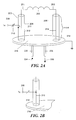
- Figure 2A is a schematic diagram that shows the cascaded structure connected to a cooled plate with RF energy at a first resonant frequency applied to the structure via inductive coupling.
- Figure 2B is a partial schematic diagram that shows the cascaded structure connected to a cooled plate with RF energy at a first resonant frequency applied to the structure via capacitive coupling.
- Figure 3 is a schematic diagram of a cascaded structure in which one leg has been extended to allow an additional resonant frequency to be applied to the structure without disturbing the resonance of the structure at the first resonant frequency.
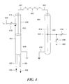
- Figure 4 is a schematic diagram showing another embodiment in which the cooled plate has been replaced by a cylindrical heat exchanger.
- FIG 1 illustrates one embodiment 100 of the invention in which a sample coil 102 is connected to the inner conductors 108 and 110 of two transmission lines 104 and 106.
- the other ends, 112 and 116, of the inner conductors of the transmission lines 104 and 106 are grounded to a common ground plate as indicated schematically by grounds 114 and 118, respectively.
- This structure can then be driven by radio frequency energy by coupling the energy into the resonant structure 100 either capacitive or inductively.
- the cascaded structure 100 will be resonant at many different frequencies of the driving energy and standing waves can be supported within the structure 100.
- the standing waves at three different driving frequencies are shown schematically in Figure 1 by the dotted lines 120, 122 and 124 which represent voltage values within the structure 100.
- a voltage null will occur at the center of the sample coil 102.
- that driving frequency will produce a symmetrical and balanced magnetic field at the center of the sample coil, as desired.
- FIG 2A shows a cascaded structure, such as that shown in Figure 1 , attached to a cooled ground plate 216 in order to cool the sample coil 202.
- sample coil 202 with terminals 201 and 203 is connected to the inner conductors 212 and 214 of two transmission lines 204 and 206, respectively.
- the inner conductors 212 and 214 of the transmission lines 204 and 206 are connected to the common plate 216 which is grounded as indicated at 218.
- Plate 216 may illustratively be hollow so that a cooling fluid can circulate through the plate and cool it.
- the cooling fluid enters the plate 216 via inlet pipe 220 as indicated by arrow 224 and exits the plate 216 via outlet pipe 222 as indicated schematically by arrow 226.
- this structure is driven with radio frequency energy at the 1 H frequency applied to terminal 208 and inductively coupled to the inner conductor 212 of transmission line 204 via the small section 211 that extends parallel to the inner conductor 212.
- Adjustable capacitor 210 matches the impedance of the resonant structure as seen by terminal 208 for efficient RF energy transfer.
- the structure can driven with radio frequency energy at the 1 H frequency applied to terminal 208 and capacitively coupled to the inner conductor 212 of transmission line 204 as shown in the partial schematic view of Figure 2B .
- the cooled ground plate 216 can effectively cool the sample coil 202 down to cryogenic temperatures. Since the sample coil 202 and the inner conductors 212 and 214 of transmission lines 204 and 206 are in direct contact with the grounded and cooled platform 216, the transfer of heat between the sample coil 202 and the plate 216 is very efficient.
- fluid cooling is shown in Figures 2A and 2B for purposes of illustration, the method for cooling the cold plate is not restricted in this structure since the plate 216 is always at ground potential and thus has no effect on the electrical length of the transmission lines 204 and 206 or resonant frequency.
- the cooled plate 216 can be placed outside the probe structure and magnet bore (not shown in Figures 2A and 2B ) to allow a larger, more powerful heat exchanger to be used to cool the plate 216.
- a modified structure allows the introduction of another driving frequency.
- sample coil 302 with terminals 301 and 303 is connected to the inner conductors 312 and 314 of two transmission lines 304 and 306, respectively.
- the inner conductor 312 of the transmission line 304 is connected to a cooled plate 316 which is grounded as indicated at 318.
- Plate 316 may illustratively be hollow so that a cooling fluid can circulate through the plate and cool it.
- the cooling fluid enters the plate 316 via inlet pipe 320 as indicated by arrow 324 and exits the plate 316 via outlet pipe 322 as indicated schematically by arrow 326.
- this structure is driven with radio frequency energy at the 1 H frequency applied to terminal 308 and inductively coupled to the inner conductor 312 of transmission line 304.
- Adjustable capacitor 310 matches the impedance of the resonant structure as seen by terminal 308 for efficient RF energy transfer.
- the structure can driven with radio frequency energy at the 1 H frequency applied to terminal 308 and capacitively coupled to the inner conductor 312 of transmission line 304 along the lines of the structure illustrated in Figure 2B .
- Transmission line 306 is extended to a length of ⁇ H /2 and is open-ended.
- the outer conductor 328 is grounded as indicated at 330.
- transmission line 306 supports a half wavelength standing wave for 1 H frequency with a voltage null half way along its length. Voltage maxima of opposite phases still occur on both ends of the sample coil 302 and, thus, the structure remains balanced at the 1 H frequency.
- the voltage null at the center of transmission line 306 allows RF energy with a second resonant frequency, such as the 13 C frequency, to be coupled into the structure without any effect on the 1 H resonance.
- RF energy at the 13 C frequency at terminal 336 can be coupled to the nodal point 342 on the inner conductor 314 of transmission line 306 by means of adjustable capacitor 334.
- Adjustable capacitor 338 adjusts the frequency of the resonant structure to the 13 C frequency as seen by terminal 336. As nodal point 342 is at ground potential at the 1 H frequency, adjustment of adjustable capacitor 338 has no impact on the 1 H resonance.
- Additional RF energy at other resonance frequencies can be added to the structure either through the same nodal point 342 that the 13 C resonant frequency is added, or by extending the open-ended transmission line 306 by another ⁇ H /2 length to generate another voltage null at the 1 H frequency farther along the line 306 and then coupling the additional RF energy to the structure at the position of the second voltage null. Either method has no impact on 1 H balance or frequency as additions are made at voltage nulls of the 1 H frequency.
- one terminal 301 of the sample coil 302 is connected directly to the inner conductor 312 of one of the transmission lines 304, which, in turn, is in direct contact with the grounded cold platform 316; hence the transfer of heat between the sample coil 302 and the cold platform 316 will also be very efficient.
- Figure 4 shows another embodiment which uses a cylindrical "cold-finger" heat exchanger. Elements in Figure 4 that correspond to elements in Figure 3 have been given corresponding numeral designations. For example, sample coil 402 in Figure 4 corresponds to sample coil 302 in Figure 3 . To shorten the description, elements in Figure 4 that correspond to elements in Figure 3 will not be described further herein.
- the outer conductor 415 of transmission line 404 has been extended and a cylindrical heat exchanger 450 is placed within the extended outer conductor 415.
- the heat exchanger 450 is connected directly to the inner conductor 412 of transmission line 404 in order to cool sample coil 402.
- This compact and efficient cooling arrangement can be implemented in standard bore probes where use of components with large radial dimensions are limited.
- the present invention does not require special materials or construction for the sample coil. Since the sample coil is cooled via direct contact at its terminals rather than through sapphire substrates on the surface of the coil or surrounded by dewars for cryogenic fluids, this method can be used in areas where space is severely restricted, such as within the probe body of a Magic Angle Spinning (MAS) system. Use of transmission lines also provides greater power handling typically required by solid state NMR experiments, a requirement that is particularly challenging at high fields.
- MAS Magic Angle Spinning
Landscapes
- Physics & Mathematics (AREA)
- Condensed Matter Physics & Semiconductors (AREA)
- General Physics & Mathematics (AREA)
- Thermal Sciences (AREA)
- Magnetic Resonance Imaging Apparatus (AREA)
Abstract
Description
- This invention relates to nuclear magnetic resonance probes with sample coils that are cooled by means of cryogenic materials. In conventional nuclear magnetic resonance spectroscopy apparatus, a sample to be analyzed is positioned within a static magnetic field produced within the bore of a high field strength magnet. A probe for detecting magnetic fields is positioned around the sample. The probe includes radio frequency transmitter and receiver coils (which may be the same coil) positioned near the sample for both exciting and detecting magnetic moments in the sample material. Typically, the sample coil is made of copper or other ordinary conductive materials and is arranged to be resonant at the applicable frequencies.
- In many applications, it is advantageous to cool the sample coil. The advantages include an increased Q (quality factor) in the resonator, which in turn, results in a higher signal-to-noise ratio available from the sample. Further, thermal noise generated by copper sample coils can be reduced by cooling the coils. Reduced thermal noise associated with probe circuit improves sensitivity of the spectrometer. A higher signal-to-noise ratio means shorter experimental times and higher throughput. Another advantage is that the sample itself can be more conveniently cooled to cryogenic temperature for certain types of experiments.
- A number of conventional approaches are used to cool the sample coil. One approach is to fabricate the sample coil from a hollow tube instead of a solid wire and to pump a cryogenic cooling fluid through the hollow tube thereby cooling the coil from the inside. This approach has the disadvantage that the production of coils of this type is difficult and the coil geometries that can be attained are limited. In addition, forcing the cryogenic cooling fluid through the tube under pressure may give rise to vibrations that detract from the probe operation.
- In another approach, a multi-walled quartz Dewar flask is used. This flask is constructed as an annulus that is surrounded both on the inside and outside by double walls. The space between the double walls is evacuated. The sample coil fits into the annulus which is then filled with cryogenic cooling fluid. The disadvantage here is that the "filling" factor is poor resulting in poor NMR sensitivity. In addition, the Dewar flask design is difficult and costly to implement.
- In still another prior art approach, a heat exchanger cools a substrate fabricated from a material with high thermal conductivity, but poor electrical conductivity, such as sapphire. The sample coil is in contact with the cooled substrate and is thereby cooled. A disadvantage here is that the substrate material is typically planar and the sample coil must be deposited onto the substrate for good thermal contact. Thus, the sample coil must also be planar and consequently has limited geometry. In addition, the planar coils typically do not have a power handling capability generally required for solid state NMR experiments. A further disadvantage is that the transfer of heat is inefficient due to multi-material contact.
- In another approach, one end of the sample coil is directly in contact with, and cooled by, a cooled platform. However, in this configuration, the magnetic field within sample coil is unbalanced as the cooled platform must be grounded in order not to interfere with the 1H resonance.
- In accordance with the principles of the present invention, the RF source is connected to the sample coil via transmission lines. These transmission lines are arranged to generate one or more nodal points at the 1H frequency. Heat exchangers are then connected directly to the inner conductor of the transmission line at these nodal points. The transmission line inner conductors are in direct contact with the sample coil and efficiently cool the coil to cryogenic temperatures without interfering with the 1H resonance or profile.
- In one embodiment, both ends of the sample coil are connected to the inner conductors of transmission lines. The other ends of both inner conductors are terminated on a cooled plate that is grounded. The transmission line lengths are adjusted so that the cooled plate is at a nodal point at the 1H frequency for both lines. The sample coil is driven by coupling the driving energy, either inductively or capacitively, to the inner conductor of one of the transmission lines.
- In another embodiment, the transmission lines connected between the sample coil and the cooled plate are extended while maintaining the plate at a nodal point so that the plate can be placed outside of the probe structure and the magnet bore. This embodiment allows for a larger, more powerful heat exchanger to cool the plate.
- In still another embodiment, both ends of the sample coil are again connected to the inner conductors of transmission lines. The other end of an inner conductor for one transmission line is terminated on a cooled plate that is grounded. The length of this transmission line is adjusted so that the cooled plate is at a nodal point at the 1H frequency. The other end of the second transmission line is open ended and its length is adjusted so that it supports a half wavelength standing wave at the 1H frequency with a nodal point halfway along its length. The sample coil is driven by coupling the driving energy either inductively or capacitively to the inner conductor of one of the transmission lines. This embodiment has the advantage that a second frequency can be introduced at the latter nodal point without interfering with the 1H frequency balance and resonance.
- In yet another embodiment, the cooled plate is replaced with a cylindrical heat exchanger that fits into the outer conductor of the transmission line.
-
Figure 1 is a schematic diagram of a sample coil cascaded between two transmission lines that illustrates some of the different resonances that the cascaded structure can support. -
Figure 2A is a schematic diagram that shows the cascaded structure connected to a cooled plate with RF energy at a first resonant frequency applied to the structure via inductive coupling. -
Figure 2B is a partial schematic diagram that shows the cascaded structure connected to a cooled plate with RF energy at a first resonant frequency applied to the structure via capacitive coupling. -
Figure 3 is a schematic diagram of a cascaded structure in which one leg has been extended to allow an additional resonant frequency to be applied to the structure without disturbing the resonance of the structure at the first resonant frequency. -
Figure 4 is a schematic diagram showing another embodiment in which the cooled plate has been replaced by a cylindrical heat exchanger. -
Figure 1 illustrates oneembodiment 100 of the invention in which asample coil 102 is connected to theinner conductors transmission lines transmission lines grounds 114 and 118, respectively. This structure can then be driven by radio frequency energy by coupling the energy into theresonant structure 100 either capacitive or inductively. Thecascaded structure 100 will be resonant at many different frequencies of the driving energy and standing waves can be supported within thestructure 100. The standing waves at three different driving frequencies are shown schematically inFigure 1 by thedotted lines structure 100. - At the lowest resonant frequency (n = 1), the standing
wave voltage 120 will have a single maximum at the center of thesample coil 102 and a minimum at theground points wave 122 has voltage maxima of opposite phases, which occur at the twoends sample coil 102, while a voltage null occurs at the center of thesample coil 102. At the next lowest resonant frequency (n = 3) the standingwave 124 has three voltage maxima, which occur somewhere along thetransmission lines sample coil 102. By selecting an appropriate driving frequency, for example n = 2, a voltage null will occur at the center of thesample coil 102. As a result, that driving frequency will produce a symmetrical and balanced magnetic field at the center of the sample coil, as desired. -
Figure 2A shows a cascaded structure, such as that shown inFigure 1 , attached to a cooledground plate 216 in order to cool thesample coil 202. In this structure,sample coil 202 withterminals inner conductors transmission lines inner conductors transmission lines common plate 216 which is grounded as indicated at 218.Plate 216 may illustratively be hollow so that a cooling fluid can circulate through the plate and cool it. The cooling fluid enters theplate 216 viainlet pipe 220 as indicated byarrow 224 and exits theplate 216 viaoutlet pipe 222 as indicated schematically byarrow 226. As illustrated, this structure is driven with radio frequency energy at the 1H frequency applied toterminal 208 and inductively coupled to theinner conductor 212 oftransmission line 204 via thesmall section 211 that extends parallel to theinner conductor 212.Adjustable capacitor 210 matches the impedance of the resonant structure as seen byterminal 208 for efficient RF energy transfer. The lengths oftransmission lines terminal 208 and capacitively coupled to theinner conductor 212 oftransmission line 204 as shown in the partial schematic view ofFigure 2B . - In the structure shown in
Figures 2A and 2B , the cooledground plate 216 can effectively cool thesample coil 202 down to cryogenic temperatures. Since thesample coil 202 and theinner conductors transmission lines platform 216, the transfer of heat between thesample coil 202 and theplate 216 is very efficient. Although fluid cooling is shown inFigures 2A and 2B for purposes of illustration, the method for cooling the cold plate is not restricted in this structure since theplate 216 is always at ground potential and thus has no effect on the electrical length of thetransmission lines - Because the
transmission lines plate 216 can be placed outside the probe structure and magnet bore (not shown inFigures 2A and 2B ) to allow a larger, more powerful heat exchanger to be used to cool theplate 216. - In another embodiment of the invention illustrated in
Figure 3 , a modified structure allows the introduction of another driving frequency. In this structure,sample coil 302 withterminals inner conductors transmission lines inner conductor 312 of thetransmission line 304 is connected to a cooledplate 316 which is grounded as indicated at 318.Plate 316 may illustratively be hollow so that a cooling fluid can circulate through the plate and cool it. The cooling fluid enters theplate 316 viainlet pipe 320 as indicated byarrow 324 and exits theplate 316 viaoutlet pipe 322 as indicated schematically byarrow 326. As illustrated, this structure is driven with radio frequency energy at the 1H frequency applied toterminal 308 and inductively coupled to theinner conductor 312 oftransmission line 304.Adjustable capacitor 310 matches the impedance of the resonant structure as seen byterminal 308 for efficient RF energy transfer. The length oftransmission line 304 is chosen to be an odd multiple of one quarter of the driving energy wavelength (n λH/4, where n = 1, 3, 5, etc.). Alternatively, the structure can driven with radio frequency energy at the 1H frequency applied toterminal 308 and capacitively coupled to theinner conductor 312 oftransmission line 304 along the lines of the structure illustrated inFigure 2B . -
Transmission line 306 is extended to a length of λH/2 and is open-ended. Theouter conductor 328 is grounded as indicated at 330. As extended,transmission line 306 supports a half wavelength standing wave for 1H frequency with a voltage null half way along its length. Voltage maxima of opposite phases still occur on both ends of thesample coil 302 and, thus, the structure remains balanced at the 1H frequency. - The voltage null at the center of
transmission line 306 allows RF energy with a second resonant frequency, such as the 13C frequency, to be coupled into the structure without any effect on the 1H resonance. For example, RF energy at the 13C frequency at terminal 336 can be coupled to thenodal point 342 on theinner conductor 314 oftransmission line 306 by means ofadjustable capacitor 334.Adjustable capacitor 338 adjusts the frequency of the resonant structure to the 13C frequency as seen by terminal 336. Asnodal point 342 is at ground potential at the 1H frequency, adjustment ofadjustable capacitor 338 has no impact on the 1H resonance. - Additional RF energy at other resonance frequencies, such as the 15 N resonance, can be added to the structure either through the same
nodal point 342 that the 13C resonant frequency is added, or by extending the open-endedtransmission line 306 by another λH/2 length to generate another voltage null at the 1H frequency farther along theline 306 and then coupling the additional RF energy to the structure at the position of the second voltage null. Either method has no impact on 1H balance or frequency as additions are made at voltage nulls of the 1H frequency. - In this embodiment, one
terminal 301 of thesample coil 302 is connected directly to theinner conductor 312 of one of thetransmission lines 304, which, in turn, is in direct contact with the groundedcold platform 316; hence the transfer of heat between thesample coil 302 and thecold platform 316 will also be very efficient.Figure 4 shows another embodiment which uses a cylindrical "cold-finger" heat exchanger. Elements inFigure 4 that correspond to elements inFigure 3 have been given corresponding numeral designations. For example,sample coil 402 inFigure 4 corresponds to samplecoil 302 inFigure 3 . To shorten the description, elements inFigure 4 that correspond to elements inFigure 3 will not be described further herein. In theFigure 4 embodiment, theouter conductor 415 oftransmission line 404 has been extended and acylindrical heat exchanger 450 is placed within the extendedouter conductor 415. Theheat exchanger 450 is connected directly to theinner conductor 412 oftransmission line 404 in order to coolsample coil 402. This compact and efficient cooling arrangement can be implemented in standard bore probes where use of components with large radial dimensions are limited. - The present invention does not require special materials or construction for the sample coil. Since the sample coil is cooled via direct contact at its terminals rather than through sapphire substrates on the surface of the coil or surrounded by dewars for cryogenic fluids, this method can be used in areas where space is severely restricted, such as within the probe body of a Magic Angle Spinning (MAS) system. Use of transmission lines also provides greater power handling typically required by solid state NMR experiments, a requirement that is particularly challenging at high fields.
- While the invention has been shown and described with reference to a number of embodiments thereof, it will be recognized by those skilled in the art that various changes in form and detail may be made herein without departing from the spirit and scope of the invention as defined by the appended claims.
- What is claimed is:
Claims (12)
- A nuclear magnetic resonance probe having a cooled sample coil excited by energy having an excitation frequency generated by a source, the probe comprising: a transmission line having an inner conductor connected to the sample coil, wherein the transmission line is arranged to produce a nodal point at the excitation frequency along a length of the inner conductor; and a heat exchanger brought into direct thermal contact with the inner conductor of the transmission line at the nodal point to cool the sample coil.
- The nuclear magnetic resonance probe of claim 1 wherein the sample coil has two terminals and wherein the probe comprises two transmission lines, each transmission line having an inner conductor connected to one terminal of the sample coil, wherein each transmission line is arranged to generate a nodal point at the excitation frequency along a length of its inner conductor and wherein the heat exchanger is brought into direct thermal contact with the inner conductors of both of the transmission lines at the nodal points.
- The nuclear magnetic resonance probe of claim 1 or claim 2 wherein the excitation energy has a wavelength and wherein both the transmission line and the inner conductor have a length substantially equal to one quarter of the wavelength so that the nodal point occurs at an end of the inner conductor that is not connected to the sample coil.
- The nuclear magnetic resonance probe of any of the preceding claims wherein the transmission line has an inner conductor electrically coupled to the source.
- The nuclear magnetic resonance probe of claim 4 wherein the inner conductor is coupled by means of a capacitive coupling to the source.
- The nuclear magnetic resonance probe of claim 4 wherein the inner conductor is coupled by means of an inductive coupling to the source.
- The nuclear magnetic resonance probe of any of the preceding claims wherein the probe further comprises another transmission line having another inner conductor connected to the sample coil, wherein the other transmission line is arranged to produce another nodal point at the excitation frequency along a length of the other inner conductor and wherein the probe further comprises means for coupling the other nodal point to another excitation source having a frequency different from the excitation source.
- The nuclear magnetic resonance probe of claim 7 wherein the excitation energy has a wavelength and wherein the other transmission line and the other inner conductor have a length substantially equal to one half the wavelength.
- The nuclear magnetic resonance probe of any of the preceding claims wherein the heat exchanger is electrically grounded with respect to the source.
- The nuclear magnetic resonance probe of any of the preceding claims wherein the heat exchanger is a flat hollow plate through which cooling fluid is circulated.
- The nuclear magnetic resonance probe of any of the claims 1 to 9 wherein the transmission line has a cylindrical outer conductor and wherein the heat exchanger is cylindrical and shaped to fit inside of the transmission line outer conductor.
- A method for cooling a sample coil of a nuclear magnetic resonance probe according to one of the preceding claims, the method comprising:(a) connecting the inner conductor of the transmission line to the sample coil;(b) adjusting the length of the transmission line to produce a nodal point at the excitation frequency along a length of the inner conductor; and(c) bringing the heat exchanger into direct thermal contact with the inner conductor of the transmission line at the nodal point to cool the sample coil.
Applications Claiming Priority (1)
| Application Number | Priority Date | Filing Date | Title |
|---|---|---|---|
| US11/670,298 US7403007B1 (en) | 2007-02-01 | 2007-02-01 | Nuclear magnetic resonance probe with cooled sample coil |
Publications (2)
| Publication Number | Publication Date |
|---|---|
| EP1953560A2 true EP1953560A2 (en) | 2008-08-06 |
| EP1953560A3 EP1953560A3 (en) | 2009-02-11 |
Family
ID=39473864
Family Applications (1)
| Application Number | Title | Priority Date | Filing Date |
|---|---|---|---|
| EP08001383A Withdrawn EP1953560A3 (en) | 2007-02-01 | 2008-01-25 | Nuclear magnetic resonance probe with cooled sample coil |
Country Status (2)
| Country | Link |
|---|---|
| US (1) | US7403007B1 (en) |
| EP (1) | EP1953560A3 (en) |
Families Citing this family (2)
| Publication number | Priority date | Publication date | Assignee | Title |
|---|---|---|---|---|
| JP5182742B2 (en) * | 2007-08-14 | 2013-04-17 | 株式会社 Jeol Resonance | NMR detector |
| DE102013215918B4 (en) * | 2013-08-12 | 2017-07-27 | Siemens Healthcare Gmbh | Thermostabilization of an antenna arrangement for magnetic resonance tomography |
Family Cites Families (9)
| Publication number | Priority date | Publication date | Assignee | Title |
|---|---|---|---|---|
| US2202700A (en) * | 1937-05-07 | 1940-05-28 | Gen Electric | Transmission apparatus |
| DE4013111C2 (en) * | 1990-04-25 | 1994-05-26 | Spectrospin Ag | RF receiver coil arrangement for NMR spectrometers |
| JPH0427244A (en) * | 1990-05-22 | 1992-01-30 | Toshiba Corp | Broadband exchange network |
| US6231776B1 (en) * | 1995-12-04 | 2001-05-15 | Daniel L. Flamm | Multi-temperature processing |
| DE19722387C2 (en) * | 1997-05-28 | 1999-11-11 | Siemens Ag | Antenna for a magnetic resonance device |
| DE19844895C2 (en) * | 1998-09-30 | 2000-10-05 | Wilfried Hellmuth Bergmann | Probe head for an NMR spectrometer |
| DE19923294C1 (en) * | 1999-05-21 | 2001-02-15 | Bruker Analytik Gmbh | Sample head in which two different nuclear types are excited has high frequency line bridged on half the length with a resonance element |
| JP3886764B2 (en) * | 2001-04-10 | 2007-02-28 | 日本電子株式会社 | Double tuning circuit and probe of nuclear magnetic resonance apparatus |
| DE10361347B4 (en) * | 2003-12-16 | 2012-01-19 | Bruker Biospin Gmbh | Probe for nuclear magnetic resonance measurements |
-
2007
- 2007-02-01 US US11/670,298 patent/US7403007B1/en not_active Expired - Fee Related
-
2008
- 2008-01-25 EP EP08001383A patent/EP1953560A3/en not_active Withdrawn
Also Published As
| Publication number | Publication date |
|---|---|
| US7403007B1 (en) | 2008-07-22 |
| EP1953560A3 (en) | 2009-02-11 |
Similar Documents
| Publication | Publication Date | Title |
|---|---|---|
| JP4170658B2 (en) | RF receiving coil device | |
| JP3066359B2 (en) | Superconducting hybrid resonator for NMR signal reception | |
| US6876200B2 (en) | NMR probe having an inner quadrature detection coil combined with a spiral wound outer coil for irradiation | |
| JP2602494B2 (en) | NMR scanning device | |
| US4751464A (en) | Cavity resonator with improved magnetic field uniformity for high frequency operation and reduced dielectric heating in NMR imaging devices | |
| US7151374B2 (en) | NMR MAS probe with cryogenically cooled critical circuit components | |
| JP5548269B2 (en) | Dual use NMR probe | |
| JP5837954B2 (en) | Active shielded cylindrical gradient coil apparatus with passive RF shield for NMR apparatus | |
| US4641098A (en) | Parallel single turn saddle resonator for nuclear magnetic resonance signal reception | |
| CN104483641B (en) | Electronic-nuclear double-resonance resonator | |
| EP2486416A1 (en) | Dual-mode microwave resonator device and method of electron spin resonance measurement | |
| US4607224A (en) | Double post reentrant cavity for NMR probes | |
| AU768008B2 (en) | Probe head for an NMR spectrometer | |
| US3402346A (en) | Coaxial receiver coil and capacitor structure for probes of uhf gyromagnetic spectrometers | |
| US7187176B2 (en) | NMR probe circuit with nodal impedance bridge | |
| US7403007B1 (en) | Nuclear magnetic resonance probe with cooled sample coil | |
| JP4226853B2 (en) | Equilibrium mode operation of high frequency NMR probes | |
| US7446530B2 (en) | NMR coil having integrated capacitive structures | |
| CN101903789A (en) | Multi-Channel TEM Coils with Auxiliary Decoupling Elements | |
| JP2009103697A (en) | NMR probe head with multiple resonator systems for simultaneous measurement of multiple samples in coupled mode | |
| US7106061B2 (en) | Probe head for nuclear magnetic resonance measurements | |
| JP2010038922A (en) | Nmr spiral rf probe coil pair with low external electric field | |
| US9411028B2 (en) | Multiple resonance sample coil for magic angle spinning NMR probe | |
| JPH0614114B2 (en) | Resonator | |
| US20060082372A1 (en) | Nmr systems employing inverted variable capacitors |
Legal Events
| Date | Code | Title | Description |
|---|---|---|---|
| PUAI | Public reference made under article 153(3) epc to a published international application that has entered the european phase |
Free format text: ORIGINAL CODE: 0009012 |
|
| AK | Designated contracting states |
Kind code of ref document: A2 Designated state(s): AT BE BG CH CY CZ DE DK EE ES FI FR GB GR HR HU IE IS IT LI LT LU LV MC MT NL NO PL PT RO SE SI SK TR |
|
| AX | Request for extension of the european patent |
Extension state: AL BA MK RS |
|
| PUAL | Search report despatched |
Free format text: ORIGINAL CODE: 0009013 |
|
| AK | Designated contracting states |
Kind code of ref document: A3 Designated state(s): AT BE BG CH CY CZ DE DK EE ES FI FR GB GR HR HU IE IS IT LI LT LU LV MC MT NL NO PL PT RO SE SI SK TR |
|
| AX | Request for extension of the european patent |
Extension state: AL BA MK RS |
|
| 17P | Request for examination filed |
Effective date: 20090805 |
|
| 17Q | First examination report despatched |
Effective date: 20090903 |
|
| AKX | Designation fees paid |
Designated state(s): CH DE FR GB LI |
|
| STAA | Information on the status of an ep patent application or granted ep patent |
Free format text: STATUS: THE APPLICATION IS DEEMED TO BE WITHDRAWN |
|
| 18D | Application deemed to be withdrawn |
Effective date: 20100316 |