EP1953427A2 - Control apparatus for transmission mechanism - Google Patents
Control apparatus for transmission mechanism Download PDFInfo
- Publication number
- EP1953427A2 EP1953427A2 EP08250188A EP08250188A EP1953427A2 EP 1953427 A2 EP1953427 A2 EP 1953427A2 EP 08250188 A EP08250188 A EP 08250188A EP 08250188 A EP08250188 A EP 08250188A EP 1953427 A2 EP1953427 A2 EP 1953427A2
- Authority
- EP
- European Patent Office
- Prior art keywords
- electric motor
- transmission ratio
- heat value
- transmission
- control apparatus
- Prior art date
- Legal status (The legal status is an assumption and is not a legal conclusion. Google has not performed a legal analysis and makes no representation as to the accuracy of the status listed.)
- Granted
Links
Images



Classifications
-
- F—MECHANICAL ENGINEERING; LIGHTING; HEATING; WEAPONS; BLASTING
- F16—ENGINEERING ELEMENTS AND UNITS; GENERAL MEASURES FOR PRODUCING AND MAINTAINING EFFECTIVE FUNCTIONING OF MACHINES OR INSTALLATIONS; THERMAL INSULATION IN GENERAL
- F16H—GEARING
- F16H61/00—Control functions within control units of change-speed- or reversing-gearings for conveying rotary motion ; Control of exclusively fluid gearing, friction gearing, gearings with endless flexible members or other particular types of gearing
- F16H61/12—Detecting malfunction or potential malfunction, e.g. fail safe ; Circumventing or fixing failures
-
- F—MECHANICAL ENGINEERING; LIGHTING; HEATING; WEAPONS; BLASTING
- F16—ENGINEERING ELEMENTS AND UNITS; GENERAL MEASURES FOR PRODUCING AND MAINTAINING EFFECTIVE FUNCTIONING OF MACHINES OR INSTALLATIONS; THERMAL INSULATION IN GENERAL
- F16H—GEARING
- F16H63/00—Control outputs from the control unit to change-speed- or reversing-gearings for conveying rotary motion or to other devices than the final output mechanism
- F16H63/02—Final output mechanisms therefor; Actuating means for the final output mechanisms
- F16H63/04—Final output mechanisms therefor; Actuating means for the final output mechanisms a single final output mechanism being moved by a single final actuating mechanism
- F16H63/06—Final output mechanisms therefor; Actuating means for the final output mechanisms a single final output mechanism being moved by a single final actuating mechanism the final output mechanism having an indefinite number of positions
- F16H63/062—Final output mechanisms therefor; Actuating means for the final output mechanisms a single final output mechanism being moved by a single final actuating mechanism the final output mechanism having an indefinite number of positions electric or electro-mechanical actuating means
-
- F—MECHANICAL ENGINEERING; LIGHTING; HEATING; WEAPONS; BLASTING
- F16—ENGINEERING ELEMENTS AND UNITS; GENERAL MEASURES FOR PRODUCING AND MAINTAINING EFFECTIVE FUNCTIONING OF MACHINES OR INSTALLATIONS; THERMAL INSULATION IN GENERAL
- F16H—GEARING
- F16H57/00—General details of gearing
- F16H57/01—Monitoring wear or stress of gearing elements, e.g. for triggering maintenance
- F16H2057/016—Monitoring of overload conditions
-
- F—MECHANICAL ENGINEERING; LIGHTING; HEATING; WEAPONS; BLASTING
- F16—ENGINEERING ELEMENTS AND UNITS; GENERAL MEASURES FOR PRODUCING AND MAINTAINING EFFECTIVE FUNCTIONING OF MACHINES OR INSTALLATIONS; THERMAL INSULATION IN GENERAL
- F16H—GEARING
- F16H59/00—Control inputs to control units of change-speed- or reversing-gearings for conveying rotary motion
- F16H59/68—Inputs being a function of gearing status
- F16H59/70—Inputs being a function of gearing status dependent on the ratio established
- F16H2059/702—Rate of change of gear ratio, e.g. for triggering clutch engagement
-
- F—MECHANICAL ENGINEERING; LIGHTING; HEATING; WEAPONS; BLASTING
- F16—ENGINEERING ELEMENTS AND UNITS; GENERAL MEASURES FOR PRODUCING AND MAINTAINING EFFECTIVE FUNCTIONING OF MACHINES OR INSTALLATIONS; THERMAL INSULATION IN GENERAL
- F16H—GEARING
- F16H35/00—Gearings or mechanisms with other special functional features
- F16H35/10—Arrangements or devices for absorbing overload or preventing damage by overload
-
- Y—GENERAL TAGGING OF NEW TECHNOLOGICAL DEVELOPMENTS; GENERAL TAGGING OF CROSS-SECTIONAL TECHNOLOGIES SPANNING OVER SEVERAL SECTIONS OF THE IPC; TECHNICAL SUBJECTS COVERED BY FORMER USPC CROSS-REFERENCE ART COLLECTIONS [XRACs] AND DIGESTS
- Y10—TECHNICAL SUBJECTS COVERED BY FORMER USPC
- Y10S—TECHNICAL SUBJECTS COVERED BY FORMER USPC CROSS-REFERENCE ART COLLECTIONS [XRACs] AND DIGESTS
- Y10S903/00—Hybrid electric vehicles, HEVS
- Y10S903/902—Prime movers comprising electrical and internal combustion motors
- Y10S903/903—Prime movers comprising electrical and internal combustion motors having energy storing means, e.g. battery, capacitor
- Y10S903/904—Component specially adapted for hev
- Y10S903/915—Specific drive or transmission adapted for hev
- Y10S903/917—Specific drive or transmission adapted for hev with transmission for changing gear ratio
Definitions
- the electric motor In a typical ECVT, the electric motor is driven in reverse relatively often due to changes in transmission ratio. As a result, a relatively large amount of heat is generated by the electric motor, leading to temperature rise in the electric motor and its driving circuit, and to the possibility of deterioration in the motor performance.
- the transmission mechanism 20a has a primary sheave 21, a secondary sheave 22, and a V belt 23.
- the V belt 23 is run around the primary sheave 21 and the secondary sheave 22.
- the V belt has a generally V-shape cross section.
- the movable sheave half 21b is provided with a cylindrical boss part 21d through which the crankshaft 11 passes.
- a cylindrical slider 24 is secured to the inside of the boss part 21d.
- the slider 24 and the movable sheave half 21b form an integral body to be movable in the axial direction of the crankshaft 11. Therefore, the groove width of the belt groove 21c is variable.
- the ECU 7 is also connected to a primary sheave revolution sensor 43, a secondary sheave revolution sensor 41, and a vehicle speed sensor 42.
- the primary sheave revolution sensor 43 detects the revolution of the primary sheave 21 and outputs a sheave revolution signal to the ECU 7.
- the secondary sheave revolution sensor 41 detects the revolution of the secondary sheave 22 and outputs a sheave revolution signal to the ECU 7.
- the vehicle speed sensor 42 detects the revolution of the rear wheel 3 and outputs a vehicle speed signal according to the detected revolution to the ECU 7.
- step S3 operation of the electric motor 30 is restricted or stopped.
Landscapes
- Engineering & Computer Science (AREA)
- General Engineering & Computer Science (AREA)
- Mechanical Engineering (AREA)
- Control Of Transmission Device (AREA)
- Friction Gearing (AREA)
Abstract
Description
- This invention relates to: a control apparatus for a transmission mechanism, a transmission, a vehicle provided with the transmission, a method of controlling the transmission mechanism, and a method of estimating the heat value of an electric motor. In particular, this invention relates to a control apparatus for an electronically controlled transmission mechanism with its transmission ratio made variable with an electric motor, an electronically controlled transmission with its transmission ratio made variable with an electric motor, a vehicle provided with such a transmission, a method of controlling the electronically controlled transmission mechanism with its transmission ratio made variable with the electric motor, and a method of estimating the heat value of the electric motor in the electronically controlled transmission mechanism with its transmission ratio made variable with the electric motor.
- A continuously variable transmission is conventionally known with which the transmission ratio may be changed continuously using an electric motor (hereinafter referred to as ECVT, in full: electronically, continuously variable transmission). An ECVT is disclosed in, for example,
JP-A-2004-19740 - In a typical ECVT, the electric motor is driven in reverse relatively often due to changes in transmission ratio. As a result, a relatively large amount of heat is generated by the electric motor, leading to temperature rise in the electric motor and its driving circuit, and to the possibility of deterioration in the motor performance.
- Therefore, it is preferable to monitor the motor temperature or the heat value so that the motor temperature does not exceed a permissible use temperature range. For example, a method of estimating the motor temperature is conceivable in which temperature sensors are provided on the motor, its driving circuit etc. Because the heat value of the motor is in proportion to the square of the current flowing through the motor, another conceivable method of estimating the heat value of the motor is to provide a current sensor to measure the current flowing through the motor, and estimate the heat value of the motor from the measured current.
- The methods mentioned above, however, require separate temperature sensor and current sensor to be provided. As a result, constitution and control of the ECVT become undesirably complicated.
- This invention has been made in view of the above points. Therefore, an object of the invention is to provide a transmission that makes it possible to estimate the heat value of the electric motor with a simple constitution.
- Incidentally, while the problems to be solved are explained here using the ECVT as an example, the problems to be solved are also true of transmissions in general that change transmission ratio using an electric motor.
- The control apparatus of to the invention is a control apparatus of a continuously variable transmission mechanism made up of an input shaft, an output shaft, and an electric motor for changing continuously the transmission ratio between the input shaft and output shaft. The control apparatus of the invention estimates the heat value of the electric motor based on the rate of change in the transmission ratio.
- The continuously variable transmission of the invention is made up of a continuously variable transmission mechanism, and a control section. The continuously variable transmission mechanism includes an input shaft, an output shaft, and an electric motor. The electric motor changes the transmission ratio continuously between the input shaft and the output shaft. The control section estimates the heat value of the electric motor on the basis of the rate of change in the transmission ratio.
- The vehicle of the invention includes the continuously variable transmission of the invention.
- The control method of the invention is a method of controlling the continuously variable transmission mechanism made up of an input shaft, an output shaft, and an electric motor for changing continuously transmission ratio between the input shaft and output shaft. With the controlling method of the invention, the heat value of the electric motor is estimated from the rate of change in the transmission ratio.
- The method of estimating the heat value of the electric motor of the invention is a method of estimating the heat value of the electric motor in a continuously variable transmission made up of an input shaft, an output shaft, and an electric motor for changing continuously the transmission ratio between the input shaft and output shaft. According to the method of estimating the heat value of the electric motor of the invention, the heat value of the electric motor is estimated from the rate of change in the transmission ratio.
- Aspects of the present invention are set forth in the independent claims.
- Preferred features of the present invention are set forth in the dependent claims.
- The present invention makes it possible to bring about a transmission in which the heat value of the electric motor is estimated with a simple constitution.
- These and other aspects of the present invention will now be described, by way of example only, with reference to the accompanying drawings, in which:
-
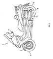
Fig. 1 is a side view of a motorcycle to which the invention is applied; -
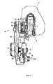
Fig. 2 is a sectional view of an engine unit; -
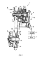
Fig. 3 is a partial sectional view, showing the constitution of an ECVT; -
Fig. 4 is a block diagram, representing a control system of the motorcycle; -
Fig. 5 is a block diagram, representing sheave position control; -
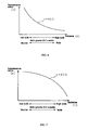
Fig. 6 is a graph of the function r = f(1) as an example; -
Fig. 7 is a graph of the function r = f(1) as another example; -
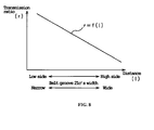
Fig. 8 is a graph of the function r = f(1) as still another example; and -
Fig. 9 is a flowchart illustrating the method of estimating the heat value of the electric motor and the method of controlling the electric motor. - The inventor as a result of eager study found a correlation between the heat value of the electric motor and the rate of change in the transmission ratio and came to fabricate this embodiment.
- An example of a preferable embodiment of the invention is described in detail below using a
motorcycle 1 as an example. While this embodiment is described using the so-called scooter type ofmotorcycle 1 as an example, the vehicle of the invention is not limited to the scooter type of motorcycle. The vehicle of the invention may be other than the scooter type of motorcycle. Specifically, the two-wheeled vehicle of the invention may be an off-road type, motorcycle type, scooter type, or a so-called moped type. Further, the vehicle of the invention may be straddle type of vehicle other than the motorcycle. Specifically, the vehicle related to the invention may be, for example, an ATV (all-terrain vehicle). Furthermore, the vehicle of the invention may be other than the straddle type of vehicle such as a four-wheeled vehicle. -
Fig. 1 is a side view of themotorcycle 1. Themotorcycle 1 is provided with a vehicle body frame (not shown). Anengine unit 2 is mounted on the vehicle body frame. Arear wheel 3 is attached to the rear part of theengine unit 2. In this embodiment, therear wheel 3 is the driving wheel driven with theengine unit 2. - The vehicle body frame has a head pipe (not shown) extending downward from
handlebars 4. Afront fork 5 is connected to the lower end part of the head pipe. A front wheel 6 is attached for rotation to the lower end part of thefront fork 5. The front wheel 6 is not connected to theengine unit 2 and is a wheel for free rotation. - The constitution of the
engine unit 2 will now be described with reference toFigs. 2 and3 . - As shown in
Figs. 2 and3 , theengine unit 2 includes an (internal combustion)engine 10 and atransmission 20. In this embodiment, theengine 10 is described as a forced air-cooled, four-stroke cycle engine. However, theengine 10 may be of other types. For example, theengine 10 may be of a water-cooled type. Also theengine 10 may be of a two-stroke cycle type. - As shown in
Fig. 3 , theengine 10 has acrankshaft 11. Asleeve 12 is brought in spline engagement with the outer circumference of thecrankshaft 11. Thesleeve 12 is supported for rotation by ahousing 14 through abearing 13. A one-way clutch 31 connected to anelectric motor 30 is attached around thesleeve 12. - The
transmission 20 is made up of atransmission mechanism 20a, and an ECU 7 as a control section for controlling thetransmission mechanism 20a. In this embodiment, thetransmission mechanism 20a is described as a belt type of ECVT as an example. The belt of ECVT may be a resin belt, a metal belt, or any other suitable belt. Further, thetransmission mechanism 20a is not limited to the belt type of ECVT. Thetransmission mechanism 20a may be for example a toroidal type of ECVT. Further, thetransmission mechanism 20a may be of other than ECVT, of electronically controlled type. - The
transmission mechanism 20a has aprimary sheave 21, asecondary sheave 22, and aV belt 23. TheV belt 23 is run around theprimary sheave 21 and thesecondary sheave 22. The V belt has a generally V-shape cross section. - The
primary sheave 21 rotates integrally with thecrankshaft 11. Theprimary sheave 21 consists of astationary sheave half 21a and amovable sheave half 21b. Thestationary sheave half 21a is secured to one end of thecrankshaft 11. Themovable sheave half 21b is disposed to oppose thestationary sheave half 21a. Themovable sheave half 21b is movable in the axial direction of thecrankshaft 11. Opposing surfaces of thestationary sheave half 21a and themovable sheave half 21b form abelt groove 21c in which theV belt 23 runs. Thebelt groove 21c becomes wider toward radially outer side of theprimary sheave 21. - As shown in
Fig. 3 , themovable sheave half 21b is provided with a cylindrical boss part 21d through which thecrankshaft 11 passes. Acylindrical slider 24 is secured to the inside of the boss part 21d. Theslider 24 and themovable sheave half 21b form an integral body to be movable in the axial direction of thecrankshaft 11. Therefore, the groove width of thebelt groove 21c is variable. - The groove width of the
belt groove 21c of theprimary sheave 21 is varied as themovable sheave half 21b is driven in the axial direction of thecrankshaft 11 by theelectric motor 30. In this embodiment, theelectric motor 30 is assumed to be driven by PWM (pulse width modulation). However, the driving type of theelectric motor 30 is not restrictive. Themotor 30 may be a stepper motor. - The
secondary sheave 22 is arranged behind theprimary sheave 21. Thesecondary sheave 22 is attached through a centrifugal clutch 25 to a drivenshaft 27. In detail, thesecondary sheave 22 is made up of astationary sheave half 22a and amovable sheave half 22b. Themovable sheave half 22b opposes thestationary sheave half 22a. Themovable sheave half 22b is movable in the axial direction of the drivenshaft 27. Opposing surfaces of thestationary sheave half 22a and themovable sheave half 22b form abelt groove 22c in which theV belt 23 runs. Thebelt groove 22c becomes wider toward a radially outer side of thesecondary sheave 22. - The
movable sheave half 22b is biased by aspring 26 in the direction for decreasing the groove width of thebelt groove 22c. Therefore, as theelectric motor 30 is driven, and the groove width of thebelt groove 21c of theprimary sheave 21 decreases, the curve radius of theV belt 23 on theprimary sheave 21 increases, and theV belt 23 on thesecondary sheave 22 side is drawn radially inward. As a result, themovable sheave half 22b moves against the force of thespring 26 in the direction for widening thebelt groove 22c. As a result, the curve radius of theV belt 23 running on thesecondary sheave 22 decreases, so that the transmission ratio of thetransmission mechanism 20a varies. - The centrifugal clutch 25 is engaged or disengaged according to the revolution of the
stationary sheave half 22a. That is, when the revolution of thestationary sheave half 22a is below a specified value, the centrifugal clutch 25 is disengaged. Therefore, the rotation of thestationary sheave half 22a is not transmitted to the drivenshaft 27. On the other hand, when revolution of thestationary sheave half 22a reaches or exceeds a specified value, the centrifugal clutch 25 is engaged, so that the rotation of thestationary sheave half 22a is transmitted to the drivenshaft 27. - The driven
shaft 27 is connected to aspeed reduction mechanism 28. The drivenshaft 27 is connected though thespeed reduction mechanism 28 to awheel shaft 29. To thewheel shaft 29 is attached therear wheel 3. Thus, as the drivenshaft 27 rotates, therear wheel 3 rotates together with thewheel shaft 29. - Details of the control system for the
motorcycle 1 will now be described with reference toFig. 4 . - As shown in
Fig. 4 , the ECU 7 is connected to asheave position sensor 40. Thesheave position sensor 40 detects the position of themovable sheave half 21b of theprimary sheave 21 relative to thestationary sheave half 21a thereof. In other words, it detects the distance (1) between thestationary sheave half 21a and themovable sheave half 21b in the axial direction of thecrankshaft 11. Thesheave position sensor 40 outputs the detected distance (1) as a detected sheave position signal to the ECU 7. Here, thesheave position sensor 40 may be constituted for example with a potentiometer or the like. - The ECU 7 is also connected to a primary sheave revolution sensor 43, a secondary sheave revolution sensor 41, and a vehicle speed sensor 42. The primary sheave revolution sensor 43 detects the revolution of the
primary sheave 21 and outputs a sheave revolution signal to the ECU 7. The secondary sheave revolution sensor 41 detects the revolution of thesecondary sheave 22 and outputs a sheave revolution signal to the ECU 7. The vehicle speed sensor 42 detects the revolution of therear wheel 3 and outputs a vehicle speed signal according to the detected revolution to the ECU 7. - The ECU 7 is connected to a handlebar switch attached to the
steering handlebars 4. The handlebar switch, when operated by a rider, outputs a handlebar switch signal. - A throttle
opening degree sensor 18a outputs a throttle opening degree signal to the ECU 7. - The ECU 7 performs feedback control of the sheave position of the
movable sheave half 21b of theprimary sheave 21 according to the vehicle speed signal, etc. In other words, the ECU 7 performs feedback control of the distance (1) according to the vehicle speed signal, etc. Specifically, as shown inFig. 5 , a target transmission ratio is determined in the ECU 7 from the throttle opening degree and the vehicle speed. The ECU 7 calculates from the determined target transmission ratio the sheave target position. In other words, the ECU 7 calculates from the determined target transmission ratio thetarget distance 1 between themovable sheave half 21b and thestationary sheave half 21a. In order to move themovable sheave half 21b to the sheave target position, the ECU 7 outputs a pulse width modulation signal (PWM signal) corresponding to the present position of themovable sheave half 21b and the sheave target position to adriving circuit 8 shown inFig. 4 . The drivingcircuit 8 applies an impulse voltage corresponding to the PWM signal to theelectric motor 30. As a result, themovable sheave half 21b is driven to adjust the transmission ratio. - The method of estimating the heat value of the
electric motor 30 will now be described. First, before describing a method of estimating the heat value of theelectric motor 30 in detail, the principle of the method is described. - The inventor, as a result of eager study, found a correlation between the heat value of the
electric motor 30 and the rate of change in the transmission ratio of thetransmission mechanism 20a. Specifically, the inventor came to the idea of correlation between the heat amount and the rate of change in the transmission ratio of thetransmission mechanism 20a as a result of the findings enumerated below: - 1) The heat value of the
electric motor 30 is in linear correlation to the square of part of effective voltage applied to theelectric motor 30 that contributes to the heat generation by theelectric motor 30. - 2) The amount of voltage contributing to the heat generation by the
electric motor 30 is determined by subtracting the induced voltage for moving themovable sheave half 21b from the effective voltage applied to theelectric motor 30. - 3) The induced voltage for moving the
movable sheave half 21b is in linear correlation to the rate of change in the transmission ratio of thetransmission mechanism 20a. - From the above findings by the inventor, the heat value of the
electric motor 30 may be estimated using the equation (1) below:
where
β : a constant.
VA: effective voltage applied to theelectric motor 30. dr/dt: rate of change in the transmission ratio of thetransmission mechanism 20a.
α : a constant, or a factor expressed with the following equation (3a) or (3b):

where
f(1): a function ofdistance 1 representing the transmission ratio.
r: transmission ratio.
g(r): a function of transmission ratio r, or an inverse function of the above function f(1). - In this embodiment, the above equations (3a) and (3b) are equal to each other.
- In this embodiment, because the
electric motor 30 is controlled as described above by pulse width modulation, VA in the above equation (1) is expressed with the equation (2) below:
Vp: magnitude of pulse voltage applied to theelectric motor 30.
DUTY: duty ratio of pulse voltage applied to theelectric motor 30. - Therefore, the equation (1) may be transformed from the equation (2) into the following equation (4):

β : a constant.
Vp: magnitude of pulse voltage applied to theelectric motor 30.
DUTY: duty ratio of pulse voltage applied to theelectric motor 30.
α : a constant, or a factor expressed with the following equation (3a) or (3b):

f(1): a function ofdistance 1 representing the transmission ratio.
r: transmission ratio.
g(r): a function of transmission ratio r, or an inverse function of the above function f(1). - According to this embodiment, the heat value of the
electric motor 30 is estimated as described below using equation (4) above. The rate of change in the transmission ratio of thetransmission mechanism 20a is calculated from thedistance 1 detected with thesheave position sensor 40. - In equation (4) above, the function r = f(1) is determined according to the shapes of the
belt groove 21c and thebelt groove 22c. For example as shown inFig. 6 , the function r = f(1) may be a downward convex exponential function. In other words, the function r = f(1) may be set so that the change in the transmission ratio r relative to the change in thedistance 1 becomes gentler as thedistance 1 increases and the width of thebelt groove 21c increases. In other words, the function r = f(1) may be set so that the change in the transmission ratio r relative to the change in thedistance 1 becomes gentler as the transmission ratio changes toward the high side. In this case, the value α in equation (4) tends to be smaller as thedistance 1 increases. - Alternatively, the function r = f(1) may be an upward convex exponential function as shown in
Fig. 7 as an example. In other words, function r = f (1) may be set so that the change in the transmission ratio r relative to the change in thedistance 1 becomes steeper as thedistance 1 increases and the width of thebelt groove 21c increases. In other words, the function r = f(1) may be set so that the change in the transmission ratio r relative to the change in thedistance 1 becomes steeper as the transmission ratio changes toward the high side. In this case, the value α in equation (4) tends to be greater as thedistance 1 increases. - Further, the function r = f(1) may also be linear as shown in
Fig. 8 as an example. In other words, the function r = f(1) may be set to be constant irrespective of the values of thedistance 1 and thebelt groove 21c. In other words, the function r = f(1) may be set to be constant irrespective of the transmission ratio. In this case, the value α in equation (4) remains constant irrespective of thedistance 1. That is, α is a constant. -
Fig. 9 is a flowchart representing the method of estimating the heat value of theelectric motor 30 and method of controlling theelectric motor 30. As shown inFig. 9 , the heat value of theelectric motor 30 is estimated in step S1. Specifically, in step S1, the heat value of theelectric motor 30 is estimated using equation (4) above. - Next, in step S2, a determination is made whether or not the estimated heat value of the
electric motor 30 in step S1 is greater than a specified value. Because the heat value of theelectric motor 30 is in correlation to the temperature of theelectric motor 30, in general, the greater the heat value of theelectric motor 30, the higher the temperature of theelectric motor 30 accordingly. Therefore, it is possible to determine whether or not the temperature of theelectric motor 30 is above the specified value, or alternatively, according to the determination in step S2 "whether or not the estimated heat value of theelectric motor 30 is greater than a specified heat value." In other words, whether or not the temperature of theelectric motor 30 is above the specified value is essentially determined in step S2. - Incidentally, the "specified heat value" in step S2 may be appropriately specified according to the characteristics of the
electric motor 30 and the drivingcircuit 8. For example the "specified heat value" may be specified to be a value at which deterioration in performance is estimated to occur in theelectric motor 30 and the drivingcircuit 8. In other words, the "specified heat value" may be specified to be a value above which the temperature of theelectric motor 30 is estimated to exceed a permissible use temperature limit. - When the heat value of the
electric motor 30 is determined to be greater than the specified heat value in step S2 as shown inFig. 9 , the process proceeds to step S3. In step S3, operation of theelectric motor 30 is restricted or stopped. - After that, the process proceeds to step S4 to determine whether or not a specified period of time has lapsed after the operation of the
electric motor 30 was restricted or stopped. In other words, it is determined in step S4 whether or not a specified period of time has lapsed after the restriction or stop of the operation of theelectric motor 30 and whether or not the temperature of theelectric motor 30 has lowered sufficiently. Here, the "specified period of time" may be specified for example to be a period of time taken for lowering the temperature of theelectric motor 30 sufficiently. Therefore, the period of time taken for lowering the temperature of theelectric motor 30 sufficiently is different according to the contents of the control made in step S3. For example, when the operation of theelectric motor 30 is stopped, the temperature of theelectric motor 30 lowers relatively quickly, so the "specified period of time" may be specified to be relatively short. - When it is determined in step S4 that the specified period of time has not lapsed after restricting or stopping the operation of the
electric motor 30, the process returns to step S4. On the other hand, when it is determined in step S4 that the specified period of time has lapsed after the restriction or stop of the operation of theelectric motor 30, the process proceeds to step S5, and the operation of theelectric motor 30 is restored to the state before the restriction or stop made in step S3. - In contrast to the above, when it is determined in step S2 that the heat value of the
electric motor 30 is less than the specified value, the process ends without performing steps S3 through S5. - Incidentally, the control of restricting or stopping the operation of the
electric motor 30 in step S3 is not limited to a specific one as long as the control is performed so that the heat value of theelectric motor 30 becomes smaller than that in normal operation of theelectric motor 30. For example, the operation of theelectric motor 30 may be stopped. In other words, changing the transmission ratio may be restricted. Further, for example, at least one of the upper limit of the revolution and the upper limit of the torque of theelectric motor 30 may be lowered. In other words, the upper limit of the rate of change in the transmission ratio of thetransmission mechanism 20a may be lowered. That is, in the case of a control in which the rate of change in the transmission ratio of thetransmission mechanism 20a exceeds its upper limit, it may be made that the rate of change in the transmission ratio is restricted down to the upper limit speed. Further, for example, a permissible revolution range of theelectric motor 30 may be narrowed. In other words, a permissible range of the transmission ratio of thetransmission mechanism 20a may be narrowed. Further for example it is possible to make ineffective only the action that changes the transmission ratio suddenly like a kick-down action. Specifically, it may be adapted that the ECU 7 does not output pulse width modulation signals of great duty ratios (Refer toFig. 5 ). - With this embodiment as described above, the heat value of the
electric motor 30 is estimated from the rate of change in the transmission ratio of thetransmission mechanism 20a. Thus, the heat value of theelectric motor 30 is estimated using the rate of change in the transmission ratio obtained by differentiating with respect to time the transmission ratio detected with the sensor normally provided in thetransmission mechanism 20a for measuring the transmission ratio. Specifically in this embodiment the heat value of theelectric motor 30 is estimated using the rate of change in the transmission ratio calculated from thedistance 1 detected with thesheave position sensor 40. Therefore, it is possible to estimate the heat value of theelectric motor 30 with inexpensive, simple constitution without using additional sensors such as temperature sensors and current sensors. - When the heat value of the
electric motor 30 exceeds the specified heat value and the temperature of theelectric motor 30 is estimated to have risen beyond the permissible use temperature range of theelectric motor 30, the operation of theelectric motor 30 is restricted or stopped. This restricts theelectric motor 30 from heating up above the permissible use temperature range. As a result, deterioration in performance and damage of theelectric motor 30 and the drivingcircuit 8 are effectively restricted. - In particular with the method of restricting the operation of the
electric motor 30 by lowering the upper limit of the rate of change in the transmission ratio of thetransmission mechanism 20a, although the change in the transmission ratio becomes slow, is preferable because the transmission ratio is changed according to the vehicle speed and so the maneuver of themotorcycle 1 is less affected. - Also with this embodiment, when a specified period of time lapses after the restriction or the stop of operation of the
electric motor 30, the operation of theelectric motor 30 is restored to the state before the restriction or the stop. Therefore, when the specified period of time lapses after the restriction or the stop of operation of theelectric motor 30, and the temperature of theelectric motor 30 is estimated to have lowered within the permissible use temperature range, the operation of theelectric motor 30 becomes normal. In this way, it is possible to restrict or stop the operation of theelectric motor 30 only when required, otherwise operate theelectric motor 30 swiftly, and change the transmission ratio at relatively high speeds. As a result, high quality of driveability is realized. - The
transmission mechanism 20a is not limited to the belt type of ECVT. For example, thetransmission mechanism 20a may be toroidal type of ECVT. Further, thetransmission mechanism 20a may be other than the CVT. That is, there is no restriction to the type oftransmission mechanism 20a as long as it is electronically controlled. However, because reverse drive of theelectric motor 30 occurs frequently in the ECVT, this invention is especially effective for the ECVT. - In the case the
motorcycle 1 uses theelectric motor 30 controlled by PWM and thetransmission mechanism 20a is the belt type of ECVT like in the embodiment above, the heat value of theelectric motor 30 may be estimated using equation (4) above. In the case, for example, theelectric motor 30 is not controlled by PWM or thetransmission mechanism 20a is not the belt type of ECVT, the heat value of theelectric motor 30 can be estimated using a more common equation, equation (1). In that case, as a matter of course, equation (1) may be transformed according to thetransmission mechanism 20a. In other words, equation (1) can be applied commonly to anytransmission mechanism 20a as long as it is electronically controlled to change the transmission ratio using an electric motor. Using equation (1) makes it possible to estimate the heat value of theelectric motor 30 irrespective of the type of thetransmission mechanism 20a that is electronically controlled. Therefore, this embodiment places no restriction on the type oftransmission mechanism 20a as long as the transmission mechanism is electronically controlled using an electric motor. - The vehicle of this invention may be other than the scooter type of motorcycle. The vehicle of the invention may be an off-road type, motorcycle type, scooter type, or a so-called moped type. Further, the vehicle of the invention may be a straddle type of vehicle other than the motorcycle. Specifically, the vehicle of the invention may be, for example, an ATV (all-terrain vehicle). Furthermore, the vehicle of the invention may be other than the straddle type of vehicle such as a four-wheeled vehicle.
- While the above embodiment is described as a preferable example using the
motorcycle 1 provided with theinternal combustion engine 10, the vehicle of the invention may be any vehicle provided with a driving source other than the engine. For example, the vehicle of the invention may be provided with an electric motor in place of, or in combination with, theengine 10. - The
electric motor 30 is not limited to one controlled by PWM. For example, theelectric motor 30 may be one controlled by pulse amplitude modulation (PAM). Themotor 30 may be a stepper motor. - The term "specified heat value" in step S2 may be appropriately specified according to the characteristics of the
electric motor 30 and the drivingcircuit 8. For example, the "specified heat value" may be specified to a value above which deterioration in performance of theelectric motor 30 and the drivingcircuit 8 is estimated to occur. In other words, the "specified heat value" may be specified to a value above which it is estimated that the temperature of theelectric motor 30 exceeds a permissible use temperature range of theelectric motor 30. - The "specified period of time" in step S4 may be appropriately specified according to the details of the control performed in step S3 for restricting or stopping the operation of the
electric motor 30. For example, the "specified period of time" in step S4 may be specified to a period of time after the restriction or stop of operation of theelectric motor 30 in which the temperature of theelectric motor 30 can be determined to have lowered well into the permissible use temperature range of theelectric motor 30. - The phrase "the distance between the
movable sheave half 22b and thestationary sheave half 22a" is the distance between a specific point on themovable sheave half 22b and a specific point on thestationary sheave half 22a. Those specific points may be arbitrarily set as long as each of them is determined with a single meaning. For example as shown inFig. 3 , "the distance between themovable sheave half 22b and thestationary sheave half 22a" may be defined to be the distance between the outermost radial end of themovable sheave half 22b and the outermost radial end of thestationary sheave half 22a. - The term "the magnitude of the pulse voltage" means the magnitude of the input pulse voltage.
- The term "effective voltage" means the voltage obtained by multiplying the input pulse voltage by duty ratio.
- This invention is effective in vehicles provided with an ECVT.
-
- 1:
- motorcycle
- 2:
- engine unit
- 7:
- ECU
- 8:
- driving circuit
- 10:
- engine
- 11:
- crankshaft
- 20:
- transmission
- 20a:
- transmission mechanism
- 21:
- primary sheave
- 21a:
- stationary sheave half
- 21b:
- movable sheave half
- 21c:
- belt groove
- 22:
- secondary sheave
- 22a:
- stationary sheave half
- 22b:
- movable sheave half
- 22c:
- belt groove
- 23:
- V belt
- 27:
- driven shaft
- 28:
- speed reduction mechanism
- 29:
- wheel shaft
- 30:
- electric motor
- 40:
- sheave position sensor
- 41:
- secondary sheave revolution sensor
- 42:
- vehicle speed sensor
- 43:
- primary sheave revolution sensor
Claims (15)
- A control apparatus for a transmission mechanism (20a), the transmission mechanism comprising:an input shaft (11),an output shaft (27), andan electric motor (30) for changing a transmission ratio between the input shaft (11) and output shaft (27),wherein the control apparatus is adapted to estimate a heat value of the electric motor (30) from a rate of change in the transmission ratio.
- The control apparatus of Claim 1, wherein operation of the electric motor (30) is restricted or stopped when the estimated heat value of the electric motor (30) reaches or exceeds a specified value.
- The control apparatus of Claim 2, wherein the operation of the electric motor (30) is restricted by lowering an upper limit of rate of change in the transmission ratio when the estimated heat value of the electric motor (30) reaches or exceeds a specified value.
- The control apparatus of Claim 2 or 3, wherein the operation of the electric motor (30) is restricted by narrowing a permissible range of the transmission ratio when the estimated heat value of the electric motor (30) reaches or exceeds a specified value.
- The control apparatus of Claim 2, 3 or 4, wherein the operation of the electric motor (30) is resumed after a lapse of a specified time from the restriction or stop of the electric motor (30) operation.
- The control apparatus of any preceding Claim, wherein the heat value of the electric motor (30) is estimated using the following equation (1):

where
β : a constant
VA: effective voltage applied to the electric motor
dr/dt: rate of change in the transmission ratio
α : a constant that is expressed with the following equation (3b) :
where
g(r): a function of transmission ratio r. - The control apparatus of Claim 6, further comprising a driving circuit (8) for applying an impulse voltage to the electric motor (30) and meeting the following equation (2):

where
Vp: magnitude of the impulse voltage
DUTY: duty ratio of the impulse voltage. - The control apparatus of any preceding Claim,
wherein the transmission mechanism (20a) comprises:a primary sheave (21) provided on the input shaft (11),a secondary sheave (22) provided on the output shaft (27), anda V belt (23) routed around the primary and secondary sheaves (21, 22),wherein the primary sheave (21) comprises:a stationary sheave half (21a), anda movable sheave half (21b), opposing the stationary sheave half (21a), displaceable in the input shaft axis direction, and constituting together with the stationary sheave half (21a) a V groove (21c) through which the V belt (23) is routed,wherein the electric motor (30) is adapted to change the transmission ratio by displacing the movable sheave half (21b) relative to the stationary sheave half (21a) so as to change a width of the V groove (21c), andthe heat value of the electric motor (30) is estimated using the following equation (1):
where
β : a constant
VA: effective voltage applied to the electric motor
dr/dt: rate of change in the transmission ratio
α : a constant that is expressed with the following equation 3(a) or (3b):

where
f(1): a function of 1 representing the transmission ratio
g(r): a function of transmission ratio, an inverse function of the function f(1). - The control apparatus of Claim 8,
where α increases with the increase in the distance 1. - The control apparatus of Claim 8,
where α decreases with the increase in the distance 1. - The control apparatus of Claim 8,
where α is constant irrespective of the distance 1. - A transmission (20) comprising:a transmission mechanism (20a) comprising: an input shaft (11), an output shaft (27), and an electric motor (30) for changing a transmission ratio between the input shaft (11) and the output shaft (27); anda control section for estimating a heat value of the electric motor (30) based on the rate of change in the transmission ratio.
- A vehicle (1) comprising a transmission (20) according to Claim 12.
- A control method for a transmission mechanism (20a), the transmission mechanism (20a) comprising:an input shaft (11),an output shaft (27), andan electric motor (30) for changing a transmission ratio between the input shaft (11) and the output shaft (27),the control method comprising: estimating a heat value of the electric motor (30) based on a rate of change in the transmission ratio.
- A method of estimating a heat value of an electric motor (30) in a transmission mechanism (20a), the transmission mechanism (20a) comprising:an input shaft (11),an output shaft (27), andan electric motor (30) for changing a transmission ratio between the input shaft (11) and the output shaft (27),the method comprising the step of estimating the heat value of the electric motor (30) based on a rate of change in the transmission ratio.
Applications Claiming Priority (2)
| Application Number | Priority Date | Filing Date | Title |
|---|---|---|---|
| JP2007022217 | 2007-01-31 | ||
| JP2007277115A JP5406444B2 (en) | 2007-01-31 | 2007-10-25 | Transmission mechanism control device, transmission device, vehicle equipped with the same, transmission mechanism control method, and motor heat generation amount estimation method in transmission mechanism |
Publications (3)
| Publication Number | Publication Date |
|---|---|
| EP1953427A2 true EP1953427A2 (en) | 2008-08-06 |
| EP1953427A3 EP1953427A3 (en) | 2011-03-02 |
| EP1953427B1 EP1953427B1 (en) | 2011-12-21 |
Family
ID=39341451
Family Applications (1)
| Application Number | Title | Priority Date | Filing Date |
|---|---|---|---|
| EP08250188A Active EP1953427B1 (en) | 2007-01-31 | 2008-01-15 | Control apparatus for transmission mechanism |
Country Status (2)
| Country | Link |
|---|---|
| US (1) | US7688557B2 (en) |
| EP (1) | EP1953427B1 (en) |
Families Citing this family (5)
| Publication number | Priority date | Publication date | Assignee | Title |
|---|---|---|---|---|
| US9429235B2 (en) | 2011-10-14 | 2016-08-30 | Polaris Industries Inc. | Primary clutch electronic CVT |
| US8534413B2 (en) | 2011-10-14 | 2013-09-17 | Polaris Industries Inc. | Primary clutch electronic CVT |
| US10648554B2 (en) | 2014-09-02 | 2020-05-12 | Polaris Industries Inc. | Continuously variable transmission |
| CN111836980A (en) | 2018-03-19 | 2020-10-27 | 北极星工业有限公司 | CVT |
| WO2022165160A1 (en) | 2021-01-29 | 2022-08-04 | Polaris Industries Inc. | Electronically-controlled continuously variable transmission for a utility vehicle |
Citations (1)
| Publication number | Priority date | Publication date | Assignee | Title |
|---|---|---|---|---|
| JP2004019740A (en) | 2002-06-14 | 2004-01-22 | Mazda Motor Corp | Control device for continuously variable transmission |
Family Cites Families (12)
| Publication number | Priority date | Publication date | Assignee | Title |
|---|---|---|---|---|
| JPH09250631A (en) * | 1996-03-19 | 1997-09-22 | Nissan Motor Co Ltd | Transmission control device for continuously variable transmission |
| US5846157A (en) * | 1996-10-25 | 1998-12-08 | General Motors Corporation | Integrated control of a lean burn engine and a continuously variable transmission |
| KR100295042B1 (en) * | 1998-05-25 | 2001-07-12 | 윤종용 | Synchronous DRAM semiconductor device with stand-by current reduction function |
| DE19928554B4 (en) * | 1998-06-23 | 2007-03-29 | Nissan Motor Co., Ltd., Yokohama | Transmission ratio control apparatus and method for controlling the transmission ratio in a toroidal continuously variable transmission |
| DE19838333A1 (en) * | 1998-08-24 | 2000-03-02 | Bosch Gmbh Robert | System for controlling the drive of a vehicle |
| US6157884A (en) * | 1998-09-25 | 2000-12-05 | Nissan Motor Co., Ltd. | Speed ratio control device and control method for automatic transmission |
| DE10049567B4 (en) * | 1999-10-08 | 2017-12-14 | Toyota Jidosha Kabushiki Kaisha | Vehicle control unit for controlling a four-wheel drive motor vehicle |
| DE10108876A1 (en) * | 2000-03-13 | 2001-09-20 | Luk Lamellen & Kupplungsbau | Torque transmission unit includes controller producing signal changing applied loadings, for continuous variation of input and output characteristics |
| MXPA02005951A (en) * | 2000-10-16 | 2003-10-14 | Kokuyo Kk | Chair. |
| JP3901041B2 (en) * | 2002-07-10 | 2007-04-04 | 日産自動車株式会社 | Torque control device for hybrid vehicle |
| JP4660286B2 (en) * | 2004-07-08 | 2011-03-30 | ヤマハ発動機株式会社 | Power unit |
| ATE434123T1 (en) * | 2005-10-11 | 2009-07-15 | Luk Lamellen & Kupplungsbau | DRIVE TRAIN FOR A MOTOR VEHICLE AND METHOD FOR OPERATING SUCH A DRIVE TRAIN |
-
2008
- 2008-01-15 EP EP08250188A patent/EP1953427B1/en active Active
- 2008-01-29 US US12/021,914 patent/US7688557B2/en active Active
Patent Citations (1)
| Publication number | Priority date | Publication date | Assignee | Title |
|---|---|---|---|---|
| JP2004019740A (en) | 2002-06-14 | 2004-01-22 | Mazda Motor Corp | Control device for continuously variable transmission |
Also Published As
| Publication number | Publication date |
|---|---|
| EP1953427B1 (en) | 2011-12-21 |
| US20080211444A1 (en) | 2008-09-04 |
| EP1953427A3 (en) | 2011-03-02 |
| US7688557B2 (en) | 2010-03-30 |
Similar Documents
| Publication | Publication Date | Title |
|---|---|---|
| EP1953061B1 (en) | Vehicle with a variable transmission and a unit to detect abnormality in the speed detection system | |
| EP1953426B1 (en) | Continuously variable transmission | |
| EP1953374A2 (en) | Vehicle engine idle speed control | |
| US20080287256A1 (en) | Control device of straddle-type vehicle, transmission, and straddle-type vehicle | |
| US9523400B2 (en) | Lockup clutch control device | |
| EP1953427B1 (en) | Control apparatus for transmission mechanism | |
| EP1972836B1 (en) | Electronically-controlled continuously variable transmission | |
| EP1953428B1 (en) | Transmission | |
| JP5286426B2 (en) | Vehicle, control device thereof, and control method thereof | |
| EP2458184B1 (en) | Control device for vehicle | |
| CN101235894B (en) | Control apparatus, speed changer, vehicle, control method and method for estimating heat quantity value | |
| JP2004045344A (en) | Rotation speed estimation device | |
| EP1818576A2 (en) | Hydraulic pressure control device for vehicle continuously variable transmisison | |
| JP5095359B2 (en) | VEHICLE, ITS CONTROL DEVICE, AND VEHICLE ABNORMALITY DETECTING METHOD | |
| JP4870060B2 (en) | Vehicle control device | |
| JP5484810B2 (en) | Vehicle control device | |
| EP1975441A2 (en) | Vehicle having gear change control device, and method of controlling gearbox | |
| JP3942571B2 (en) | Belt type continuously variable transmission for vehicles | |
| JP2004176729A (en) | Control device for vehicle power transmission mechanism | |
| JP2004183688A (en) | Start clutch control device | |
| JP4161594B2 (en) | Slip detection device for continuously variable transmission | |
| JP4198423B2 (en) | Belt slip prevention device for V-belt type continuously variable transmission | |
| JP2008208828A (en) | VEHICLE, ITS CONTROL DEVICE AND CONTROL METHOD, IDLE SPEED CONTROL DEVICE ABNORMALITY DETECTOR, AND IDLE SPEED CONTROL DEVICE ABNORMALITY DETECTING METHOD |
Legal Events
| Date | Code | Title | Description |
|---|---|---|---|
| PUAI | Public reference made under article 153(3) epc to a published international application that has entered the european phase |
Free format text: ORIGINAL CODE: 0009012 |
|
| 17P | Request for examination filed |
Effective date: 20080123 |
|
| AK | Designated contracting states |
Kind code of ref document: A2 Designated state(s): AT BE BG CH CY CZ DE DK EE ES FI FR GB GR HR HU IE IS IT LI LT LU LV MC MT NL NO PL PT RO SE SI SK TR |
|
| AX | Request for extension of the european patent |
Extension state: AL BA MK RS |
|
| PUAL | Search report despatched |
Free format text: ORIGINAL CODE: 0009013 |
|
| AK | Designated contracting states |
Kind code of ref document: A3 Designated state(s): AT BE BG CH CY CZ DE DK EE ES FI FR GB GR HR HU IE IS IT LI LT LU LV MC MT NL NO PL PT RO SE SI SK TR |
|
| AX | Request for extension of the european patent |
Extension state: AL BA MK RS |
|
| RIC1 | Information provided on ipc code assigned before grant |
Ipc: H02H 7/085 20060101ALI20110127BHEP Ipc: F16H 61/662 20060101AFI20080515BHEP |
|
| RIC1 | Information provided on ipc code assigned before grant |
Ipc: H02H 7/085 20060101ALI20110325BHEP Ipc: F16H 61/662 20060101AFI20110325BHEP |
|
| GRAJ | Information related to disapproval of communication of intention to grant by the applicant or resumption of examination proceedings by the epo deleted |
Free format text: ORIGINAL CODE: EPIDOSDIGR1 |
|
| GRAP | Despatch of communication of intention to grant a patent |
Free format text: ORIGINAL CODE: EPIDOSNIGR1 |
|
| RIN1 | Information on inventor provided before grant (corrected) |
Inventor name: ISHIOKA, KAZUTOSHIC/O YAMAHA HATSUDOKI KABUSHIKI K |
|
| GRAP | Despatch of communication of intention to grant a patent |
Free format text: ORIGINAL CODE: EPIDOSNIGR1 |
|
| RAP1 | Party data changed (applicant data changed or rights of an application transferred) |
Owner name: YAMAHA HATSUDOKI KABUSHIKI KAISHA |
|
| AKX | Designation fees paid |
Designated state(s): AT BE BG CH CY CZ DE DK EE ES FI FR GB GR HR HU IE IS IT LI LT LU LV MC MT NL NO PL PT RO SE SI SK TR |
|
| GRAS | Grant fee paid |
Free format text: ORIGINAL CODE: EPIDOSNIGR3 |
|
| GRAA | (expected) grant |
Free format text: ORIGINAL CODE: 0009210 |
|
| AK | Designated contracting states |
Kind code of ref document: B1 Designated state(s): AT BE BG CH CY CZ DE DK EE ES FI FR GB GR HR HU IE IS IT LI LT LU LV MC MT NL NO PL PT RO SE SI SK TR |
|
| REG | Reference to a national code |
Ref country code: GB Ref legal event code: FG4D |
|
| REG | Reference to a national code |
Ref country code: CH Ref legal event code: EP |
|
| REG | Reference to a national code |
Ref country code: AT Ref legal event code: REF Ref document number: 538332 Country of ref document: AT Kind code of ref document: T Effective date: 20120115 |
|
| REG | Reference to a national code |
Ref country code: IE Ref legal event code: FG4D |
|
| REG | Reference to a national code |
Ref country code: DE Ref legal event code: R096 Ref document number: 602008012132 Country of ref document: DE Effective date: 20120216 |
|
| REG | Reference to a national code |
Ref country code: ES Ref legal event code: FG2A Ref document number: 2377676 Country of ref document: ES Kind code of ref document: T3 Effective date: 20120329 |
|
| REG | Reference to a national code |
Ref country code: NL Ref legal event code: VDEP Effective date: 20111221 |
|
| PG25 | Lapsed in a contracting state [announced via postgrant information from national office to epo] |
Ref country code: NO Free format text: LAPSE BECAUSE OF FAILURE TO SUBMIT A TRANSLATION OF THE DESCRIPTION OR TO PAY THE FEE WITHIN THE PRESCRIBED TIME-LIMIT Effective date: 20120321 Ref country code: LT Free format text: LAPSE BECAUSE OF FAILURE TO SUBMIT A TRANSLATION OF THE DESCRIPTION OR TO PAY THE FEE WITHIN THE PRESCRIBED TIME-LIMIT Effective date: 20111221 |
|
| LTIE | Lt: invalidation of european patent or patent extension |
Effective date: 20111221 |
|
| PG25 | Lapsed in a contracting state [announced via postgrant information from national office to epo] |
Ref country code: HR Free format text: LAPSE BECAUSE OF FAILURE TO SUBMIT A TRANSLATION OF THE DESCRIPTION OR TO PAY THE FEE WITHIN THE PRESCRIBED TIME-LIMIT Effective date: 20111221 Ref country code: LV Free format text: LAPSE BECAUSE OF FAILURE TO SUBMIT A TRANSLATION OF THE DESCRIPTION OR TO PAY THE FEE WITHIN THE PRESCRIBED TIME-LIMIT Effective date: 20111221 Ref country code: GR Free format text: LAPSE BECAUSE OF FAILURE TO SUBMIT A TRANSLATION OF THE DESCRIPTION OR TO PAY THE FEE WITHIN THE PRESCRIBED TIME-LIMIT Effective date: 20120322 Ref country code: SI Free format text: LAPSE BECAUSE OF FAILURE TO SUBMIT A TRANSLATION OF THE DESCRIPTION OR TO PAY THE FEE WITHIN THE PRESCRIBED TIME-LIMIT Effective date: 20111221 Ref country code: NL Free format text: LAPSE BECAUSE OF FAILURE TO SUBMIT A TRANSLATION OF THE DESCRIPTION OR TO PAY THE FEE WITHIN THE PRESCRIBED TIME-LIMIT Effective date: 20111221 Ref country code: SE Free format text: LAPSE BECAUSE OF FAILURE TO SUBMIT A TRANSLATION OF THE DESCRIPTION OR TO PAY THE FEE WITHIN THE PRESCRIBED TIME-LIMIT Effective date: 20111221 |
|
| PG25 | Lapsed in a contracting state [announced via postgrant information from national office to epo] |
Ref country code: CY Free format text: LAPSE BECAUSE OF FAILURE TO SUBMIT A TRANSLATION OF THE DESCRIPTION OR TO PAY THE FEE WITHIN THE PRESCRIBED TIME-LIMIT Effective date: 20111221 Ref country code: BE Free format text: LAPSE BECAUSE OF FAILURE TO SUBMIT A TRANSLATION OF THE DESCRIPTION OR TO PAY THE FEE WITHIN THE PRESCRIBED TIME-LIMIT Effective date: 20111221 |
|
| PG25 | Lapsed in a contracting state [announced via postgrant information from national office to epo] |
Ref country code: CZ Free format text: LAPSE BECAUSE OF FAILURE TO SUBMIT A TRANSLATION OF THE DESCRIPTION OR TO PAY THE FEE WITHIN THE PRESCRIBED TIME-LIMIT Effective date: 20111221 Ref country code: EE Free format text: LAPSE BECAUSE OF FAILURE TO SUBMIT A TRANSLATION OF THE DESCRIPTION OR TO PAY THE FEE WITHIN THE PRESCRIBED TIME-LIMIT Effective date: 20111221 Ref country code: SK Free format text: LAPSE BECAUSE OF FAILURE TO SUBMIT A TRANSLATION OF THE DESCRIPTION OR TO PAY THE FEE WITHIN THE PRESCRIBED TIME-LIMIT Effective date: 20111221 Ref country code: BG Free format text: LAPSE BECAUSE OF FAILURE TO SUBMIT A TRANSLATION OF THE DESCRIPTION OR TO PAY THE FEE WITHIN THE PRESCRIBED TIME-LIMIT Effective date: 20120321 Ref country code: IS Free format text: LAPSE BECAUSE OF FAILURE TO SUBMIT A TRANSLATION OF THE DESCRIPTION OR TO PAY THE FEE WITHIN THE PRESCRIBED TIME-LIMIT Effective date: 20120421 |
|
| PG25 | Lapsed in a contracting state [announced via postgrant information from national office to epo] |
Ref country code: MC Free format text: LAPSE BECAUSE OF NON-PAYMENT OF DUE FEES Effective date: 20120131 Ref country code: PL Free format text: LAPSE BECAUSE OF FAILURE TO SUBMIT A TRANSLATION OF THE DESCRIPTION OR TO PAY THE FEE WITHIN THE PRESCRIBED TIME-LIMIT Effective date: 20111221 Ref country code: RO Free format text: LAPSE BECAUSE OF FAILURE TO SUBMIT A TRANSLATION OF THE DESCRIPTION OR TO PAY THE FEE WITHIN THE PRESCRIBED TIME-LIMIT Effective date: 20111221 Ref country code: PT Free format text: LAPSE BECAUSE OF FAILURE TO SUBMIT A TRANSLATION OF THE DESCRIPTION OR TO PAY THE FEE WITHIN THE PRESCRIBED TIME-LIMIT Effective date: 20120423 |
|
| REG | Reference to a national code |
Ref country code: CH Ref legal event code: PL |
|
| REG | Reference to a national code |
Ref country code: AT Ref legal event code: MK05 Ref document number: 538332 Country of ref document: AT Kind code of ref document: T Effective date: 20111221 |
|
| REG | Reference to a national code |
Ref country code: IE Ref legal event code: MM4A |
|
| PLBE | No opposition filed within time limit |
Free format text: ORIGINAL CODE: 0009261 |
|
| STAA | Information on the status of an ep patent application or granted ep patent |
Free format text: STATUS: NO OPPOSITION FILED WITHIN TIME LIMIT |
|
| PG25 | Lapsed in a contracting state [announced via postgrant information from national office to epo] |
Ref country code: CH Free format text: LAPSE BECAUSE OF NON-PAYMENT OF DUE FEES Effective date: 20120131 Ref country code: DK Free format text: LAPSE BECAUSE OF FAILURE TO SUBMIT A TRANSLATION OF THE DESCRIPTION OR TO PAY THE FEE WITHIN THE PRESCRIBED TIME-LIMIT Effective date: 20111221 Ref country code: LI Free format text: LAPSE BECAUSE OF NON-PAYMENT OF DUE FEES Effective date: 20120131 |
|
| 26N | No opposition filed |
Effective date: 20120924 |
|
| REG | Reference to a national code |
Ref country code: DE Ref legal event code: R097 Ref document number: 602008012132 Country of ref document: DE Effective date: 20120924 |
|
| PG25 | Lapsed in a contracting state [announced via postgrant information from national office to epo] |
Ref country code: AT Free format text: LAPSE BECAUSE OF FAILURE TO SUBMIT A TRANSLATION OF THE DESCRIPTION OR TO PAY THE FEE WITHIN THE PRESCRIBED TIME-LIMIT Effective date: 20111221 Ref country code: IE Free format text: LAPSE BECAUSE OF NON-PAYMENT OF DUE FEES Effective date: 20120115 |
|
| PG25 | Lapsed in a contracting state [announced via postgrant information from national office to epo] |
Ref country code: FI Free format text: LAPSE BECAUSE OF FAILURE TO SUBMIT A TRANSLATION OF THE DESCRIPTION OR TO PAY THE FEE WITHIN THE PRESCRIBED TIME-LIMIT Effective date: 20111221 |
|
| PG25 | Lapsed in a contracting state [announced via postgrant information from national office to epo] |
Ref country code: MT Free format text: LAPSE BECAUSE OF FAILURE TO SUBMIT A TRANSLATION OF THE DESCRIPTION OR TO PAY THE FEE WITHIN THE PRESCRIBED TIME-LIMIT Effective date: 20111221 |
|
| PG25 | Lapsed in a contracting state [announced via postgrant information from national office to epo] |
Ref country code: TR Free format text: LAPSE BECAUSE OF FAILURE TO SUBMIT A TRANSLATION OF THE DESCRIPTION OR TO PAY THE FEE WITHIN THE PRESCRIBED TIME-LIMIT Effective date: 20111221 |
|
| PG25 | Lapsed in a contracting state [announced via postgrant information from national office to epo] |
Ref country code: LU Free format text: LAPSE BECAUSE OF NON-PAYMENT OF DUE FEES Effective date: 20120115 |
|
| PG25 | Lapsed in a contracting state [announced via postgrant information from national office to epo] |
Ref country code: HU Free format text: LAPSE BECAUSE OF FAILURE TO SUBMIT A TRANSLATION OF THE DESCRIPTION OR TO PAY THE FEE WITHIN THE PRESCRIBED TIME-LIMIT Effective date: 20080115 |
|
| REG | Reference to a national code |
Ref country code: FR Ref legal event code: PLFP Year of fee payment: 9 |
|
| REG | Reference to a national code |
Ref country code: FR Ref legal event code: PLFP Year of fee payment: 10 |
|
| REG | Reference to a national code |
Ref country code: FR Ref legal event code: PLFP Year of fee payment: 11 |
|
| P01 | Opt-out of the competence of the unified patent court (upc) registered |
Effective date: 20230526 |
|
| PGFP | Annual fee paid to national office [announced via postgrant information from national office to epo] |
Ref country code: GB Payment date: 20260123 Year of fee payment: 19 |
|
| PGFP | Annual fee paid to national office [announced via postgrant information from national office to epo] |
Ref country code: ES Payment date: 20260227 Year of fee payment: 19 |
|
| PGFP | Annual fee paid to national office [announced via postgrant information from national office to epo] |
Ref country code: DE Payment date: 20260121 Year of fee payment: 19 |
|
| PGFP | Annual fee paid to national office [announced via postgrant information from national office to epo] |
Ref country code: IT Payment date: 20260126 Year of fee payment: 19 |
|
| PGFP | Annual fee paid to national office [announced via postgrant information from national office to epo] |
Ref country code: FR Payment date: 20260123 Year of fee payment: 19 |