EP1953349A2 - Method of cleaning carbon composite prior to application of thermal coating - Google Patents
Method of cleaning carbon composite prior to application of thermal coating Download PDFInfo
- Publication number
- EP1953349A2 EP1953349A2 EP07254306A EP07254306A EP1953349A2 EP 1953349 A2 EP1953349 A2 EP 1953349A2 EP 07254306 A EP07254306 A EP 07254306A EP 07254306 A EP07254306 A EP 07254306A EP 1953349 A2 EP1953349 A2 EP 1953349A2
- Authority
- EP
- European Patent Office
- Prior art keywords
- work piece
- carbon
- cleaning agent
- carbon work
- recited
- Prior art date
- Legal status (The legal status is an assumption and is not a legal conclusion. Google has not performed a legal analysis and makes no representation as to the accuracy of the status listed.)
- Granted
Links
Images


Classifications
-
- F—MECHANICAL ENGINEERING; LIGHTING; HEATING; WEAPONS; BLASTING
- F01—MACHINES OR ENGINES IN GENERAL; ENGINE PLANTS IN GENERAL; STEAM ENGINES
- F01D—NON-POSITIVE DISPLACEMENT MACHINES OR ENGINES, e.g. STEAM TURBINES
- F01D25/00—Component parts, details, or accessories, not provided for in, or of interest apart from, other groups
- F01D25/002—Cleaning of turbomachines
-
- B—PERFORMING OPERATIONS; TRANSPORTING
- B08—CLEANING
- B08B—CLEANING IN GENERAL; PREVENTION OF FOULING IN GENERAL
- B08B1/00—Cleaning by methods involving the use of tools
- B08B1/10—Cleaning by methods involving the use of tools characterised by the type of cleaning tool
- B08B1/12—Brushes
-
- B—PERFORMING OPERATIONS; TRANSPORTING
- B08—CLEANING
- B08B—CLEANING IN GENERAL; PREVENTION OF FOULING IN GENERAL
- B08B3/00—Cleaning by methods involving the use or presence of liquid or steam
- B08B3/04—Cleaning involving contact with liquid
- B08B3/08—Cleaning involving contact with liquid the liquid having chemical or dissolving effect
-
- B—PERFORMING OPERATIONS; TRANSPORTING
- B08—CLEANING
- B08B—CLEANING IN GENERAL; PREVENTION OF FOULING IN GENERAL
- B08B3/00—Cleaning by methods involving the use or presence of liquid or steam
- B08B3/04—Cleaning involving contact with liquid
- B08B3/10—Cleaning involving contact with liquid with additional treatment of the liquid or of the object being cleaned, e.g. by heat, by electricity or by vibration
- B08B3/14—Removing waste, e.g. labels, from cleaning liquid
-
- C—CHEMISTRY; METALLURGY
- C04—CEMENTS; CONCRETE; ARTIFICIAL STONE; CERAMICS; REFRACTORIES
- C04B—LIME, MAGNESIA; SLAG; CEMENTS; COMPOSITIONS THEREOF, e.g. MORTARS, CONCRETE OR LIKE BUILDING MATERIALS; ARTIFICIAL STONE; CERAMICS; REFRACTORIES; TREATMENT OF NATURAL STONE
- C04B41/00—After-treatment of mortars, concrete, artificial stone or ceramics; Treatment of natural stone
- C04B41/009—After-treatment of mortars, concrete, artificial stone or ceramics; Treatment of natural stone characterised by the material treated
-
- C—CHEMISTRY; METALLURGY
- C04—CEMENTS; CONCRETE; ARTIFICIAL STONE; CERAMICS; REFRACTORIES
- C04B—LIME, MAGNESIA; SLAG; CEMENTS; COMPOSITIONS THEREOF, e.g. MORTARS, CONCRETE OR LIKE BUILDING MATERIALS; ARTIFICIAL STONE; CERAMICS; REFRACTORIES; TREATMENT OF NATURAL STONE
- C04B41/00—After-treatment of mortars, concrete, artificial stone or ceramics; Treatment of natural stone
- C04B41/45—Coating or impregnating, e.g. injection in masonry, partial coating of green or fired ceramics, organic coating compositions for adhering together two concrete elements
- C04B41/52—Multiple coating or impregnating multiple coating or impregnating with the same composition or with compositions only differing in the concentration of the constituents, is classified as single coating or impregnation
-
- C—CHEMISTRY; METALLURGY
- C04—CEMENTS; CONCRETE; ARTIFICIAL STONE; CERAMICS; REFRACTORIES
- C04B—LIME, MAGNESIA; SLAG; CEMENTS; COMPOSITIONS THEREOF, e.g. MORTARS, CONCRETE OR LIKE BUILDING MATERIALS; ARTIFICIAL STONE; CERAMICS; REFRACTORIES; TREATMENT OF NATURAL STONE
- C04B41/00—After-treatment of mortars, concrete, artificial stone or ceramics; Treatment of natural stone
- C04B41/53—After-treatment of mortars, concrete, artificial stone or ceramics; Treatment of natural stone involving the removal of at least part of the materials of the treated article, e.g. etching, drying of hardened concrete
- C04B41/5315—Cleaning compositions, e.g. for removing hardened cement from ceramic tiles
-
- C—CHEMISTRY; METALLURGY
- C04—CEMENTS; CONCRETE; ARTIFICIAL STONE; CERAMICS; REFRACTORIES
- C04B—LIME, MAGNESIA; SLAG; CEMENTS; COMPOSITIONS THEREOF, e.g. MORTARS, CONCRETE OR LIKE BUILDING MATERIALS; ARTIFICIAL STONE; CERAMICS; REFRACTORIES; TREATMENT OF NATURAL STONE
- C04B41/00—After-treatment of mortars, concrete, artificial stone or ceramics; Treatment of natural stone
- C04B41/80—After-treatment of mortars, concrete, artificial stone or ceramics; Treatment of natural stone of only ceramics
- C04B41/81—Coating or impregnation
- C04B41/89—Coating or impregnation for obtaining at least two superposed coatings having different compositions
-
- C—CHEMISTRY; METALLURGY
- C04—CEMENTS; CONCRETE; ARTIFICIAL STONE; CERAMICS; REFRACTORIES
- C04B—LIME, MAGNESIA; SLAG; CEMENTS; COMPOSITIONS THEREOF, e.g. MORTARS, CONCRETE OR LIKE BUILDING MATERIALS; ARTIFICIAL STONE; CERAMICS; REFRACTORIES; TREATMENT OF NATURAL STONE
- C04B41/00—After-treatment of mortars, concrete, artificial stone or ceramics; Treatment of natural stone
- C04B41/80—After-treatment of mortars, concrete, artificial stone or ceramics; Treatment of natural stone of only ceramics
- C04B41/91—After-treatment of mortars, concrete, artificial stone or ceramics; Treatment of natural stone of only ceramics involving the removal of part of the materials of the treated articles, e.g. etching
-
- F—MECHANICAL ENGINEERING; LIGHTING; HEATING; WEAPONS; BLASTING
- F01—MACHINES OR ENGINES IN GENERAL; ENGINE PLANTS IN GENERAL; STEAM ENGINES
- F01D—NON-POSITIVE DISPLACEMENT MACHINES OR ENGINES, e.g. STEAM TURBINES
- F01D11/00—Preventing or minimising internal leakage of working-fluid, e.g. between stages
- F01D11/003—Preventing or minimising internal leakage of working-fluid, e.g. between stages by packing rings; Mechanical seals
Definitions
- This invention relates to preparation of carbon components for a coating process and, more particularly, to cleaning the carbon component before the coating process with a cleaning agent having a relatively low viscosity for penetrating the carbon component and having a relatively low amount of volatile organic compound (“VOC").
- VOC volatile organic compound
- Carbon components such as carbon seals
- the carbon component is coated in a coating process with one or more layers that enhance the durability of the carbon component.
- the carbon component is cleaned with a cleaning agent before the coating process to remove debris from surfaces of the carbon component.
- An example method of cleaning a carbon work piece includes the step of applying an acetone cleaning agent to the carbon work piece to remove debris therefrom.
- the acetone cleaning agent is of suitable viscosity to deeply penetrate pores of the carbon work piece to remove the debris.
- cleaning with acetone may be preceded by other steps, such as rinsing or soaking the carbon work piece in deionized water.
- the carbon work piece is cleaned in preparation for depositing a coating thereon.
- the carbon work piece is ultimately used within a gas turbine engine, such as within a diffuser to seal a chamber having a bearing.
- Figure 1 illustrates selected portions of an example gas turbine engine 10 including a fan 11, a compressor section 12, a combustor section 14, and a turbine section 16.
- the gas turbine engine 10 operates in a generally known manner, feeding compressed air from a compressor section 12 to a combustor section 14. The compressed air is mixed with fuel and reacts to produce a stream of hot gasses 18.
- the turbine section 16 transforms the stream of hot gasses 18 into mechanical energy to rotate a drive shaft 20, such as a turbine engine main shaft.
- the shaft 20 is coupled with the fan 11, the turbine section 16, and the compressor section 12 such that the turbine section 16 drives the fan 11 to produce thrust and drive the compressor section 12.
- an exhaust nozzle 22 directs the hot gasses 18 out of the gas turbine engine 10.
- An annular, non-rotatable case 24 provides support for the shaft 20 on a bearing arrangement 26, such as a No. 1 bearing.
- Figure 2 shows selected portions of the example bearing arrangement 26 shown in Figure 1 .
- the bearing arrangement 26 includes a bearing 36 located between the case 24 and the shaft 20 that provides support for the shaft 20, which rotates about a central axis A.
- a seal arrangement 38 provides fluid restriction between a low pressure and temperature region (L) within a bearing chamber 40 and hot, high pressure region (H) outside of the bearing chamber 40.
- a seal arrangement 38 includes a seal 42 that is non-rotatably secured to the case 24.
- the seal 42 abuts against a piston ring 44 that rotates with the shaft 20.
- the seal 42 in this example includes a carbon composite seal member 46 secured to a metal backing 48, as also depicted in Figure 3 .
- the carbon composite seal member 46 is used without the metal backing 48, or with another known type of backing.
- the carbon composite seal member 46 is made of graphitic carbon that is impregnated with a material that enhances the performance of the carbon composite seal member 46.
- the material includes phosphorous.
- the phosphorous is a phosphorous salt. The phosphorous salt is located within pores within the graphitic carbon and functions to enhance durability of the carbon composite seal member 46.
- a coating 50 is deposited onto outer surfaces of the carbon composite seal member 46.
- the coating 50 includes aluminum oxide or other suitable inorganic coating to enhance the durability of the carbon composite seal member 46.
- the coating 50 is deposited using a known thermal spray technique.
- the carbon composite seal member 46 (i.e. a carbon work piece) is cleaned prior to depositing the coating 50 in order to promote adhesion between the graphitic carbon and the coating 50.
- the cleaning generally removes debris from the surfaces of the carbon composite seal member 46 and infiltrates into pores 52 of the graphitic carbon to remove debris that may be within the pores 52, as shown schematically for example in a partial view of the carbon composite seal member 46 in Figure 4 .
- an example cleaning process 58 is shown.
- the carbon composite seal member 46 is first submersed in deionized water 59 at a step 60.
- the carbon composite seal member 46 is soaked in the deionized water 59 for about 30 minutes to wash away phosphorous salt residing on the outer surfaces of the carbon composite seal member 46. Removal of the phosphorous salt from the surfaces prevents the phosphorous salts from interfering with the adhesion between the coating 50 and the graphitic carbon.
- the carbon composite seal member 46 is removed from the deionized water and brushed using a brush 63 to remove any air bubbles on the outer surfaces of the carbon composite seal member 46.
- the bubbles may inhibit the deionized water 59 from carrying debris out of the pores 52 and also prevent the deionized water 59 from infiltrating the pores 52 to remove the debris.
- the carbon composite seal member 46 is again soaked in deionized water 65 to further remove debris and to rinse existing debris from the surfaces.
- the carbon composite seal member 46 is soaked in the deionized water 65 for about 30 minutes.
- the carbon composite seal member 46 is dried in air, for example. In one example, ambient, dry air is blown over the surfaces of the carbon composite seal member 46 to dry it.
- the carbon composite seal member 46 is submersed in an acetone cleaning agent 70.
- the carbon composite seal member 46 is completely submersed in the acetone cleaning agent 70 such that the acetone can penetrate into the pores 52 of the graphitic carbon to remove debris that is lodged therein.
- the acetone is supplied by Union Carbide and has a viscosity at 25°C of about 0.306 x 10 -3 Pa ⁇ s. In some examples, the viscosity may vary by as much as 25% or even more, depending on the supplier and whether the acetone is mixed with other substances.
- the viscosity of the acetone permits it to penetrate into the pores 52 of the graphitic carbon to remove debris therefrom.
- Prior cleaning agents that are more viscous are not able to penetrate as far into the pores 52, and therefore are not able to achieve the desired level of cleaning that is possible using acetone.
- the relatively low viscosity of the acetone permits it to penetrate a farther distance into the pores 52 compared to methanol or water. That is, the distance of penetration depends at least partially on the viscosity of the cleaning agent.
- the acetone also provides the benefit of having a relatively lower amount of volatile organic compounds ("VOC”) compared to other type of cleaning agents.
- VOC volatile organic compounds
- the acetone cleaning agent is equal or greater than 99% pure. Using acetone of this purity prevents the acetone from leaving residue on or within the carbon composite seal member 46 from impurities in the acetone.
- the acetone cleaning agent 70 used at step 68 is used over several cleaning cycles for different carbon composite seal members 46 proceeding through the cleaning process 58.
- the acetone cleaning agent 70 is periodically inspected to ensure it is of suitable quality to properly clean the carbon composite seal members 46.
- a characteristic of the acetone cleaning agent 70 is measured periodically to determine whether or not it is contaminated.
- the specific gravity of the acetone cleaning agent 70 is measured and the acetone cleaning agent 70 is discarded in favor of new acetone cleaning agent 70 if the specific gravity is above a threshold level.
- the threshold level is about 0.87 (e.g., wherein the initial specific gravity is about 0.79).
- the carbon composite seal member 46 is then removed from the acetone cleaning agent 70 and dried.
- dry ambient air is blown over the surfaces of the carbon composite seal member 46 to blow off any remaining acetone cleaning agent 70 or vaporize the acetone cleaning agent 70 from the surfaces thereof.
- the carbon composite seal member 46 is then transported to equipment for depositing the coating 50.
- the carbon composite seal member 46 is stored in an oven at an elevated temperature, such as 350°F +/-25°F (177°C +/- 14°C), until it can be coated. This prevents the carbon composite seal member 46 from absorbing moisture that may inhibit adhesion between the coating 50 and the graphitic carbon.
Landscapes
- Chemical & Material Sciences (AREA)
- Engineering & Computer Science (AREA)
- Ceramic Engineering (AREA)
- Structural Engineering (AREA)
- Materials Engineering (AREA)
- Organic Chemistry (AREA)
- General Engineering & Computer Science (AREA)
- Mechanical Engineering (AREA)
- Chemical Kinetics & Catalysis (AREA)
- General Chemical & Material Sciences (AREA)
- Application Of Or Painting With Fluid Materials (AREA)
- Inorganic Chemistry (AREA)
- Manufacturing & Machinery (AREA)
- Carbon And Carbon Compounds (AREA)
Abstract
Description
- This invention relates to preparation of carbon components for a coating process and, more particularly, to cleaning the carbon component before the coating process with a cleaning agent having a relatively low viscosity for penetrating the carbon component and having a relatively low amount of volatile organic compound ("VOC").
- Carbon components, such as carbon seals, are widely known and used in high speed machinery such as gas turbine engines. Typically, the carbon component is coated in a coating process with one or more layers that enhance the durability of the carbon component. To promote adhesion between the layer and the carbon component, the carbon component is cleaned with a cleaning agent before the coating process to remove debris from surfaces of the carbon component.
- Traditional cleaning agents have several drawbacks. For example, after cleaning with a traditional cleaning agent, such as methanol, the carbon component is dried at an elevated temperature for up to four hours to vaporize and remove any residual cleaning agent. The time and expense of drying equipment adds to the expense of the carbon component. Moreover, methanol includes relatively high levels of VOCs, which are often regulated by federal, state, or local governments.
- Therefore, what is a needed is a cleaning method that reduces or eliminates the need for extensive drying and uses a cleaning agent having cleaning effectiveness at least as good as that of existing cleaning agents but with lower amounts of VOCs. This invention addresses those needs while avoiding the shortcomings and drawbacks of the prior art.
- An example method of cleaning a carbon work piece includes the step of applying an acetone cleaning agent to the carbon work piece to remove debris therefrom. The acetone cleaning agent is of suitable viscosity to deeply penetrate pores of the carbon work piece to remove the debris. For example, cleaning with acetone may be preceded by other steps, such as rinsing or soaking the carbon work piece in deionized water. In one example, the carbon work piece is cleaned in preparation for depositing a coating thereon. In another example, the carbon work piece is ultimately used within a gas turbine engine, such as within a diffuser to seal a chamber having a bearing.
- The various features and advantages of this invention will become apparent to those skilled in the art from the following detailed description of the currently preferred embodiment. The drawings that accompany the detailed description can be briefly described as follows.
-
Figure 1 schematically illustrates selected portions of an example gas turbine engine. -
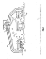
Figure 2 shows a more detailed view of a bearing arrangement shown inFigure 1 , including a carbon composite seal. -
Figure 3 shows a perspective view of an example carbon composite seal. -
Figure 4 schematically illustrates pores of a portion of the carbon composite seal. -
Figure 5 illustrates selected steps of an example cleaning process for preparing a carbon workpiece to be coated. -
Figure 1 illustrates selected portions of an examplegas turbine engine 10 including a fan 11, acompressor section 12, acombustor section 14, and aturbine section 16. Thegas turbine engine 10 operates in a generally known manner, feeding compressed air from acompressor section 12 to acombustor section 14. The compressed air is mixed with fuel and reacts to produce a stream ofhot gasses 18. Theturbine section 16 transforms the stream ofhot gasses 18 into mechanical energy to rotate adrive shaft 20, such as a turbine engine main shaft. Theshaft 20 is coupled with the fan 11, theturbine section 16, and thecompressor section 12 such that theturbine section 16 drives the fan 11 to produce thrust and drive thecompressor section 12. In this example, anexhaust nozzle 22 directs thehot gasses 18 out of thegas turbine engine 10. An annular,non-rotatable case 24 provides support for theshaft 20 on abearing arrangement 26, such as a No. 1 bearing. -
Figure 2 shows selected portions of theexample bearing arrangement 26 shown inFigure 1 . In this example, thebearing arrangement 26 includes abearing 36 located between thecase 24 and theshaft 20 that provides support for theshaft 20, which rotates about a central axis A. Aseal arrangement 38 provides fluid restriction between a low pressure and temperature region (L) within abearing chamber 40 and hot, high pressure region (H) outside of thebearing chamber 40. - In this example, a
seal arrangement 38 includes aseal 42 that is non-rotatably secured to thecase 24. Theseal 42 abuts against a piston ring 44 that rotates with theshaft 20. In this description, one of ordinary skill in the art will recognize alternative gas turbine engine arrangements that will benefit from the examples disclosed herein. Theseal 42 in this example includes a carboncomposite seal member 46 secured to ametal backing 48, as also depicted inFigure 3 . In other examples, or in other types of uses, the carboncomposite seal member 46 is used without themetal backing 48, or with another known type of backing. - In this example, the carbon
composite seal member 46 is made of graphitic carbon that is impregnated with a material that enhances the performance of the carboncomposite seal member 46. In one example the material includes phosphorous. In a further example, the phosphorous is a phosphorous salt. The phosphorous salt is located within pores within the graphitic carbon and functions to enhance durability of the carboncomposite seal member 46. - To further enhance the durability of the carbon
composite seal member 46, a coating 50 is deposited onto outer surfaces of the carboncomposite seal member 46. In one example, the coating 50 includes aluminum oxide or other suitable inorganic coating to enhance the durability of the carboncomposite seal member 46. For example, the coating 50 is deposited using a known thermal spray technique. - The carbon composite seal member 46 (i.e. a carbon work piece) is cleaned prior to depositing the coating 50 in order to promote adhesion between the graphitic carbon and the coating 50. The cleaning generally removes debris from the surfaces of the carbon
composite seal member 46 and infiltrates intopores 52 of the graphitic carbon to remove debris that may be within thepores 52, as shown schematically for example in a partial view of the carboncomposite seal member 46 inFigure 4 . - Referring to
Figure 5 , anexample cleaning process 58 is shown. In this example, the carboncomposite seal member 46 is first submersed in deionizedwater 59 at astep 60. In one example, the carboncomposite seal member 46 is soaked in the deionizedwater 59 for about 30 minutes to wash away phosphorous salt residing on the outer surfaces of the carboncomposite seal member 46. Removal of the phosphorous salt from the surfaces prevents the phosphorous salts from interfering with the adhesion between the coating 50 and the graphitic carbon. - At step 62, the carbon
composite seal member 46 is removed from the deionized water and brushed using abrush 63 to remove any air bubbles on the outer surfaces of the carboncomposite seal member 46. For example, the bubbles may inhibit the deionizedwater 59 from carrying debris out of thepores 52 and also prevent the deionizedwater 59 from infiltrating thepores 52 to remove the debris. - At
step 64, the carboncomposite seal member 46 is again soaked in deionizedwater 65 to further remove debris and to rinse existing debris from the surfaces. In one example, the carboncomposite seal member 46 is soaked in the deionizedwater 65 for about 30 minutes. Upon removal from the deionizedwater 65 atstep 66, the carboncomposite seal member 46 is dried in air, for example. In one example, ambient, dry air is blown over the surfaces of the carboncomposite seal member 46 to dry it. - After drying, the carbon
composite seal member 46 is submersed in anacetone cleaning agent 70. In this example, the carboncomposite seal member 46 is completely submersed in theacetone cleaning agent 70 such that the acetone can penetrate into thepores 52 of the graphitic carbon to remove debris that is lodged therein. In one example, the acetone is supplied by Union Carbide and has a viscosity at 25°C of about 0.306 x 10⁻³Pa·s. In some examples, the viscosity may vary by as much as 25% or even more, depending on the supplier and whether the acetone is mixed with other substances. - The viscosity of the acetone permits it to penetrate into the
pores 52 of the graphitic carbon to remove debris therefrom. Prior cleaning agents that are more viscous are not able to penetrate as far into thepores 52, and therefore are not able to achieve the desired level of cleaning that is possible using acetone. For example, the relatively low viscosity of the acetone permits it to penetrate a farther distance into thepores 52 compared to methanol or water. That is, the distance of penetration depends at least partially on the viscosity of the cleaning agent. Additionally, the acetone also provides the benefit of having a relatively lower amount of volatile organic compounds ("VOC") compared to other type of cleaning agents. - In one example, the acetone cleaning agent is equal or greater than 99% pure. Using acetone of this purity prevents the acetone from leaving residue on or within the carbon
composite seal member 46 from impurities in the acetone. - In another example, the
acetone cleaning agent 70 used atstep 68 is used over several cleaning cycles for different carboncomposite seal members 46 proceeding through thecleaning process 58. In this example, theacetone cleaning agent 70 is periodically inspected to ensure it is of suitable quality to properly clean the carboncomposite seal members 46. For example, a characteristic of theacetone cleaning agent 70 is measured periodically to determine whether or not it is contaminated. For example, the specific gravity of theacetone cleaning agent 70 is measured and theacetone cleaning agent 70 is discarded in favor of newacetone cleaning agent 70 if the specific gravity is above a threshold level. In one example, the threshold level is about 0.87 (e.g., wherein the initial specific gravity is about 0.79). - In the illustrated example, the carbon
composite seal member 46 is then removed from theacetone cleaning agent 70 and dried. For example, dry ambient air is blown over the surfaces of the carboncomposite seal member 46 to blow off any remainingacetone cleaning agent 70 or vaporize theacetone cleaning agent 70 from the surfaces thereof. - In this example, the carbon
composite seal member 46 is then transported to equipment for depositing the coating 50. In one example, if the carboncomposite seal member 46 cannot be coated within a certain time period, the carboncomposite seal member 46 is stored in an oven at an elevated temperature, such as 350°F +/-25°F (177°C +/- 14°C), until it can be coated. This prevents the carboncomposite seal member 46 from absorbing moisture that may inhibit adhesion between the coating 50 and the graphitic carbon. - Although a preferred embodiment of this invention has been disclosed, a worker of ordinary skill in this art would recognize that certain modifications would come within the scope of this invention. For that reason, the following claims should be studied to determine the true scope and content of this invention.
Claims (20)
- A method of cleaning a carbon work piece (46), comprising:(a) applying an acetone cleaning agent (70) to the carbon work piece (46) to remove debris from pores (52) of the carbon work piece (46).
- The method as recited in claim 1, wherein said step (a) includes completely submerging the carbon work piece (46) in a container holding the acetone cleaning agent (70).
- The method as recited in claim 1 or 2, wherein said step (a) includes reusing the acetone cleaning agent (70) to clean subsequent carbon work pieces (46) and establishing a threshold contamination level of the acetone cleaning agent (70) based upon a measured characteristic of the acetone cleaning agent (70).
- The method as recited in claim 1 or 2, wherein said step (a) includes reusing the acetone cleaning agent (70) to clean subsequent carbon work pieces (46) and establishing a threshold contamination level of the acetone cleaning agent (70) based upon a measured value of specific gravity of the acetone cleaning agent (70).
- The method as recited in any preceding claim, wherein said step (a) includes penetrating the acetone cleaning agent (70) a distance into the pores (52), wherein the distance depends at least partially on a viscosity of the acetone cleaning agent (70).
- The method as recited in any preceding claim, further comprising:(b) blowing ambient air over the carbon work piece (46) to remove the acetone cleaning agent (70) therefrom.
- The method as recited in any preceding claim, further comprising:(b) soaking the carbon work piece (46) in deionized water (59) before said step (a).
- The method as recited in claim 7, further comprising:(c) removing the carbon work piece (46) from the deionized water (59) and brushing the carbon work piece (46) to remove air bubbles therefrom before said step (a).
- The method as recited in claim 8, further comprising:(d) blowing ambient air over the carbon work piece (46) to remove the deionized water (59) therefrom.
- The method as recited in any preceding claim, further comprising:(b) depositing a coating (50) on the carbon work piece (46).
- The method as recited in claim 10, wherein said step (b) includes thermally depositing the coating (50) on the carbon work piece (46), wherein the coating (50) comprises aluminum oxide.
- The method recited in any preceding claim, wherein the carbon work piece (46) comprises graphite.
- The method recited in any preceding claim, wherein the carbon work piece (46) comprises graphite impregnated with a material having phosphorous.
- The method recited in any preceding claim, wherein the acetone cleaning agent (70) is at least 99% pure before said step (a).
- The method recited in any preceding claim, wherein the acetone cleaning agent (70) comprises a viscosity at 25°C of about 0.306x10⁻³ Pa.s.
- A method of cleaning a carbon work piece (46), comprising:(a) soaking the carbon work piece (46) in deionized water (59);(b) removing the carbon work piece (46) from the deionized water (59) and brushing the carbon work piece (46) to remove air bubbles therefrom;(c) applying an acetone cleaning agent (70) to the carbon work piece (46) to remove debris therefrom; and(d) depositing a coating on the carbon work piece (46).
- The method as recited in claim 16, wherein said step (b) includes completely submerging the carbon work piece (46) in a container holding the acetone cleaning agent (70).
- The method as recited in claim 16 or 17, further comprising:(e) blowing ambient air over the carbon work piece (46) to remove the acetone cleaning agent (70) from the carbon work piece (46) after said step (c).
- A method of cleaning a carbon work piece (46), comprising:(a) applying a cleaning agent having a solvent with a viscosity at 25°C that is about 0.306x10⁻³ Pa·s +/- 25% to the carbon work piece (46) to remove debris from pores (52) of the carbon work piece (46).
- A carbon seal (46) for use in a gas turbine engine, wherein the carbon seal (46) is produced from the carbon work piece (46) using the method recited in any preceding claim.
Applications Claiming Priority (1)
| Application Number | Priority Date | Filing Date | Title |
|---|---|---|---|
| US11/590,944 US8840960B2 (en) | 2006-11-01 | 2006-11-01 | Method of cleaning carbon composite prior to application of thermal coating |
Publications (3)
| Publication Number | Publication Date |
|---|---|
| EP1953349A2 true EP1953349A2 (en) | 2008-08-06 |
| EP1953349A3 EP1953349A3 (en) | 2008-11-26 |
| EP1953349B1 EP1953349B1 (en) | 2010-10-27 |
Family
ID=39328670
Family Applications (1)
| Application Number | Title | Priority Date | Filing Date |
|---|---|---|---|
| EP07254306A Not-in-force EP1953349B1 (en) | 2006-11-01 | 2007-10-30 | Method of cleaning carbon composite prior to application of thermal coating |
Country Status (3)
| Country | Link |
|---|---|
| US (1) | US8840960B2 (en) |
| EP (1) | EP1953349B1 (en) |
| DE (1) | DE602007010087D1 (en) |
Family Cites Families (15)
| Publication number | Priority date | Publication date | Assignee | Title |
|---|---|---|---|---|
| US2233442A (en) * | 1938-05-31 | 1941-03-04 | Dow Chemical Co | Polymeric vinylidene chloride article |
| US3868485A (en) * | 1972-09-07 | 1975-02-25 | Hunt Philip A | Density sensing probe switch with adjustable float |
| GB2131895B (en) * | 1982-12-14 | 1986-04-23 | Rolls Royce | Improvements in or relating to seals |
| US5317901A (en) * | 1985-12-10 | 1994-06-07 | United Technologies Corporation | Nondestructive test for coated carbon-carbon composite articles |
| FR2594149B1 (en) * | 1986-02-13 | 1988-11-25 | Centre Tech Teinture Nettoyage | METHOD FOR CONTROLLING SOLVENT SOILING ON DRY CLEANING INSTALLATIONS AND MONITORING APPARATUS COMPRISING NEW TYPES OF SENSORS FOR IMPLEMENTING IT. |
| DE3611938C1 (en) * | 1986-04-09 | 1987-10-15 | Kernforschungsanlage Juelich | Cathode-membrane unit and process for its manufacture |
| US5071517A (en) * | 1989-11-21 | 1991-12-10 | Solution Technology Systems | Method for directly electroplating a dielectric substrate and plated substrate so produced |
| US5443651A (en) * | 1990-02-06 | 1995-08-22 | Monsanto Company | Process for metal cleaning |
| US5320879A (en) * | 1992-07-20 | 1994-06-14 | Hughes Missile Systems Co. | Method of forming coatings by plasma spraying magnetic-cerment dielectric composite particles |
| JPH07147265A (en) * | 1993-11-25 | 1995-06-06 | Sony Corp | Cleaning method and cleaning device |
| US5538641A (en) * | 1994-12-29 | 1996-07-23 | Global Environmental Solutions, Inc. | Process for recycling laden fluids |
| US5997979A (en) * | 1996-06-27 | 1999-12-07 | Oiles Corporation | Spherical annular seal member and method of manufacturing the same |
| US5710373A (en) * | 1997-02-18 | 1998-01-20 | Safety-Kleen Corporation | Visual comparator with test chart and method for evaluating contamination of washing fluids |
| US6682604B1 (en) | 2000-05-22 | 2004-01-27 | Rochester Institute Of Technology | Restoration of contaminated polymer articles |
| BRPI0520574A2 (en) | 2005-09-30 | 2009-05-19 | Airbus Espana Sl | surface treatment method of composite material structures with atmospheric plasma beams |
-
2006
- 2006-11-01 US US11/590,944 patent/US8840960B2/en not_active Expired - Fee Related
-
2007
- 2007-10-30 DE DE602007010087T patent/DE602007010087D1/en active Active
- 2007-10-30 EP EP07254306A patent/EP1953349B1/en not_active Not-in-force
Non-Patent Citations (1)
| Title |
|---|
| None |
Also Published As
| Publication number | Publication date |
|---|---|
| US20080099044A1 (en) | 2008-05-01 |
| US8840960B2 (en) | 2014-09-23 |
| EP1953349A3 (en) | 2008-11-26 |
| EP1953349B1 (en) | 2010-10-27 |
| DE602007010087D1 (en) | 2010-12-09 |
Similar Documents
| Publication | Publication Date | Title |
|---|---|---|
| US6827969B1 (en) | Field repairable high temperature smooth wear coating | |
| US7588797B2 (en) | Field repairable high temperature smooth wear coating | |
| JP4651966B2 (en) | Field methods and compositions for repairing thermal barrier coatings | |
| CA2330218C (en) | Method of removing a thermal barrier coating | |
| EP1739204B1 (en) | Field repairable high temperature smooth wear coating | |
| US6454870B1 (en) | Chemical removal of a chromium oxide coating from an article | |
| CN1205357C (en) | Method for forming protective film, material for forming protective film, and sheet for forming abrasive protective film | |
| CN102498346B (en) | For the manufacture of the method for the pull-out guide of band coating | |
| JP2008111425A (en) | Friction coating for gas turbine engine compressor | |
| JP2008069448A (en) | Method for processing titanium alloy component | |
| CA2581985A1 (en) | Method of forming stabilized plasma-sprayed thermal barrier coatings | |
| JP2011088140A (en) | Method for cleaning substrate | |
| CN111250368A (en) | Preparation process of polyphenyl ester sealing coating for aero-engine case parts | |
| RU2062303C1 (en) | Method of applying coating on blades of heat turbomachine | |
| US12076885B2 (en) | Repair process using networked ceramic nanofibers | |
| EP1795629A3 (en) | Oxide cleaning and coating of metallic components | |
| US11260421B2 (en) | Method to strip and recoat erosion coatings applied to fan blades and structural guide vanes | |
| US8840960B2 (en) | Method of cleaning carbon composite prior to application of thermal coating | |
| JP2012527537A (en) | Method for improving the corrosion and oxidation resistance of the lower platform region of a gas turbine blade | |
| JP2012527536A (en) | Corrosion-resistant article | |
| US10662517B2 (en) | Aluminum fan blade tip prepared for thermal spray deposition of abrasive by laser ablation | |
| US7097783B2 (en) | Method for inspecting a titanium-based component | |
| EP2104591B1 (en) | Process for surface preparation of parts to be coated | |
| EP1548156B1 (en) | Process for removing adherent oxide particles from an aluminized surface | |
| CN100443264C (en) | Fast continuous process of eliminting coating in vacuum coating tray |
Legal Events
| Date | Code | Title | Description |
|---|---|---|---|
| PUAI | Public reference made under article 153(3) epc to a published international application that has entered the european phase |
Free format text: ORIGINAL CODE: 0009012 |
|
| AK | Designated contracting states |
Kind code of ref document: A2 Designated state(s): AT BE BG CH CY CZ DE DK EE ES FI FR GB GR HU IE IS IT LI LT LU LV MC MT NL PL PT RO SE SI SK TR |
|
| AX | Request for extension of the european patent |
Extension state: AL BA HR MK RS |
|
| PUAL | Search report despatched |
Free format text: ORIGINAL CODE: 0009013 |
|
| RIC1 | Information provided on ipc code assigned before grant |
Ipc: F01D 25/00 20060101AFI20080627BHEP Ipc: B08B 3/08 20060101ALI20081010BHEP Ipc: B08B 3/04 20060101ALI20081010BHEP |
|
| AK | Designated contracting states |
Kind code of ref document: A3 Designated state(s): AT BE BG CH CY CZ DE DK EE ES FI FR GB GR HU IE IS IT LI LT LU LV MC MT NL PL PT RO SE SI SK TR |
|
| AX | Request for extension of the european patent |
Extension state: AL BA HR MK RS |
|
| 17P | Request for examination filed |
Effective date: 20090107 |
|
| 17Q | First examination report despatched |
Effective date: 20090217 |
|
| AKX | Designation fees paid |
Designated state(s): DE GB |
|
| GRAP | Despatch of communication of intention to grant a patent |
Free format text: ORIGINAL CODE: EPIDOSNIGR1 |
|
| GRAS | Grant fee paid |
Free format text: ORIGINAL CODE: EPIDOSNIGR3 |
|
| GRAA | (expected) grant |
Free format text: ORIGINAL CODE: 0009210 |
|
| AK | Designated contracting states |
Kind code of ref document: B1 Designated state(s): DE GB |
|
| REG | Reference to a national code |
Ref country code: GB Ref legal event code: FG4D |
|
| REF | Corresponds to: |
Ref document number: 602007010087 Country of ref document: DE Date of ref document: 20101209 Kind code of ref document: P |
|
| PLBE | No opposition filed within time limit |
Free format text: ORIGINAL CODE: 0009261 |
|
| STAA | Information on the status of an ep patent application or granted ep patent |
Free format text: STATUS: NO OPPOSITION FILED WITHIN TIME LIMIT |
|
| 26N | No opposition filed |
Effective date: 20110728 |
|
| REG | Reference to a national code |
Ref country code: DE Ref legal event code: R097 Ref document number: 602007010087 Country of ref document: DE Effective date: 20110728 |
|
| PGFP | Annual fee paid to national office [announced via postgrant information from national office to epo] |
Ref country code: DE Payment date: 20121024 Year of fee payment: 6 |
|
| PGFP | Annual fee paid to national office [announced via postgrant information from national office to epo] |
Ref country code: GB Payment date: 20121024 Year of fee payment: 6 |
|
| GBPC | Gb: european patent ceased through non-payment of renewal fee |
Effective date: 20131030 |
|
| PG25 | Lapsed in a contracting state [announced via postgrant information from national office to epo] |
Ref country code: GB Free format text: LAPSE BECAUSE OF NON-PAYMENT OF DUE FEES Effective date: 20131030 |
|
| REG | Reference to a national code |
Ref country code: DE Ref legal event code: R119 Ref document number: 602007010087 Country of ref document: DE Effective date: 20140501 |
|
| PG25 | Lapsed in a contracting state [announced via postgrant information from national office to epo] |
Ref country code: DE Free format text: LAPSE BECAUSE OF NON-PAYMENT OF DUE FEES Effective date: 20140501 |