EP1953030A1 - Controller for inverter - Google Patents
Controller for inverter Download PDFInfo
- Publication number
- EP1953030A1 EP1953030A1 EP08001127A EP08001127A EP1953030A1 EP 1953030 A1 EP1953030 A1 EP 1953030A1 EP 08001127 A EP08001127 A EP 08001127A EP 08001127 A EP08001127 A EP 08001127A EP 1953030 A1 EP1953030 A1 EP 1953030A1
- Authority
- EP
- European Patent Office
- Prior art keywords
- processing unit
- inverter
- motor control
- control processing
- controller
- Prior art date
- Legal status (The legal status is an assumption and is not a legal conclusion. Google has not performed a legal analysis and makes no representation as to the accuracy of the status listed.)
- Granted
Links
Images



Classifications
-
- B—PERFORMING OPERATIONS; TRANSPORTING
- B60—VEHICLES IN GENERAL
- B60L—PROPULSION OF ELECTRICALLY-PROPELLED VEHICLES; SUPPLYING ELECTRIC POWER FOR AUXILIARY EQUIPMENT OF ELECTRICALLY-PROPELLED VEHICLES; ELECTRODYNAMIC BRAKE SYSTEMS FOR VEHICLES IN GENERAL; MAGNETIC SUSPENSION OR LEVITATION FOR VEHICLES; MONITORING OPERATING VARIABLES OF ELECTRICALLY-PROPELLED VEHICLES; ELECTRIC SAFETY DEVICES FOR ELECTRICALLY-PROPELLED VEHICLES
- B60L3/00—Electric devices on electrically-propelled vehicles for safety purposes; Monitoring operating variables, e.g. speed, deceleration or energy consumption
- B60L3/0023—Detecting, eliminating, remedying or compensating for drive train abnormalities, e.g. failures within the drive train
- B60L3/003—Detecting, eliminating, remedying or compensating for drive train abnormalities, e.g. failures within the drive train relating to inverters
-
- B—PERFORMING OPERATIONS; TRANSPORTING
- B60—VEHICLES IN GENERAL
- B60L—PROPULSION OF ELECTRICALLY-PROPELLED VEHICLES; SUPPLYING ELECTRIC POWER FOR AUXILIARY EQUIPMENT OF ELECTRICALLY-PROPELLED VEHICLES; ELECTRODYNAMIC BRAKE SYSTEMS FOR VEHICLES IN GENERAL; MAGNETIC SUSPENSION OR LEVITATION FOR VEHICLES; MONITORING OPERATING VARIABLES OF ELECTRICALLY-PROPELLED VEHICLES; ELECTRIC SAFETY DEVICES FOR ELECTRICALLY-PROPELLED VEHICLES
- B60L3/00—Electric devices on electrically-propelled vehicles for safety purposes; Monitoring operating variables, e.g. speed, deceleration or energy consumption
- B60L3/0023—Detecting, eliminating, remedying or compensating for drive train abnormalities, e.g. failures within the drive train
- B60L3/0084—Detecting, eliminating, remedying or compensating for drive train abnormalities, e.g. failures within the drive train relating to control modules
-
- B—PERFORMING OPERATIONS; TRANSPORTING
- B60—VEHICLES IN GENERAL
- B60L—PROPULSION OF ELECTRICALLY-PROPELLED VEHICLES; SUPPLYING ELECTRIC POWER FOR AUXILIARY EQUIPMENT OF ELECTRICALLY-PROPELLED VEHICLES; ELECTRODYNAMIC BRAKE SYSTEMS FOR VEHICLES IN GENERAL; MAGNETIC SUSPENSION OR LEVITATION FOR VEHICLES; MONITORING OPERATING VARIABLES OF ELECTRICALLY-PROPELLED VEHICLES; ELECTRIC SAFETY DEVICES FOR ELECTRICALLY-PROPELLED VEHICLES
- B60L3/00—Electric devices on electrically-propelled vehicles for safety purposes; Monitoring operating variables, e.g. speed, deceleration or energy consumption
- B60L3/0092—Electric devices on electrically-propelled vehicles for safety purposes; Monitoring operating variables, e.g. speed, deceleration or energy consumption with use of redundant elements for safety purposes
-
- B—PERFORMING OPERATIONS; TRANSPORTING
- B60—VEHICLES IN GENERAL
- B60L—PROPULSION OF ELECTRICALLY-PROPELLED VEHICLES; SUPPLYING ELECTRIC POWER FOR AUXILIARY EQUIPMENT OF ELECTRICALLY-PROPELLED VEHICLES; ELECTRODYNAMIC BRAKE SYSTEMS FOR VEHICLES IN GENERAL; MAGNETIC SUSPENSION OR LEVITATION FOR VEHICLES; MONITORING OPERATING VARIABLES OF ELECTRICALLY-PROPELLED VEHICLES; ELECTRIC SAFETY DEVICES FOR ELECTRICALLY-PROPELLED VEHICLES
- B60L3/00—Electric devices on electrically-propelled vehicles for safety purposes; Monitoring operating variables, e.g. speed, deceleration or energy consumption
- B60L3/04—Cutting off the power supply under fault conditions
-
- B—PERFORMING OPERATIONS; TRANSPORTING
- B60—VEHICLES IN GENERAL
- B60L—PROPULSION OF ELECTRICALLY-PROPELLED VEHICLES; SUPPLYING ELECTRIC POWER FOR AUXILIARY EQUIPMENT OF ELECTRICALLY-PROPELLED VEHICLES; ELECTRODYNAMIC BRAKE SYSTEMS FOR VEHICLES IN GENERAL; MAGNETIC SUSPENSION OR LEVITATION FOR VEHICLES; MONITORING OPERATING VARIABLES OF ELECTRICALLY-PROPELLED VEHICLES; ELECTRIC SAFETY DEVICES FOR ELECTRICALLY-PROPELLED VEHICLES
- B60L50/00—Electric propulsion with power supplied within the vehicle
- B60L50/10—Electric propulsion with power supplied within the vehicle using propulsion power supplied by engine-driven generators, e.g. generators driven by combustion engines
- B60L50/16—Electric propulsion with power supplied within the vehicle using propulsion power supplied by engine-driven generators, e.g. generators driven by combustion engines with provision for separate direct mechanical propulsion
-
- B—PERFORMING OPERATIONS; TRANSPORTING
- B60—VEHICLES IN GENERAL
- B60L—PROPULSION OF ELECTRICALLY-PROPELLED VEHICLES; SUPPLYING ELECTRIC POWER FOR AUXILIARY EQUIPMENT OF ELECTRICALLY-PROPELLED VEHICLES; ELECTRODYNAMIC BRAKE SYSTEMS FOR VEHICLES IN GENERAL; MAGNETIC SUSPENSION OR LEVITATION FOR VEHICLES; MONITORING OPERATING VARIABLES OF ELECTRICALLY-PROPELLED VEHICLES; ELECTRIC SAFETY DEVICES FOR ELECTRICALLY-PROPELLED VEHICLES
- B60L50/00—Electric propulsion with power supplied within the vehicle
- B60L50/50—Electric propulsion with power supplied within the vehicle using propulsion power supplied by batteries or fuel cells
- B60L50/60—Electric propulsion with power supplied within the vehicle using propulsion power supplied by batteries or fuel cells using power supplied by batteries
- B60L50/61—Electric propulsion with power supplied within the vehicle using propulsion power supplied by batteries or fuel cells using power supplied by batteries by batteries charged by engine-driven generators, e.g. series hybrid electric vehicles
-
- H—ELECTRICITY
- H02—GENERATION; CONVERSION OR DISTRIBUTION OF ELECTRIC POWER
- H02P—CONTROL OR REGULATION OF ELECTRIC MOTORS, ELECTRIC GENERATORS OR DYNAMO-ELECTRIC CONVERTERS; CONTROLLING TRANSFORMERS, REACTORS OR CHOKE COILS
- H02P29/00—Arrangements for regulating or controlling electric motors, appropriate for both AC and DC motors
- H02P29/02—Providing protection against overload without automatic interruption of supply
- H02P29/024—Detecting a fault condition, e.g. short circuit, locked rotor, open circuit or loss of load
- H02P29/0241—Detecting a fault condition, e.g. short circuit, locked rotor, open circuit or loss of load the fault being an overvoltage
-
- Y—GENERAL TAGGING OF NEW TECHNOLOGICAL DEVELOPMENTS; GENERAL TAGGING OF CROSS-SECTIONAL TECHNOLOGIES SPANNING OVER SEVERAL SECTIONS OF THE IPC; TECHNICAL SUBJECTS COVERED BY FORMER USPC CROSS-REFERENCE ART COLLECTIONS [XRACs] AND DIGESTS
- Y02—TECHNOLOGIES OR APPLICATIONS FOR MITIGATION OR ADAPTATION AGAINST CLIMATE CHANGE
- Y02T—CLIMATE CHANGE MITIGATION TECHNOLOGIES RELATED TO TRANSPORTATION
- Y02T10/00—Road transport of goods or passengers
- Y02T10/60—Other road transportation technologies with climate change mitigation effect
- Y02T10/62—Hybrid vehicles
-
- Y—GENERAL TAGGING OF NEW TECHNOLOGICAL DEVELOPMENTS; GENERAL TAGGING OF CROSS-SECTIONAL TECHNOLOGIES SPANNING OVER SEVERAL SECTIONS OF THE IPC; TECHNICAL SUBJECTS COVERED BY FORMER USPC CROSS-REFERENCE ART COLLECTIONS [XRACs] AND DIGESTS
- Y02—TECHNOLOGIES OR APPLICATIONS FOR MITIGATION OR ADAPTATION AGAINST CLIMATE CHANGE
- Y02T—CLIMATE CHANGE MITIGATION TECHNOLOGIES RELATED TO TRANSPORTATION
- Y02T10/00—Road transport of goods or passengers
- Y02T10/60—Other road transportation technologies with climate change mitigation effect
- Y02T10/64—Electric machine technologies in electromobility
-
- Y—GENERAL TAGGING OF NEW TECHNOLOGICAL DEVELOPMENTS; GENERAL TAGGING OF CROSS-SECTIONAL TECHNOLOGIES SPANNING OVER SEVERAL SECTIONS OF THE IPC; TECHNICAL SUBJECTS COVERED BY FORMER USPC CROSS-REFERENCE ART COLLECTIONS [XRACs] AND DIGESTS
- Y02—TECHNOLOGIES OR APPLICATIONS FOR MITIGATION OR ADAPTATION AGAINST CLIMATE CHANGE
- Y02T—CLIMATE CHANGE MITIGATION TECHNOLOGIES RELATED TO TRANSPORTATION
- Y02T10/00—Road transport of goods or passengers
- Y02T10/60—Other road transportation technologies with climate change mitigation effect
- Y02T10/70—Energy storage systems for electromobility, e.g. batteries
-
- Y—GENERAL TAGGING OF NEW TECHNOLOGICAL DEVELOPMENTS; GENERAL TAGGING OF CROSS-SECTIONAL TECHNOLOGIES SPANNING OVER SEVERAL SECTIONS OF THE IPC; TECHNICAL SUBJECTS COVERED BY FORMER USPC CROSS-REFERENCE ART COLLECTIONS [XRACs] AND DIGESTS
- Y02—TECHNOLOGIES OR APPLICATIONS FOR MITIGATION OR ADAPTATION AGAINST CLIMATE CHANGE
- Y02T—CLIMATE CHANGE MITIGATION TECHNOLOGIES RELATED TO TRANSPORTATION
- Y02T10/00—Road transport of goods or passengers
- Y02T10/60—Other road transportation technologies with climate change mitigation effect
- Y02T10/7072—Electromobility specific charging systems or methods for batteries, ultracapacitors, supercapacitors or double-layer capacitors
-
- Y—GENERAL TAGGING OF NEW TECHNOLOGICAL DEVELOPMENTS; GENERAL TAGGING OF CROSS-SECTIONAL TECHNOLOGIES SPANNING OVER SEVERAL SECTIONS OF THE IPC; TECHNICAL SUBJECTS COVERED BY FORMER USPC CROSS-REFERENCE ART COLLECTIONS [XRACs] AND DIGESTS
- Y02—TECHNOLOGIES OR APPLICATIONS FOR MITIGATION OR ADAPTATION AGAINST CLIMATE CHANGE
- Y02T—CLIMATE CHANGE MITIGATION TECHNOLOGIES RELATED TO TRANSPORTATION
- Y02T90/00—Enabling technologies or technologies with a potential or indirect contribution to GHG emissions mitigation
- Y02T90/10—Technologies relating to charging of electric vehicles
- Y02T90/16—Information or communication technologies improving the operation of electric vehicles
Definitions
- the present invention relates to controllers for inverter and more particularly to a controller for inverter provided with fail-safe means at the time of a failure detected.
- an inverter controller For a controller for inverter (hereinafter this may be called an inverter controller also), it is necessary to improve the reliability of a system. Particularly, in the case of a cooperation control system including a plurality of processing units, a fail-safe function at the time of a failure detected in a processing unit, for example, is important.
- JP Published Patent Application No. H 10-289001 A (1998 ) discloses a control system as a redundant system including a main controller and a sub-controller therein.
- the provision of the sub-controller improves the reliability of the system when something abnormal occurs in the main controller.
- a typical controller for inverter of the present invention may include: an energy management processing unit that controls energy of a vehicle; a first motor control processing unit that controls a power generation amount or an assist amount of a first motor; a second motor control processing unit that controls a power generation amount or an assist amount of a second motor; a power supply unit that generates power supplied to the energy management processing unit, the first motor control processing unit and the second motor control processing unit; a first inverter that is controlled by the first motor control processing unit; a second inverter that is controlled by the second motor control processing unit; and/or a communication line that connects the energy management processing unit, the first motor control processing unit and the second motor control processing unit.
- the first inverter and the second inverter are controlled in a cooperative or an independent manner.
- Another typical controller for inverter of the present invention may include: a first inverter that drives a first motor; a second inverter that drives a second motor; a first processing unit (MCP1) that outputs a first signal (PWM signal) to control the first inverter; a second processing unit (MCP2) that outputs a second signal (PWM signal) to control the second inverter; and/or a connection line that connects the first processing unit and the second processing unit. If an abnormality is detected in the first processing unit, control of the first inverter based on the first signal is stopped, and control of the second inverter based on the second signal is continued.
- a high-reliability controller for inverter can be provided with a simple configuration.
- the above features may be combined in any way, partly or as a whole.
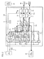
- Fig. 1 shows the configuration of a system of the present invention.
- Reference numeral 1 denotes a 12V-battery, which supplies a constant voltage around 12V to an inverter controller 100.
- Reference numeral 2 denotes an ignition switch. When a user turns the ignition switch 2 ON, electricity is supplied from the 12V-battery 1 to the inverter controller 100, so that the inverter controller 100 starts to operate.
- Reference numeral 3 denotes a detector for the ignition switch 2, which makes a judgment of ON/OFF of the ignition switch 2.
- the detector 3 When the ignition switch 2 turns ON, the detector 3 outputs HIGH as a detection signal 3a to an OR gate 4.
- a switch 6 of a gate power supply 5, a switch 9 of a regulator 8 in an intra-inverter power supply 7, and a switch 13 in a regulator 12 of a first logic 10 and a second logic 11 are turned ON so as to activate the gate power supply 5, the regulator 8 and the regulator 12, whereby the inverter controller 100 operates.
- the OR gate 4 is configured so as to receive, as input, the detection signal 3a output from the detector 3 for the ignition switch 2 and power-hold signals 14b, 15b and 16b which are output from a CPU 14 (HCP: Hybrid Control Processor), a CPU 15 (MCP1: Motor Control Processor 1) and a CPU 16 (MCP2: Motor Control Processor 2), respectively.
- HCP Hybrid Control Processor
- MCP1 Motor Control Processor 1
- MCP2 Motor Control Processor 2
- These four signals of the detection signal 3a and the power-hold signals 14b, 15b and 16b enable the control of the power supply.
- the CPU 14 is an energy management processing unit for performing hybrid integration control
- the CPU 15 is a first motor control processing unit for controlling a first motor 26
- the CPU 16 is a second motor control processing unit for controlling a second motor 27.
- the detection signal 3a from the detector 3 for the ignition switch 2 is input also to the CPU 14, the CPU 15 and the CPU 16. With this configuration, the CPUs 14, 15 and 16 can detect the state of the ignition switch 2. When the detection signal 3a from the detector 3 for the ignition switch 2 is HIGH, the CPUs 14, 15 and 16 output the power-hold signals 14b, 15b and 16b, respectively, to the OR gate 4.
- a voltage 8a generated at the regulator 8 is input to the CPUs 14, 15 and 16, which functions as a power supply of the respective CPUs.
- the CPUs 14, 15 and 16 are connected via a communication line 17.
- the communication line 17 allows the CPUs to communicate with each other.
- the communication line 17 is further connected with an external controller of the inverter controller 100, e.g., with an engine controller 28, so that the engine controller 28 can communicate with the CPUs 14,15 and 16 mutually.
- the inverter controller 100 does not internally include a host CPU for communication with the external controller. Therefore, the CPUs 14, 15 and 16 in the inverter controller 100 and the engine controller 28 can communicate with each other.
- the CPUs 14, 15 and 16 and the engine controller 28 monitor each other via the communication line 17, thus enabling the detection of normality/abnormality of their functions individually.
- Reference numerals 18 to 20 denote watchdog timers (WDTs).
- the WDTs 18, 19 and 20 monitor the CPUs 14, 15 and 16, respectively. That is, the CPUs 14, 15 and 16 are configured so as to monitor each other via the communication line 17 to detect the normality/abnormality, while being judged by the WDTs 18 to 20 about their normality/abnormality.
- a voltage 12a generated at the regulator 12 is supplied to the first logic 10 and the second logic 11. Since there is a need to consider the fail-safe when an abnormality occurs, between the regulator 12 and the first logic 10 is provided a switch 21 for the first logic 10, and between the regulator 12 and the second logic 11 is provided a switch 22 for the second logic 11.
- the switch 21 is for shutting off the power supply for the first logic 10.
- an instruction value 15a shuts off the power supply of the first logic 10 so as to completely stop an instruction to a first inverter 23 at a latter stage.
- the switch 22 is for shutting off the power supply for the second logic 11.
- an instruction value 16a shuts off the power supply of the second logic 11 so as to completely stop an instruction to a second inverter 24 at a latter stage.
- Reference numeral 25 denotes a high-voltage battery. For instance, this may be a high-voltage power supply of 288V, and functions as a main power supply of the first inverter 23 and the second inverter 24.
- An instruction value 10a from the first logic 10 is output for driving and controlling a power module (not illustrated) in the first inverter 23.
- a gate driving signal which is for controlling a switching element such as an IGBT or a MOSFET included in the power module, is based on the power supplied from the gate power supply 5. Note here that across the power supply of the power module, i.e., between an anode and a cathode of a switching element making up upper arm/lower arm is applied a high-voltage power supplied from the high-voltage battery 25. This configuration allows the first motor 26 to be driven by the high-voltage battery 25 as a power supply, thus enabling the driving at a large torque.
- An instruction value 11a from the second logic 11 is output for driving and controlling a power module (not illustrated) in the second inverter 24.
- a gate driving signal which is for controlling a switching element such as an IGBT or a MOSFET included in the power module, is based on the power supplied from the gate power supply 5. Note here that across the power supply of the power module, i.e., between an anode and a cathode of a switching element making up upper arm/lower arm is applied a high-voltage power supplied from the high-voltage battery 25. This configuration allows the second motor 27 also to be driven by the high-voltage battery 25 as a power supply, thus enabling the driving at a large torque.
- the first logic 10 is controlled by a PWM signal 15b output from the CPU 15, and the second logic 11 is controlled by a PWM signal 16b output from the CPU 16.
- a hybrid-system vehicle to which the inverter controller 100 of the present embodiment is applied is subjected to the integration control by the CPU 14.
- a torque amount required for the engine is transmitted to the engine controller 28 via the communication line 17.
- the engine, the first motor 26 and the second motor 27 are subjected to the integration control, thus enabling the optimal control of the vehicle as a whole.
- the detector 3 for the ignition switch 2 detects that the ignition switch 2 has turned OFF. At this time, the detection signal 3a output from the detector 3 for the ignition switch 2 turns LOW, and such a detection signal 3a is input to the CPUs 14,15 and 16.
- the CPUs 14,15 and 16 start a key-off sequence.
- the CPU 14 turns 14b LOW
- the CPU 15 turns 15b LOW
- the CPU 16 turns 16b LOW.
- Such an operation causes the electrical shut-off between the 12V-battery 1 and the inverter controller 100. Therefore, a dark current can be reduced, so that the consumption current of the 12V-battery 1 can be reduced.
- Fig. 2 shows the configuration of a system according to Embodiment 2 of the present invention.
- each of CPUs 14 to 16 of the present embodiment is provided with an independent power supply.
- Reference numeral 31 denotes a power supply for the CPU 14.
- a switch 34 for a regulator 35 included in the power supply 31 turns ON, so that power 35a is applied to the CPU 14.
- Reference numeral 32 denotes a power supply for the CPU 15.
- a switch 36 for a regulator 37 included in the power supply 32 turns ON, so that power 36a is applied to the CPU 15.
- Reference numeral 33 denotes a power supply for the CPU 16.
- a switch 38 for a regulator 39 included in the power supply 33 turns ON, so that power 39a is applied to the CPU 16.
- Embodiment 1 is different from Embodiment 1 in that the power supplies are independently provided to the CPUs 14, 15 and 16, the basic operation is similar to that of Embodiment 1.
- FIG. 1 Another difference from Fig. 1 is to add a switch 40 and a regulator 41.
- the switch 40 of the regulator 41 also is controlled by the OR gate 4 in a similar manner to Embodiment 1.
- Output 41 a of the regulator 41 is a constant voltage that is commonly input to the CPUs 14,15 and 16.
- the CPU 14 sets the output 41 a of the regulator 41 as a reference voltage of a first AD converter.
- This first AD converter AD-converts output 35a of the regulator 35.
- the CPU 15 sets the output 41 a of the regulator 41 as a reference voltage of an AD converter.
- This AD converter AD-converts output 37a of the regulator 37.
- the CPU 16 sets the output 41 a of the regulator 41 as a reference voltage of an AD converter.
- This AD converter AD-converts output 39a of the regulator 39.
- the CPU 14 sets the output 35a of the regulator 35 as a reference voltage of a second AD converter.
- This second AD converter AD-converts the output 41 a of the regulator 41.
- the CPU 15 sets the output 37a of the regulator 37 as a reference voltage of an AD converter.
- This AD converter AD-converts the output 41a of the regulator 41.
- the CPU 16 sets the output 39a of the regulator 39 as a reference voltage of an AD converter.
- This AD converter AD-converts the output 41 a of the regulator 41.
- the above-stated two AD function diagnoses allow the CPUs 14, 15 and 16 to diagnose the respective regulator output voltages. Further, as an additional function, the respective AD converter functions of the CPUs 14, 15 and 16 can be diagnosed, so that a high-reliability system can be provided.
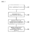
- Fig. 3 shows the fail-safe function when the CPU 14 is in an abnormal state in Embodiment 1 or Embodiment 2.
- the WDT 18, the CPU 15, the CPU 16 or the engine controller 28 detects that the function of the CPU 14 is in an abnormal state.
- the CPU 15 and the CPU 16 continuously control the first motor 26 and the second motor 27, respectively. However, since the integration control by the CPU 14 is disabled, the cooperation control is performed between the CPU 15 and the CPU 16.
- the first motor 26 may function as a generator and the second motor 27 may function as a vehicle-assist motor, where the amount of power generated in the vehicle and the amount of the vehicle assist are made to cooperate, so as to allow the optimum control of the remaining amount in the high-voltage battery 25.
- the CPU 16 controlling the vehicle-assist motor transmits the torque instruction value that indicates the torque amount required for the engine to the engine controller 28 via the communication line 17.
- the engine controller 28 controls the engine based on the torque instruction value.
- Fig. 4 shows the fail-safe function when the CPU 15 is in an abnormal state in Embodiment 1 or Embodiment 2.
- the WDT 19, the CPU 14, the CPU 16 or the engine controller 28 detects that the function of the CPU 15 is in an abnormal state.
- the switch 21 is turned OFF so as to disconnect the first logic 10 and the first inverter 23, thus completely stopping the first motor 26. This function can prevent the abnormal operation of the first motor 26.
- the CPU 14 changes the instruction value for the CPU 16 so that the second motor 27 functions as a vehicle-assist motor or a brake regenerative motor.
- the engine controller 28 controls the engine optimally based on the torque instruction value from the CPU 14.
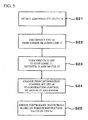
- Fig. 5 shows the fail-safe function when the CPU 16 is in an abnormal state in Embodiment 1 or Embodiment 2.
- the WDT 20, the CPU 14, the CPU 15 or the engine controller 28 detects that the function of the CPU 16 is in an abnormal state.
- the switch 22 is turned OFF so as to disconnect the second logic 11 and the second inverter 24, thus completely stopping the second motor 27. This function can prevent the abnormal operation of the second motor 27.
- the CPU 14 changes the instruction value for the CPU 15 so that the first motor 26 functions as a vehicle-assist motor or a brake regenerative motor.
- the engine controller 28 controls the engine optimally based on the torque instruction value from the CPU 15.
- Fig. 6 shows the fail-safe function when the engine controller 28 is in an abnormal state in Embodiment 1 or Embodiment 2.
- the CPU 14, the CPU 15 or the CPU 16 detects via the communication line 17 that the engine controller 28 is in an abnormal state.
- the abnormality of the engine controller 28 causes the engine to stop. That is, since the engine function using gasoline or the like stops, the vehicle will be driven for operation by the high-voltage battery 25 only.
- the CPU 14 changes the control into an electric vehicle mode (EV mode) where the high-voltage battery 25 only is used.
- EV mode the continuous operation using the high-voltage battery 25 only is performed, and at the time when the capacity of the high-voltage battery 25 becomes lost, the vehicle will stop. Therefore, the control should be performed so that the assist control by the motor is at the maximum efficiency.
- the CPU 15 controls, based on the instruction value of the CPU 14, the first motor 26 optimally to be exclusively used for the brake regeneration. Such control enables the optimum operation so as to charge the surplus energy in the assist into the high-voltage battery 25.
- the CPU 16 controls, based on the instruction value of the CPU 14, the second motor 27 optimally to be exclusively used for the vehicle-assist.
- Such control allows the vehicle-assist to be performed with high efficiency and makes the best of the high-voltage battery 25, thus maximizing the vehicle-traveling distance.
- the above embodiment describes the case where each of the CPUs 14,15 and 16 and the engine controller 28 is in an abnormal state. However, when an abnormality occurs in a portion belonging to the same system as them, a similar fail-safe operation can be performed.
- the power supply 31 may be in an abnormal state.
- the fail-safe operation of Fig. 3 can be performed.
- each of the power supply 32, the first logic 10, the first inverter 23 and the first motor 26 may be in an abnormal state.
- the fail-safe operation of Fig. 4 can be performed.
- each of the power supply 33, the second logic 11, the second inverter 24 and the second motor 27 may be in an abnormal state.
- the fail-safe operation of Fig. 5 can be performed.
- the AD converter function may be diagnosed based on the output 41a of the regulator 41.
- the fail-safe function of Fig. 3 is carried out. If an abnormality of the AD converter of the CPU 15 is detected, the fail-safe function of Fig. 4 is carried out If an abnormality of the AD converter of the CPU 16 is detected, the fail-safe function of Fig. 5 is carried out Thereby, it is possible to perform the control so as to maximize the vehicle-traveling distance.
- the above embodiments describe an inverter controller equipped with two inverters, which is not a limiting one.
- the present invention is applicable also to an inverter controller equipped with three or more inverters.
- the above mentioned features and embodiments can be combined in any way, partly or as a whole.
Landscapes
- Engineering & Computer Science (AREA)
- Power Engineering (AREA)
- Transportation (AREA)
- Mechanical Engineering (AREA)
- Life Sciences & Earth Sciences (AREA)
- Sustainable Development (AREA)
- Sustainable Energy (AREA)
- Electric Propulsion And Braking For Vehicles (AREA)
- Hybrid Electric Vehicles (AREA)
- Control Of Electric Motors In General (AREA)
- Control Of Multiple Motors (AREA)
Abstract
Description
- The present invention relates to controllers for inverter and more particularly to a controller for inverter provided with fail-safe means at the time of a failure detected.
- For a controller for inverter (hereinafter this may be called an inverter controller also), it is necessary to improve the reliability of a system. Particularly, in the case of a cooperation control system including a plurality of processing units, a fail-safe function at the time of a failure detected in a processing unit, for example, is important.
- In order to improve the reliability of the system,
JP Published Patent Application No. H 10-289001 A (1998 - In the configuration of
JP Published Patent Application No. H10-289001 A (1998 - Thus, it is necessary to improve the reliability of the system with a simple configuration even at the time of a failure detected in a processing unit or the like.
- A typical controller for inverter of the present invention may include: an energy management processing unit that controls energy of a vehicle; a first motor control processing unit that controls a power generation amount or an assist amount of a first motor; a second motor control processing unit that controls a power generation amount or an assist amount of a second motor; a power supply unit that generates power supplied to the energy management processing unit, the first motor control processing unit and the second motor control processing unit; a first inverter that is controlled by the first motor control processing unit; a second inverter that is controlled by the second motor control processing unit; and/or a communication line that connects the energy management processing unit, the first motor control processing unit and the second motor control processing unit. The first inverter and the second inverter are controlled in a cooperative or an independent manner.
- Another typical controller for inverter of the present invention may include: a first inverter that drives a first motor; a second inverter that drives a second motor; a first processing unit (MCP1) that outputs a first signal (PWM signal) to control the first inverter; a second processing unit (MCP2) that outputs a second signal (PWM signal) to control the second inverter; and/or a connection line that connects the first processing unit and the second processing unit. If an abnormality is detected in the first processing unit, control of the first inverter based on the first signal is stopped, and control of the second inverter based on the second signal is continued.
- In accordance with the present invention, a high-reliability controller for inverter can be provided with a simple configuration.
The above features may be combined in any way, partly or as a whole. -
-
Fig. 1 shows the configuration of a system using an inverter controller according to Embodiment 1. -
Fig. 2 shows the configuration of a system using an inverter controller according toEmbodiment 2. -
Fig. 3 shows the fail-safe function when aCPU 14 is in an abnormal state.Fig. 4 shows the fail-safe function when aCPU 15 is in an abnormal state.Fig. 5 shows the fail-safe function when aCPU 16 is in an abnormal state. -
Fig. 6 shows the fail-safe function when anengine controller 28 is in an abnormal state. - In the following, embodiments of the invention are described in detail with reference to the drawings.
-
Fig. 1 shows the configuration of a system of the present invention. - Reference numeral 1 denotes a 12V-battery, which supplies a constant voltage around 12V to an
inverter controller 100.Reference numeral 2 denotes an ignition switch. When a user turns theignition switch 2 ON, electricity is supplied from the 12V-battery 1 to theinverter controller 100, so that theinverter controller 100 starts to operate. -
Reference numeral 3 denotes a detector for theignition switch 2, which makes a judgment of ON/OFF of theignition switch 2. When theignition switch 2 turns ON, thedetector 3 outputs HIGH as adetection signal 3a to anOR gate 4. Via the ORgate 4, aswitch 6 of agate power supply 5, aswitch 9 of aregulator 8 in anintra-inverter power supply 7, and aswitch 13 in aregulator 12 of afirst logic 10 and asecond logic 11 are turned ON so as to activate thegate power supply 5, theregulator 8 and theregulator 12, whereby theinverter controller 100 operates. - Herein, the
OR gate 4 is configured so as to receive, as input, thedetection signal 3a output from thedetector 3 for theignition switch 2 and power-hold signals detection signal 3a and the power-hold signals - Note that the
CPU 14 is an energy management processing unit for performing hybrid integration control, theCPU 15 is a first motor control processing unit for controlling afirst motor 26 and theCPU 16 is a second motor control processing unit for controlling asecond motor 27. - The
detection signal 3a from thedetector 3 for theignition switch 2 is input also to theCPU 14, theCPU 15 and theCPU 16. With this configuration, theCPUs ignition switch 2. When thedetection signal 3a from thedetector 3 for theignition switch 2 is HIGH, theCPUs hold signals OR gate 4. - In the present embodiment, a
voltage 8a generated at theregulator 8 is input to theCPUs - The
CPUs communication line 17. Thecommunication line 17 allows the CPUs to communicate with each other. Thecommunication line 17 is further connected with an external controller of theinverter controller 100, e.g., with anengine controller 28, so that theengine controller 28 can communicate with theCPUs - With the use of such configured
communication line 17, theinverter controller 100 does not internally include a host CPU for communication with the external controller. Therefore, theCPUs inverter controller 100 and theengine controller 28 can communicate with each other. - The
CPUs engine controller 28 monitor each other via thecommunication line 17, thus enabling the detection of normality/abnormality of their functions individually. -
Reference numerals 18 to 20 denote watchdog timers (WDTs). The WDTs 18, 19 and 20 monitor theCPUs CPUs communication line 17 to detect the normality/abnormality, while being judged by theWDTs 18 to 20 about their normality/abnormality. - A
voltage 12a generated at theregulator 12 is supplied to thefirst logic 10 and thesecond logic 11. Since there is a need to consider the fail-safe when an abnormality occurs, between theregulator 12 and thefirst logic 10 is provided aswitch 21 for thefirst logic 10, and between theregulator 12 and thesecond logic 11 is provided aswitch 22 for thesecond logic 11. - The
switch 21 is for shutting off the power supply for thefirst logic 10. When something abnormal occurs in theCPU 15, aninstruction value 15a shuts off the power supply of thefirst logic 10 so as to completely stop an instruction to afirst inverter 23 at a latter stage. Theswitch 22 is for shutting off the power supply for thesecond logic 11. When something abnormal occurs in theCPU 16, aninstruction value 16a shuts off the power supply of thesecond logic 11 so as to completely stop an instruction to asecond inverter 24 at a latter stage. -
Reference numeral 25 denotes a high-voltage battery. For instance, this may be a high-voltage power supply of 288V, and functions as a main power supply of thefirst inverter 23 and thesecond inverter 24. - An
instruction value 10a from thefirst logic 10 is output for driving and controlling a power module (not illustrated) in thefirst inverter 23. A gate driving signal, which is for controlling a switching element such as an IGBT or a MOSFET included in the power module, is based on the power supplied from thegate power supply 5. Note here that across the power supply of the power module, i.e., between an anode and a cathode of a switching element making up upper arm/lower arm is applied a high-voltage power supplied from the high-voltage battery 25. This configuration allows thefirst motor 26 to be driven by the high-voltage battery 25 as a power supply, thus enabling the driving at a large torque. - An
instruction value 11a from thesecond logic 11 is output for driving and controlling a power module (not illustrated) in thesecond inverter 24. A gate driving signal, which is for controlling a switching element such as an IGBT or a MOSFET included in the power module, is based on the power supplied from thegate power supply 5. Note here that across the power supply of the power module, i.e., between an anode and a cathode of a switching element making up upper arm/lower arm is applied a high-voltage power supplied from the high-voltage battery 25. This configuration allows thesecond motor 27 also to be driven by the high-voltage battery 25 as a power supply, thus enabling the driving at a large torque. - The
first logic 10 is controlled by aPWM signal 15b output from theCPU 15, and thesecond logic 11 is controlled by aPWM signal 16b output from theCPU 16. - In a normal state, a hybrid-system vehicle to which the
inverter controller 100 of the present embodiment is applied is subjected to the integration control by theCPU 14. This means that torque instruction values are transmitted to theCPU 15 and theCPU 16 via thecommunication line 17, so as to allow theCPU 15 to control thefirst motor 26 optimally and allow theCPU 16 to control thesecond motor 27 optimally. Further, a torque amount required for the engine is transmitted to theengine controller 28 via thecommunication line 17. Thus, the engine, thefirst motor 26 and thesecond motor 27 are subjected to the integration control, thus enabling the optimal control of the vehicle as a whole. - The following describes the sequence when the power supply is shut off.
- When the
ignition switch 2 turns OFF, thedetector 3 for theignition switch 2 detects that theignition switch 2 has turned OFF. At this time, thedetection signal 3a output from thedetector 3 for theignition switch 2 turns LOW, and such adetection signal 3a is input to theCPUs - When being informed that the
ignition switch 2 has turned OFF, theCPUs CPU 14 turns 14b LOW, theCPU 15 turns 15b LOW, and theCPU 16 turns 16b LOW. - When the
OR gate 4 receives thedetection signal 3a and all of the power-hold signals switch 6 for thegate power supply 5, theswitch 9 for theregulator 8 in theintra-inverter power supply 7, and theswitch 13 for theregulator 12 of thefirst logic 10 and thesecond logic 11 turn OFF. As a result, thegate power supply 5, theregulator 8 and theregulator 12 stop, whereby theinverter controller 100 stops. - Such an operation causes the electrical shut-off between the 12V-battery 1 and the
inverter controller 100. Therefore, a dark current can be reduced, so that the consumption current of the 12V-battery 1 can be reduced. -
Fig. 2 shows the configuration of a system according toEmbodiment 2 of the present invention. - A difference from the system configuration of
Fig. 1 is that each ofCPUs 14 to 16 of the present embodiment is provided with an independent power supply. -
Reference numeral 31 denotes a power supply for theCPU 14. When anignition switch 2 turns ON, aswitch 34 for a regulator 35 included in thepower supply 31 turns ON, so that power 35a is applied to theCPU 14.Reference numeral 32 denotes a power supply for theCPU 15. When theignition switch 2 turns ON, aswitch 36 for aregulator 37 included in thepower supply 32 turns ON, so that power 36a is applied to theCPU 15.Reference numeral 33 denotes a power supply for theCPU 16. When theignition switch 2 turns ON, aswitch 38 for aregulator 39 included in thepower supply 33 turns ON, so thatpower 39a is applied to theCPU 16. - As stated above, although the present embodiment is different from Embodiment 1 in that the power supplies are independently provided to the
CPUs - Another difference from
Fig. 1 is to add aswitch 40 and aregulator 41. Theswitch 40 of theregulator 41 also is controlled by theOR gate 4 in a similar manner to Embodiment 1.Output 41 a of theregulator 41 is a constant voltage that is commonly input to theCPUs - The
CPU 14 sets theoutput 41 a of theregulator 41 as a reference voltage of a first AD converter. This first AD converter AD-converts output 35a of the regulator 35. - The
CPU 15 sets theoutput 41 a of theregulator 41 as a reference voltage of an AD converter. This AD converter AD-converts output 37a of theregulator 37. - The
CPU 16 sets theoutput 41 a of theregulator 41 as a reference voltage of an AD converter. This AD converter AD-converts output 39a of theregulator 39. - In this way, the results of the AD conversion by the
CPUs communication line 17, whereby the output voltages of the output 35a of the regulator 35, theoutput 37a of theregulator 37 and theoutput 39a of theregulator 39 can be diagnosed. - On the contrary, the
CPU 14 sets the output 35a of the regulator 35 as a reference voltage of a second AD converter. This second AD converter AD-converts theoutput 41 a of theregulator 41. - The
CPU 15 sets theoutput 37a of theregulator 37 as a reference voltage of an AD converter. This AD converter AD-converts theoutput 41a of theregulator 41. - The
CPU 16 sets theoutput 39a of theregulator 39 as a reference voltage of an AD converter. This AD converter AD-converts theoutput 41 a of theregulator 41. - In this way, the results of the AD conversion by the
CPUs communication line 17, whereby the output voltage of theoutput 41 a of theregulator 41 can be diagnosed. - The above-stated two AD function diagnoses allow the
CPUs CPUs -
Fig. 3 shows the fail-safe function when theCPU 14 is in an abnormal state in Embodiment 1 orEmbodiment 2. - At S1, the
WDT 18, theCPU 15, theCPU 16 or theengine controller 28 detects that the function of theCPU 14 is in an abnormal state. - When an abnormality is detected in the
CPU 14, then at S2 theCPU 14 is disconnected from thecommunication line 17 by software, and then the subsequent vehicle control is continued so that theCPU 14 is not intervened in the following data communication. - At S3, the
CPU 15 and theCPU 16 continuously control thefirst motor 26 and thesecond motor 27, respectively. However, since the integration control by theCPU 14 is disabled, the cooperation control is performed between theCPU 15 and theCPU 16. - For instance, the
first motor 26 may function as a generator and thesecond motor 27 may function as a vehicle-assist motor, where the amount of power generated in the vehicle and the amount of the vehicle assist are made to cooperate, so as to allow the optimum control of the remaining amount in the high-voltage battery 25. - At S4, the
CPU 16 controlling the vehicle-assist motor transmits the torque instruction value that indicates the torque amount required for the engine to theengine controller 28 via thecommunication line 17. Theengine controller 28 controls the engine based on the torque instruction value. - With this configuration, it is possible to use the high-
voltage battery 25 effectively and perform cooperation control with the engine, thus achieving the traveling with low-fuel consumption while making the travel distance as long as possible. -
Fig. 4 shows the fail-safe function when theCPU 15 is in an abnormal state in Embodiment 1 orEmbodiment 2. - At S11, the
WDT 19, theCPU 14, theCPU 16 or theengine controller 28 detects that the function of theCPU 15 is in an abnormal state. - When an abnormality is detected in the
CPU 15, then at S12 theCPU 15 is disconnected from thecommunication line 17 by software. The subsequent vehicle control is continued so that theCPU 15 is not intervened in the following data communication. - Next, at
S 13, theswitch 21 is turned OFF so as to disconnect thefirst logic 10 and thefirst inverter 23, thus completely stopping thefirst motor 26. This function can prevent the abnormal operation of thefirst motor 26. - At
S 14, since theCPU 14 is for performing the integration control, the control of the hybrid system equipped with theinverter controller 100 is changed so as not to use thefirst motor 26. That is, the control with respect to the hybrid system with one motor is performed. - The
CPU 14 changes the instruction value for theCPU 16 so that thesecond motor 27 functions as a vehicle-assist motor or a brake regenerative motor. - At
S 15, theengine controller 28 controls the engine optimally based on the torque instruction value from theCPU 14. - As a result of the above control, it is possible for the hybrid system of an engine and one motor to achieve the traveling with low-fuel consumption while making the travel distance as long as possible by the cooperation control.
-
Fig. 5 shows the fail-safe function when theCPU 16 is in an abnormal state in Embodiment 1 orEmbodiment 2. - At S21, the
WDT 20, theCPU 14, theCPU 15 or theengine controller 28 detects that the function of theCPU 16 is in an abnormal state. - When an abnormality is detected, then at S22 the
CPU 16 is disconnected from thecommunication line 17 by software. The subsequent vehicle control is continued so that theCPU 16 is not intervened in the following data communication. - Next, at S23, the
switch 22 is turned OFF so as to disconnect thesecond logic 11 and thesecond inverter 24, thus completely stopping thesecond motor 27. This function can prevent the abnormal operation of thesecond motor 27. - At S24, since the
CPU 14 is for performing the integration control, the control of the hybrid system equipped with theinverter controller 100 is changed so as not to use thesecond motor 27. That is, the control with respect to the hybrid system with one motor is performed. - The
CPU 14 changes the instruction value for theCPU 15 so that thefirst motor 26 functions as a vehicle-assist motor or a brake regenerative motor. - At S25, the
engine controller 28 controls the engine optimally based on the torque instruction value from theCPU 15. - As a result of the above control, it is possible for the hybrid system of an engine and one motor to achieve the traveling with low-fuel consumption while making the travel distance as long as possible by the cooperation control.
-
Fig. 6 shows the fail-safe function when theengine controller 28 is in an abnormal state in Embodiment 1 orEmbodiment 2. - At S31, the
CPU 14, theCPU 15 or theCPU 16 detects via thecommunication line 17 that theengine controller 28 is in an abnormal state. The abnormality of theengine controller 28 causes the engine to stop. That is, since the engine function using gasoline or the like stops, the vehicle will be driven for operation by the high-voltage battery 25 only. - At S32, the
CPU 14 changes the control into an electric vehicle mode (EV mode) where the high-voltage battery 25 only is used. In the EV mode, the continuous operation using the high-voltage battery 25 only is performed, and at the time when the capacity of the high-voltage battery 25 becomes lost, the vehicle will stop. Therefore, the control should be performed so that the assist control by the motor is at the maximum efficiency. - At S33, the
CPU 15 controls, based on the instruction value of theCPU 14, thefirst motor 26 optimally to be exclusively used for the brake regeneration. Such control enables the optimum operation so as to charge the surplus energy in the assist into the high-voltage battery 25. - At S34, the
CPU 16 controls, based on the instruction value of theCPU 14, thesecond motor 27 optimally to be exclusively used for the vehicle-assist. Such control allows the vehicle-assist to be performed with high efficiency and makes the best of the high-voltage battery 25, thus maximizing the vehicle-traveling distance. - The above embodiment describes the case where each of the
CPUs engine controller 28 is in an abnormal state. However, when an abnormality occurs in a portion belonging to the same system as them, a similar fail-safe operation can be performed. - For instance, as the system of the
CPU 14, thepower supply 31 may be in an abnormal state. In this case, the fail-safe operation ofFig. 3 can be performed. As the system of theCPU 15, each of thepower supply 32, thefirst logic 10, thefirst inverter 23 and thefirst motor 26 may be in an abnormal state. In this case, the fail-safe operation ofFig. 4 can be performed. As the system of theCPU 16, each of thepower supply 33, thesecond logic 11, thesecond inverter 24 and thesecond motor 27 may be in an abnormal state. In this case, the fail-safe operation ofFig. 5 can be performed. - As the abnormal detection means, the AD converter function may be diagnosed based on the
output 41a of theregulator 41. - If an abnormality of the AD converter of the
CPU 14 is detected, the fail-safe function ofFig. 3 is carried out. If an abnormality of the AD converter of theCPU 15 is detected, the fail-safe function ofFig. 4 is carried out If an abnormality of the AD converter of theCPU 16 is detected, the fail-safe function ofFig. 5 is carried out Thereby, it is possible to perform the control so as to maximize the vehicle-traveling distance. - Although embodiments of the present invention have been described above, the scope of the present invention is not limited to the above embodiments, and the present invention may be modified variously without departing from the spirit or essential characteristics defined in the appended claims.
- For instance, the above embodiments describe an inverter controller equipped with two inverters, which is not a limiting one. The present invention is applicable also to an inverter controller equipped with three or more inverters.
The above mentioned features and embodiments can be combined in any way, partly or as a whole.
Claims (13)
- A controller for inverter, comprising:an energy management processing unit (14) that controls energy of a vehicle;a first motor control processing unit (15) that controls a power generation amount or an assist amount of a first motor (26);a second motor control processing unit (16) that controls a power generation amount or an assist amount of a second motor (27);a power supply unit (8) that generates power supplied to the energy management processing unit (14), the first motor control processing unit (15) and the second motor control processing unit (16);a first inverter (23)that is controlled by the first motor control processing unit (15);a second inverter (24) that is controlled by the second motor control processing unit (16); anda communication line (17) that connects the energy management processing unit (14), the first motor control processing unit (15) and the second motor control processing unit (16),wherein the first inverter (23) and the second inverter (24) are configured so as to be controlled in a cooperative or an independent manner.
- The controller for inverter according to claim 1,
wherein the communication line (17) is further connected with an external engine controlling unit (28), and
the engine controlling unit, the first inverter and the second inverter are configured so as to be controlled in a cooperative or an independent manner. - The controller for inverter according to claim 1 or 2,
wherein the engine controlling unit (28), the energy management processing unit (14), the first motor control processing unit (15) and the second motor control processing unit (16) are configured so as to monitor each other, and
if an abnormal state is detected in any one of the units, control of the vehicle is changed in a manner different from that in a normal state. - The controller for inverter according to at least one of claims 1 to 3, further comprising:a plurality of watchdog timers (18, 19, 20) that detect a normal state/an abnormal state of the engine controlling unit, the energy management processing unit, the first motor control processing unit and the second motor control processing unit independently; andmeans that, if the abnormal state is detected, changes control of the vehicle in a manner different from that in a normal state.
- The controller for inverter according to at least one of claims 1 to 4, further comprising:a detector (3) for an ignition switch (2) that makes a judgment of ON/OFF of the ignition switch (2); andmeans that electrically disconnects the power supply unit (1) and an external battery,wherein the electrically disconnecting means is controlled by the detector (3), the energy management processing unit (14), the first motor control processing unit (15) and the second motor control processing unit (16).
- The controller for inverter according to at least one of claims 1 to 5,
wherein the power supply unit (1) generates a reference voltage that is input commonly to the energy management processing unit, the first motor control processing unit and the second motor control processing unit, and
by mutually confirming the reference voltage generated by the power supply unit (1), AD conversion functions of the energy management processing unit, the first motor control processing unit and the second motor control processing unit are diagnosed. - The controller for inverter according to at least one of claims 4 to 6,
wherein the plurality of watchdog timers (18, 19, 20) are each provided to the energy management processing unit, the first motor control processing unit or the second motor control processing unit. - The controller for inverter according to at least one of claims 1 to 7, further comprising:a first logic portion (10) that generates a control signal of the first inverter (23) in accordance with the first motor control processing unit (15);a second logic portion (11) that generates a control signal of the second inverter (24) in accordance with the second motor control processing unit (16);a power supply unit for logic portion that generates power used for the first logic portion (10) and the second logic portion (11); anda gate power supply unit (5) that is used for a driving signal of a switching element that is provided in each of the first inverter (23) and the second inverter (24),wherein if an abnormality is detected in the first motor control processing unit, the first motor control processing unit shuts off power supplied from the power supply unit for logic portion to the first logic portion, and the second motor control processing unit makes the second inverter continue an operation.
- The controller for inverter according to at least one of claims 1 to 8,
wherein if an abnormality is detected in the second motor control processing unit, the second motor control processing unit shuts off power supplied from the power supply unit for logic portion to the second logic portion (11), and the first motor control processing unit makes the first inverter (23) continue an operation. - The controller for inverter according to at least one of claims 1 to 8,
wherein if an abnormality is detected in the energy management processing unit (14), communication is conducted between the first motor control processing unit (15) and the second motor control processing unit (16), so as to continue operations of the first inverter and the second inverter. - The controller for inverter according to at least one of claims 1 to 8, wherein an
external engine controlling unit (28), the energy management processing unit, the first motor control processing unit and the second motor control processing unit are connected via the communication line (17) so as to be controlled in a cooperative or an independent manner, and
if an abnormality is detected in the engine controlling unit, operations of the first inverter and the second inverter are continued in accordance with the energy management processing unit, the first motor control processing unit and the second motor control processing unit. - A controller for inverter, comprising:a first inverter (23) that drives a first motor (26);a second inverter (24) that drives a second motor (27);a first processing unit (15) that outputs a first signal to control the first inverter;a second processing unit (16) that outputs a second signal to control the second inverter; anda connection line that connects the first processing unit and the second processing unit,wherein if an abnormality is detected in the first processing unit, control of the first inverter (23) based on the first signal is stopped, and control of the second inverter (24) based on the second signal is continued.
- The controller for inverter according to claim 12, further comprising:a first logic portion (10) that controls the first inverter (23) based on the first signal;a second logic portion (11) that controls the second inverter (24) based on the second signal;a power supply unit (1) that supplies power to the first logic portion and the second logic portion;a first switch that is provided between the power supply unit and the first logic portion (10); anda second switch that is provided between the power supply unit andthe second logic portion (11),wherein if an abnormality is detected in the first processing unit, the first switch is turned OFF so as to stop to supply power from the power supply unit to the first logic portion (10), whereas the second switch is kept ON, so as to continue to supply power from the power supply unit to the second logic portion (11).
Applications Claiming Priority (1)
| Application Number | Priority Date | Filing Date | Title |
|---|---|---|---|
| JP2007020303A JP4337884B2 (en) | 2007-01-31 | 2007-01-31 | Inverter control device |
Publications (2)
| Publication Number | Publication Date |
|---|---|
| EP1953030A1 true EP1953030A1 (en) | 2008-08-06 |
| EP1953030B1 EP1953030B1 (en) | 2011-10-05 |
Family
ID=39365849
Family Applications (1)
| Application Number | Title | Priority Date | Filing Date |
|---|---|---|---|
| EP08001127A Ceased EP1953030B1 (en) | 2007-01-31 | 2008-01-22 | Controller for inverter |
Country Status (3)
| Country | Link |
|---|---|
| US (1) | US8165743B2 (en) |
| EP (1) | EP1953030B1 (en) |
| JP (1) | JP4337884B2 (en) |
Cited By (3)
| Publication number | Priority date | Publication date | Assignee | Title |
|---|---|---|---|---|
| FR2981219A1 (en) * | 2011-10-11 | 2013-04-12 | Michelin Soc Tech | SECURE POWER SUPPLY BREAKING METHOD OF AN ELECTRIC MOTOR AND CORRESPONDING DEVICE |
| WO2012146945A3 (en) * | 2011-04-28 | 2013-12-05 | Sevcon Limited | Electric motor and motor controller |
| CN105882421A (en) * | 2016-04-20 | 2016-08-24 | 北京长城华冠汽车科技股份有限公司 | Limp control system and limp control method for electric automobile and electric automobile |
Families Citing this family (15)
| Publication number | Priority date | Publication date | Assignee | Title |
|---|---|---|---|---|
| US7902779B2 (en) * | 2007-07-05 | 2011-03-08 | Siemens Industry, Inc. | System and method for limiting input voltage to a power delivery system having regeneration capability |
| JP5114123B2 (en) * | 2007-07-24 | 2013-01-09 | トヨタ自動車株式会社 | In-vehicle device control system |
| JP5240260B2 (en) | 2010-09-13 | 2013-07-17 | 株式会社デンソー | Electronic control device for vehicle |
| DE102011088764A1 (en) * | 2011-12-15 | 2013-06-20 | Robert Bosch Gmbh | Method for operating a control device |
| DE102015200122B4 (en) * | 2015-01-08 | 2016-11-03 | Robert Bosch Gmbh | Method and device for operating a motor vehicle with a safety device for compensating erroneous torques |
| US10606252B2 (en) * | 2016-10-31 | 2020-03-31 | Shindengen Electric Manufacturing Co., Ltd. | Control device including one microcomputer for controlling a motor vehicle which may immediately stop rotations of the motor when an abnormal condition occurs |
| US11079730B2 (en) * | 2016-12-05 | 2021-08-03 | Hitachi Automotive Systems, Ltd. | Control device comprising a processor and an IC |
| JP6309129B1 (en) * | 2017-03-24 | 2018-04-11 | 本田技研工業株式会社 | Charge control device and control program |
| JP6757503B2 (en) * | 2017-08-24 | 2020-09-23 | 株式会社オートネットワーク技術研究所 | Power system and electric vehicle |
| MX389526B (en) | 2018-12-13 | 2025-03-20 | Nissan Motor | VEHICLE CONTROL METHOD AND VEHICLE CONTROL DEVICE. |
| JP7131431B2 (en) * | 2019-02-25 | 2022-09-06 | トヨタ自動車株式会社 | Control device and its reset method |
| JP7452551B2 (en) * | 2019-11-15 | 2024-03-19 | ニデック株式会社 | Motor unit and motor control system |
| US11431275B2 (en) * | 2020-07-07 | 2022-08-30 | Mando Corporation | Motor control system having redundant electric control unit |
| DE102022109451A1 (en) * | 2022-04-19 | 2023-10-19 | Bpw Bergische Achsen Kommanditgesellschaft | Device and method for operating an electric motor axle drive unit and motor vehicle |
| CN114932805B (en) * | 2022-04-29 | 2025-06-03 | 华为数字能源技术有限公司 | Driving device and electric automobile |
Citations (5)
| Publication number | Priority date | Publication date | Assignee | Title |
|---|---|---|---|---|
| JPH10289001A (en) | 1997-04-11 | 1998-10-27 | Toshiba Corp | Control system |
| US20030173123A1 (en) * | 2002-03-18 | 2003-09-18 | Nissan Motor Co., Ltd. | Hybrid vehicle employing hybrid system |
| EP1566303A1 (en) | 2000-05-24 | 2005-08-24 | Toyota Jidosha Kabushiki Kaisha | Hybrid vehicle and method of controlling hybrid vehicle |
| EP1724915A2 (en) * | 2005-05-20 | 2006-11-22 | Rockwell Automation Technologies, Inc. | Independent safety processor for disabling the operation of high power devices |
| WO2007005629A2 (en) | 2005-06-30 | 2007-01-11 | Siemens Vdo Automotive Corporation | Controller method, apparatus and article suitable for electric drive |
Family Cites Families (25)
| Publication number | Priority date | Publication date | Assignee | Title |
|---|---|---|---|---|
| DE19506288B4 (en) * | 1995-02-23 | 2005-10-06 | Robert Bosch Gmbh | Method and device for checking the function of an electronically controlled brake system |
| DE19532164A1 (en) * | 1995-08-31 | 1997-03-06 | Clouth Gummiwerke Ag | Drive system, in particular for a motor vehicle, and method for operating the same |
| JP2000156685A (en) * | 1998-11-18 | 2000-06-06 | Fuji Heavy Ind Ltd | Abnormality monitoring device for vehicle control system |
| US6885920B2 (en) * | 1999-07-30 | 2005-04-26 | Oshkosh Truck Corporation | Control system and method for electric vehicle |
| US6654648B2 (en) | 2000-04-03 | 2003-11-25 | Toyota Jidosha Kabushiki Kaisha | Technique of monitoring abnormality in plurality of CPUs or controllers |
| JP3452027B2 (en) | 2000-05-01 | 2003-09-29 | トヨタ自動車株式会社 | Error detection and control system in controller |
| US20040174125A1 (en) * | 2000-12-27 | 2004-09-09 | Transportation Techniques Llc | Method and apparatus for adaptive control of hybrid electric vehicle components |
| US7277782B2 (en) * | 2001-01-31 | 2007-10-02 | Oshkosh Truck Corporation | Control system and method for electric vehicle |
| WO2002079972A2 (en) * | 2001-03-30 | 2002-10-10 | Tttech Computertechnik Ag | Method for operating a distributed computer system |
| US6608396B2 (en) * | 2001-12-06 | 2003-08-19 | General Motors Corporation | Electrical motor power management system |
| JP4000866B2 (en) * | 2002-02-22 | 2007-10-31 | アイシン・エィ・ダブリュ株式会社 | Driving power supply device and fail judging method |
| JP4015923B2 (en) * | 2002-11-06 | 2007-11-28 | 日産自動車株式会社 | Hybrid system fail compatible controller |
| US7002352B2 (en) * | 2003-06-24 | 2006-02-21 | General Motors Corporation | Reference voltage diagnostic suitable for use in an automobile controller and method therefor |
| US7293842B2 (en) * | 2003-07-02 | 2007-11-13 | Haldex Brake Products Ltd. | Control network for vehicle dynamics and ride control systems having distributed electronic control units |
| JP2005065392A (en) * | 2003-08-08 | 2005-03-10 | Fuji Heavy Ind Ltd | Vehicle charging control device |
| US7317978B2 (en) * | 2003-09-05 | 2008-01-08 | Nissan Motor Co., Ltd. | Driving force control apparatus for vehicle |
| JP2005161961A (en) | 2003-12-02 | 2005-06-23 | Toyota Motor Corp | Automobile |
| JP4464716B2 (en) | 2004-03-10 | 2010-05-19 | トヨタ自動車株式会社 | Drive system and automobile equipped with the same |
| JP3804669B2 (en) * | 2004-04-15 | 2006-08-02 | トヨタ自動車株式会社 | Control device for hybrid vehicle |
| JP2005348583A (en) * | 2004-06-07 | 2005-12-15 | Fuji Heavy Ind Ltd | Control device for electric vehicle |
| JP2008515372A (en) * | 2004-09-27 | 2008-05-08 | オシュコッシュ・トラック・コーポレーション | System and method for reducing wheel slip and wheel locking in an electric vehicle |
| JP4127550B2 (en) * | 2005-06-06 | 2008-07-30 | 三菱電機株式会社 | Power unit |
| US7154236B1 (en) * | 2006-02-13 | 2006-12-26 | Gm Global Technology Operations, Inc. | Control system for hybrid powertrain |
| US8091667B2 (en) * | 2006-06-07 | 2012-01-10 | GM Global Technology Operations LLC | Method for operating a hybrid electric powertrain based on predictive effects upon an electrical energy storage device |
| US7537542B2 (en) * | 2006-09-11 | 2009-05-26 | Gm Global Technology Operations, Inc. | Control system architecture for a hybrid powertrain |
-
2007
- 2007-01-31 JP JP2007020303A patent/JP4337884B2/en not_active Expired - Fee Related
-
2008
- 2008-01-22 EP EP08001127A patent/EP1953030B1/en not_active Ceased
- 2008-01-25 US US12/019,826 patent/US8165743B2/en not_active Expired - Fee Related
Patent Citations (5)
| Publication number | Priority date | Publication date | Assignee | Title |
|---|---|---|---|---|
| JPH10289001A (en) | 1997-04-11 | 1998-10-27 | Toshiba Corp | Control system |
| EP1566303A1 (en) | 2000-05-24 | 2005-08-24 | Toyota Jidosha Kabushiki Kaisha | Hybrid vehicle and method of controlling hybrid vehicle |
| US20030173123A1 (en) * | 2002-03-18 | 2003-09-18 | Nissan Motor Co., Ltd. | Hybrid vehicle employing hybrid system |
| EP1724915A2 (en) * | 2005-05-20 | 2006-11-22 | Rockwell Automation Technologies, Inc. | Independent safety processor for disabling the operation of high power devices |
| WO2007005629A2 (en) | 2005-06-30 | 2007-01-11 | Siemens Vdo Automotive Corporation | Controller method, apparatus and article suitable for electric drive |
Cited By (9)
| Publication number | Priority date | Publication date | Assignee | Title |
|---|---|---|---|---|
| WO2012146945A3 (en) * | 2011-04-28 | 2013-12-05 | Sevcon Limited | Electric motor and motor controller |
| EP3073630A1 (en) * | 2011-04-28 | 2016-09-28 | Sevcon Limited | Electric motor and motor controller |
| US9654032B2 (en) | 2011-04-28 | 2017-05-16 | Sevcon Limited | Electric motor and motor controller |
| CN107070363A (en) * | 2011-04-28 | 2017-08-18 | 赛伟科有限责任公司 | Motor and motor controller |
| US10761492B2 (en) | 2011-04-28 | 2020-09-01 | Sevcon Limited | Electric motor and motor controller |
| FR2981219A1 (en) * | 2011-10-11 | 2013-04-12 | Michelin Soc Tech | SECURE POWER SUPPLY BREAKING METHOD OF AN ELECTRIC MOTOR AND CORRESPONDING DEVICE |
| WO2013053850A3 (en) * | 2011-10-11 | 2013-08-29 | Compagnie Generale Des Etablissements Michelin | Secure method for cutting off the power supply of an electric motor, and corresponding device |
| CN103889768A (en) * | 2011-10-11 | 2014-06-25 | 米其林企业总公司 | Secure method for cutting off the power supply of an electric motor, and corresponding device |
| CN105882421A (en) * | 2016-04-20 | 2016-08-24 | 北京长城华冠汽车科技股份有限公司 | Limp control system and limp control method for electric automobile and electric automobile |
Also Published As
| Publication number | Publication date |
|---|---|
| US20080183361A1 (en) | 2008-07-31 |
| JP2008187842A (en) | 2008-08-14 |
| US8165743B2 (en) | 2012-04-24 |
| JP4337884B2 (en) | 2009-09-30 |
| EP1953030B1 (en) | 2011-10-05 |
Similar Documents
| Publication | Publication Date | Title |
|---|---|---|
| EP1953030B1 (en) | Controller for inverter | |
| CN103108770B (en) | Electric vehicle and its emergency control method | |
| CN104508938B (en) | Charge-discharge system | |
| JP5886789B2 (en) | Apparatus and method for relay contact diagnosis of electric vehicle | |
| KR20110045426A (en) | Emergency operation device and method for maintaining vehicle operation in case of DC / DC converter failure | |
| JP4949288B2 (en) | Hybrid construction machine | |
| US10099680B2 (en) | Hybrid vehicle | |
| JP5674086B2 (en) | Hybrid construction machine | |
| CN103318049B (en) | The control setup of elec. vehicle | |
| KR20110062136A (en) | Diagnostic device and method of fuel cell vehicle | |
| CN115996860A (en) | Drive system and method for operating the drive system | |
| CN211106979U (en) | Power supply control device and automobile | |
| JP2003134606A (en) | Drive device for hybrid vehicle and control method therefor | |
| JP5873365B2 (en) | Power supply system | |
| US20140284999A1 (en) | Hybrid power supply apparatus and method for controlling same | |
| JP2019187061A (en) | Power control system | |
| JP2015073409A (en) | Electric vehicle power conversion system | |
| WO2014041695A1 (en) | Propulsion control device for hybrid vehicle | |
| JP5122548B2 (en) | Hybrid construction machine | |
| JP4778562B2 (en) | Pulse width modulation inverter with emergency generator mode | |
| KR102164000B1 (en) | Power conversion system for electric vehicle | |
| JP5107207B2 (en) | Hybrid work machine | |
| JP2013198289A (en) | Power supply system | |
| JP5306834B2 (en) | DC / DC converter system and control method at abnormality detection in the system | |
| JP7679799B2 (en) | Vehicle control device |
Legal Events
| Date | Code | Title | Description |
|---|---|---|---|
| PUAI | Public reference made under article 153(3) epc to a published international application that has entered the european phase |
Free format text: ORIGINAL CODE: 0009012 |
|
| 17P | Request for examination filed |
Effective date: 20080122 |
|
| AK | Designated contracting states |
Kind code of ref document: A1 Designated state(s): AT BE BG CH CY CZ DE DK EE ES FI FR GB GR HR HU IE IS IT LI LT LU LV MC MT NL NO PL PT RO SE SI SK TR |
|
| AX | Request for extension of the european patent |
Extension state: AL BA MK RS |
|
| 17Q | First examination report despatched |
Effective date: 20080911 |
|
| AKX | Designation fees paid |
Designated state(s): DE |
|
| GRAP | Despatch of communication of intention to grant a patent |
Free format text: ORIGINAL CODE: EPIDOSNIGR1 |
|
| GRAS | Grant fee paid |
Free format text: ORIGINAL CODE: EPIDOSNIGR3 |
|
| GRAA | (expected) grant |
Free format text: ORIGINAL CODE: 0009210 |
|
| AK | Designated contracting states |
Kind code of ref document: B1 Designated state(s): DE |
|
| REG | Reference to a national code |
Ref country code: DE Ref legal event code: R082 Ref document number: 602008010202 Country of ref document: DE Representative=s name: MERH-IP MATIAS ERNY REICHL HOFFMANN, DE Ref country code: DE Ref legal event code: R082 Ref document number: 602008010202 Country of ref document: DE Representative=s name: MERH-IP MATIAS ERNY REICHL HOFFMANN PATENTANWA, DE |
|
| REG | Reference to a national code |
Ref country code: DE Ref legal event code: R096 Ref document number: 602008010202 Country of ref document: DE Effective date: 20111201 |
|
| PLBE | No opposition filed within time limit |
Free format text: ORIGINAL CODE: 0009261 |
|
| STAA | Information on the status of an ep patent application or granted ep patent |
Free format text: STATUS: NO OPPOSITION FILED WITHIN TIME LIMIT |
|
| 26N | No opposition filed |
Effective date: 20120706 |
|
| REG | Reference to a national code |
Ref country code: DE Ref legal event code: R097 Ref document number: 602008010202 Country of ref document: DE Effective date: 20120706 |
|
| PGFP | Annual fee paid to national office [announced via postgrant information from national office to epo] |
Ref country code: DE Payment date: 20210112 Year of fee payment: 14 |
|
| REG | Reference to a national code |
Ref country code: DE Ref legal event code: R119 Ref document number: 602008010202 Country of ref document: DE |
|
| PG25 | Lapsed in a contracting state [announced via postgrant information from national office to epo] |
Ref country code: DE Free format text: LAPSE BECAUSE OF NON-PAYMENT OF DUE FEES Effective date: 20220802 |