EP1952967A1 - Safety door device of injection molding machine - Google Patents
Safety door device of injection molding machine Download PDFInfo
- Publication number
- EP1952967A1 EP1952967A1 EP20080100502 EP08100502A EP1952967A1 EP 1952967 A1 EP1952967 A1 EP 1952967A1 EP 20080100502 EP20080100502 EP 20080100502 EP 08100502 A EP08100502 A EP 08100502A EP 1952967 A1 EP1952967 A1 EP 1952967A1
- Authority
- EP
- European Patent Office
- Prior art keywords
- safety door
- engaging portion
- primary
- abutting
- engaging
- Prior art date
- Legal status (The legal status is an assumption and is not a legal conclusion. Google has not performed a legal analysis and makes no representation as to the accuracy of the status listed.)
- Granted
Links
- 238000001746 injection moulding Methods 0.000 title claims description 19
- 230000008878 coupling Effects 0.000 description 6
- 238000010168 coupling process Methods 0.000 description 6
- 238000005859 coupling reaction Methods 0.000 description 6
- 238000001514 detection method Methods 0.000 description 5
- 238000010276 construction Methods 0.000 description 4
- 238000013459 approach Methods 0.000 description 1
- 238000002347 injection Methods 0.000 description 1
- 239000007924 injection Substances 0.000 description 1
- 238000012423 maintenance Methods 0.000 description 1
- 239000011347 resin Substances 0.000 description 1
- 229920005989 resin Polymers 0.000 description 1
Images


Classifications
-
- B—PERFORMING OPERATIONS; TRANSPORTING
- B29—WORKING OF PLASTICS; WORKING OF SUBSTANCES IN A PLASTIC STATE IN GENERAL
- B29C—SHAPING OR JOINING OF PLASTICS; SHAPING OF MATERIAL IN A PLASTIC STATE, NOT OTHERWISE PROVIDED FOR; AFTER-TREATMENT OF THE SHAPED PRODUCTS, e.g. REPAIRING
- B29C45/00—Injection moulding, i.e. forcing the required volume of moulding material through a nozzle into a closed mould; Apparatus therefor
- B29C45/17—Component parts, details or accessories; Auxiliary operations
- B29C45/84—Safety devices
-
- B—PERFORMING OPERATIONS; TRANSPORTING
- B22—CASTING; POWDER METALLURGY
- B22D—CASTING OF METALS; CASTING OF OTHER SUBSTANCES BY THE SAME PROCESSES OR DEVICES
- B22D17/00—Pressure die casting or injection die casting, i.e. casting in which the metal is forced into a mould under high pressure
- B22D17/20—Accessories: Details
-
- Y—GENERAL TAGGING OF NEW TECHNOLOGICAL DEVELOPMENTS; GENERAL TAGGING OF CROSS-SECTIONAL TECHNOLOGIES SPANNING OVER SEVERAL SECTIONS OF THE IPC; TECHNICAL SUBJECTS COVERED BY FORMER USPC CROSS-REFERENCE ART COLLECTIONS [XRACs] AND DIGESTS
- Y10—TECHNICAL SUBJECTS COVERED BY FORMER USPC
- Y10T—TECHNICAL SUBJECTS COVERED BY FORMER US CLASSIFICATION
- Y10T70/00—Locks
- Y10T70/50—Special application
- Y10T70/5093—For closures
- Y10T70/5155—Door
- Y10T70/5173—Sliding door
Definitions
- the present invention relates to a safety door device provided on a mold clamping unit of an injection molding machine.
- a clamping unit moves a movable mold mounted on a movable platen against a stationary mold mounted on a stationary platen, closes the molds, and injects resin into the molds, after which the clamping unit is moved, the molds opened, and the molded article removed.
- the clamping unit when performing maintenance on the clamping unit, and further, when removing the molded article manually, it is necessary to be able to access the clamping unit from the outside.
- the clamping unit is designed to open and close the molds, there is a risk of an operator getting a hand caught in the molds. Accordingly, as a precaution a safety door is provide on the clamping unit and configured in such a way that the clamping unit can only move when the safety door has closed the clamping unit.
- a safety door is provided on both a front side, that is, an operation side where an operator mainly operates, and a rear side opposite the front side of the clamping unit.
- a front side that is, an operation side where an operator mainly operates
- a rear side opposite the front side of the clamping unit.
- switches that detect opening and closing of the safety doors on both the operation side safety door and the safety door on the side opposite the operation side.
- some injection molding machines integrate the operation side safety door and the safety door on the side opposite the operation side into a single body, thus reducing the number of detection switches.
- such a single body structure increases the mass of the safety door, which is undesirable in that the safety door is opened and closed repeatedly when removing molded articles from the mold manually and thus imposes an undue burden on the operator.
- a safety door construction in which a rotary shaft is provided between the operation side safety door and the safety door on the side opposite the operation side, such that, when the operation side safety door is locked, the rotary shaft cannot rotate and thus the safety door on the side opposite the operation side cannot be opened.
- the operation side safety door can be freely opened and closed.
- the rotary shaft rotates, opening the operation side safety door a predetermined distance only, and when the safety door on the side opposite the operation side is open the operation side safety door is always open, and further, only when the safety door on the side opposite the operation side is closed can the operation side safety door be completely closed (see, for example, JP2002-187184A ).
- a safety door construction is also known in which brackets are projected from each of the operation side safety door and the safety door on the side opposite the operation side, respectively, the bracket from the safety door on the side opposite the operation side is disposed rearward of the bracket of the operation side safety door (on a side at which the door closes), such that, when the operation side safety door is closed the safety door on the side opposite the operation side also closes.
- the operation side safety door can be opened independently, but when the safety door on the side opposite the operation side is opened the operation side safety door also opens order to ensure safety (see JP55-58321U ).
- both safety doors move as a single body, and consequently, safety can be achieved without entering an uncontrolled state. Further, if the coupling is released, both safety doors can each be opened and closed independently, thus reducing the burden on the operator.
- the coupling mechanism must be operated manually, and further, since the structure is such that both safety doors can open and close separately, it is necessary to provide detection switches to detect opening and closing of both safety doors in order to provide safety, which increases costs.
- the present invention provides a safer safety door device of an injection molding machine without increasing costs, and further, without increasing the burden on the operator.
- a safety door device of the present invention comprises: a primary safety door provided slidably to be opened/closed on a front side of an injection molding machine and having a first abutting member; a secondary safety door provided slidably to be opened/closed on a rear side of the injection molding machine and having a second abutting member, the first and second abutting members being abutting each other when the secondary safety door is opened so that the primary safety door opens together with the secondary safety door, and the first and second abutting members being abutting each other when the primary safety door is closed so that the secondary safety door closes together with the primary safety door; an engaging portion provided at the primary safety door; and an engaging member provided at the secondary safety door that engages/disengages with the engaging portion of the primary safety door, the engaging member being in a state unable to engage with the engaging portion when the secondary safety door is closed and being in a state able to engage with the engaging portion when the secondary safety door is opened, wherein the primary safety door and the secondary safety door
- a guide member for guiding the engaging member may be provided in a sliding direction of the secondary safety door, so that the engaging member is brought into the state unable to engage with the engaging portion and the state able to engage with the engaging portion as guided by the guide member.
- the engaging member may comprise a lever that swings as guided by the guide member and a hinge provided at a distal end of the lever to swing to a protruding position by an urging force.
- the hinge is swung by the engaging portion to pass the engaging portion when the first abutting member is moved relative to the second abutting member in a direction to abut each other, and is not swung by the engaging portion that is passed by the hinge when the first abutting member is move relative to the second abutting member in a direction remote from each other, with the engaging member in the state able to engage with the engaging portion.
- the engaging member may comprise a lever that swings as guided by the guide member and a projection provided at a distal end of the lever, and the engaging portion may comprise a swingable member that swings to a protruding position by an urging force.
- the swingable member is swung by the projection to pass the projection when the first abutting member is move relative to the second abutting member in a direction to abut each other, and is not swung by the projection that is passed by the swingable member when the first abutting member is moved relative to the second abutting member in a direction remote from each other, with the engaging member in the state able to engage with the engaging portion.
- the primary safety door When the secondary safety door is closed shut, the primary safety door can be freely opened and closed independently of the secondary safety door so that there is no great burden on the operator.
- the secondary safety door When the secondary safety door is open, the primary safety door is always open to provide safety. Further, both the primary safety door and the secondary safety door can be opened and closed separately; alternatively, the primary safety door and the secondary safety door can be moved together as a single body.
- the secondary safety door is also always closed shut, and if the secondary safety door is opened in a state in which both the primary safety door and the secondary safety door are closed shut, the primary safety door opens, and further, in this case, the primary safety door and the secondary safety door are coupled together and move as a single body. Therefore, the primary safety door, which is not being operated, does not continue to move by itself under inertia, and the operation of the primary safety door can also be controlled by operation of the secondary safety door so that safety can be achieved.
- both safety doors are always coupled together and move as a single body, so that the safety door that is not being operated never becomes uncontrollable.
- the moving safety door is of course one that is being operated by the operator, and therefore safety is achieved, and thus safety is attained in any case.
- FIGS. 1a and 1b are schematic overall views showing plan and font views, respectively, of an injection molding machine provided with a safety door according to one embodiment of the present invention.
- a safety door device 10 is provided on the clamping unit 1.
- the safety door device 10 is configured so that a primary safety door 10a is provided on an operation side (front side) and a secondary safety door 10b is provided on a side opposite the operation side (rear side), in such a way that the primary safety door 10a and the secondary safety door 10b slide laterally in the drawing atop the base 3 so that the safety doors 10a, 10b can open and close.
- the primary safety door 10a is a safety door bent so as to open and close the front side and a top side.
- FIGS. 1a and 1b show the clamping unit 1 closed.
- the front and top are opened to enable a mold to be mounted or removed, a molded article to be removed form the mold, the clamping unit to be maintained, and so forth.
- the secondary safety door 10b is opened to similarly enable various operations to be performed on the clamping unit 1.
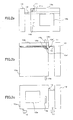
- FIGS. 2a-2c illustrate the structure of the safety door 10, showing rear, plan, and front views, respectively, of the safety door 10.
- the safety door 10 is composed of a primary safety door 10a that covers the front and the top of the clamping unit 1 of the injection molding machine and opens and closes, and a secondary safety door 10b that covers the rear of the clamping unit 1 and opens and closes.
- the primary safety door 10a and the secondary safety door 10b can be freely opened and closed independently.
- these two safety doors 10a, 10b can be moved together as a single body by an engaging means 11.
- FIGS. 2a-2c both the primary safety door 10a and the secondary safety door 10b are shown partially open.
- a guide member 12 that guides a roller 11c of the engaging means 11 in a direction in which the secondary safety door 10b opens and closes is located on the rear side of the clamping unit 1 of the injection molding machine.
- the guide member 12 forms a type of cam surface with respect to the roller 11c, such that, where the secondary safety door 10b is closed shut, the roller 11c guide surface is lowered.
- 14a is a handle for opening and closing the primary safety door 10a and 14b is a handle for opening and closing the secondary safety door 10b.
- Reference numerals 15a, 15b denote transparent windows provided on the primary safety door 10a and the secondary safety door 10b for looking therethrough into the interior.
- reference numerals 16, 17 denote detection switches for detecting opening and closing of the primary safety door 10a. That the detection switches 16, 17 are provided only for the primary safety door 10a represents an effort to reduce costs.
- Reference numeral 13 denotes a stationary platen cover.
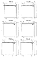
- FIGS. 3a-3f are drawings illustrating the construction of the engaging means and opening and closing operations of the safety door 10.
- FIGS. 4a-4f show states of the primary safety door 10a and the secondary safety door 10b corresponding to the opening and closing operations of the safety door 10 shown in FIGS. 3a-3f .
- the secondary safety door 10b has a projection 10b' bent inward from a top end of the closed side of the secondary safety door 10b, and a notched portion 10a' is provided in a top side member of the primary safety door 10a at a position corresponding to the projection 10b' (see FIG. 2b ).
- a face of the notched portion 10a' is an abutting portion (first abutting portion) 18a that a stopper 18b abuts.
- the stopper 18b (second abutting portion) that abuts the abutting portion of the primary safety door 10a and is made of an elastic body such as rubber is provided on the projection 10b' of the secondary safety door 10b.
- An engaging portion 19 that engages the engaging means 11 to move the primary safety door 10a and the sec as a single body is formed on the notched portion 10a' of the primary safety door 10a.
- the engaging means 11 is composed of a lever 11a swingingly supported by a lever rotation supporter 11b provided on the projection 10b' of the secondary safety door 10b, the roller 11c rotatably supported at an end of the lever 11a and guided by the guide member 12, and a hinge member 11d.
- the hinge member 11d in FIG. 3a , is urged clockwise about a hinge center of rotation 11e by urging means such as a spring, such that the rotation of the hinge member 11d is stopped at a rotation position projecting from the lever 11a and the hinge member 11d cannot rotate any further. Accordingly, the hinge member 11d cannot rotate any further in the clockwise direction in FIG. 3a from the protruding position shown in FIG. 3a , though it is capable of rotating counterclockwise against the force of the urging means such as a spring.
- FIG. 3a and FIG. 4a show a state in which both the primary safety door 10a and the secondary safety door 10b are closed.
- the weight of the lever 11a and the roller 11c causes the lever 11a of the engaging member 11 to swing about the lever rotation supporter 11b so as to create a state in which the roller 11c abuts the lowered guide surface of the guide member 12 at a low position.
- the hinge member 11d of the engaging means 11 and the engaging portion 19 of the primary safety door 10a do not engage, and as shown in FIG. 3b and FIG. 4b , the primary safety door 10a alone can be freely opened and closed separately.
- the secondary safety door 10b is closed shut, the primary safety door 10a can be freely opened and closed separately from the secondary safety door 10b.
- the first abutting portion 18a that is the base of the engaging portion 19 and the stopper (second abutting portion) 18b abut each other (the state shown in FIG. 3c ) and the secondary safety door 10b also moves in the closing direction.
- the stopper (second abutting portion) 18b pushes the first abutting portion 18a of the primary safety door 10a (the state shown in FIG. 3c ), moving the primary safety door 10a in the opening direction.
- the hinge member 11d and the engaging portion 19 abut each other (the state shown in FIG. 3d ) and, since the hinge member 11 cannot rotate further in the clockwise direction from the protruding position, the hinge member 11d pushes the engaging portion 19 and moves the primary safety door 10a in the closing direction.
- the other safety door also opens and closes, so that the primary safety door 10a and the secondary safety door 10b move as a single body and open and close.
- the primary safety door 10a When the primary safety door 10a is operated so as to open as shown in FIG. 3b and FIG. 4b from the state in which both the primary safety door 10a and the secondary safety door 10b are closed as shown in FIG. 3a and FIG. 4a , since the engaging portion 19 is not present between the hinge member 11d and the stopper 18b, the primary safety door 10a can be freely opened and closed independently of the secondary safety door 10b.
- the secondary safety door 10b is operated from the state shown in FIG. 3b and FIG. 4b , as shown in FIG. 3e and FIG. 4e , in a range in which the hinge member 11d and the engaging portion 19 do not abut each other, the secondary safety door 10b can be freely opened and closed independently of the primary safety door 10a.
- the primary safety door 10a and the secondary safety door 10b can be moved separately and opened and closed, and the primary safety door 10a and the secondary safety door 10b can be moved as a single body and the doors opened and closed.
- the primary safety door 10a and the secondary safety door 10b are coupled by the engaging means 11, and therefore when the safety door being operated is stopped the other safety door also stops, such that the safety door on the side that is not being operated does not continue to move under inertia and therefore safety can be achieved.
- hinge member 11d is provided on the engaging means 11 and the engaging portion 19 is provided on the primary safety door 10a, alternatively these may be reversed, with the hinge member 11d provided on the primary safety door 10a and the engaging portion 19 provided on the engaging means 11.
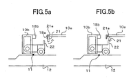
- FIGS. 5a and 5b illustrate another aspect of the engaging means of the embodiment, that is, an example of the reversal described above.
- a swingable member 21 similar to the hinge member 11d described above is provided on the primary safety door 10a, with a projection 22 that engages the swingable member 21 provided on the engaging means 11. Then, the swingable member 21 is urged to the state shown in FIG. 5a , either under its own weight or by urging means such as a spring. Although the swingable member 21 can rotate about an axis 21a in a direction indicated by an arrow in FIG. 5a , it cannot rotate in the reverse direction. As a result, as shown in FIG.
Landscapes
- Engineering & Computer Science (AREA)
- Mechanical Engineering (AREA)
- Manufacturing & Machinery (AREA)
- Injection Moulding Of Plastics Or The Like (AREA)
- Wing Frames And Configurations (AREA)
- Moulds For Moulding Plastics Or The Like (AREA)
Abstract
Description
- The present invention relates to a safety door device provided on a mold clamping unit of an injection molding machine.
- In an injection molding machine, a clamping unit moves a movable mold mounted on a movable platen against a stationary mold mounted on a stationary platen, closes the molds, and injects resin into the molds, after which the clamping unit is moved, the molds opened, and the molded article removed. When mounting the molds on the clamping unit, when performing maintenance on the clamping unit, and further, when removing the molded article manually, it is necessary to be able to access the clamping unit from the outside. However, since the clamping unit is designed to open and close the molds, there is a risk of an operator getting a hand caught in the molds. Accordingly, as a precaution a safety door is provide on the clamping unit and configured in such a way that the clamping unit can only move when the safety door has closed the clamping unit.
- Usually, a safety door is provided on both a front side, that is, an operation side where an operator mainly operates, and a rear side opposite the front side of the clamping unit. In order to ensure safety, it is necessary to provide switches that detect opening and closing of the safety doors on both the operation side safety door and the safety door on the side opposite the operation side. In order to prevent an increase in cost brought about by providing detection switches for each of the safety doors, some injection molding machines integrate the operation side safety door and the safety door on the side opposite the operation side into a single body, thus reducing the number of detection switches. However, such a single body structure increases the mass of the safety door, which is undesirable in that the safety door is opened and closed repeatedly when removing molded articles from the mold manually and thus imposes an undue burden on the operator.
- Consequently, in an attempt to provide safety while at the same time reducing the burden on the operator, safety doors in which the operation side safety door can be opened and closed independently of the rear door are known.
- For example, a safety door construction is known in which a rotary shaft is provided between the operation side safety door and the safety door on the side opposite the operation side, such that, when the operation side safety door is locked, the rotary shaft cannot rotate and thus the safety door on the side opposite the operation side cannot be opened. When the operation side safety door is not locked, the operation side safety door can be freely opened and closed. However, when the safety door on the side opposite the operation side is opened, the rotary shaft rotates, opening the operation side safety door a predetermined distance only, and when the safety door on the side opposite the operation side is open the operation side safety door is always open, and further, only when the safety door on the side opposite the operation side is closed can the operation side safety door be completely closed (see, for example,
JP2002-187184A - Moreover, a safety door construction is also known in which brackets are projected from each of the operation side safety door and the safety door on the side opposite the operation side, respectively, the bracket from the safety door on the side opposite the operation side is disposed rearward of the bracket of the operation side safety door (on a side at which the door closes), such that, when the operation side safety door is closed the safety door on the side opposite the operation side also closes. The operation side safety door can be opened independently, but when the safety door on the side opposite the operation side is opened the operation side safety door also opens order to ensure safety (see
JP55-58321U - Further, an invention in which a coupling mechanism that links the operation side safety door and the safety door on the side opposite the operation side together manually, such that when the operation side safety door and the safety door on the side opposite the operation side are coupled by the coupling mechanism both safety doors move together, and when the coupling is released both doors can be freely opened and closed independently, is also known (
JP64-36425A - Arrangements in which, in an injection molding machine having a operation side safety door and a safety door on the side opposite the operation side, when the operation side safety door can be freely opened and closed independently, and further, when the operation side safety door is shut, the safety door on the side opposite the operation side also is always shut as well in order to provide safety, and at the same time reduce the burden on the operator, are well known as described above. However, there are drawbacks to the abovedescribed approaches.
- For example, in the invention described in
JP2002-187184A - In addition, in the invention described in
JP55-58321U - In the invention described in
JP64-36425A - The present invention provides a safer safety door device of an injection molding machine without increasing costs, and further, without increasing the burden on the operator.
- A safety door device of the present invention comprises: a primary safety door provided slidably to be opened/closed on a front side of an injection molding machine and having a first abutting member; a secondary safety door provided slidably to be opened/closed on a rear side of the injection molding machine and having a second abutting member, the first and second abutting members being abutting each other when the secondary safety door is opened so that the primary safety door opens together with the secondary safety door, and the first and second abutting members being abutting each other when the primary safety door is closed so that the secondary safety door closes together with the primary safety door; an engaging portion provided at the primary safety door; and an engaging member provided at the secondary safety door that engages/disengages with the engaging portion of the primary safety door, the engaging member being in a state unable to engage with the engaging portion when the secondary safety door is closed and being in a state able to engage with the engaging portion when the secondary safety door is opened, wherein the primary safety door and the secondary safety door are coupled with each other by engagement of the engaging member and the engaging portion when the first abutting member is brought closer to the second abutting member within a predetermined distance, with the engaging member being in the state able to engage with the engaging portion.
- A guide member for guiding the engaging member may be provided in a sliding direction of the secondary safety door, so that the engaging member is brought into the state unable to engage with the engaging portion and the state able to engage with the engaging portion as guided by the guide member.
- The engaging member may comprise a lever that swings as guided by the guide member and a hinge provided at a distal end of the lever to swing to a protruding position by an urging force. In this arrangement, the hinge is swung by the engaging portion to pass the engaging portion when the first abutting member is moved relative to the second abutting member in a direction to abut each other, and is not swung by the engaging portion that is passed by the hinge when the first abutting member is move relative to the second abutting member in a direction remote from each other, with the engaging member in the state able to engage with the engaging portion.
- The engaging member may comprise a lever that swings as guided by the guide member and a projection provided at a distal end of the lever, and the engaging portion may comprise a swingable member that swings to a protruding position by an urging force. In this arrangement, the swingable member is swung by the projection to pass the projection when the first abutting member is move relative to the second abutting member in a direction to abut each other, and is not swung by the projection that is passed by the swingable member when the first abutting member is moved relative to the second abutting member in a direction remote from each other, with the engaging member in the state able to engage with the engaging portion.
- When the secondary safety door is closed shut, the primary safety door can be freely opened and closed independently of the secondary safety door so that there is no great burden on the operator. When the secondary safety door is open, the primary safety door is always open to provide safety. Further, both the primary safety door and the secondary safety door can be opened and closed separately; alternatively, the primary safety door and the secondary safety door can be moved together as a single body. In addition, if the primary safety door is closed shut then the secondary safety door is also always closed shut, and if the secondary safety door is opened in a state in which both the primary safety door and the secondary safety door are closed shut, the primary safety door opens, and further, in this case, the primary safety door and the secondary safety door are coupled together and move as a single body. Therefore, the primary safety door, which is not being operated, does not continue to move by itself under inertia, and the operation of the primary safety door can also be controlled by operation of the secondary safety door so that safety can be achieved.
- When either the primary safety door or the secondary safety door is operated alone and both safety doors are moved, both safety doors are always coupled together and move as a single body, so that the safety door that is not being operated never becomes uncontrollable. In addition, when only one of the safety doors is moved, the moving safety door is of course one that is being operated by the operator, and therefore safety is achieved, and thus safety is attained in any case.
-
-
FIGS. 1a and 1b are schematic overall views showing plan and front views, respectively, of an injection molding machine provided with a safety door according to one embodiment of the present invention; -
FIGS. 2a-2c are structural drawings of the safety door according to one embodiment of the present invention; -
FIGS. 3a-3f are drawings illustrating a construction of engaging means and opening and closing operations of the safety door in the embodiment; -
FIGS. 4a-4f show states of the opening and closing operations of the safety door in the embodiment; and -
FIGS. 5a and 5b illustrate another aspect of the engaging means of the embodiment. -
FIGS. 1a and 1b are schematic overall views showing plan and font views, respectively, of an injection molding machine provided with a safety door according to one embodiment of the present invention. - As shown in
FIGS. 1a and 1b , aclamping unit 1 and aninjection unit 2 are placed on abase 3 of the injection molding machine. Asafety door device 10 is provided on theclamping unit 1. Thesafety door device 10 is configured so that aprimary safety door 10a is provided on an operation side (front side) and asecondary safety door 10b is provided on a side opposite the operation side (rear side), in such a way that theprimary safety door 10a and thesecondary safety door 10b slide laterally in the drawing atop thebase 3 so that thesafety doors primary safety door 10a is a safety door bent so as to open and close the front side and a top side. -
FIGS. 1a and 1b show theclamping unit 1 closed. By moving theprimary safety door 10a to the left inFIGS. 1a and 1b , the front and top are opened to enable a mold to be mounted or removed, a molded article to be removed form the mold, the clamping unit to be maintained, and so forth. In addition, by moving thesecondary safety door 10b to the left inFIGS. 1a and 1b , the rear side is opened to similarly enable various operations to be performed on theclamping unit 1. -
FIGS. 2a-2c illustrate the structure of thesafety door 10, showing rear, plan, and front views, respectively, of thesafety door 10. As noted previously, thesafety door 10 is composed of aprimary safety door 10a that covers the front and the top of theclamping unit 1 of the injection molding machine and opens and closes, and asecondary safety door 10b that covers the rear of theclamping unit 1 and opens and closes. Theprimary safety door 10a and thesecondary safety door 10b can be freely opened and closed independently. In addition, these twosafety doors means 11. InFIGS. 2a-2c , both theprimary safety door 10a and thesecondary safety door 10b are shown partially open. - A
guide member 12 that guides aroller 11c of the engaging means 11 in a direction in which thesecondary safety door 10b opens and closes is located on the rear side of theclamping unit 1 of the injection molding machine. Theguide member 12 forms a type of cam surface with respect to theroller 11c, such that, where thesecondary safety door 10b is closed shut, theroller 11c guide surface is lowered. - It should be noted that 14a is a handle for opening and closing the
primary safety door secondary safety door 10b.Reference numerals primary safety door 10a and thesecondary safety door 10b for looking therethrough into the interior. In addition,reference numerals primary safety door 10a. That the detection switches 16, 17 are provided only for theprimary safety door 10a represents an effort to reduce costs.Reference numeral 13 denotes a stationary platen cover. -
FIGS. 3a-3f are drawings illustrating the construction of the engaging means and opening and closing operations of thesafety door 10. In addition,FIGS. 4a-4f show states of theprimary safety door 10a and thesecondary safety door 10b corresponding to the opening and closing operations of thesafety door 10 shown inFIGS. 3a-3f . - The
secondary safety door 10b has aprojection 10b' bent inward from a top end of the closed side of thesecondary safety door 10b, and a notchedportion 10a' is provided in a top side member of theprimary safety door 10a at a position corresponding to theprojection 10b' (seeFIG. 2b ). A face of the notchedportion 10a' is an abutting portion (first abutting portion) 18a that astopper 18b abuts. Thestopper 18b (second abutting portion) that abuts the abutting portion of theprimary safety door 10a and is made of an elastic body such as rubber is provided on theprojection 10b' of thesecondary safety door 10b. An engagingportion 19 that engages the engaging means 11 to move theprimary safety door 10a and the sec as a single body is formed on the notchedportion 10a' of theprimary safety door 10a. - The engaging means 11 is composed of a
lever 11a swingingly supported by alever rotation supporter 11b provided on theprojection 10b' of thesecondary safety door 10b, theroller 11c rotatably supported at an end of thelever 11a and guided by theguide member 12, and ahinge member 11d. Thehinge member 11d, inFIG. 3a , is urged clockwise about a hinge center ofrotation 11e by urging means such as a spring, such that the rotation of thehinge member 11d is stopped at a rotation position projecting from thelever 11a and thehinge member 11d cannot rotate any further. Accordingly, thehinge member 11d cannot rotate any further in the clockwise direction inFIG. 3a from the protruding position shown inFIG. 3a , though it is capable of rotating counterclockwise against the force of the urging means such as a spring. -
FIG. 3a andFIG. 4a show a state in which both theprimary safety door 10a and thesecondary safety door 10b are closed. In this state, since the guide surface of theguide member 12 is low, the weight of thelever 11a and theroller 11c causes thelever 11a of the engagingmember 11 to swing about thelever rotation supporter 11b so as to create a state in which theroller 11c abuts the lowered guide surface of theguide member 12 at a low position. In this state, as shown inFIG. 3a , thehinge member 11d of the engagingmeans 11 and the engagingportion 19 of theprimary safety door 10a do not engage, and as shown inFIG. 3b andFIG. 4b , theprimary safety door 10a alone can be freely opened and closed separately. In other words, when thesecondary safety door 10b is closed shut, theprimary safety door 10a can be freely opened and closed separately from thesecondary safety door 10b. - By contrast, when the
secondary safety door 10b is opened from the state in which both theprimary safety door 10a and thesecondary safety door 10b are closed shut as shown inFIG. 3a andFIG. 4a , the stopper (second abutting portion) 18b pushes the first abuttingportion 18a, which is a base of the engaging portion 19b of the notchedportion 10a' of theprimary safety door 10a, so that theprimary safety door 10a opens together with thesecondary safety door 10b. This is the state shown inFIG. 3c andFIG. 4c . InFIG. 3c andFIG. 4c , theroller 11c of the engaging means 11 moves to the high part of theguide member 12, thelever 11a is pushed up, thehinge member 11d and the engagingportion 19 of theprimary safety door 10a engage, and further, the engagingportion 19 moves opposite the face of thesecondary safety door 10b and the stopper (second abutting portion) 18b. As a result, so long as thesecondary safety door 10b is not closed shut, if theprimary safety door 10a is operated in the direction in which theprimary safety door 10a opens, abutment of the engagingportion 19 and the hinge member 11 (the state shown inFIG. 3d ) causes thesecondary safety door 10b to open as well. If theprimary safety door 10a is operated in a direction in which theprimary safety door 10a closes, the first abuttingportion 18a that is the base of the engagingportion 19 and the stopper (second abutting portion) 18b abut each other (the state shown inFIG. 3c ) and thesecondary safety door 10b also moves in the closing direction. - Conversely, if in the state shown in
FIG. 3c andFIG. 4c thesecondary safety door 10b is operated and thesecondary safety door 10b is opened, the stopper (second abutting portion) 18b pushes the first abuttingportion 18a of theprimary safety door 10a (the state shown inFIG. 3c ), moving theprimary safety door 10a in the opening direction. If thesecondary safety door 10b is operated in the closing direction, then thehinge member 11d and the engagingportion 19 abut each other (the state shown inFIG. 3d ) and, since thehinge member 11 cannot rotate further in the clockwise direction from the protruding position, thehinge member 11d pushes the engagingportion 19 and moves theprimary safety door 10a in the closing direction. In other words, so long as thesecondary safety door 10b cannot be closed, if either theprimary safety door 10a or thesecondary safety door 10b is opened or closed, the other safety door also opens and closes, so that theprimary safety door 10a and thesecondary safety door 10b move as a single body and open and close. - When the
primary safety door 10a is operated so as to open as shown inFIG. 3b andFIG. 4b from the state in which both theprimary safety door 10a and thesecondary safety door 10b are closed as shown inFIG. 3a andFIG. 4a , since the engagingportion 19 is not present between thehinge member 11d and thestopper 18b, theprimary safety door 10a can be freely opened and closed independently of thesecondary safety door 10b. In addition, when thesecondary safety door 10b is operated from the state shown inFIG. 3b andFIG. 4b , as shown inFIG. 3e andFIG. 4e , in a range in which thehinge member 11d and the engagingportion 19 do not abut each other, thesecondary safety door 10b can be freely opened and closed independently of theprimary safety door 10a. - However, when the
primary safety door 10a or thesecondary safety door 10b is moved so that thehinge member 11d and the engagingportion 19 abut each other as shown inFIG. 3f andFIG. 4f from the state shown inFIG. 3e andFIG. 4e , since thehinge member 11d rotates in the counter-clockwise direction, thehinge member 11d is pushed over by the engagingportion 19, allowing the engagingportion 19 to pass and entering the states shown inFIG. 3d and4d or inFIG. 3c andFIG. 4c . After reaching this state, as described above, theprimary safety door 10a and thesecondary safety door 10b open and close as a single body until both are closed shut. - Thus, as described above, the
primary safety door 10a and thesecondary safety door 10b can be moved separately and opened and closed, and theprimary safety door 10a and thesecondary safety door 10b can be moved as a single body and the doors opened and closed. When the doors are moved as a single body, theprimary safety door 10a and thesecondary safety door 10b are coupled by the engagingmeans 11, and therefore when the safety door being operated is stopped the other safety door also stops, such that the safety door on the side that is not being operated does not continue to move under inertia and therefore safety can be achieved. - It should be noted that although in the embodiment described above the
hinge member 11d is provided on the engagingmeans 11 and the engagingportion 19 is provided on theprimary safety door 10a, alternatively these may be reversed, with thehinge member 11d provided on theprimary safety door 10a and the engagingportion 19 provided on the engagingmeans 11. -
FIGS. 5a and 5b illustrate another aspect of the engaging means of the embodiment, that is, an example of the reversal described above. Aswingable member 21 similar to thehinge member 11d described above is provided on theprimary safety door 10a, with aprojection 22 that engages theswingable member 21 provided on the engagingmeans 11. Then, theswingable member 21 is urged to the state shown inFIG. 5a , either under its own weight or by urging means such as a spring. Although theswingable member 21 can rotate about anaxis 21a in a direction indicated by an arrow inFIG. 5a , it cannot rotate in the reverse direction. As a result, as shown inFIG. 5b , when theprimary safety door 10a and thesecondary safety door 10b are moved and theswingable member 21 moves from right to left in the drawing with respect to theprojection 22, theswingable member 21 rotates and rides up over theprojection 22. If theswingable member 21 rides up over theprojection 22 and gets between theprojection 22 and thesecondary safety door 10b (thestopper 18b), then theswingable member 21 does not rotate even when it abuts the engaging portion 22 (the projection 22) and thus theprimary safety door 10a and thesecondary safety door 10b are coupled together and move as a single body. The remaining operations are the same as those described above with reference toFIGS. 3a-3f .
Claims (4)
- A safety door device of an injection molding machine, comprising:a primary safety door provided slidably to be opened/closed on a front side of the injection molding machine and having a first abutting member;a secondary safety door provided slidably to be opened/closed on a rear side of the injection molding machine and having a second abutting member, said first and second abutting members being abutting each other when said secondary safety door is opened so that said primary safety door opens together with said secondary safety door, and said first and second abutting members being abutting each other when said primary safety door is closed so that said secondary safety door closes together with said primary safety door;an engaging portion provided at said primary safety door; andan engaging member provided at said secondary safety door that engages/disengages with said engaging portion of said primary safety door, said engaging member being in a state unable to engage with said engaging portion when said secondary safety door is closed and being in a state able to engage with said engaging portion when said secondary safety door is opened,wherein said primary safety door and said secondary safety door are coupled with each other by engagement of said engaging member and said engaging portion when said first abutting member is brought closer to said second abutting member within a predetermined distance, with said engaging member being in the state able to engage with said engaging portion.
- A safety door device of an injection molding machine according to claim 1, wherein a guide member for guiding said engaging member is provided in a sliding direction of said secondary safety door, and said engaging member is brought into the state unable to engage with said engaging portion and the state able to engage with said engaging portion as guided by said guide member.
- A safety door device of an injection molding machine according to claim 2, wherein said engaging member comprises a lever that swings as guided by said guide member and a hinge provided at a distal end of said lever to swing to a protruding position by an urging force, and said hinge is swung by said engaging portion to pass said engaging portion when said first abutting member is moved relative to said second abutting member in a direction to abut each other, and is not swung by said engaging portion that is passed by the hinge when said first abutting member is move relative to said second abutting member in a direction remote from each other, with said engaging member in the state able to engage with the engaging portion.
- A safety door device of an injection molding machine according to claim 2, wherein said engaging member comprises a lever that swings as guided by said guide member and a projection provided at a distal end of said lever, said engaging portion comprises a swingable member that swings to a protruding position by an urging force, and said swingable member is swung by said projection to pass said projection when said first abutting member is move relative to said second abutting member in a direction to abut each other, and is not swung by said projection that is passed by the swingable member when said first abutting member is moved relative to said second abutting member in a direction remote from each other, with said engaging member in the state able to engage with said engaging portion.
Applications Claiming Priority (1)
| Application Number | Priority Date | Filing Date | Title |
|---|---|---|---|
| JP2007026021A JP4185141B2 (en) | 2007-02-05 | 2007-02-05 | Injection molding machine safety door |
Publications (2)
| Publication Number | Publication Date |
|---|---|
| EP1952967A1 true EP1952967A1 (en) | 2008-08-06 |
| EP1952967B1 EP1952967B1 (en) | 2014-12-03 |
Family
ID=39428058
Family Applications (1)
| Application Number | Title | Priority Date | Filing Date |
|---|---|---|---|
| EP20080100502 Active EP1952967B1 (en) | 2007-02-05 | 2008-01-15 | Safety door device of injection molding machine |
Country Status (4)
| Country | Link |
|---|---|
| US (1) | US7540736B2 (en) |
| EP (1) | EP1952967B1 (en) |
| JP (1) | JP4185141B2 (en) |
| CN (1) | CN101239501B (en) |
Families Citing this family (7)
| Publication number | Priority date | Publication date | Assignee | Title |
|---|---|---|---|---|
| WO2008091876A1 (en) * | 2007-01-22 | 2008-07-31 | Novavision, Inc. | Device for treating human vision using combined optical and electrical stimulation |
| AT511231B1 (en) | 2011-03-18 | 2014-08-15 | Engel Austria Gmbh | PROTECTIVE COVER FOR AN INJECTION MOLDING MACHINE |
| AT514426B1 (en) * | 2013-10-11 | 2015-01-15 | Engel Austria Gmbh | Handling device or forming machine |
| DE102015101852B3 (en) * | 2015-02-10 | 2016-03-03 | Zhafir Plastics Machinery Gmbh | Protective device for an injection molding machine |
| JP6325503B2 (en) * | 2015-10-26 | 2018-05-16 | ファナック株式会社 | Sliding door bounce suppression mechanism |
| JP6705868B2 (en) * | 2018-07-11 | 2020-06-03 | ファナック株式会社 | Injection molding machine |
| JP2023048344A (en) * | 2021-09-28 | 2023-04-07 | セイコーエプソン株式会社 | injection molding system |
Citations (4)
| Publication number | Priority date | Publication date | Assignee | Title |
|---|---|---|---|---|
| JPS5558321U (en) | 1978-10-13 | 1980-04-21 | ||
| JPS6436425A (en) | 1987-08-03 | 1989-02-07 | Japan Steel Works Ltd | Safety door device of injection molding machine |
| JPH0699469A (en) * | 1992-09-22 | 1994-04-12 | Niigata Eng Co Ltd | Safety device for injection molder |
| JP2002187184A (en) | 2000-12-21 | 2002-07-02 | Toshiba Mach Co Ltd | Safety device for safety door of injection molding machine |
Family Cites Families (4)
| Publication number | Priority date | Publication date | Assignee | Title |
|---|---|---|---|---|
| JPH0536018Y2 (en) | 1987-08-28 | 1993-09-13 | ||
| US5017121A (en) * | 1987-12-30 | 1991-05-21 | Karl Hehl | Injection molding machine comprising a protective covering |
| US5192557A (en) * | 1990-07-27 | 1993-03-09 | Nissei Jushi Kogyo K.K. | Clamping apparatus for molding machine |
| CN2752022Y (en) * | 2004-07-01 | 2006-01-18 | 广州博创机械有限公司 | Safety door positioning device for injection machine |
-
2007
- 2007-02-05 JP JP2007026021A patent/JP4185141B2/en active Active
-
2008
- 2008-01-15 EP EP20080100502 patent/EP1952967B1/en active Active
- 2008-01-20 US US12/017,036 patent/US7540736B2/en active Active
- 2008-02-01 CN CN2008100094215A patent/CN101239501B/en active Active
Patent Citations (4)
| Publication number | Priority date | Publication date | Assignee | Title |
|---|---|---|---|---|
| JPS5558321U (en) | 1978-10-13 | 1980-04-21 | ||
| JPS6436425A (en) | 1987-08-03 | 1989-02-07 | Japan Steel Works Ltd | Safety door device of injection molding machine |
| JPH0699469A (en) * | 1992-09-22 | 1994-04-12 | Niigata Eng Co Ltd | Safety device for injection molder |
| JP2002187184A (en) | 2000-12-21 | 2002-07-02 | Toshiba Mach Co Ltd | Safety device for safety door of injection molding machine |
Also Published As
| Publication number | Publication date |
|---|---|
| CN101239501B (en) | 2011-02-02 |
| CN101239501A (en) | 2008-08-13 |
| US7540736B2 (en) | 2009-06-02 |
| JP2008188886A (en) | 2008-08-21 |
| EP1952967B1 (en) | 2014-12-03 |
| US20080263961A1 (en) | 2008-10-30 |
| JP4185141B2 (en) | 2008-11-26 |
Similar Documents
| Publication | Publication Date | Title |
|---|---|---|
| EP1952967B1 (en) | Safety door device of injection molding machine | |
| US11781367B2 (en) | Vehicle door opening and closing apparatus | |
| CN110712347B (en) | Injection molding machine | |
| CN104750197A (en) | Door mechanism and electronic device for case | |
| EP2977180B1 (en) | Link mechanism for opening and closing die and positioning bottom die by single shaft | |
| KR20140089085A (en) | Door hindge hindge a function of door checker | |
| KR101145970B1 (en) | a door closing supporting apparatus | |
| US20170342751A1 (en) | Opening control device | |
| US4162878A (en) | Safety latch system | |
| JP5130390B1 (en) | Start control machine with automatic return mechanism from released state | |
| JP2008280752A (en) | Latch lock | |
| KR102200062B1 (en) | Covering structure of charging port for vehicle | |
| JP6071891B2 (en) | Safety device for molding machine | |
| JP2025176741A (en) | Safety devices used in safety doors of injection molding machines, etc. | |
| JP3927431B2 (en) | Door shock absorber | |
| JPH0647106Y2 (en) | Door opening / closing device that can be opened left and right | |
| WO2016103309A1 (en) | Door closer | |
| JP2668342B2 (en) | Door stop holding device | |
| KR101540351B1 (en) | Globe box | |
| JP5968168B2 (en) | Start control machine with release lock mechanism and return mechanism | |
| JP6114650B2 (en) | Door closer | |
| JP2744930B2 (en) | Opening and closing stay | |
| JP6576270B2 (en) | Opening restriction device and joinery | |
| JPH0790583B2 (en) | Injection molding machine | |
| JP2001152725A (en) | Cover opening/closing part structure of electric equipment |
Legal Events
| Date | Code | Title | Description |
|---|---|---|---|
| PUAI | Public reference made under article 153(3) epc to a published international application that has entered the european phase |
Free format text: ORIGINAL CODE: 0009012 |
|
| AK | Designated contracting states |
Kind code of ref document: A1 Designated state(s): AT BE BG CH CY CZ DE DK EE ES FI FR GB GR HR HU IE IS IT LI LT LU LV MC MT NL NO PL PT RO SE SI SK TR |
|
| AX | Request for extension of the european patent |
Extension state: AL BA MK RS |
|
| 17P | Request for examination filed |
Effective date: 20080711 |
|
| AKX | Designation fees paid |
Designated state(s): DE |
|
| RAP1 | Party data changed (applicant data changed or rights of an application transferred) |
Owner name: FANUC CORPORATION |
|
| GRAP | Despatch of communication of intention to grant a patent |
Free format text: ORIGINAL CODE: EPIDOSNIGR1 |
|
| INTG | Intention to grant announced |
Effective date: 20140716 |
|
| GRAS | Grant fee paid |
Free format text: ORIGINAL CODE: EPIDOSNIGR3 |
|
| GRAA | (expected) grant |
Free format text: ORIGINAL CODE: 0009210 |
|
| AK | Designated contracting states |
Kind code of ref document: B1 Designated state(s): DE |
|
| REG | Reference to a national code |
Ref country code: DE Ref legal event code: R096 Ref document number: 602008035642 Country of ref document: DE Effective date: 20150115 |
|
| REG | Reference to a national code |
Ref country code: DE Ref legal event code: R097 Ref document number: 602008035642 Country of ref document: DE |
|
| PLBE | No opposition filed within time limit |
Free format text: ORIGINAL CODE: 0009261 |
|
| STAA | Information on the status of an ep patent application or granted ep patent |
Free format text: STATUS: NO OPPOSITION FILED WITHIN TIME LIMIT |
|
| 26N | No opposition filed |
Effective date: 20150904 |
|
| PGFP | Annual fee paid to national office [announced via postgrant information from national office to epo] |
Ref country code: DE Payment date: 20241218 Year of fee payment: 18 |