EP1952746A2 - Vacuum hose attachment - Google Patents
Vacuum hose attachment Download PDFInfo
- Publication number
- EP1952746A2 EP1952746A2 EP08101164A EP08101164A EP1952746A2 EP 1952746 A2 EP1952746 A2 EP 1952746A2 EP 08101164 A EP08101164 A EP 08101164A EP 08101164 A EP08101164 A EP 08101164A EP 1952746 A2 EP1952746 A2 EP 1952746A2
- Authority
- EP
- European Patent Office
- Prior art keywords
- vacuum
- vacuum appliance
- accessory
- attachment
- intake port
- Prior art date
- Legal status (The legal status is an assumption and is not a legal conclusion. Google has not performed a legal analysis and makes no representation as to the accuracy of the status listed.)
- Withdrawn
Links
Images



Classifications
-
- A—HUMAN NECESSITIES
- A47—FURNITURE; DOMESTIC ARTICLES OR APPLIANCES; COFFEE MILLS; SPICE MILLS; SUCTION CLEANERS IN GENERAL
- A47L—DOMESTIC WASHING OR CLEANING; SUCTION CLEANERS IN GENERAL
- A47L9/00—Details or accessories of suction cleaners, e.g. mechanical means for controlling the suction or for effecting pulsating action; Storing devices specially adapted to suction cleaners or parts thereof; Carrying-vehicles specially adapted for suction cleaners
- A47L9/24—Hoses or pipes; Hose or pipe couplings
- A47L9/242—Hose or pipe couplings
-
- A—HUMAN NECESSITIES
- A47—FURNITURE; DOMESTIC ARTICLES OR APPLIANCES; COFFEE MILLS; SPICE MILLS; SUCTION CLEANERS IN GENERAL
- A47L—DOMESTIC WASHING OR CLEANING; SUCTION CLEANERS IN GENERAL
- A47L9/00—Details or accessories of suction cleaners, e.g. mechanical means for controlling the suction or for effecting pulsating action; Storing devices specially adapted to suction cleaners or parts thereof; Carrying-vehicles specially adapted for suction cleaners
-
- A—HUMAN NECESSITIES
- A47—FURNITURE; DOMESTIC ARTICLES OR APPLIANCES; COFFEE MILLS; SPICE MILLS; SUCTION CLEANERS IN GENERAL
- A47L—DOMESTIC WASHING OR CLEANING; SUCTION CLEANERS IN GENERAL
- A47L9/00—Details or accessories of suction cleaners, e.g. mechanical means for controlling the suction or for effecting pulsating action; Storing devices specially adapted to suction cleaners or parts thereof; Carrying-vehicles specially adapted for suction cleaners
- A47L9/02—Nozzles
-
- F—MECHANICAL ENGINEERING; LIGHTING; HEATING; WEAPONS; BLASTING
- F16—ENGINEERING ELEMENTS AND UNITS; GENERAL MEASURES FOR PRODUCING AND MAINTAINING EFFECTIVE FUNCTIONING OF MACHINES OR INSTALLATIONS; THERMAL INSULATION IN GENERAL
- F16L—PIPES; JOINTS OR FITTINGS FOR PIPES; SUPPORTS FOR PIPES, CABLES OR PROTECTIVE TUBING; MEANS FOR THERMAL INSULATION IN GENERAL
- F16L37/00—Couplings of the quick-acting type
- F16L37/24—Couplings of the quick-acting type in which the connection is made by inserting one member axially into the other and rotating it to a limited extent, e.g. with bayonet-action
- F16L37/244—Couplings of the quick-acting type in which the connection is made by inserting one member axially into the other and rotating it to a limited extent, e.g. with bayonet-action the coupling being co-axial with the pipe
- F16L37/252—Couplings of the quick-acting type in which the connection is made by inserting one member axially into the other and rotating it to a limited extent, e.g. with bayonet-action the coupling being co-axial with the pipe the male part having lugs on its periphery penetrating into the corresponding slots provided in the female part
Definitions
- the present disclosure relates to vacuum accessory locks. More specifically, the present disclosure relates to an attachment and locking mechanism for interchangeable vacuum accessories.
- Vacuum appliances originated in the late 1800s and are now the most commonly used tool for picking up both wet and dry debris. Vacuum appliances may be found in various configurations, including household or industrial vacuum cleaners (bag, cyclonic or robotic), central vacuum cleaners, steam cleaners or wet/dry vacuum cleaners. Although design and complexity may vary, vacuum appliances are typically comprised of five components: a motor, a fan, a housing, an exhaust port and an intake port.
- an electric current is applied to the motor for rotationally driving the fan.
- the shape and design of the fan blades forces air in a single direction, typically away from the intake port and towards the exhaust port.
- the moving air causes a pressure drop behind the fan, generating suction.
- Suction directed at the intake port pulls debris into the vacuum housing where it is contained for later disposal.
- the air flow into the vacuum appliance is also constant.
- various media may require more suction than provided with the typical air flow.
- Suction varies with the size and shape of the intake port; therefore, different accessories can be attached to the intake port for various debris media.
- the accessories may vary the length of the intake hose for extended reach ability or shape configuration. Occasionally, it is also necessary to combine accessories to provide for even further extended reach and increased air flow.
- accessory attachment is achieved via a friction fit or a clip-type locking mechanism.
- a connection end of the accessory may be tapered, and the tapered end may be inserted into the intake port until the two parts mate.
- the friction fit between the accessory and the intake port may be relied upon to hold the accessory in place. While friction fit attachment is generally acceptable for light duty applications, it can be problematic in industrial or heavy usage situations where the attachments are prone to damage. In such applications, minor accessory damage may reduce vacuum seal, in turn causing reduced suction pressure.
- a first embodiment of the present disclosure includes a vacuum appliance having a housing with an intake port.
- a plurality of attachment nodes are axially located about the intake port.
- An accessory with a plurality of axially located grooves selectively engages the plurality of attachment nodes to establish a locking relationship with the intake port.
- An alternate embodiment of the present disclosure includes a vacuum appliance attachment mechanism for a vacuum appliance having an attached intake port with a proximal end attached to the vacuum appliance, an intermediary portion with a plurality of axially located attachment nodes and an elongated distal end.
- a vacuum accessory having a plurality of axially located spiral grooves is receivably attached to the plurality of axially located attachment nodes of the intermediary portion of the intake port.
- a vacuum appliance is depicted generally by reference number 10.
- the vacuum appliance 10 includes a housing 12 containing a motor (not shown), a fan (not shown), an intake port 14, an exhaust port 16, a filter (not shown) and a vacuum accessory 18. While Figure 1 depicts a typical wet/dry vacuum cleaner with a hose accessory 18 as the vacuum accessory, the present teachings may also be applied to other vacuum accessories and vacuum appliance configurations that utilize alternate vacuum accessories, such as, household or industrial vacuum cleaners (bag, cyclonic or robotic), central vacuum cleaners or steam cleaners.
- the motor of the vacuum appliance 10 may be provided with an electrical current by means known in the art, for example, an electrical outlet cord 20. Electric current traveling through the electrical outlet cord 20 may be applied to the motor causing it to cycle at a constant speed.
- the fan may be in electrical communication with the motor and is thereby rotationally driven by the cycling of the motor.
- the fan may have a suitable blade design which utilizes the rotational motion of the fan to create a pressure drop behind the blades forcing air in a single direction, also at a generally constant speed.
- the fan may be so situated as to cause air to flow from the intake port 14 towards the exhaust port 16. Friction between moving air particles and debris (including solids, liquids, and gases) causes the debris to enter the intake port 14. After entering the intake port 14, the debris flows into the housing 12, the filter then prevents the debris from continuing out of the exhaust port 16 with the air particles.
- the intake port 14 may be fixedly attached to the housing 12 of the vacuum appliance 10 by any means known in the art.
- the intake port 14 may be generally tubular in shape and may define an axis, A.
- a plurality of attachment nodes 22 may be located about the exterior circumference of the intake port 14 defined by axis, A. Although the number of attachment nodes 22 may vary from that shown in the present embodiment, it is advantageous to standardize the number of attachment nodes 22 for maximum interchangeability.
- the intake port 14 may further comprise an elongated distal portion 24 adjacent to the proximal portion including the attachment nodes 22.
- the elongated distal portion 24 may be smaller in diameter than said proximal portion and may provide a typical friction fit arrangement as is known in the art.
- a step portion providing a reduced diameter can be provided between the proximal and distal portions.
- the elongated portion 24 may be generally smooth and tubular and it may be tapered, for attachment to industry standard accessories.
- the hose accessory 18 may have proximal and distal ends 26, 28.
- the proximal end 26 may be generally tubular in shape and may define an axis, B.
- the proximal end 26 may comprise a plurality of spiral grooves 30 located about the interior circumference of the hose accessory 18 defined by axis, B.
- the number of spiral grooves 30 may vary from that shown in the present embodiment; however it is advantageous to standardize the number of spiral grooves 30 for maximum interchangeability. Further, the number of spiral grooves 30 should be chosen to match the number of attachment nodes 22.
- the spiral grooves 30 may open at a top surface 32 of the proximal end 26 of the hose accessory 18 and rotate around axis, B, towards the distal end 28 at an angle, ⁇ 1 .
- the angle, ⁇ 1 may be between 30 degrees and 60 degrees, and as shown can be approximately 45 degrees.
- the spiral grooves 30 may end in a generally straight portion (i.e. not spiral) 34, which is parallel to the top
- Attachment of the hose accessory 18 to the intake port 14 of the vacuum appliance 10 is accomplished by aligning the attachment nodes 22 with the spiral grooves 30 at the open top surface 32 of the proximal end 26 of the hose accessory 18.
- the hose accessory 18 is then rotated in a counter-clockwise motion (shown by rotational arrow) with respect to the attachment nodes 22 of the intake port 14 until the attachment nodes 22 reach the generally straight portion 34 of the spiral grooves 30.
- the attachment nodes 22 reach the generally straight portion 34
- the hose accessory 18 is cammed into engagement with the intake port 14 and a vacuum tight seal is created between the hose accessory 18 and the intake port 14. Rotation of the hose accessory 18 in a clockwise motion assists in releasing this vacuum tight seal.
- the distal end 28 of the hose accessory 18 may be generally tubular in shape and may define an axis, C.
- the distal end of the hose can define an intake port to the vacuum appliance.
- the distal end 28 of the hose accessory 18 may comprise a plurality of attachment nodes 22', which may be located about the exterior circumference of the distal end 28 defined by axis, C.
- the number of attachment nodes 22' may vary from that shown in the present embodiment; however it is advantageous to standardize the number of attachment nodes 22' for maximum interchangeability.
- the distal end 28 of the hose accessory 18 may further comprise an elongated portion 24' adjacent to the attachment nodes 22'.
- the elongated portion 24' may be a typical friction fit arrangement as is known in the art.
- the elongated portion 24' may be generally smooth and tubular or it may be tapered, for attachment to current industry standard accessories.
- the distal end 28 of the hose accessory 18 may accept a proximal end 36 of another vacuum accessory, as shown in Figure 4 as a nozzle accessory 38.
- the configuration of the proximal end 36 in the nozzle accessory 38 may be similar to that described for the hose accessory 18 (including interior spiral grooves 30'), but may incorporate an alternately configured proximal end 40 for performing alternate tasks.
- the alternate vacuum accessory 38 may be configured with any proximal end 40 configuration known in the art, such as an upholstery brush, a dusting brush, a crevice tool, or an extension wand. Attachment between the vacuum accessories 18, 38 is identical to the attachment between the intake port 14 and the hose accessory 18.
- vacuum accessories 18, 38 may be connected as described herein or may also be typical industry standard, friction fit accessories attached to the elongated portion 24' of the hose accessory 18 as described herein.
- an inlet port 114 of the vacuum appliance 110 may be connected to a hose accessory 118 via a soft interface as shown in Figure 6 .
- the soft interface may be an o-ring 142.
- the o-ring 142 may be seated in a groove 144 provided in the outward facing surface of the inlet port 114.
- the o-ring 142 may be fabricated from a material (i.e. an elastomeric material) that resumes its original shape when a deforming force is removed.
- the hardness rating on a Shore A scale for the o-ring 142 may be greater than 40 durometer. In the example embodiment, the hardness rating on a Shore A scale for the o-ring 142 may be in the range of 65-75 durometer.
- the o-ring 142 may extend outward beyond the outer surface of the inlet port 114, and have an outer diameter that is greater than an inner diameter of the hose accessory 118. Also, the inner diameter of the hose accessory 118 may be greater than the outer diameter of the inlet port 114. Accordingly, the o-ring 142 may be compressed when the hose accessory 118 is mounted, creating a seal at the interface. At the same time, the o-ring 142 may maintain a clearance between the hose accessory 118 and the inlet port 114. In this way, the o-ring 142 may absorb impacts at the joint between the hose accessory 118 and the inlet port 114.
- the soft interface provided by the o-ring 142 may be implemented without any additional connecting structures (e.g., a locking member or other non-pliant structures).
- the o-ring 142 may have a round cross-sectional shape. In alternative embodiments, the o-ring 142 may have numerous and varied cross-sectional shapes.
- the inlet port 114 and the hose accessory 118 may be cylindrically shaped. In alternative embodiments, the inlet port 114 and the hose accessory 118 may have corresponding tapered shapes.
- the o-ring 242 may be seated in a groove 244 provided in the inward facing surface of the inlet port 214. As shown, the o-ring 242 may extend inward beyond the inner surface of the inlet port 214, and have an inner diameter that is greater than an outer diameter of the hose accessory 218. Also, the inner diameter of the inlet port 214 may be greater than the outer diameter of the hose accessory 218. Accordingly, the o-ring 242 may be compressed when the hose accessory 218 is mounted, creating a seal at the interface. At the same time, the o-ring 242 may maintain a clearance between the hose accessory 218 and the inlet port 214.
- the o-ring 342 may be seated in a groove 344 provided in the outward facing surface of the inlet port 314. As shown, the o-ring 342 may extend outward beyond the outer surface of the inlet port 314, and have an outer diameter that is greater than an inner diameter of the hose accessory 318. Also, the inner diameter of the hose accessory 318 may be greater than the outer diameter of the inlet port 314. Accordingly, the o-ring 342 may be compressed when the hose accessory 318 is mounted, creating a seal at the interface. At the same time, the o-ring 342 may maintain a clearance between the hose accessory 318 and the inlet port 314. The inner surface of the hose accessory 318 may include a taper 346 to facilitate mounting of the hose accessory 318.
- the o-ring 142, 242, 342 may be seated in the groove 144, 244, 344 provided on an inner diameter of the inlet port 114, 214, 314.
- the o-ring may be seated in a groove provided in a surface of the hose. It will be readily apparent that the example embodiments may implement one or more o-rings. It will also be readily apparent that the inlet port may be provided in the housing 12 of the vacuum appliance 10.
- the housing 12 of the vacuum appliance 10 may support an adaptor 400, which may include an inlet port 414 for connection to a hose accessory 418.
- the housing 12 may include a notch 420 defined between opposed guide grooves 422.
- the adaptor 400 may be inserted into the notch 420 so that opposed edge portions of the adaptor 400 enter into (and are guided by) the opposed guide grooves 422.
- the adaptor 400 may be situated at a location on the housing 12 that may facilitate insertion/removal.
- the insertion direction of the adaptor 400 may be perpendicular to a central axis of the inlet port 414.
- the hose accessory 418 may he inserted into the inlet port 414 until the two parts mate.
- the friction-fit between the inlet port 414 and the hose accessory 418 may hold the hose accessory 418 in place.
- the adaptor 400 may be fabricated from a material (i.e. an elastomeric material) that resumes its original shape when a deforming force is removed. Thus, the adaptor 400 may offer a soft interface feature by which impacts at the joint between the hose accessory 418 and the inlet port 414 may be absorbed.
- the adaptor 400 may be fabricated from a material that provides sufficient hose support and shock absorbing characteristics.
- the hardness rating on a Shore A scale for the adaptor 400 may be greater than 40 durometer. In the example embodiment, the hardness rating on a Shore A scale for the adaptor 400 may be in the range of 65-75 durometer.
- the hardness of the adaptor 400 may be less than the hardness of the housing 12 and the hardness of the hose accessory 418. However, the hardness of the adaptor 400 may depend on the structural details of the adaptor 400 and/or the detail of the surrounding structure.
Landscapes
- Engineering & Computer Science (AREA)
- Mechanical Engineering (AREA)
- General Engineering & Computer Science (AREA)
- Electric Vacuum Cleaner (AREA)
- Hooks, Suction Cups, And Attachment By Adhesive Means (AREA)
Abstract
Description
- The present disclosure relates to vacuum accessory locks. More specifically, the present disclosure relates to an attachment and locking mechanism for interchangeable vacuum accessories.
- The statements in this section merely provide background information related to the present disclosure and may not constitute prior art.
- Vacuum appliances originated in the late 1800s and are now the most commonly used tool for picking up both wet and dry debris. Vacuum appliances may be found in various configurations, including household or industrial vacuum cleaners (bag, cyclonic or robotic), central vacuum cleaners, steam cleaners or wet/dry vacuum cleaners. Although design and complexity may vary, vacuum appliances are typically comprised of five components: a motor, a fan, a housing, an exhaust port and an intake port.
- In use, an electric current is applied to the motor for rotationally driving the fan. The shape and design of the fan blades forces air in a single direction, typically away from the intake port and towards the exhaust port. The moving air causes a pressure drop behind the fan, generating suction. Suction directed at the intake port pulls debris into the vacuum housing where it is contained for later disposal.
- Since the motor typically runs at a constant speed, the air flow into the vacuum appliance is also constant. However, various media may require more suction than provided with the typical air flow. Suction varies with the size and shape of the intake port; therefore, different accessories can be attached to the intake port for various debris media. Also, it is occasionally necessary to have an alternate vacuum appliance configuration to reach difficult locations (i.e. narrow locations, high locations, etc). The accessories may vary the length of the intake hose for extended reach ability or shape configuration. Occasionally, it is also necessary to combine accessories to provide for even further extended reach and increased air flow.
- In current industry standard applications, accessory attachment is achieved via a friction fit or a clip-type locking mechanism. In the friction fit, a connection end of the accessory may be tapered, and the tapered end may be inserted into the intake port until the two parts mate. The friction fit between the accessory and the intake port may be relied upon to hold the accessory in place. While friction fit attachment is generally acceptable for light duty applications, it can be problematic in industrial or heavy usage situations where the attachments are prone to damage. In such applications, minor accessory damage may reduce vacuum seal, in turn causing reduced suction pressure.
- While the clip-type locking mechanisms may overcome some of the friction fit problems, they usually require additional pieces. This can lead to additional cost and additional failure modes.
- Accordingly, a first embodiment of the present disclosure includes a vacuum appliance having a housing with an intake port. A plurality of attachment nodes are axially located about the intake port. An accessory with a plurality of axially located grooves selectively engages the plurality of attachment nodes to establish a locking relationship with the intake port.
- An alternate embodiment of the present disclosure includes a vacuum appliance attachment mechanism for a vacuum appliance having an attached intake port with a proximal end attached to the vacuum appliance, an intermediary portion with a plurality of axially located attachment nodes and an elongated distal end. A vacuum accessory having a plurality of axially located spiral grooves is receivably attached to the plurality of axially located attachment nodes of the intermediary portion of the intake port.
- Further areas of applicability will become apparent from the description provided herein. It should be understood that the description and specific examples are intended for purposes of illustration only and are not intended to limit the scope of the present disclosure.
- The drawings described herein are for illustration purposes only and are not intended to limit the scope of the present disclosure in any way.
-
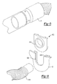
Figure 1 is a perspective view of a vacuum appliance utilizing an accessory attachment mechanism in accordance with the principles of the present teachings; -
Figure 2 is an exploded view of the accessory attachment mechanism ofFigure 1 ; -
Figure 3 is a perspective view of a hose accessory and a nozzle accessory before attachment; -
Figure 4 is a perspective view of the hose accessory and the nozzle accessory after attachment; -
Figure 5 is a perspective view of the hose accessory and a friction-fit tool accessory after attachment; -
Figure 6 is a cross-sectional view of an attachment between a hose accessory and an intake port in accordance with a second embodiment of the present teachings; -
Figure 7 is a cross-sectional view of an attachment between a hose accessory and an intake port in accordance with a third embodiment of the present teachings; -
Figure 8 is a cross-sectional view of an attachment between a hose accessory and an intake port in accordance with a fourth embodiment of the present teachings; and -
Figure 9 is a perspective view of an adaptor with an intake port for attachment with a vacuum accessory in accordance with an fifth embodiment of the present teachings. - The following description is merely exemplary in nature and is not intended to limit the present disclosure, application, or uses. It should be understood that throughout the drawings, corresponding reference numerals indicate like or corresponding parts and features.
- With reference to
Figure 1 , a vacuum appliance is depicted generally byreference number 10. Thevacuum appliance 10 includes ahousing 12 containing a motor (not shown), a fan (not shown), anintake port 14, anexhaust port 16, a filter (not shown) and avacuum accessory 18. WhileFigure 1 depicts a typical wet/dry vacuum cleaner with ahose accessory 18 as the vacuum accessory, the present teachings may also be applied to other vacuum accessories and vacuum appliance configurations that utilize alternate vacuum accessories, such as, household or industrial vacuum cleaners (bag, cyclonic or robotic), central vacuum cleaners or steam cleaners. - The motor of the
vacuum appliance 10 may be provided with an electrical current by means known in the art, for example, anelectrical outlet cord 20. Electric current traveling through theelectrical outlet cord 20 may be applied to the motor causing it to cycle at a constant speed. The fan may be in electrical communication with the motor and is thereby rotationally driven by the cycling of the motor. - The fan may have a suitable blade design which utilizes the rotational motion of the fan to create a pressure drop behind the blades forcing air in a single direction, also at a generally constant speed. The fan may be so situated as to cause air to flow from the
intake port 14 towards theexhaust port 16. Friction between moving air particles and debris (including solids, liquids, and gases) causes the debris to enter theintake port 14. After entering theintake port 14, the debris flows into thehousing 12, the filter then prevents the debris from continuing out of theexhaust port 16 with the air particles. - With reference to
Figure 2 , thehose accessory 18 is shown prior to attachment to theintake port 14. Theintake port 14 may be fixedly attached to thehousing 12 of thevacuum appliance 10 by any means known in the art. Theintake port 14 may be generally tubular in shape and may define an axis, A. A plurality ofattachment nodes 22 may be located about the exterior circumference of theintake port 14 defined by axis, A. Although the number ofattachment nodes 22 may vary from that shown in the present embodiment, it is advantageous to standardize the number ofattachment nodes 22 for maximum interchangeability. Theintake port 14 may further comprise an elongateddistal portion 24 adjacent to the proximal portion including theattachment nodes 22. The elongateddistal portion 24 may be smaller in diameter than said proximal portion and may provide a typical friction fit arrangement as is known in the art. A step portion providing a reduced diameter can be provided between the proximal and distal portions. For reference, theelongated portion 24 may be generally smooth and tubular and it may be tapered, for attachment to industry standard accessories. - The
hose accessory 18 may have proximal anddistal ends proximal end 26 may be generally tubular in shape and may define an axis, B. Theproximal end 26 may comprise a plurality ofspiral grooves 30 located about the interior circumference of thehose accessory 18 defined by axis, B. The number ofspiral grooves 30 may vary from that shown in the present embodiment; however it is advantageous to standardize the number ofspiral grooves 30 for maximum interchangeability. Further, the number ofspiral grooves 30 should be chosen to match the number ofattachment nodes 22. Thespiral grooves 30 may open at atop surface 32 of theproximal end 26 of thehose accessory 18 and rotate around axis, B, towards thedistal end 28 at an angle, α1. The angle, α1, may be between 30 degrees and 60 degrees, and as shown can be approximately 45 degrees. Thespiral grooves 30 may end in a generally straight portion (i.e. not spiral) 34, which is parallel to thetop surface 32. - Attachment of the
hose accessory 18 to theintake port 14 of thevacuum appliance 10 is accomplished by aligning theattachment nodes 22 with thespiral grooves 30 at the opentop surface 32 of theproximal end 26 of thehose accessory 18. Thehose accessory 18 is then rotated in a counter-clockwise motion (shown by rotational arrow) with respect to theattachment nodes 22 of theintake port 14 until theattachment nodes 22 reach the generallystraight portion 34 of thespiral grooves 30. When theattachment nodes 22 reach the generallystraight portion 34, thehose accessory 18 is cammed into engagement with theintake port 14 and a vacuum tight seal is created between thehose accessory 18 and theintake port 14. Rotation of thehose accessory 18 in a clockwise motion assists in releasing this vacuum tight seal. - Referring now to
Figure 3 , thedistal end 28 of thehose accessory 18 may be generally tubular in shape and may define an axis, C. The distal end of the hose can define an intake port to the vacuum appliance. Thedistal end 28 of thehose accessory 18 may comprise a plurality of attachment nodes 22', which may be located about the exterior circumference of thedistal end 28 defined by axis, C. The number of attachment nodes 22' may vary from that shown in the present embodiment; however it is advantageous to standardize the number of attachment nodes 22' for maximum interchangeability. - The
distal end 28 of thehose accessory 18 may further comprise anelongated portion 24' adjacent to the attachment nodes 22'. Theelongated portion 24' may be a typical friction fit arrangement as is known in the art. For reference, theelongated portion 24' may be generally smooth and tubular or it may be tapered, for attachment to current industry standard accessories. - As should be understood, the
distal end 28 of thehose accessory 18 may accept aproximal end 36 of another vacuum accessory, as shown inFigure 4 as anozzle accessory 38. The configuration of theproximal end 36 in thenozzle accessory 38 may be similar to that described for the hose accessory 18 (including interior spiral grooves 30'), but may incorporate an alternately configuredproximal end 40 for performing alternate tasks. It should be understood that thealternate vacuum accessory 38 may be configured with anyproximal end 40 configuration known in the art, such as an upholstery brush, a dusting brush, a crevice tool, or an extension wand. Attachment between thevacuum accessories intake port 14 and thehose accessory 18. - As
Figure 5 depicts, thevacuum accessories elongated portion 24' of thehose accessory 18 as described herein. - In another embodiment, an
inlet port 114 of the vacuum appliance 110 may be connected to ahose accessory 118 via a soft interface as shown inFigure 6 . Here, the soft interface may be an o-ring 142. The o-ring 142 may be seated in agroove 144 provided in the outward facing surface of theinlet port 114. The o-ring 142 may be fabricated from a material (i.e. an elastomeric material) that resumes its original shape when a deforming force is removed. By way of example only, the hardness rating on a Shore A scale for the o-ring 142 may be greater than 40 durometer. In the example embodiment, the hardness rating on a Shore A scale for the o-ring 142 may be in the range of 65-75 durometer. - As shown, the o-
ring 142 may extend outward beyond the outer surface of theinlet port 114, and have an outer diameter that is greater than an inner diameter of thehose accessory 118. Also, the inner diameter of thehose accessory 118 may be greater than the outer diameter of theinlet port 114. Accordingly, the o-ring 142 may be compressed when thehose accessory 118 is mounted, creating a seal at the interface. At the same time, the o-ring 142 may maintain a clearance between thehose accessory 118 and theinlet port 114. In this way, the o-ring 142 may absorb impacts at the joint between thehose accessory 118 and theinlet port 114. The soft interface provided by the o-ring 142 may be implemented without any additional connecting structures (e.g., a locking member or other non-pliant structures). - By way of example only, the o-
ring 142 may have a round cross-sectional shape. In alternative embodiments, the o-ring 142 may have numerous and varied cross-sectional shapes. Theinlet port 114 and thehose accessory 118 may be cylindrically shaped. In alternative embodiments, theinlet port 114 and thehose accessory 118 may have corresponding tapered shapes. - Another example embodiment is depicted in
Figure 7 . Here, the o-ring 242 may be seated in agroove 244 provided in the inward facing surface of theinlet port 214. As shown, the o-ring 242 may extend inward beyond the inner surface of theinlet port 214, and have an inner diameter that is greater than an outer diameter of thehose accessory 218. Also, the inner diameter of theinlet port 214 may be greater than the outer diameter of thehose accessory 218. Accordingly, the o-ring 242 may be compressed when thehose accessory 218 is mounted, creating a seal at the interface. At the same time, the o-ring 242 may maintain a clearance between thehose accessory 218 and theinlet port 214. - Another example embodiment is depicted in
Figure 8 . Here, the o-ring 342 may be seated in agroove 344 provided in the outward facing surface of theinlet port 314. As shown, the o-ring 342 may extend outward beyond the outer surface of theinlet port 314, and have an outer diameter that is greater than an inner diameter of thehose accessory 318. Also, the inner diameter of thehose accessory 318 may be greater than the outer diameter of theinlet port 314. Accordingly, the o-ring 342 may be compressed when thehose accessory 318 is mounted, creating a seal at the interface. At the same time, the o-ring 342 may maintain a clearance between thehose accessory 318 and theinlet port 314. The inner surface of thehose accessory 318 may include ataper 346 to facilitate mounting of thehose accessory 318. - In the example embodiments depicted in
Figures 6-8 , the o-ring groove inlet port housing 12 of thevacuum appliance 10. - Another example embodiment is depicted in
Figure 9 . Thehousing 12 of thevacuum appliance 10 may support anadaptor 400, which may include aninlet port 414 for connection to ahose accessory 418. Thehousing 12 may include anotch 420 defined betweenopposed guide grooves 422. Theadaptor 400 may be inserted into thenotch 420 so that opposed edge portions of theadaptor 400 enter into (and are guided by) the opposedguide grooves 422. Theadaptor 400 may be situated at a location on thehousing 12 that may facilitate insertion/removal. In this example embodiment, the insertion direction of theadaptor 400 may be perpendicular to a central axis of theinlet port 414. - As the
inlet port 414 and/or a connection end of thehose accessory 418 may be tapered, thehose accessory 418 may he inserted into theinlet port 414 until the two parts mate. The friction-fit between theinlet port 414 and thehose accessory 418 may hold thehose accessory 418 in place. - The
adaptor 400 may be fabricated from a material (i.e. an elastomeric material) that resumes its original shape when a deforming force is removed. Thus, theadaptor 400 may offer a soft interface feature by which impacts at the joint between thehose accessory 418 and theinlet port 414 may be absorbed. Theadaptor 400 may be fabricated from a material that provides sufficient hose support and shock absorbing characteristics. By way of example only, the hardness rating on a Shore A scale for theadaptor 400 may be greater than 40 durometer. In the example embodiment, the hardness rating on a Shore A scale for theadaptor 400 may be in the range of 65-75 durometer. The hardness of theadaptor 400 may be less than the hardness of thehousing 12 and the hardness of thehose accessory 418. However, the hardness of theadaptor 400 may depend on the structural details of theadaptor 400 and/or the detail of the surrounding structure. - The description of the invention is merely exemplary in nature and, thus, variations that do no depart from the gist of the invention are intended to be within the scope of the invention. Such variations are not to be regarded as a departure from the spirit and scope of the invention.
Claims (20)
- A vacuum appliance, comprising:a housing;an intake port fixedly attached to said housing;a first plurality of attachment nodes radially spaced about said intake port at a proximal end, wherein a distal end of said intake port further comprises an elongated portion adjacent to and axially spaced from said plurality of attachment nodes, said elongated portion having a continuous generally tubular surface having a diameter smaller than said proximal end; andan accessory having proximal and distal ends, said proximal end comprising a plurality of axially located grooves for selectively engaging said plurality of attachment nodes to establish a locking relationship with said intake port.
- The vacuum appliance of claim 1, wherein said locking relationship creates a vacuum seal between said accessory and said intake port.
- The vacuum appliance of claim 1, wherein said distal end of said accessory comprises a tool for transporting debris into the vacuum appliance.
- The vacuum appliance of claim 1, wherein said distal end of said accessory comprises a second plurality of attachment nodes axially located about said distal end.
- The vacuum appliance of claim 4, wherein said second plurality of attachment nodes is integrally formed on the exterior of said distal end of said accessory.
- The vacuum appliance of claim 4, wherein said distal end of said accessory comprises a tool for transporting debris into the vacuum appliance.
- The vacuum appliance of claim 1, wherein said axially located grooves are open at an end surface of said proximal end.
- The vacuum appliance of claim 7, wherein said plurality of axially located grooves are spirally configured.
- The vacuum appliance of claim 8, wherein said spirally configured grooves extend at an angle of about 30 degrees to about 60 degrees.
- The vacuum appliance of claim 9, wherein said spirally configured grooves assist in breaking said vacuum seal upon removal of said accessory.
- The vacuum appliance of claim 4, wherein said distal end of said accessory further comprises a second elongated portion adjacent to said second plurality of attachment nodes, said second elongated portion having a generally tubular surface.
- The vacuum appliance of claim 11, wherein said generally tubular surface of said second elongated portion engages a friction fit accessory.
- The vacuum appliance of claim 1, wherein said continuous generally tubular surface of said elongated portion is tapered.
- A vacuum appliance attachment mechanism, comprising:a vacuum appliance;an intake port attached to said vacuum appliance, said intake port having a proximal end attached to said vacuum appliance, an intermediary portion with a plurality of axially located attachment nodes and an elongated distal end, wherein said elongated distal end has a continuous generally tubular surface adapted to be engaged by standard friction fit accessories; anda vacuum accessory having a plurality of axially located spiral grooves for receivable attachment to said plurality of axially located attachment nodes of said intermediary portion.
- The vacuum appliance attachment mechanism of claim 14, wherein said attachment nodes are integrally formed exterior to said intermediary portion.
- The vacuum appliance attachment mechanism of claim 14, wherein said vacuum accessory transports debris into said vacuum appliance.
- The vacuum appliance attachment mechanism of claim 14, further comprising a vacuum seal at said attachment of said intake port and said vacuum accessory.
- The vacuum appliance attachment mechanism of claim 14, wherein said intake port is disposed on a distal end of a hose attached to said vacuum appliance.
- The vacuum appliance attachment mechanism of claim 14, wherein said intake port is disposed on a housing of said vacuum appliance.
- The vacuum appliance attachment mechanism of claim 14, wherein said continuous generally tubular surface of said elongated distal end is tapered.
Applications Claiming Priority (2)
| Application Number | Priority Date | Filing Date | Title |
|---|---|---|---|
| US89901707P | 2007-02-02 | 2007-02-02 | |
| US11/870,886 US20080184517A1 (en) | 2007-02-02 | 2007-10-11 | Vacuum Hose Attachment |
Publications (2)
| Publication Number | Publication Date |
|---|---|
| EP1952746A2 true EP1952746A2 (en) | 2008-08-06 |
| EP1952746A3 EP1952746A3 (en) | 2009-05-06 |
Family
ID=39322837
Family Applications (1)
| Application Number | Title | Priority Date | Filing Date |
|---|---|---|---|
| EP08101164A Withdrawn EP1952746A3 (en) | 2007-02-02 | 2008-01-31 | Vacuum hose attachment |
Country Status (2)
| Country | Link |
|---|---|
| US (1) | US20080184517A1 (en) |
| EP (1) | EP1952746A3 (en) |
Cited By (9)
| Publication number | Priority date | Publication date | Assignee | Title |
|---|---|---|---|---|
| DE102008041234A1 (en) * | 2008-08-13 | 2010-02-25 | BSH Bosch und Siemens Hausgeräte GmbH | vacuum cleaner housing |
| KR101064494B1 (en) | 2011-01-27 | 2011-09-19 | 김상원 | Suction device for cleaning corners of vacuum cleaners |
| CN106677108A (en) * | 2017-03-07 | 2017-05-17 | 扬州金威环保科技有限公司 | Butt locking device for connecting dust suction pipe and recycling compartment |
| US20200330720A1 (en) * | 2019-04-17 | 2020-10-22 | ResMed Pty Ltd | Humidification interface arrangements |
| USD1062126S1 (en) * | 2023-06-08 | 2025-02-11 | Jianqing Zeng | Accessory for vacuum cleaner |
| USD1062124S1 (en) * | 2023-05-23 | 2025-02-11 | Guangzhou Fengxue Technology Co., Ltd. | Accessory for vacuum cleaner |
| USD1062125S1 (en) * | 2023-06-07 | 2025-02-11 | Jianqing Zeng | Accessory for vacuum cleaner |
| USD1069300S1 (en) * | 2024-07-18 | 2025-04-01 | Shenzhen Zhiyun Network Technology Co., Ltd. | Vacuum cleaner attachment |
| USD1084573S1 (en) * | 2023-08-17 | 2025-07-15 | Wenbo Zhang | Vacuum hose |
Families Citing this family (13)
| Publication number | Priority date | Publication date | Assignee | Title |
|---|---|---|---|---|
| US20080174105A1 (en) * | 2007-01-22 | 2008-07-24 | Hyatt Andrew C | Flexible vacuum cleaner hose coupling |
| US20120246866A1 (en) * | 2011-03-28 | 2012-10-04 | Emerson Electric Co. | Support System Adjustable by Like Motion and Method of Use |
| US20130025106A1 (en) * | 2011-07-26 | 2013-01-31 | Hernandez-Laines Alan I | Retention mechanism to retain a concentrator nozzle to a hair blow dryer air discharge outlet to prevent the concentrator nozzle from inadvertently detaching from the outlet during operation of the hair blow dryer |
| US8997308B2 (en) | 2012-07-24 | 2015-04-07 | Koblenz Electricia S.A. de C.V. | Wet/dry vacuum cleaner |
| DE102012020546B4 (en) * | 2012-10-19 | 2025-11-13 | Festool Gmbh | Suction hose with a hose connector and vacuum cleaner with a suction hose |
| US10426308B2 (en) | 2014-11-04 | 2019-10-01 | Emerson Electric Co. | Apparatus, method, and systems for securing an accessory to a vacuum appliance |
| US20160120383A1 (en) * | 2014-11-04 | 2016-05-05 | Emerson Electric Co. | Apparatus, method, and systems for securing an accessory to a vacuum appliance |
| US10702111B2 (en) | 2018-01-19 | 2020-07-07 | Emerson Electric Co. | Attachment mechanism for vacuum cleaner accessories |
| CN110131489B (en) * | 2018-02-09 | 2023-09-12 | 科力科华(武汉)科技有限公司 | Circulation suction equipment of sealed equipment |
| CN110131490B (en) * | 2018-02-09 | 2023-09-12 | 科力科华(武汉)科技有限公司 | But quick assembly's circulation suction equipment |
| US12533000B2 (en) * | 2022-05-04 | 2026-01-27 | Rick LaPorte | Vacuum hose handle device |
| EP4400018B1 (en) * | 2023-01-12 | 2025-04-30 | Bissell Inc. | Extraction cleaner with rotating tool grip |
| WO2026041956A1 (en) * | 2024-08-23 | 2026-02-26 | New Ermes Europe S.R.L. | Modular cleaning head |
Family Cites Families (20)
| Publication number | Priority date | Publication date | Assignee | Title |
|---|---|---|---|---|
| US61607A (en) * | 1867-01-29 | Improvement in pipe-couplings | ||
| US2105050A (en) * | 1932-11-04 | 1938-01-11 | Mome Marcel | Electrical clock device |
| US2103050A (en) * | 1936-02-26 | 1937-12-21 | Hoover Co | Dusting tool for suction cleaners |
| GB482347A (en) * | 1936-09-26 | 1938-03-28 | Sidney Herbert Smith | Improvements relating to extension tubes of vacuum cleaners |
| GB488415A (en) * | 1937-09-27 | 1938-07-06 | Sidney Herbert Smith | Improvements relating to extension tubes of vacuum cleaners |
| US2500955A (en) * | 1948-10-13 | 1950-03-21 | P A Geier Co | Airtight tubular coupling |
| US3701548A (en) * | 1970-06-25 | 1972-10-31 | John S Mcguire | Pipe joint system |
| US4688833A (en) * | 1985-11-14 | 1987-08-25 | Toddco | Recreational vehicle discharge pipe adapter |
| US4940415A (en) * | 1987-05-29 | 1990-07-10 | Whirlpool Corporation | Key system for vacuum cleaner hose connection |
| DE4206187C1 (en) * | 1992-02-28 | 1993-11-11 | Fedag Romanshorn Fa | Suction cleaning device |
| US5915411A (en) * | 1995-06-28 | 1999-06-29 | Level Upp, Inc. | Recreational vehicle dumpster hose assembly |
| FR2742518B1 (en) * | 1995-12-13 | 1998-01-09 | Journee Paul Sa | ARRANGEMENT FOR A BAYONET CONNECTION OF A FLEXIBLE PIPING ON A RIGID TIP |
| DE19833837C2 (en) * | 1998-07-28 | 2002-06-27 | Stihl Maschf Andreas | Hand-held suction / blowing device |
| US6115881A (en) * | 1998-08-28 | 2000-09-12 | Emerson Electric Co. | Secure hose locking device |
| DE60030585T2 (en) * | 1999-12-21 | 2007-09-13 | Kao Corp. | STRUCTURE OF PIPE CONNECTION AND CLEANING DEVICE |
| CN1225222C (en) * | 2000-01-31 | 2005-11-02 | 松下电器产业株式会社 | electric vacuum cleaner |
| US6519805B2 (en) * | 2000-02-25 | 2003-02-18 | Mtd Products Inc | Adjustable vacuum nozzle |
| GB2359735A (en) * | 2000-03-03 | 2001-09-05 | Notetry Ltd | Hose and wand assembly for dual mode vacuum cleaner |
| EP1323971A1 (en) * | 2001-12-12 | 2003-07-02 | Maria Agnese Franchini | Modular tubular element for manufacturing ducts for gases |
| US6951045B2 (en) * | 2002-08-20 | 2005-10-04 | Royal Appliance Mfg. Co. | Vacuum cleaner having hose detachable at nozzle |
-
2007
- 2007-10-11 US US11/870,886 patent/US20080184517A1/en not_active Abandoned
-
2008
- 2008-01-31 EP EP08101164A patent/EP1952746A3/en not_active Withdrawn
Cited By (11)
| Publication number | Priority date | Publication date | Assignee | Title |
|---|---|---|---|---|
| DE102008041234A1 (en) * | 2008-08-13 | 2010-02-25 | BSH Bosch und Siemens Hausgeräte GmbH | vacuum cleaner housing |
| KR101064494B1 (en) | 2011-01-27 | 2011-09-19 | 김상원 | Suction device for cleaning corners of vacuum cleaners |
| CN106677108A (en) * | 2017-03-07 | 2017-05-17 | 扬州金威环保科技有限公司 | Butt locking device for connecting dust suction pipe and recycling compartment |
| US20200330720A1 (en) * | 2019-04-17 | 2020-10-22 | ResMed Pty Ltd | Humidification interface arrangements |
| US11839720B2 (en) * | 2019-04-17 | 2023-12-12 | ResMed Pty Ltd | Humidification interface arrangements |
| US12303647B2 (en) | 2019-04-17 | 2025-05-20 | ResMed Pty Ltd | Humidification interface arrangements |
| USD1062124S1 (en) * | 2023-05-23 | 2025-02-11 | Guangzhou Fengxue Technology Co., Ltd. | Accessory for vacuum cleaner |
| USD1062125S1 (en) * | 2023-06-07 | 2025-02-11 | Jianqing Zeng | Accessory for vacuum cleaner |
| USD1062126S1 (en) * | 2023-06-08 | 2025-02-11 | Jianqing Zeng | Accessory for vacuum cleaner |
| USD1084573S1 (en) * | 2023-08-17 | 2025-07-15 | Wenbo Zhang | Vacuum hose |
| USD1069300S1 (en) * | 2024-07-18 | 2025-04-01 | Shenzhen Zhiyun Network Technology Co., Ltd. | Vacuum cleaner attachment |
Also Published As
| Publication number | Publication date |
|---|---|
| EP1952746A3 (en) | 2009-05-06 |
| US20080184517A1 (en) | 2008-08-07 |
Similar Documents
| Publication | Publication Date | Title |
|---|---|---|
| US20080184517A1 (en) | Vacuum Hose Attachment | |
| EP2805661B1 (en) | Vacuum cleaner | |
| EP3209176B1 (en) | Vacuum cleaner having a conversion valve | |
| US10426308B2 (en) | Apparatus, method, and systems for securing an accessory to a vacuum appliance | |
| RU2002116413A (en) | Vacuum cleaner cyclone | |
| CN108601495A (en) | vacuum cleaner | |
| EP4049571A2 (en) | Vacuum accessory tool with fluid-powered light source | |
| US12453452B2 (en) | Vacuum conduit attachment tools | |
| EP1842473A2 (en) | Electric motor housing for a vacuum cleaner fan assembly | |
| KR100730232B1 (en) | Suction brush of vacuum cleaner | |
| CN112168055A (en) | Vacuum cleaner | |
| KR20090057160A (en) | Vacuum suction structure of robot cleaner | |
| GB2409802A (en) | Hose lock apparatus for vacuum cleaner | |
| KR20150109903A (en) | Vacuum cleaner | |
| KR100572892B1 (en) | Hose assembly of vacuum cleaner and upright type vacuum cleaner having same | |
| CN111214167A (en) | Cleaning tool | |
| CN201200374Y (en) | Vacuum hose connecting mechanism | |
| KR200195001Y1 (en) | A sub-handle of vacuum cleaner | |
| US20040226130A1 (en) | Cyclone vacuum cleaner | |
| KR100499358B1 (en) | Suction brush for vacuum cleaner | |
| KR200201760Y1 (en) | Connection device of stretch hose in a vacuum cleaner | |
| KR100474899B1 (en) | Structure for Connecting Handle to Telescopic Pipe in Vacuum Cleaner | |
| KR200220649Y1 (en) | Cleaning tools for vacuum cleaner | |
| KR200172941Y1 (en) | Mounting structure of moving wheel for vacuum cleaner | |
| KR100314941B1 (en) | Vacuum cleaner |
Legal Events
| Date | Code | Title | Description |
|---|---|---|---|
| PUAI | Public reference made under article 153(3) epc to a published international application that has entered the european phase |
Free format text: ORIGINAL CODE: 0009012 |
|
| AK | Designated contracting states |
Kind code of ref document: A2 Designated state(s): AT BE BG CH CY CZ DE DK EE ES FI FR GB GR HR HU IE IS IT LI LT LU LV MC MT NL NO PL PT RO SE SI SK TR |
|
| AX | Request for extension of the european patent |
Extension state: AL BA MK RS |
|
| PUAL | Search report despatched |
Free format text: ORIGINAL CODE: 0009013 |
|
| AK | Designated contracting states |
Kind code of ref document: A3 Designated state(s): AT BE BG CH CY CZ DE DK EE ES FI FR GB GR HR HU IE IS IT LI LT LU LV MC MT NL NO PL PT RO SE SI SK TR |
|
| AX | Request for extension of the european patent |
Extension state: AL BA MK RS |
|
| RIC1 | Information provided on ipc code assigned before grant |
Ipc: F16L 37/252 20060101ALI20090402BHEP Ipc: A47L 9/00 20060101ALI20090402BHEP Ipc: A47L 9/02 20060101ALI20090402BHEP Ipc: A47L 9/24 20060101AFI20080507BHEP |
|
| AKX | Designation fees paid | ||
| REG | Reference to a national code |
Ref country code: DE Ref legal event code: 8566 |
|
| STAA | Information on the status of an ep patent application or granted ep patent |
Free format text: STATUS: THE APPLICATION IS DEEMED TO BE WITHDRAWN |
|
| 18D | Application deemed to be withdrawn |
Effective date: 20091107 |