EP1952718B1 - Adjustable harness - Google Patents
Adjustable harness Download PDFInfo
- Publication number
- EP1952718B1 EP1952718B1 EP07124122.8A EP07124122A EP1952718B1 EP 1952718 B1 EP1952718 B1 EP 1952718B1 EP 07124122 A EP07124122 A EP 07124122A EP 1952718 B1 EP1952718 B1 EP 1952718B1
- Authority
- EP
- European Patent Office
- Prior art keywords
- back plate
- harness according
- sliding plate
- harness
- plate
- Prior art date
- Legal status (The legal status is an assumption and is not a legal conclusion. Google has not performed a legal analysis and makes no representation as to the accuracy of the status listed.)
- Active
Links
Images

Classifications
-
- A—HUMAN NECESSITIES
- A62—LIFE-SAVING; FIRE-FIGHTING
- A62B—DEVICES, APPARATUS OR METHODS FOR LIFE-SAVING
- A62B25/00—Devices for storing or holding or carrying respiratory or breathing apparatus
-
- A—HUMAN NECESSITIES
- A62—LIFE-SAVING; FIRE-FIGHTING
- A62B—DEVICES, APPARATUS OR METHODS FOR LIFE-SAVING
- A62B9/00—Component parts for respiratory or breathing apparatus
- A62B9/04—Couplings; Supporting frames
-
- B—PERFORMING OPERATIONS; TRANSPORTING
- B63—SHIPS OR OTHER WATERBORNE VESSELS; RELATED EQUIPMENT
- B63C—LAUNCHING, HAULING-OUT, OR DRY-DOCKING OF VESSELS; LIFE-SAVING IN WATER; EQUIPMENT FOR DWELLING OR WORKING UNDER WATER; MEANS FOR SALVAGING OR SEARCHING FOR UNDERWATER OBJECTS
- B63C11/00—Equipment for dwelling or working underwater; Means for searching for underwater objects
- B63C11/02—Divers' equipment
- B63C11/18—Air supply
- B63C11/22—Air supply carried by diver
-
- B—PERFORMING OPERATIONS; TRANSPORTING
- B63—SHIPS OR OTHER WATERBORNE VESSELS; RELATED EQUIPMENT
- B63C—LAUNCHING, HAULING-OUT, OR DRY-DOCKING OF VESSELS; LIFE-SAVING IN WATER; EQUIPMENT FOR DWELLING OR WORKING UNDER WATER; MEANS FOR SALVAGING OR SEARCHING FOR UNDERWATER OBJECTS
- B63C11/00—Equipment for dwelling or working underwater; Means for searching for underwater objects
- B63C11/02—Divers' equipment
- B63C2011/026—Diving harnesses, or the like, e.g. for carrying breathing air tanks
Definitions
- SCBA harnesses comprise a back plate, a pair of shoulder straps and a belt.
- the back plate is provided with a valve towards the lower end and a retaining strap.
- a cylinder of breathable gas is attached to the valve and is secured to the back plate by means of the retaining strap.
- One or more flexible hoses extended from the valve to the shoulder straps so that breathing apparatus worn by the user may be conveniently connected thereto.
- one or more guide channels are provided on the sliding plate for accommodating one or more flexible conduits.
- the retaining means may be provided in the one or more guide channels. Further, the retaining means may comprise clamping elements provided in the one or more guide channels.
- the guide channels may be shaped to provide the retaining means.
- At least one of said conduits extends on one side of the back plate from the lower portion of the back plate and passes through an opening in the back plate to the other side of the back plate before extending along the sliding plate.
- the back plate may have biasing means to help to bias the folding and unfolding of the or each conduit.
- the biasing means may include one or more grooves or projections provided on the back plate.
- the flexible conduits may include a high-pressure hose and/or a medium-pressure hose.
- the hoses 24, 26 are attached to the sliding plate 16, one being attached to each side.
- the hoses cross over in the region of the opening 14 and as such the side of the sliding plate 16 to which they are attached is different to the side of the valve 28 from which they leave.
- the guide channels 34 are shaped with projections within and along their length so as to retain the hoses 24, 26 within them.
- the hoses 24, 26 extend along substantially the full length of the sliding plate 16 and leave the sliding plate in the region of the shoulder straps 20, 22.
- hoses 24, 26 there may be projections provided on the rear of the back plate that bias the hoses to fold in a particularly desired manner.
Landscapes
- Health & Medical Sciences (AREA)
- Pulmonology (AREA)
- General Health & Medical Sciences (AREA)
- Business, Economics & Management (AREA)
- Emergency Management (AREA)
- Engineering & Computer Science (AREA)
- Mechanical Engineering (AREA)
- Ocean & Marine Engineering (AREA)
- Respiratory Apparatuses And Protective Means (AREA)
- Portable Outdoor Equipment (AREA)
Description
- The present invention relates to an adjustable harness for use with self-contained breathing apparatus (SBCA) having an improved body length adjusting system. More particularly, it relates to a body-length adjustable harness in which integration of the hoses and cables is improved; thus reducing the potential of snagging.
- SCBA harnesses comprise a back plate, a pair of shoulder straps and a belt. The back plate is provided with a valve towards the lower end and a retaining strap. In use, a cylinder of breathable gas is attached to the valve and is secured to the back plate by means of the retaining strap. One or more flexible hoses extended from the valve to the shoulder straps so that breathing apparatus worn by the user may be conveniently connected thereto.
- It is desirable for a SCBA harness to be adjustable in length. This allows it to be comfortably worn by users of different heights. There are known harnesses that have this feature. However, in previously considered harnesses, when the harness is adjusted from its maximum length to its minimum length there appears a surplus of hose. This means that position of the hoses on the shoulder straps changes which may be inconvenient for the user. As an alternative, if the hoses remain fixed in place, a loop of hose protrudes from the harness. This creates a risk of snagging the hoses on obstacles whilst the harness is being worn. The hoses may either be damaged by snagging or may become entangled with an obstacle. This poses a safety risk to the wearer.
- It is therefore desirable to provide a harness which is adjustable in length and in which the hoses remain fixed whilst not providing a snagging risk.
-
WO 01/97917 - The present invention is defined in the attached independent claim to which reference should now be made. Further, preferred features may be found in the sub-claim appended thereto.
- According to the invention there is provided a harness for use with breathing apparatus, comprising: a back plate for accommodating a gas cylinder; a sliding plate adjustable in a longitudinal direction with respect to the back plate so as to enable the length of the harness to be varied; at least one shoulder strap attached to an upper portion of the sliding plate; and at least two flexible conduits extending from a lower portion of the back plate; wherein at least one of the flexible conduits extends along the sliding plate, to at least one predetermined position on the shoulder strap; and wherein retaining means are provided on the sliding plate to prevent longitudinal movement of the flexible conduit with respect to the sliding plate, such that when the sliding plate is adjusted relative to the back plate the flexible conduit retains its predetermined position on the shoulder strap; characterised in that, the at least two flexible conduits cross one another in the lateral direction of the back plate, so as to assist the folding and unfolding of the conduits when the sliding plate is moved.
- Preferably, during adjustment of the sliding plate relative to the back plate the flexible conduits are arranged to fold or unfold within the confines of the back plate.
- In a preferred arrangement the harness comprises two shoulder straps. Each shoulder strap may have a flexible conduit.
- Preferably one or more guide channels are provided on the sliding plate for accommodating one or more flexible conduits. The retaining means may be provided in the one or more guide channels. Further, the retaining means may comprise clamping elements provided in the one or more guide channels. The guide channels may be shaped to provide the retaining means.
- Preferably at least one of said conduits extends on one side of the back plate from the lower portion of the back plate and passes through an opening in the back plate to the other side of the back plate before extending along the sliding plate.
- The back plate may have biasing means to help to bias the folding and unfolding of the or each conduit. The biasing means may include one or more grooves or projections provided on the back plate.
- The flexible conduits may include a high-pressure hose and/or a medium-pressure hose.
- The flexible conduits may include one or more electrical cables.
- An embodiment of the present invention will now be described, by way of example, with reference to the accompanying drawings, in which:
-
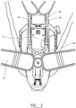
Figure 1 shows a rear view of a harness according to an embodiment of the invention, wherein the harness is in an extended position; -
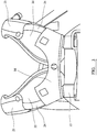
Figure 2 shows an inside view of a harness according to an embodiment of the invention, wherein the harness is in an extended position; -
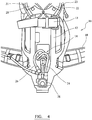
Figure 3 shows the shoulder straps according to an embodiment of the invention; and, -
Figure 4 shows a rear view of a harness according to an embodiment of the invention, wherein the harness is in an un-extended position. - Referring to
Figure 1 theharness 10 comprises aback plate 12, asliding plate 16, a pair ofshoulder straps belt 18. Thesliding plate 16 is slidably attached to theback plate 12 in such a way that it can move longitudinally with respect to the back plate between the extended position shown inFigure 1 and the un-extended position shown inFigure 4 . Theshoulder straps belt 18 is fixed to a lower portion of the back plate. Thesliding plate 16 can be fixed at various positions between the fully extended position and the un-extended position. This allows it to be comfortably worn by users of different heights. Avalve 28 is provided at the bottom of theback plate 12. In use a cylinder of breathable gas is connected to the valve and it is retained by theback plate 12 and aretaining strap 13. Two air supply hoses, or conduits, 24, 26 are connected to the valve for supplying breathable gas, one to the breathing apparatus of the harness wearer and one to a pressure gauge. Thehoses valve 28 and pass through anopening 14 in theback plate 12 to the inside of the back plate. In addition, or instead, one or more of the conduits may be an electrical cable. - Referring now to
Figure 2 , thehoses sliding plate 16, one being attached to each side. The hoses cross over in the region of theopening 14 and as such the side of thesliding plate 16 to which they are attached is different to the side of thevalve 28 from which they leave. There is a longitudinally extendingguide channel 34 for retaining the hoses on either side of thesliding plate 16. Theguide channels 34 are shaped with projections within and along their length so as to retain thehoses hoses sliding plate 16 and leave the sliding plate in the region of theshoulder straps - As can be seen in
Figure 3 , thehoses shoulder strap sleeves - When the
sliding plate 16 is moved to the non-extended position, shown inFigure 4 , thehoses back plate 12 and the positional mounting of thehoses sliding plate 16 the hoses fold within the region of theopening 14 of theback plate 12. Since the excess lengths of hose are accommodated within the confines of theback plate 12 there is no risk of snagging the hoses on obstacles. - To aid in the folding of the
hoses
Claims (13)
- A harness (10) for use with breathing apparatus, comprising:a back plate (12) for accommodating a gas cylinder;a sliding plate (16) adjustable in a longitudinal direction with respect to the back plate so as to enable the length of the harness to be varied;at least one shoulder strap (20, 22) attached to an upper portion of the sliding plate; andat least two flexible conduits (24, 26) extending from a lower portion of the back plate (12);wherein at least one of the flexible conduits (24, 26) extends along the sliding plate (16), to at least one predetermined position on the shoulder strap; and wherein retaining means are provided on the sliding plate to prevent longitudinal movement of the at least one flexible conduit with respect to the sliding plate, such that when the sliding plate is adjusted relative to the back plate the flexible conduit retains its predetermined position on the shoulder strap;characterised in that the at least
two flexible conduits (24, 26) cross one another in the lateral direction of the back plate, so as to assist the folding and unfolding of the conduits when the sliding plate (16) is moved. - A harness according to claim 1, wherein during adjustment of the sliding plate (16) relative to the back plate (12) the flexible conduits (24, 26) are arranged to fold or unfold within the confines of the back plate (12).
- A harness according to claim 1 or 2, wherein the harness comprises two shoulder straps (20, 22).
- A harness according to claim 3, wherein each strap has a flexible conduit (24, 26).
- A harness according to any preceding claim, wherein one or more guide channels (34) are provided on the sliding plate for accommodating one or more flexible conduits (24, 26).
- A harness according to claim 5, wherein the retaining means (30) are provided in the one or more guide channels (34).
- A harness according to claim 6, wherein the retaining means (30) comprises clamping elements provided in the one or more guide channels (34).
- A harness according to claim 5, wherein the guide channels (34) are shaped to provide the retaining means (30).
- A harness according to any preceding claim, wherein at least one of said conduits (24, 26) extends on one side of the back plate (12) from the lower portion of the back plate and passes through an opening (14) in the back plate to the other side of the back plate before extending along the sliding plate (16).
- A harness according to any preceding claim, wherein the back plate (12) has biasing means to help bias the folding and unfolding of the or each conduit (24, 26).
- A harness according to claim 10, wherein the biasing means includes one or more grooves or projections provided on the back plate (12).
- A harness according to any preceding claim, wherein the flexible conduits (24, 26) include a high-pressure hose (24) and a medium-pressure hose.
- A harness according to any preceding claim, wherein the flexible conduits (24, 26) include one or more electrical cables.
Applications Claiming Priority (1)
| Application Number | Priority Date | Filing Date | Title |
|---|---|---|---|
| GBGB0701861.7A GB0701861D0 (en) | 2007-01-31 | 2007-01-31 | Adjustable harness |
Publications (2)
| Publication Number | Publication Date |
|---|---|
| EP1952718A1 EP1952718A1 (en) | 2008-08-06 |
| EP1952718B1 true EP1952718B1 (en) | 2017-02-15 |
Family
ID=37891055
Family Applications (1)
| Application Number | Title | Priority Date | Filing Date |
|---|---|---|---|
| EP07124122.8A Active EP1952718B1 (en) | 2007-01-31 | 2007-12-28 | Adjustable harness |
Country Status (3)
| Country | Link |
|---|---|
| US (1) | US8205775B2 (en) |
| EP (1) | EP1952718B1 (en) |
| GB (1) | GB0701861D0 (en) |
Families Citing this family (6)
| Publication number | Priority date | Publication date | Assignee | Title |
|---|---|---|---|---|
| GB2470032B (en) * | 2009-05-06 | 2014-02-12 | Draeger Safety Uk Ltd | Improved harness for breathing apparatus |
| US9033616B2 (en) * | 2013-07-13 | 2015-05-19 | Sean Allen Krumhauer | Personal flotation device for a self contained breathing apparatus |
| KR102600882B1 (en) * | 2015-11-19 | 2023-11-09 | 허니웰 인터내셔널 인코포레이티드 | Quick coupling for harness and backrest of self-contained breathing apparatus |
| GB2572971A (en) * | 2018-04-17 | 2019-10-23 | Draeger Safety Uk Ltd | Adjustable harness |
| JP6755278B2 (en) * | 2018-05-30 | 2020-09-16 | エア・ウォーター防災株式会社 | Backpack and respirator |
| GB2614883A (en) * | 2022-01-19 | 2023-07-26 | Draeger Safety Ag & Co Kgaa | Modular support system |
Citations (1)
| Publication number | Priority date | Publication date | Assignee | Title |
|---|---|---|---|---|
| WO2001097917A1 (en) * | 2000-06-19 | 2001-12-27 | Msa Auer Gmbh | Support frame for a respiratory air container |
Family Cites Families (9)
| Publication number | Priority date | Publication date | Assignee | Title |
|---|---|---|---|---|
| US1448918A (en) * | 1921-06-09 | 1923-03-20 | Drager Alexander Bernhard | Supporting frame for self-contained breathing apparatus |
| US2362643A (en) * | 1942-01-21 | 1944-11-14 | Christian J Lambertsen | Breathing apparatus for use under water |
| US2764151A (en) * | 1953-06-16 | 1956-09-25 | Scott Aviation Corp | Underwater breathing apparatus |
| BE529262A (en) * | 1954-05-31 | 1954-11-30 | ||
| US5022790A (en) * | 1989-12-04 | 1991-06-11 | Rolyn Productions Inc. | Audible signalling system for divers |
| JP2558028B2 (en) * | 1991-10-23 | 1996-11-27 | 株式会社タバタ | Buoyancy regulator for diving |
| US5584289A (en) * | 1995-06-07 | 1996-12-17 | Mine Safety Appliances Company | Breathing apparatus having a flexible manifold connected between a plurality of air cylinders |
| US6478510B1 (en) * | 2001-04-23 | 2002-11-12 | Adam E. Young | Dive vest |
| GB2383397B (en) * | 2001-12-20 | 2005-10-12 | Internat Safety Instr Inc | Breathing apparatus |
-
2007
- 2007-01-31 GB GBGB0701861.7A patent/GB0701861D0/en not_active Ceased
- 2007-12-28 EP EP07124122.8A patent/EP1952718B1/en active Active
-
2008
- 2008-01-09 US US11/971,635 patent/US8205775B2/en active Active
Patent Citations (1)
| Publication number | Priority date | Publication date | Assignee | Title |
|---|---|---|---|---|
| WO2001097917A1 (en) * | 2000-06-19 | 2001-12-27 | Msa Auer Gmbh | Support frame for a respiratory air container |
Also Published As
| Publication number | Publication date |
|---|---|
| US8205775B2 (en) | 2012-06-26 |
| US20080179366A1 (en) | 2008-07-31 |
| GB0701861D0 (en) | 2007-03-14 |
| EP1952718A1 (en) | 2008-08-06 |
Similar Documents
| Publication | Publication Date | Title |
|---|---|---|
| EP2248557B1 (en) | Improved harness for breathing apparatus | |
| US8622268B2 (en) | Structural support member for a harness for breathing apparatus | |
| EP1952718A1 (en) | Adjustable harness | |
| EP3318306B1 (en) | Leg strap assembly and safety harness including the same | |
| AU2001262035B2 (en) | Support frame for a respiratory air container | |
| EP2248555B1 (en) | Gas-cylinder retaining assembly | |
| US10092783B2 (en) | Operating handle for an avalanche rescue system, functional unit of an avalanche rescue system and avalanche rescue system | |
| CN101879359B (en) | Harness for breathing apparatus | |
| EP2686073B1 (en) | Harness for breathing apparatus | |
| NZ527288A (en) | Safety harness | |
| US10994159B2 (en) | Harness for breathing apparatus | |
| EP2248554B1 (en) | Two-part structural support member for a harness for breathing apparatus | |
| GB2606676A (en) | Adjustable harness | |
| EP2686074A2 (en) | Harness for breathing apparatus | |
| EP2248556A1 (en) | Clip for use with breathing apparatus | |
| JP7644495B2 (en) | Full harness type fall arrest device | |
| GB2572971A (en) | Adjustable harness | |
| KR20200001588U (en) | Safety belt | |
| ITMO20130278A1 (en) | SAFETY BELT FOR THE HOLDING OF OPERATORS ON BOARD VEHICLES, INTEGRATING JACKET OF THE ABOVE BELT AND ASSOCIATED SEAT-SEAT ASSEMBLY | |
| ITMI20011862A1 (en) | SUPPORT FOR EARPHONE GROUP FOR MASK FOR DIVING |
Legal Events
| Date | Code | Title | Description |
|---|---|---|---|
| PUAI | Public reference made under article 153(3) epc to a published international application that has entered the european phase |
Free format text: ORIGINAL CODE: 0009012 |
|
| AK | Designated contracting states |
Kind code of ref document: A1 Designated state(s): AT BE BG CH CY CZ DE DK EE ES FI FR GB GR HU IE IS IT LI LT LU LV MC MT NL PL PT RO SE SI SK TR |
|
| AX | Request for extension of the european patent |
Extension state: AL BA HR MK RS |
|
| 17P | Request for examination filed |
Effective date: 20090204 |
|
| 17Q | First examination report despatched |
Effective date: 20090307 |
|
| AKX | Designation fees paid |
Designated state(s): AT BE BG CH CY CZ DE DK EE ES FI FR GB GR HU IE IS IT LI LT LU LV MC MT NL PL PT RO SE SI SK TR |
|
| R17C | First examination report despatched (corrected) |
Effective date: 20090317 |
|
| REG | Reference to a national code |
Ref country code: DE Ref legal event code: R079 Ref document number: 602007049802 Country of ref document: DE Free format text: PREVIOUS MAIN CLASS: A45F0003100000 Ipc: A62B0009040000 |
|
| GRAP | Despatch of communication of intention to grant a patent |
Free format text: ORIGINAL CODE: EPIDOSNIGR1 |
|
| RIC1 | Information provided on ipc code assigned before grant |
Ipc: A62B 25/00 20060101ALI20160129BHEP Ipc: A62B 9/04 20060101AFI20160129BHEP Ipc: B63C 11/22 20060101ALI20160129BHEP |
|
| INTG | Intention to grant announced |
Effective date: 20160224 |
|
| GRAJ | Information related to disapproval of communication of intention to grant by the applicant or resumption of examination proceedings by the epo deleted |
Free format text: ORIGINAL CODE: EPIDOSDIGR1 |
|
| GRAP | Despatch of communication of intention to grant a patent |
Free format text: ORIGINAL CODE: EPIDOSNIGR1 |
|
| INTC | Intention to grant announced (deleted) | ||
| INTG | Intention to grant announced |
Effective date: 20160726 |
|
| GRAS | Grant fee paid |
Free format text: ORIGINAL CODE: EPIDOSNIGR3 |
|
| GRAA | (expected) grant |
Free format text: ORIGINAL CODE: 0009210 |
|
| AK | Designated contracting states |
Kind code of ref document: B1 Designated state(s): AT BE BG CH CY CZ DE DK EE ES FI FR GB GR HU IE IS IT LI LT LU LV MC MT NL PL PT RO SE SI SK TR |
|
| REG | Reference to a national code |
Ref country code: CH Ref legal event code: EP Ref country code: GB Ref legal event code: FG4D |
|
| REG | Reference to a national code |
Ref country code: IE Ref legal event code: FG4D |
|
| REG | Reference to a national code |
Ref country code: AT Ref legal event code: REF Ref document number: 867578 Country of ref document: AT Kind code of ref document: T Effective date: 20170315 |
|
| REG | Reference to a national code |
Ref country code: DE Ref legal event code: R096 Ref document number: 602007049802 Country of ref document: DE |
|
| REG | Reference to a national code |
Ref country code: NL Ref legal event code: MP Effective date: 20170215 |
|
| REG | Reference to a national code |
Ref country code: LT Ref legal event code: MG4D |
|
| REG | Reference to a national code |
Ref country code: NL Ref legal event code: NE Effective date: 20170710 |
|
| REG | Reference to a national code |
Ref country code: AT Ref legal event code: MK05 Ref document number: 867578 Country of ref document: AT Kind code of ref document: T Effective date: 20170215 |
|
| PG25 | Lapsed in a contracting state [announced via postgrant information from national office to epo] |
Ref country code: GR Free format text: LAPSE BECAUSE OF FAILURE TO SUBMIT A TRANSLATION OF THE DESCRIPTION OR TO PAY THE FEE WITHIN THE PRESCRIBED TIME-LIMIT Effective date: 20170516 Ref country code: FI Free format text: LAPSE BECAUSE OF FAILURE TO SUBMIT A TRANSLATION OF THE DESCRIPTION OR TO PAY THE FEE WITHIN THE PRESCRIBED TIME-LIMIT Effective date: 20170215 Ref country code: LT Free format text: LAPSE BECAUSE OF FAILURE TO SUBMIT A TRANSLATION OF THE DESCRIPTION OR TO PAY THE FEE WITHIN THE PRESCRIBED TIME-LIMIT Effective date: 20170215 |
|
| PG25 | Lapsed in a contracting state [announced via postgrant information from national office to epo] |
Ref country code: ES Free format text: LAPSE BECAUSE OF FAILURE TO SUBMIT A TRANSLATION OF THE DESCRIPTION OR TO PAY THE FEE WITHIN THE PRESCRIBED TIME-LIMIT Effective date: 20170215 Ref country code: SE Free format text: LAPSE BECAUSE OF FAILURE TO SUBMIT A TRANSLATION OF THE DESCRIPTION OR TO PAY THE FEE WITHIN THE PRESCRIBED TIME-LIMIT Effective date: 20170215 Ref country code: PT Free format text: LAPSE BECAUSE OF FAILURE TO SUBMIT A TRANSLATION OF THE DESCRIPTION OR TO PAY THE FEE WITHIN THE PRESCRIBED TIME-LIMIT Effective date: 20170615 Ref country code: BG Free format text: LAPSE BECAUSE OF FAILURE TO SUBMIT A TRANSLATION OF THE DESCRIPTION OR TO PAY THE FEE WITHIN THE PRESCRIBED TIME-LIMIT Effective date: 20170515 Ref country code: LV Free format text: LAPSE BECAUSE OF FAILURE TO SUBMIT A TRANSLATION OF THE DESCRIPTION OR TO PAY THE FEE WITHIN THE PRESCRIBED TIME-LIMIT Effective date: 20170215 Ref country code: NL Free format text: LAPSE BECAUSE OF FAILURE TO SUBMIT A TRANSLATION OF THE DESCRIPTION OR TO PAY THE FEE WITHIN THE PRESCRIBED TIME-LIMIT Effective date: 20170215 Ref country code: AT Free format text: LAPSE BECAUSE OF FAILURE TO SUBMIT A TRANSLATION OF THE DESCRIPTION OR TO PAY THE FEE WITHIN THE PRESCRIBED TIME-LIMIT Effective date: 20170215 |
|
| PG25 | Lapsed in a contracting state [announced via postgrant information from national office to epo] |
Ref country code: EE Free format text: LAPSE BECAUSE OF FAILURE TO SUBMIT A TRANSLATION OF THE DESCRIPTION OR TO PAY THE FEE WITHIN THE PRESCRIBED TIME-LIMIT Effective date: 20170215 Ref country code: RO Free format text: LAPSE BECAUSE OF FAILURE TO SUBMIT A TRANSLATION OF THE DESCRIPTION OR TO PAY THE FEE WITHIN THE PRESCRIBED TIME-LIMIT Effective date: 20170215 Ref country code: CZ Free format text: LAPSE BECAUSE OF FAILURE TO SUBMIT A TRANSLATION OF THE DESCRIPTION OR TO PAY THE FEE WITHIN THE PRESCRIBED TIME-LIMIT Effective date: 20170215 Ref country code: SK Free format text: LAPSE BECAUSE OF FAILURE TO SUBMIT A TRANSLATION OF THE DESCRIPTION OR TO PAY THE FEE WITHIN THE PRESCRIBED TIME-LIMIT Effective date: 20170215 Ref country code: IT Free format text: LAPSE BECAUSE OF FAILURE TO SUBMIT A TRANSLATION OF THE DESCRIPTION OR TO PAY THE FEE WITHIN THE PRESCRIBED TIME-LIMIT Effective date: 20170215 |
|
| REG | Reference to a national code |
Ref country code: DE Ref legal event code: R097 Ref document number: 602007049802 Country of ref document: DE |
|
| PG25 | Lapsed in a contracting state [announced via postgrant information from national office to epo] |
Ref country code: PL Free format text: LAPSE BECAUSE OF FAILURE TO SUBMIT A TRANSLATION OF THE DESCRIPTION OR TO PAY THE FEE WITHIN THE PRESCRIBED TIME-LIMIT Effective date: 20170215 Ref country code: DK Free format text: LAPSE BECAUSE OF FAILURE TO SUBMIT A TRANSLATION OF THE DESCRIPTION OR TO PAY THE FEE WITHIN THE PRESCRIBED TIME-LIMIT Effective date: 20170215 |
|
| REG | Reference to a national code |
Ref country code: FR Ref legal event code: PLFP Year of fee payment: 11 |
|
| PLBE | No opposition filed within time limit |
Free format text: ORIGINAL CODE: 0009261 |
|
| STAA | Information on the status of an ep patent application or granted ep patent |
Free format text: STATUS: NO OPPOSITION FILED WITHIN TIME LIMIT |
|
| 26N | No opposition filed |
Effective date: 20171116 |
|
| PG25 | Lapsed in a contracting state [announced via postgrant information from national office to epo] |
Ref country code: SI Free format text: LAPSE BECAUSE OF FAILURE TO SUBMIT A TRANSLATION OF THE DESCRIPTION OR TO PAY THE FEE WITHIN THE PRESCRIBED TIME-LIMIT Effective date: 20170215 |
|
| REG | Reference to a national code |
Ref country code: CH Ref legal event code: PL |
|
| REG | Reference to a national code |
Ref country code: IE Ref legal event code: MM4A |
|
| PG25 | Lapsed in a contracting state [announced via postgrant information from national office to epo] |
Ref country code: LU Free format text: LAPSE BECAUSE OF NON-PAYMENT OF DUE FEES Effective date: 20171228 Ref country code: MT Free format text: LAPSE BECAUSE OF NON-PAYMENT OF DUE FEES Effective date: 20171228 |
|
| REG | Reference to a national code |
Ref country code: BE Ref legal event code: MM Effective date: 20171231 |
|
| PG25 | Lapsed in a contracting state [announced via postgrant information from national office to epo] |
Ref country code: IE Free format text: LAPSE BECAUSE OF NON-PAYMENT OF DUE FEES Effective date: 20171228 |
|
| PG25 | Lapsed in a contracting state [announced via postgrant information from national office to epo] |
Ref country code: LI Free format text: LAPSE BECAUSE OF NON-PAYMENT OF DUE FEES Effective date: 20171231 Ref country code: BE Free format text: LAPSE BECAUSE OF NON-PAYMENT OF DUE FEES Effective date: 20171231 Ref country code: CH Free format text: LAPSE BECAUSE OF NON-PAYMENT OF DUE FEES Effective date: 20171231 |
|
| PG25 | Lapsed in a contracting state [announced via postgrant information from national office to epo] |
Ref country code: MC Free format text: LAPSE BECAUSE OF FAILURE TO SUBMIT A TRANSLATION OF THE DESCRIPTION OR TO PAY THE FEE WITHIN THE PRESCRIBED TIME-LIMIT Effective date: 20170215 Ref country code: HU Free format text: LAPSE BECAUSE OF FAILURE TO SUBMIT A TRANSLATION OF THE DESCRIPTION OR TO PAY THE FEE WITHIN THE PRESCRIBED TIME-LIMIT; INVALID AB INITIO Effective date: 20071228 |
|
| PG25 | Lapsed in a contracting state [announced via postgrant information from national office to epo] |
Ref country code: CY Free format text: LAPSE BECAUSE OF NON-PAYMENT OF DUE FEES Effective date: 20170215 |
|
| PG25 | Lapsed in a contracting state [announced via postgrant information from national office to epo] |
Ref country code: TR Free format text: LAPSE BECAUSE OF FAILURE TO SUBMIT A TRANSLATION OF THE DESCRIPTION OR TO PAY THE FEE WITHIN THE PRESCRIBED TIME-LIMIT Effective date: 20170215 |
|
| PG25 | Lapsed in a contracting state [announced via postgrant information from national office to epo] |
Ref country code: IS Free format text: LAPSE BECAUSE OF FAILURE TO SUBMIT A TRANSLATION OF THE DESCRIPTION OR TO PAY THE FEE WITHIN THE PRESCRIBED TIME-LIMIT Effective date: 20170615 |
|
| REG | Reference to a national code |
Ref country code: DE Ref legal event code: R082 Ref document number: 602007049802 Country of ref document: DE Representative=s name: HL KEMPNER PATENTANWAELTE, SOLICITORS (ENGLAND, DE Ref country code: DE Ref legal event code: R082 Ref document number: 602007049802 Country of ref document: DE Representative=s name: HL KEMPNER PATENTANWALT, RECHTSANWALT, SOLICIT, DE Ref country code: DE Ref legal event code: R082 Ref document number: 602007049802 Country of ref document: DE Representative=s name: HL KEMPNER PARTG MBB, DE |
|
| PGFP | Annual fee paid to national office [announced via postgrant information from national office to epo] |
Ref country code: DE Payment date: 20251215 Year of fee payment: 19 |
|
| PGFP | Annual fee paid to national office [announced via postgrant information from national office to epo] |
Ref country code: GB Payment date: 20251216 Year of fee payment: 19 |
|
| PGFP | Annual fee paid to national office [announced via postgrant information from national office to epo] |
Ref country code: FR Payment date: 20251120 Year of fee payment: 19 |