EP1950980B1 - Autostereoscopic 2D/3D switchable display apparatus with high light efficiency, employing a lenticular screen and time-multiplexing of 3D-views - Google Patents
Autostereoscopic 2D/3D switchable display apparatus with high light efficiency, employing a lenticular screen and time-multiplexing of 3D-views Download PDFInfo
- Publication number
- EP1950980B1 EP1950980B1 EP07122930.6A EP07122930A EP1950980B1 EP 1950980 B1 EP1950980 B1 EP 1950980B1 EP 07122930 A EP07122930 A EP 07122930A EP 1950980 B1 EP1950980 B1 EP 1950980B1
- Authority
- EP
- European Patent Office
- Prior art keywords
- polarization
- light
- birefringent element
- birefringent
- display apparatus
- Prior art date
- Legal status (The legal status is an assumption and is not a legal conclusion. Google has not performed a legal analysis and makes no representation as to the accuracy of the status listed.)
- Not-in-force
Links
Images


Classifications
-
- H—ELECTRICITY
- H04—ELECTRIC COMMUNICATION TECHNIQUE
- H04N—PICTORIAL COMMUNICATION, e.g. TELEVISION
- H04N13/00—Stereoscopic video systems; Multi-view video systems; Details thereof
- H04N13/30—Image reproducers
- H04N13/302—Image reproducers for viewing without the aid of special glasses, i.e. using autostereoscopic displays
- H04N13/305—Image reproducers for viewing without the aid of special glasses, i.e. using autostereoscopic displays using lenticular lenses, e.g. arrangements of cylindrical lenses
-
- G—PHYSICS
- G02—OPTICS
- G02B—OPTICAL ELEMENTS, SYSTEMS OR APPARATUS
- G02B30/00—Optical systems or apparatus for producing three-dimensional [3D] effects, e.g. stereoscopic images
- G02B30/20—Optical systems or apparatus for producing three-dimensional [3D] effects, e.g. stereoscopic images by providing first and second parallax images to an observer's left and right eyes
- G02B30/22—Optical systems or apparatus for producing three-dimensional [3D] effects, e.g. stereoscopic images by providing first and second parallax images to an observer's left and right eyes of the stereoscopic type
- G02B30/24—Optical systems or apparatus for producing three-dimensional [3D] effects, e.g. stereoscopic images by providing first and second parallax images to an observer's left and right eyes of the stereoscopic type involving temporal multiplexing, e.g. using sequentially activated left and right shutters
-
- G—PHYSICS
- G02—OPTICS
- G02B—OPTICAL ELEMENTS, SYSTEMS OR APPARATUS
- G02B30/00—Optical systems or apparatus for producing three-dimensional [3D] effects, e.g. stereoscopic images
- G02B30/20—Optical systems or apparatus for producing three-dimensional [3D] effects, e.g. stereoscopic images by providing first and second parallax images to an observer's left and right eyes
- G02B30/22—Optical systems or apparatus for producing three-dimensional [3D] effects, e.g. stereoscopic images by providing first and second parallax images to an observer's left and right eyes of the stereoscopic type
- G02B30/25—Optical systems or apparatus for producing three-dimensional [3D] effects, e.g. stereoscopic images by providing first and second parallax images to an observer's left and right eyes of the stereoscopic type using polarisation techniques
-
- G—PHYSICS
- G02—OPTICS
- G02F—OPTICAL DEVICES OR ARRANGEMENTS FOR THE CONTROL OF LIGHT BY MODIFICATION OF THE OPTICAL PROPERTIES OF THE MEDIA OF THE ELEMENTS INVOLVED THEREIN; NON-LINEAR OPTICS; FREQUENCY-CHANGING OF LIGHT; OPTICAL LOGIC ELEMENTS; OPTICAL ANALOGUE/DIGITAL CONVERTERS
- G02F1/00—Devices or arrangements for the control of the intensity, colour, phase, polarisation or direction of light arriving from an independent light source, e.g. switching, gating or modulating; Non-linear optics
- G02F1/01—Devices or arrangements for the control of the intensity, colour, phase, polarisation or direction of light arriving from an independent light source, e.g. switching, gating or modulating; Non-linear optics for the control of the intensity, phase, polarisation or colour
- G02F1/13—Devices or arrangements for the control of the intensity, colour, phase, polarisation or direction of light arriving from an independent light source, e.g. switching, gating or modulating; Non-linear optics for the control of the intensity, phase, polarisation or colour based on liquid crystals, e.g. single liquid crystal display cells
- G02F1/133—Constructional arrangements; Operation of liquid crystal cells; Circuit arrangements
- G02F1/1333—Constructional arrangements; Manufacturing methods
- G02F1/1335—Structural association of cells with optical devices, e.g. polarisers or reflectors
-
- H—ELECTRICITY
- H04—ELECTRIC COMMUNICATION TECHNIQUE
- H04N—PICTORIAL COMMUNICATION, e.g. TELEVISION
- H04N13/00—Stereoscopic video systems; Multi-view video systems; Details thereof
- H04N13/30—Image reproducers
- H04N13/302—Image reproducers for viewing without the aid of special glasses, i.e. using autostereoscopic displays
- H04N13/31—Image reproducers for viewing without the aid of special glasses, i.e. using autostereoscopic displays using parallax barriers
- H04N13/312—Image reproducers for viewing without the aid of special glasses, i.e. using autostereoscopic displays using parallax barriers the parallax barriers being placed behind the display panel, e.g. between backlight and spatial light modulator [SLM]
-
- H—ELECTRICITY
- H04—ELECTRIC COMMUNICATION TECHNIQUE
- H04N—PICTORIAL COMMUNICATION, e.g. TELEVISION
- H04N13/00—Stereoscopic video systems; Multi-view video systems; Details thereof
- H04N13/30—Image reproducers
- H04N13/302—Image reproducers for viewing without the aid of special glasses, i.e. using autostereoscopic displays
- H04N13/31—Image reproducers for viewing without the aid of special glasses, i.e. using autostereoscopic displays using parallax barriers
- H04N13/315—Image reproducers for viewing without the aid of special glasses, i.e. using autostereoscopic displays using parallax barriers the parallax barriers being time-variant
-
- H—ELECTRICITY
- H04—ELECTRIC COMMUNICATION TECHNIQUE
- H04N—PICTORIAL COMMUNICATION, e.g. TELEVISION
- H04N13/00—Stereoscopic video systems; Multi-view video systems; Details thereof
- H04N13/30—Image reproducers
- H04N13/302—Image reproducers for viewing without the aid of special glasses, i.e. using autostereoscopic displays
- H04N13/32—Image reproducers for viewing without the aid of special glasses, i.e. using autostereoscopic displays using arrays of controllable light sources; using moving apertures or moving light sources
-
- H—ELECTRICITY
- H04—ELECTRIC COMMUNICATION TECHNIQUE
- H04N—PICTORIAL COMMUNICATION, e.g. TELEVISION
- H04N13/00—Stereoscopic video systems; Multi-view video systems; Details thereof
- H04N13/30—Image reproducers
- H04N13/349—Multi-view displays for displaying three or more geometrical viewpoints without viewer tracking
- H04N13/354—Multi-view displays for displaying three or more geometrical viewpoints without viewer tracking for displaying sequentially
-
- H—ELECTRICITY
- H04—ELECTRIC COMMUNICATION TECHNIQUE
- H04N—PICTORIAL COMMUNICATION, e.g. TELEVISION
- H04N13/00—Stereoscopic video systems; Multi-view video systems; Details thereof
- H04N13/30—Image reproducers
- H04N13/356—Image reproducers having separate monoscopic and stereoscopic modes
- H04N13/359—Switching between monoscopic and stereoscopic modes
-
- G—PHYSICS
- G02—OPTICS
- G02B—OPTICAL ELEMENTS, SYSTEMS OR APPARATUS
- G02B27/00—Optical systems or apparatus not provided for by any of the groups G02B1/00 - G02B26/00, G02B30/00
- G02B27/28—Optical systems or apparatus not provided for by any of the groups G02B1/00 - G02B26/00, G02B30/00 for polarising
- G02B27/286—Optical systems or apparatus not provided for by any of the groups G02B1/00 - G02B26/00, G02B30/00 for polarising for controlling or changing the state of polarisation, e.g. transforming one polarisation state into another
-
- G—PHYSICS
- G09—EDUCATION; CRYPTOGRAPHY; DISPLAY; ADVERTISING; SEALS
- G09G—ARRANGEMENTS OR CIRCUITS FOR CONTROL OF INDICATING DEVICES USING STATIC MEANS TO PRESENT VARIABLE INFORMATION
- G09G2300/00—Aspects of the constitution of display devices
- G09G2300/02—Composition of display devices
- G09G2300/023—Display panel composed of stacked panels
-
- G—PHYSICS
- G09—EDUCATION; CRYPTOGRAPHY; DISPLAY; ADVERTISING; SEALS
- G09G—ARRANGEMENTS OR CIRCUITS FOR CONTROL OF INDICATING DEVICES USING STATIC MEANS TO PRESENT VARIABLE INFORMATION
- G09G3/00—Control arrangements or circuits, of interest only in connection with visual indicators other than cathode-ray tubes
- G09G3/001—Control arrangements or circuits, of interest only in connection with visual indicators other than cathode-ray tubes using specific devices not provided for in groups G09G3/02 - G09G3/36, e.g. using an intermediate record carrier such as a film slide; Projection systems; Display of non-alphanumerical information, solely or in combination with alphanumerical information, e.g. digital display on projected diapositive as background
- G09G3/003—Control arrangements or circuits, of interest only in connection with visual indicators other than cathode-ray tubes using specific devices not provided for in groups G09G3/02 - G09G3/36, e.g. using an intermediate record carrier such as a film slide; Projection systems; Display of non-alphanumerical information, solely or in combination with alphanumerical information, e.g. digital display on projected diapositive as background to produce spatial visual effects
Definitions
- the present invention relates to a 2D/3D switchable display apparatus, and more particularly, to a highly efficient 2D/3D switchable display apparatus having improved brightness by enhancing a light use efficiency.
- a stereo image display providing a stereo image is greatly needed in a variety of fields such as medical images, games, advertisements, education, and military affairs. Also, as high resolution TVs are becoming popular, stereo TVs that can display stereo images are expected to be popular in the future.
- a stereo image display apparatus provides an image for the left eye and an image for the right eye having a binocular parallax respectively to the left eye and the right eye of a user.
- the user recognizes the left eye image and the right eye image provided by the stereo image display apparatus through the retinas of both eyes so as to view a 3D stereo image.
- the stereo image display apparatus includes a parallax barrier type and a lenticular type.
- a stereo image display apparatus of the parallax barrier type includes a backlight unit 11, an LCD panel 13, and a parallax barrier 12 having an opening 12a and a barrier 12b which are arranged at a predetermined period.
- the parallax barrier 12 is arranged between the LCD panel 13 and the backlight unit 11, the parallax barrier 12 can be arranged in front of the LCD panel 13.
- the images for the left and right eyes alternately displayed by the LCD panel 13 can be separated by the opening 12a of the parallax barrier 12.
- a stereo image display needs a switching operation between a 2D image mode and a 3D image mode.
- a method has been suggested in which a reflection film 14 is coated on the surface of the barrier 12b facing the backlight unit 11 and a reflection panel 15 is installed on the lower surface of the backlight unit 11.
- the light emitted from the backlight unit 11 and incident on the barrier 12b can be reused because the light is reflected by the reflection film 14 and then reflected again by the reflection panel 15.
- EP-A-1742492 discloses a 2D/3D switchable autostereoscopic display apparatus having a backlight unit, a polarization switch, a birefringent element array, a lens array, and a display panel with a polarizer on each face.
- the present invention provides a 2D/3D switchable display apparatus which can improve brightness by enhancing a light use efficiency and realize a high resolution.
- the present invention provides an image display apparatus for a 2D/3D switchable display including a backlight unit where a reflection panel is installed at a back thereof, a polarization panel for transmitting only light of a particular polarization direction of light emitted from the backlight unit, a polarization switch operable for changing the polarization direction of incident light, a birefringent element array formed from an alternately arranged plurality of first and second birefringent elements for changing the polarization direction of incident light to make the polarization directions of light passing through the first and second birefringent elements perpendicular to each other, a reflective polarizer for transmitting only light of a particular polarization direction of the light passing through the birefringent element array and reflecting light of the other polarization direction, a lens array separating light transmitted by the reflection polarizer and incident from a first birefringent element into a first view zone and from a second birefringent element into a second view zone, and a display panel
- the polarization switch may be switched among first through third states in which the polarization direction of incident light is changed differently.
- the polarization switch may be switched among a first state in which the polarization direction of incident light is not changed, a second state in which the polarization direction of incident light is changed by 45°, and a third state in which the polarization direction of incident light is changed by 90°.
- the birefringent element array may be formed by alternately arranging in a horizontal direction the first and second birefringent elements that are vertical.
- Each of the first and second birefringent elements may be formed of a retarder that delays incident light by a predetermined phase and a phase delay difference between a retarder forming the first birefringent element and a retarder forming the second birefringent element is ⁇ /2.
- Each of the first and second birefringent elements may be formed of a rotator that rotates incident light by a predetermined angle and a rotation angle difference between a rotator forming the first birefringent element and a rotator forming the second birefringent element is 90°.
- the lens array may be formed by arranging a plurality of lenticular lens elements that are vertical and parallel to birefringent elements of the birefringent element array in a horizontal direction.
- the reflective polarizer may be a wire-grid polarizer formed of metal wires arranged parallel to one another at a constant interval.
- the polarization panel transmits only light of a particular polarization direction of the light emitted from the backlight unit and reflects light of the other polarization direction.
- the polarization switch is divided into a plurality of horizontal segments that are sequentially switched in synchronism with a vertical scanning time of the display panel.
- an image display apparatus including a backlight unit where a reflection panel is installed at a back thereof, a polarization panel transmitting only light of a particular polarization direction of light emitted from the backlight unit, a polarization switch changing the polarization direction of incident light, a reflective polarizer array formed by alternately arranging a first reflective polarizer that reflects first polarization light and transmits second polarization light and a second reflective polarizer that transmits the first polarization light and reflects the second polarization light, a birefringent element array formed by alternately arranging a plurality of first and second birefringent elements and changing the polarization direction of incident light to make the polarization directions of light passing through the first and second birefringent elements perpendicular to each other, a lens array separating incident light into a first view zone and a second view zone, and a display panel displaying an image.
- the polarization switch may be switched among first through third states in which the polarization direction of incident light is changed differently.
- the polarization switch may be switched among a first state in which the polarization direction of incident light is not changed, a second state in which the polarization direction of incident light is changed by 45°, and a third state in which the polarization direction of incident light is changed by 90°.
- the birefringent element array may be formed by alternately arranging in a horizontal direction the first and second birefringent elements that are vertical.
- Each of the first and second birefringent elements may be formed of a retarder that delays incident light by a predetermined phase and a phase delay difference between a retarder forming the first birefringent element and a retarder forming the second birefringent element is ⁇ /2.
- Each of the first and second birefringent elements may be formed of a rotator that rotates incident light by a predetermined angle and a rotation angle difference between a rotator forming the first birefringent element and a rotator forming the second birefringent element is 90°.
- the lens array may be formed by arranging a plurality of lenticular lens elements that are vertical and parallel to birefringent elements of the birefringent element array in a horizontal direction.
- the first and second reflective polarizers of the reflective polarizer array may be respectively arranged to face the first and second birefringent elements of the birefringent element array.
- the first and second reflective polarizers may be wire-grid polarizers formed of metal wires arranged parallel to one another at a constant interval, and the metal wire of the first reflective polarizer and the metal wire of the second reflective polarizer may be arranged perpendicular to each other.
- the polarization panel may transmit only light of a particular polarization direction of the light emitted from the backlight unit and reflects light of the other polarization direction of the light emitted from the backlight unit.
- the polarization switch may be divided into a plurality of horizontal segments that are sequentially switched in synchronism with a vertical scanning time of the display panel.
- FIGS. 3A and 3B schematically illustrate the structure and operation of a stereo image display apparatus having an improved light use efficiency according to an exemplary embodiment of the present invention.
- an image display apparatus 20 includes a backlight unit 21 having a reflection panel 28 installed at a bottom surface thereof, a polarization panel 22 transmitting light only in a particular polarization direction of the light emitted from the backlight unit 21, a polarization switch 23 converting the polarization direction of the incident light according to electric control, a birefringent element array 24 having a plurality of first and second birefringent elements 24a and 24b converting the polarization direction of the incident light which are alternately formed, a reflective polarizer 25 transmitting only light of a particular polarization direction of the light passing through the birefringent element array 24 and reflecting light of the other polarization direction, a lens array 26 separating the incident light into a left eye view zone and a right eye view zone, and
- the polarization panel 22 may be a general absorptive polarizer that transmits light of a particular polarization direction and absorbs the other light of the light emitted from the backlight unit 21.
- a reflective polarization film having a multilayer structure such as a dual brightness enhancement film (DBEF) which transmits the light of a particular polarization direction and reflects the others may be used as the polarization panel 22.
- DBEF dual brightness enhancement film
- the display panel 27 is a non-emissive display such as an LCD panel using the backlight unit 21 as a light source.
- the display panel 27 according to the present invention alternately displays a right eye image and a left eye image in a 3D mode according to the passage of time.
- the display panel 27 operates such that the right eye image is displayed at a first frame and the left eye image is displayed at a second frame.
- a high response speed LCD having a refresh rate of 120 Hz or higher may be used as the display panel 27.
- the polarization switch 23 may switch between first through third states respectively having a difference of 45° in the polarization direction of light passing through the polarization switch 23.
- the polarization switch 23 has a first state in which the polarization direction of the incident light is not changed, a second state in which the polarization direction of the incident light is changed by 45°, and a third state in which the polarization direction of the incident light is changed by 90°.
- the change angle of the polarization direction is exemplary and the polarization switch 23 can be designed to be different according to the polarization characteristic of the polarization panel 22 and the birefringent element array 24.
- the polarization switch 23 is formed of an electrically controllable device having three anisotropic statuses according to the amount of an applied voltage.
- a liquid crystal retarder can be used as the polarization switch 23.
- the polarization switch 23 is the liquid crystal retarder, for example, the incident light is not delayed in the first state, the phase of the incident light is delayed by 1/4 wavelength ( ⁇ /4) in the second state, and the phase of the incident light is delayed by 1/2 wavelength ( ⁇ /2) in the third state.
- the birefringent element array 24 has the first and second birefringent elements 24a and 24b which are alternately formed in the horizontal direction.
- the first and second birefringent elements 24a and 24b are respectively formed in the vertical direction of the image display apparatus 20 and arranged alternately in the horizontal direction.
- the birefringent element array 24 changes the polarization direction of the incident light such that the polarization directions of the light passing through the first and second birefringent elements 24a and 24b are perpendicular to each other.
- the first and second birefringent elements 24a and 24b can be formed of retarders that delay the incident light by a predetermined phase.
- the retarder forming the first birefringent element 24a and the retarder forming the second birefringent element 24b are configured to have a phase delay difference of ⁇ /2.
- the first birefringent element 24a does not delay phase while the second birefringent element 24b delays phase by ⁇ /2.
- the first birefringent 24a delays the phase by - ⁇ /4 while the second birefringent element 24b delays phase by + ⁇ /4.
- the first and second birefringent elements 24a and 24b can be formed of rotators rotating the incident light at a predetermined angle.
- a rotator forming the first birefringent element 24a and a rotator forming the second birefringent element 24b are configured to have a rotation angle difference of 90.
- the first birefringent element 24a does not rotate the incident light while the second birefringent element 24b rotates the incident light by 90°.
- the first birefringent element 24a rotates the incident light by -45° while the second birefringent element 24b rotates the incident light by +45°.
- the reflective polarizer 25 transmits only light of a particular polarization direction and reflects light of a different polarization direction of the light passing through the birefringent element array 24.
- the reflective polarizer 25 transmits light of the same polarization direction as that of a rear polarizer (not shown) arranged at the rear surface of the LCD panel and reflects light of a polarization direction perpendicular to the polarization direction of the rear polarizer.
- the rear polarizer of the LCD panel can be replaced by the reflective polarizer 25.
- the polarization extinction ratio of the reflective polarizer 25 may be very high.
- a wire-grid polarizer for example, can be used as the reflective polarizer 25.
- the wire-grid polarizer is formed by arranging a plurality of thin conductive metal wires 25b on a transparent substrate 25a in parallel at a predetermined interval.
- the wire-grid polarizer has more of a characteristic as a diffraction grid.
- the wire-grid polarizer has more of a characteristic as a polarizer.
- the wire-grid polarizer reflects the light having a polarization direction parallel to the metal wire 25b and transmits light of a polarization direction perpendicular to the metal wire 25b.
- an S-polarization light having a polarization direction parallel to an incident plane is reflected by the wire-grid polarizer and a P-polarization light having a polarization direction perpendicular to the incident plane can pass through the wire-grid polarizer.
- the polarization extinction ratio increases by geometric progression.
- a wire-grid polarizer in which the metal wires 25b are arranged in the same direction over the overall area of the transparent substrate 25a can be used as the reflective polarizer 25, as shown in FIG. 5 .
- the reflection polarizer 25 can provide quality polarization light to the display panel 27.
- the light passing through the polarization switch 23 and the birefringent element array 24 having the above structure can have one of the following polarization directions according to the state of the polarization switch 23. That is, (i) the light passing through the first birefringent element 24a passes through the reflective polarizer 25 and the light passing through the second birefringent element 24b is reflected by the reflective polarizer 25, (ii) the light passing through the first birefringent element 24a is reflected by the reflective polarizer 25 and the light passing through the second birefringent element 24b passes through the reflective polarizer 25, and (iii) the light passing through both of the first and second birefringent elements 24a and 24b partially passes through the reflective polarizer 25.
- the lens array 26 is formed by arranging a plurality of vertical lenticular lens elements in a horizontal direction. Each of the lenticular lens elements is formed in the vertical direction of the image display apparatus 20 parallel to the birefringent elements 24a and 24b of the birefringent element array 24.
- the lens array 26 separates the incident light into the left eye view zone and the right eye view zone.
- the light passing through the lens array 26 forms an image by being separated in the left eye view zone and the right eye view zone at a viewing distance.
- the light emitted from the first birefringent element 24a proceeds toward the right eye view zone through the lens array 26 and the light emitted from the second birefringent element 24b proceeds toward the left eye view zone through the lens array 26.
- the interval between the left eye view zone and the right eye view zone at the viewing distance may be about 65 mm.
- the pitch between the lenticular lens elements of the lens array 26 is the same as, or slightly smaller than, that between the first and second birefringent elements 24a and 24b of the birefringent element array 24. That is, the width of a single lenticular lens element is the same as, or slightly smaller than, sum of the width of the first birefringent element 24a and the width of the second birefringent element 24b.
- the distance between the lens array 26 and the birefringent element array 24 may be the same as, or slightly greater than, the focal length of the lenticular lens element.
- the polarization panel 22 is a DBEF that transmits a P-polarization light indicated by "•” in the drawing and reflects the S-polarization light indicated by " ⁇ ” in the drawing and that the polarization switch 23 is a liquid crystal retarder that has a first state in which the polarization direction of the incident light is not changed, a second state in which the polarization direction of the incident light is changed by 45° or delayed by 1/4 wavelength ( ⁇ /4), and a third state in which the polarization direction of the incident light is changed by 90° or delayed by 1/2 wavelength ( ⁇ /2).
- the first birefringent element 24a is a retarder that delays phase by half wavelength ( ⁇ /2) and the second birefringent element 24b is a retarder that does not delay phase.
- the reflective polarizer 25 is a wire-grid polarizer that transmits the P-polarization light and reflects the S-polarization light.
- the backlight unit 21 emits an unpolarized light.
- the P-polarization light of the light emitted from the backlight unit 21 passes through the polarization panel 22 and is incident on the polarization switch 23.
- the S-polarization light is reflected by the polarization panel 22 and then by the reflection panel 28 at the bottom of the backlight unit 21 so as to be reused.
- the backlight unit 21 includes a diffusion panel to uniformly emit light.
- the S-polarization light reflected by the reflection panel 28 is diffused by the diffusion panel and can be changed to the unpolarized light.
- the polarization switch 23 when the polarization switch 23 is in the first state, the polarization direction of the light passing through the polarization panel 22 and incident on the polarization switch 23 is not changed. Thus, the light passing through the polarization switch 23 is still the P-polarization light. Then, the P-polarization light passes through each of the first and second birefringent elements 24a and 24b. As shown in FIG. 3A , the light passing through the first birefringent element 24a is delayed by the half wavelength ( ⁇ /2) and changed to the S-polarization. However, since the phase of the light passing through the second birefringent element 24b is not changed, the light maintains the P-polarization.
- the light passing through each of the first and second birefringent elements 24a and 24b is incident on the reflective polarizer 25. Since the light passing through the first birefringent element 24a is the S-polarization light, the light is reflected by the reflective polarizer 25 and incident on the first birefringent element 24a. The reflected light is changed to the P-polarization by the first birefringent element 24a and reflected by the reflection panel 28 of the backlight unit 21 so as to be reused. On the other hand, since the light passing through the second birefringent element 24b is the P-polarization light, the light passes through the reflective polarizer 25 and is incident on the lens array 26. Then, the light proceeds toward the left eye view zone by the lens array 26. Thus, in this case, when the display panel 27 displays the left eye image, the user recognizes only the left eye image through his/her left eye.
- the P-polarization light passing through the polarization panel 22 and incident on the polarization switch 23 is changed to the S-polarization light as the polarization direction changes.
- the S-polarization light passes through each of the first and second birefringent elements 24a and 24b.
- the phase of the light passing through the first birefringent element 24a is delayed by half wavelength ( ⁇ /2) so that the light is changed to the P-polarization.
- the phase of the light passing through the second birefringent element 24b is not changed so that the light remains unchanged as the S-polarization light.
- the light passing through each of the first and second birefringent elements 24a and 24b is incident on the reflective polarizer 25. Since the light passing through the second birefringent element 24b is the S-polarization light, the light is reflected by the reflective polarizer 25 and passes again through the second birefringent element 24b. The reflected S-polarization light is changed again to the P-polarization by the polarization switch 23 and reflected by the reflection panel 28 of the backlight unit 21 so as to be reused.
- the light passing through the first birefringent element 24a is the P-polarization light
- the light passes through the reflective polarizer 25 and incident on the lens array 26. Then, the light proceeds toward the right eye view zone by the lens array 26.
- the display panel 27 displays the right eye image
- the user recognizes only the right eye image through his/her right eye.
- the polarization switch 23 is respectively switched to the first state and the third state so that the user can view a stereo image.
- the display panel 27 needs to display the right eye image and the left eye image at a very fast time interval so that the user cannot sense flickering.
- a high response speed LCD having a refresh rate of about 120 Hz or higher may be used as the display panel 27.
- the polarization switch 23 needs to be switched very fast in synchronism with the display panel 27.
- a liquid crystal retarder that is electrically controllable may be used as the polarization switch 23.
- a liquid crystal retarder having a switching speed of about 180 Hz is provided at a relatively low price.
- the 2D mode can be embodied in two methods. For example, while the polarization switch 23 is repeatedly switched between the first and third states, the display panel 27 continuously displays the same image by two frames. Then, since the same image is continuously recognized by the right eye and the left eye of the user, the user can view a 2D image.
- the display panel 27 displays a 2D image at a typical speed of about 60 Hz.
- the polarization switch 23 is in the second state, the light passing through the polarization switch 23 has both a P-polarization component and an S-polarization component.
- the light passing through each of the first and second birefringent elements 24a and 24b has both P-polarization component and S-polarization component.
- the light having a P-polarization component passes through the reflective polarizer 25 and incident on the lens array 26.
- the P-polarization light incident on the lens array 26 from the first birefringent element 24a passes through the display panel 27 and proceeds toward the right eye view zone.
- the P-polarization light incident on the lens array 26 from the second birefringent element 24b passes through the display panel 27 and proceeds toward the left eye view zone.
- FIGS. 6A and 6B schematically illustrate the structure and operation of a stereo image display apparatus having an improved light use efficiency according to an arrangement not an embodiment of the present invention, but useful for understanding.
- an image display apparatus 20' according to the present exemplary embodiment is different in that the reflective polarizer array 29 is arranged between the birefringent device array 24 and the polarization switch 23.
- the reflective polarizer array 29 has a structure in which first and second reflective polarizers 29a and 29b different from each other are alternately arranged.
- the first reflective polarizer 29a is a wire-grid polarizer that transmits S-polarization light and reflects P-polarization light.
- the second reflective polarizer 29b is a wire-grid polarizer that transmits the P-polarization light and reflects S-polarization light.
- FIG. 7 schematically illustrates the plain view of the reflective polarizer array 29.
- the reflective polarizer array 29 can be formed by periodically arranging metal wires 30a and 30b arranged perpendicular to each other on a transparent substrate 30c.
- first and second reflective polarizer 29a and 29b of the reflective polarizer array 29 are respectively arranged to correspond to the first and second birefringent elements 24a and 24b of the birefringent element array 24. That is, the first reflective polarizer 29a corresponds to the first birefringent element 24a and the second reflection polarization panel 29b corresponds to the second birefringent element 24b.
- the widths of the first and second reflective polarizer 29a and 29b of the reflective polarizer array 29 match the widths of the first and second birefringent elements 24a and 24b of the birefringent element array 24.
- the P-polarization light passing through the polarization switch 23 is incident on each of the first and second reflective polarizer 29a and 29b.
- the P-polarization light incident on the first reflective polarizer 29a is reflected by the first reflective polarizer 29a and then reflected by the reflection panel 28 of the backlight unit 21 so as to be reused.
- the P-polarization light incident on the second reflective polarizer 29b passes through the second reflection polarization panel 29b and is incident on the second birefringent element 24b. Then, the P-polarization light passes through the second birefringent element 24b without a change in the polarization direction and proceeds toward the left eye view zone by means of the lens array 26.
- the polarization direction of the P-polarization light incident on the polarization switch 23 is changed to the S-polarization light.
- the S-polarization light is incident on each of the first and second reflective polarizers 29a and 29b.
- the S-polarization light incident on the first reflective polarizer 29a passes through the first reflective polarizer 29a and incident on the first birefringent element 24a.
- the light is changed to the P-polarization light by the first birefringent element 24a and proceeds toward the right eye view zone by means of the lens array 26.
- the S-polarization light incident on the second reflective polarizer 29b is reflected by the second reflective polarizer 29b and incident on the polarization switch 23. Then, the light is changed to the P-polarization light by the polarization switch 23 and reflected by the reflection panel 28 of the backlight unit 21 so as to be reused.
- the polarization switch 23 is switched to the first state.
- the polarization switch 23 is switched to the third state.
- the display panel 27 does not display the right eye image at once and then the left eye image, but sequentially scans continuous images from the top to bottom of a screen, as shown in FIG. 8 .
- the time when the left eye image and the right eye image share a single screen exists so that crosstalk detected as the left eye image and the right eye image are mixed can occur.
- the polarization switch 23 can be divided into a plurality of horizontal segments that are sequentially switched in synchronism with the vertical scanning time of the display panel 27.
- the respective horizontal segments of the polarization switch 23 may be independently switched and arranged in the vertical direction.
- each of the horizontal segments of the polarization switch 23 is switched to the first state when corresponding pixel lines of the display panel 27 display an image of a frame and then to the third state when an image of the next frame is displayed.
- FIG. 9 illustrates an example of a switching operation of a polarization switch in the display panel. In FIG.
- the polarization switch 23 is a four-divided polarization switch 23 divided into four segments that does not delay the incident light in the first state and delays the incident light by 1/2 wavelength ( ⁇ /2) in the third state. As shown in FIG. 9 , the polarization switch 23 is in the first state at time “0" and in the third state at time “T". The polarization switch 23 is continuously changed from the first state to the third state in synchronism with the display panel 27 between the time "0" and "T”. The switching operation of the polarization switch 23 is controlled to be accurately synchronized with the time that the display panel 27 displays an image. As a result, during the time when the left eye image and the right eye image share a screen, crosstalk hardly occurs and the left eye image and the right eye image can be accurately separated.
- the reduction of resolution and brightness can be prevented. That is, since the display panel alternately displays the left eye image and the right eye image at high speed, the reduction of resolution can be prevented. Also, as the light is reused using the reflective polarizer, a light use efficiency is improved so that brightness can be improved compared to the conventional technology. Furthermore, according to the present invention, a general 2D image can be displayed in a 2D mode or a stereo image can be displayed in a 3D mode, as necessary.
Description
- The present invention relates to a 2D/3D switchable display apparatus, and more particularly, to a highly efficient 2D/3D switchable display apparatus having improved brightness by enhancing a light use efficiency.
- A stereo image display providing a stereo image is greatly needed in a variety of fields such as medical images, games, advertisements, education, and military affairs. Also, as high resolution TVs are becoming popular, stereo TVs that can display stereo images are expected to be popular in the future.
- In general, a stereo image display apparatus provides an image for the left eye and an image for the right eye having a binocular parallax respectively to the left eye and the right eye of a user. The user recognizes the left eye image and the right eye image provided by the stereo image display apparatus through the retinas of both eyes so as to view a 3D stereo image. The stereo image display apparatus includes a parallax barrier type and a lenticular type.
- According to the parallax barrier type, images to be seen by the left and right eyes are alternately displayed in a vertical pattern and then the images are viewed using thin vertical strips, that is, a barrier. For example, as shown in
FIG. 1 , a stereo image display apparatus of the parallax barrier type includes abacklight unit 11, anLCD panel 13, and aparallax barrier 12 having an opening 12a and abarrier 12b which are arranged at a predetermined period. Although inFIG. 1 theparallax barrier 12 is arranged between theLCD panel 13 and thebacklight unit 11, theparallax barrier 12 can be arranged in front of theLCD panel 13. In this structure, the images for the left and right eyes alternately displayed by theLCD panel 13 can be separated by the opening 12a of theparallax barrier 12. - However, in the above-described parallax barrier type stereo image display apparatus, since part of the light provided by the
backlight unit 11 is blocked by thebarrier 12b, a light use efficiency is low and brightness is decreased. Furthermore, for the stereo image display apparatus, since the left eye image and the right eye image are simultaneously displayed from theLCD panel 13, the resolution of a stereo image that is viewed by the user is reduced to 1/2 of the original resolution of theLCD panel 13. When a multi-viewpoint stereo image, for example, a three viewpoint or more stereo image, is provided, the resolution is reduced as much. - Also, to provide a 2D image or 3D image according to an image signal to be displayed, a stereo image display needs a switching operation between a 2D image mode and a 3D image mode.
- To prevent the reduction of brightness, as shown in
FIG. 2 , a method has been suggested in which areflection film 14 is coated on the surface of thebarrier 12b facing thebacklight unit 11 and areflection panel 15 is installed on the lower surface of thebacklight unit 11. In this case, the light emitted from thebacklight unit 11 and incident on thebarrier 12b can be reused because the light is reflected by thereflection film 14 and then reflected again by thereflection panel 15. In this case, however, there still remains a problem that resolution is reduced and that the switching between 2D and 3D is not possible.EP-A-1742492 discloses a 2D/3D switchable autostereoscopic display apparatus having a backlight unit, a polarization switch, a birefringent element array, a lens array, and a display panel with a polarizer on each face. - To solve the above and/or other problems, the present invention provides a 2D/3D switchable display apparatus which can improve brightness by enhancing a light use efficiency and realize a high resolution.
- According to the present invention there is provided an image display apparatus as set forth in the claims appended hereto. Other, optional features of the invention will be apparent from the dependent claims, and the description which follows.
- In one aspect, the present invention provides an image display apparatus for a 2D/3D switchable display including a backlight unit where a reflection panel is installed at a back thereof, a polarization panel for transmitting only light of a particular polarization direction of light emitted from the backlight unit, a polarization switch operable for changing the polarization direction of incident light, a birefringent element array formed from an alternately arranged plurality of first and second birefringent elements for changing the polarization direction of incident light to make the polarization directions of light passing through the first and second birefringent elements perpendicular to each other, a reflective polarizer for transmitting only light of a particular polarization direction of the light passing through the birefringent element array and reflecting light of the other polarization direction, a lens array separating light transmitted by the reflection polarizer and incident from a first birefringent element into a first view zone and from a second birefringent element into a second view zone, and a display panel for displaying an image using light from a lens array.
- The polarization switch may be switched among first through third states in which the polarization direction of incident light is changed differently.
- The polarization switch may be switched among a first state in which the polarization direction of incident light is not changed, a second state in which the polarization direction of incident light is changed by 45°, and a third state in which the polarization direction of incident light is changed by 90°.
- The birefringent element array may be formed by alternately arranging in a horizontal direction the first and second birefringent elements that are vertical.
- Each of the first and second birefringent elements may be formed of a retarder that delays incident light by a predetermined phase and a phase delay difference between a retarder forming the first birefringent element and a retarder forming the second birefringent element is λ/2.
- Each of the first and second birefringent elements may be formed of a rotator that rotates incident light by a predetermined angle and a rotation angle difference between a rotator forming the first birefringent element and a rotator forming the second birefringent element is 90°.
- The lens array may be formed by arranging a plurality of lenticular lens elements that are vertical and parallel to birefringent elements of the birefringent element array in a horizontal direction.
- The reflective polarizer may be a wire-grid polarizer formed of metal wires arranged parallel to one another at a constant interval.
- The polarization panel transmits only light of a particular polarization direction of the light emitted from the backlight unit and reflects light of the other polarization direction.
- The polarization switch is divided into a plurality of horizontal segments that are sequentially switched in synchronism with a vertical scanning time of the display panel.
- According to another arrangement not an embodiment of the invention, but useful for understanding, there is provided an image display apparatus including a backlight unit where a reflection panel is installed at a back thereof, a polarization panel transmitting only light of a particular polarization direction of light emitted from the backlight unit, a polarization switch changing the polarization direction of incident light, a reflective polarizer array formed by alternately arranging a first reflective polarizer that reflects first polarization light and transmits second polarization light and a second reflective polarizer that transmits the first polarization light and reflects the second polarization light, a birefringent element array formed by alternately arranging a plurality of first and second birefringent elements and changing the polarization direction of incident light to make the polarization directions of light passing through the first and second birefringent elements perpendicular to each other, a lens array separating incident light into a first view zone and a second view zone, and a display panel displaying an image.
- The polarization switch may be switched among first through third states in which the polarization direction of incident light is changed differently.
- The polarization switch may be switched among a first state in which the polarization direction of incident light is not changed, a second state in which the polarization direction of incident light is changed by 45°, and a third state in which the polarization direction of incident light is changed by 90°.
- The birefringent element array may be formed by alternately arranging in a horizontal direction the first and second birefringent elements that are vertical. Each of the first and second birefringent elements may be formed of a retarder that delays incident light by a predetermined phase and a phase delay difference between a retarder forming the first birefringent element and a retarder forming the second birefringent element is λ/2.
- Each of the first and second birefringent elements may be formed of a rotator that rotates incident light by a predetermined angle and a rotation angle difference between a rotator forming the first birefringent element and a rotator forming the second birefringent element is 90°.
- The lens array may be formed by arranging a plurality of lenticular lens elements that are vertical and parallel to birefringent elements of the birefringent element array in a horizontal direction.
- The first and second reflective polarizers of the reflective polarizer array may be respectively arranged to face the first and second birefringent elements of the birefringent element array.
- The first and second reflective polarizers may be wire-grid polarizers formed of metal wires arranged parallel to one another at a constant interval, and the metal wire of the first reflective polarizer and the metal wire of the second reflective polarizer may be arranged perpendicular to each other.
- The polarization panel may transmit only light of a particular polarization direction of the light emitted from the backlight unit and reflects light of the other polarization direction of the light emitted from the backlight unit.
- The polarization switch may be divided into a plurality of horizontal segments that are sequentially switched in synchronism with a vertical scanning time of the display panel.
- The above and other features and aspects of the present invention will become more apparent by describing in detail exemplary embodiments thereof with reference to the attached drawings in which:
-
FIG. 1 schematically illustrates the structure of a general stereo image display apparatus of a parallax barrier type; -
FIG. 2 schematically illustrates an exemplary structure of the stereo image display apparatus of a parallax barrier type to improve a light use efficiency; -
FIGS. 3A and3B schematically illustrate the structure and operation of a stereo image display apparatus having an improved light use efficiency according to an embodiment of the present invention; -
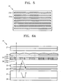
FIG. 4 schematically illustrates the cross-sectional view of a reflective polarizer used for the stereo image display apparatus ofFIGS. 3A and3B ; -
FIG. 5 schematically illustrates the plan view of the reflective polarizer used for the stereo image display apparatus ofFIGS. 3A and3B ; -
FIGS. 6A and6B schematically illustrate the structure and operation of a stereo image display apparatus having an improved light use efficiency; -
FIG. 7 schematically illustrates the plan view of a reflective polarizer array used for the stereo image display apparatus ofFIGS. 6A and6B ; -
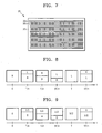
FIG. 8 illustrates the process of scanning images for the left and right eyes in a display panel according to the passage of time; and -
FIG. 9 illustrates an example of a switching operation of a polarization switch in the display panel. -
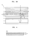
FIGS. 3A and3B schematically illustrate the structure and operation of a stereo image display apparatus having an improved light use efficiency according to an exemplary embodiment of the present invention. Referring toFIGS. 3A and3B , animage display apparatus 20 according to an exemplary embodiment includes abacklight unit 21 having areflection panel 28 installed at a bottom surface thereof, apolarization panel 22 transmitting light only in a particular polarization direction of the light emitted from thebacklight unit 21, apolarization switch 23 converting the polarization direction of the incident light according to electric control, abirefringent element array 24 having a plurality of first and secondbirefringent elements reflective polarizer 25 transmitting only light of a particular polarization direction of the light passing through thebirefringent element array 24 and reflecting light of the other polarization direction, alens array 26 separating the incident light into a left eye view zone and a right eye view zone, and adisplay panel 27 displaying an image. - The
polarization panel 22 may be a general absorptive polarizer that transmits light of a particular polarization direction and absorbs the other light of the light emitted from thebacklight unit 21. However, to increase a light use efficiency, a reflective polarization film having a multilayer structure such as a dual brightness enhancement film (DBEF) which transmits the light of a particular polarization direction and reflects the others may be used as thepolarization panel 22. - According to the present invention, the
display panel 27 is a non-emissive display such as an LCD panel using thebacklight unit 21 as a light source. As it will be described later, thedisplay panel 27 according to the present invention alternately displays a right eye image and a left eye image in a 3D mode according to the passage of time. For example, thedisplay panel 27 operates such that the right eye image is displayed at a first frame and the left eye image is displayed at a second frame. Thus, for a user to view the right eye image and the left eye image without flickering, a high response speed LCD having a refresh rate of 120 Hz or higher may be used as thedisplay panel 27. - Also, in the present exemplary embodiment, the
polarization switch 23 may switch between first through third states respectively having a difference of 45° in the polarization direction of light passing through thepolarization switch 23. For example, thepolarization switch 23 has a first state in which the polarization direction of the incident light is not changed, a second state in which the polarization direction of the incident light is changed by 45°, and a third state in which the polarization direction of the incident light is changed by 90°. In each state of thepolarization switch 23, the change angle of the polarization direction is exemplary and thepolarization switch 23 can be designed to be different according to the polarization characteristic of thepolarization panel 22 and thebirefringent element array 24. It is sufficient that the difference in the polarization direction of the transmission light when thepolarization switch 23 is in each of the first, second, and third states has a difference of 45°. Thepolarization switch 23 is formed of an electrically controllable device having three anisotropic statuses according to the amount of an applied voltage. For example, a liquid crystal retarder can be used as thepolarization switch 23. When thepolarization switch 23 is the liquid crystal retarder, for example, the incident light is not delayed in the first state, the phase of the incident light is delayed by 1/4 wavelength (λ/4) in the second state, and the phase of the incident light is delayed by 1/2 wavelength (λ/2) in the third state. - As shown in
FIGS. 3A and3B , thebirefringent element array 24 according to the present exemplary embodiment has the first and secondbirefringent elements FIGS. 3A and3B , the first and secondbirefringent elements image display apparatus 20 and arranged alternately in the horizontal direction. According to the present exemplary embodiment, thebirefringent element array 24 changes the polarization direction of the incident light such that the polarization directions of the light passing through the first and secondbirefringent elements - For example, the first and second
birefringent elements birefringent element 24a and the retarder forming the secondbirefringent element 24b are configured to have a phase delay difference of λ/2. For example, the firstbirefringent element 24a does not delay phase while the secondbirefringent element 24b delays phase by λ/2. In another exemplary embodiment, the first birefringent 24a delays the phase by -λ/4 while the secondbirefringent element 24b delays phase by +λ/4. In yet another exemplary embodiment, the first and secondbirefringent elements birefringent element 24a and a rotator forming the secondbirefringent element 24b are configured to have a rotation angle difference of 90. For example, the firstbirefringent element 24a does not rotate the incident light while the secondbirefringent element 24b rotates the incident light by 90°. Also, the firstbirefringent element 24a rotates the incident light by -45° while the secondbirefringent element 24b rotates the incident light by +45°. - The
reflective polarizer 25 transmits only light of a particular polarization direction and reflects light of a different polarization direction of the light passing through thebirefringent element array 24. In particular, when an LCD panel is used as thedisplay panel 27, thereflective polarizer 25 transmits light of the same polarization direction as that of a rear polarizer (not shown) arranged at the rear surface of the LCD panel and reflects light of a polarization direction perpendicular to the polarization direction of the rear polarizer. However, to simplify the structure of theimage display apparatus 20, the rear polarizer of the LCD panel can be replaced by thereflective polarizer 25. - To provide quality polarization light to the
display panel 27, the polarization extinction ratio of thereflective polarizer 25 may be very high. For this purpose, a wire-grid polarizer, for example, can be used as thereflective polarizer 25. As shown inFIG. 4 , the wire-grid polarizer is formed by arranging a plurality of thinconductive metal wires 25b on atransparent substrate 25a in parallel at a predetermined interval. In general, as the arrangement period Λ of themetal wire 25b is longer than the wavelength of the incident light, the wire-grid polarizer has more of a characteristic as a diffraction grid. Also, as the arrangement period Λ of themetal wire 25b is shorter than the wavelength of the incident light, the wire-grid polarizer has more of a characteristic as a polarizer. When the wire-grid polarizer has a characteristic as a polarizer, the wire-grid polarizer reflects the light having a polarization direction parallel to themetal wire 25b and transmits light of a polarization direction perpendicular to themetal wire 25b. For example, when themetal wire 25b is appropriately arranged, an S-polarization light having a polarization direction parallel to an incident plane is reflected by the wire-grid polarizer and a P-polarization light having a polarization direction perpendicular to the incident plane can pass through the wire-grid polarizer. As the arrangement period Λ of themetal wire 25b decreases, the polarization extinction ratio increases by geometric progression. - Thus, according to the present exemplary embodiment shown in
FIGS. 3A and3B , a wire-grid polarizer in which themetal wires 25b are arranged in the same direction over the overall area of thetransparent substrate 25a can be used as thereflective polarizer 25, as shown inFIG. 5 . In this case, thereflection polarizer 25 can provide quality polarization light to thedisplay panel 27. - According to the present exemplary embodiment, the light passing through the
polarization switch 23 and thebirefringent element array 24 having the above structure can have one of the following polarization directions according to the state of thepolarization switch 23. That is, (i) the light passing through the firstbirefringent element 24a passes through thereflective polarizer 25 and the light passing through the secondbirefringent element 24b is reflected by thereflective polarizer 25, (ii) the light passing through the firstbirefringent element 24a is reflected by thereflective polarizer 25 and the light passing through the secondbirefringent element 24b passes through thereflective polarizer 25, and (iii) the light passing through both of the first and secondbirefringent elements reflective polarizer 25. - The
lens array 26 is formed by arranging a plurality of vertical lenticular lens elements in a horizontal direction. Each of the lenticular lens elements is formed in the vertical direction of theimage display apparatus 20 parallel to thebirefringent elements birefringent element array 24. Thelens array 26 separates the incident light into the left eye view zone and the right eye view zone. The light passing through thelens array 26 forms an image by being separated in the left eye view zone and the right eye view zone at a viewing distance. For example, the light emitted from the firstbirefringent element 24a proceeds toward the right eye view zone through thelens array 26 and the light emitted from the secondbirefringent element 24b proceeds toward the left eye view zone through thelens array 26. - As it is well known, the interval between the left eye view zone and the right eye view zone at the viewing distance may be about 65 mm. For this purpose, the pitch between the lenticular lens elements of the
lens array 26 is the same as, or slightly smaller than, that between the first and secondbirefringent elements birefringent element array 24. That is, the width of a single lenticular lens element is the same as, or slightly smaller than, sum of the width of the firstbirefringent element 24a and the width of the secondbirefringent element 24b. Also, the distance between thelens array 26 and thebirefringent element array 24 may be the same as, or slightly greater than, the focal length of the lenticular lens element. - The operation of a highly efficient 2D/3D
switchable display apparatus 20 configured as above according to the present invention will be described in detail with reference toFIGS. 3A and3B . - For the convenience of explanation, it is assumed that the
polarization panel 22 is a DBEF that transmits a P-polarization light indicated by "•" in the drawing and reflects the S-polarization light indicated by "↔" in the drawing and that thepolarization switch 23 is a liquid crystal retarder that has a first state in which the polarization direction of the incident light is not changed, a second state in which the polarization direction of the incident light is changed by 45° or delayed by 1/4 wavelength (λ/4), and a third state in which the polarization direction of the incident light is changed by 90° or delayed by 1/2 wavelength (λ/2). Also, it is assumed that the firstbirefringent element 24a is a retarder that delays phase by half wavelength (λ/2) and the secondbirefringent element 24b is a retarder that does not delay phase. Also, it is assumed that thereflective polarizer 25 is a wire-grid polarizer that transmits the P-polarization light and reflects the S-polarization light. - First, the
backlight unit 21 emits an unpolarized light. The P-polarization light of the light emitted from thebacklight unit 21 passes through thepolarization panel 22 and is incident on thepolarization switch 23. The S-polarization light is reflected by thepolarization panel 22 and then by thereflection panel 28 at the bottom of thebacklight unit 21 so as to be reused. Although it is not shown, thebacklight unit 21 includes a diffusion panel to uniformly emit light. The S-polarization light reflected by thereflection panel 28 is diffused by the diffusion panel and can be changed to the unpolarized light. - As shown in
FIG. 3A , when thepolarization switch 23 is in the first state, the polarization direction of the light passing through thepolarization panel 22 and incident on thepolarization switch 23 is not changed. Thus, the light passing through thepolarization switch 23 is still the P-polarization light. Then, the P-polarization light passes through each of the first and secondbirefringent elements FIG. 3A , the light passing through the firstbirefringent element 24a is delayed by the half wavelength (λ/2) and changed to the S-polarization. However, since the phase of the light passing through the secondbirefringent element 24b is not changed, the light maintains the P-polarization. Then, the light passing through each of the first and secondbirefringent elements reflective polarizer 25. Since the light passing through the firstbirefringent element 24a is the S-polarization light, the light is reflected by thereflective polarizer 25 and incident on the firstbirefringent element 24a. The reflected light is changed to the P-polarization by the firstbirefringent element 24a and reflected by thereflection panel 28 of thebacklight unit 21 so as to be reused. On the other hand, since the light passing through the secondbirefringent element 24b is the P-polarization light, the light passes through thereflective polarizer 25 and is incident on thelens array 26. Then, the light proceeds toward the left eye view zone by thelens array 26. Thus, in this case, when thedisplay panel 27 displays the left eye image, the user recognizes only the left eye image through his/her left eye. - As shown in
FIG. 3B , when thepolarization switch 23 is in the third state, the P-polarization light passing through thepolarization panel 22 and incident on thepolarization switch 23 is changed to the S-polarization light as the polarization direction changes. Then, the S-polarization light passes through each of the first and secondbirefringent elements FIG. 3B , the phase of the light passing through the firstbirefringent element 24a is delayed by half wavelength (λ/2) so that the light is changed to the P-polarization. However, the phase of the light passing through the secondbirefringent element 24b is not changed so that the light remains unchanged as the S-polarization light. Then, the light passing through each of the first and secondbirefringent elements reflective polarizer 25. Since the light passing through the secondbirefringent element 24b is the S-polarization light, the light is reflected by thereflective polarizer 25 and passes again through the secondbirefringent element 24b. The reflected S-polarization light is changed again to the P-polarization by thepolarization switch 23 and reflected by thereflection panel 28 of thebacklight unit 21 so as to be reused. On the other hand, since the light passing through the firstbirefringent element 24a is the P-polarization light, the light passes through thereflective polarizer 25 and incident on thelens array 26. Then, the light proceeds toward the right eye view zone by thelens array 26. Thus, in this case, when thedisplay panel 27 displays the right eye image, the user recognizes only the right eye image through his/her right eye. - According to the above-described principle, in the 3D mode, when the
display panel 27 displays the left eye image and the right eye image, thepolarization switch 23 is respectively switched to the first state and the third state so that the user can view a stereo image. Thedisplay panel 27 needs to display the right eye image and the left eye image at a very fast time interval so that the user cannot sense flickering. Thus, as described above, a high response speed LCD having a refresh rate of about 120 Hz or higher may be used as thedisplay panel 27. Also thepolarization switch 23 needs to be switched very fast in synchronism with thedisplay panel 27. Thus, a liquid crystal retarder that is electrically controllable may be used as thepolarization switch 23. Presently, a liquid crystal retarder having a switching speed of about 180 Hz is provided at a relatively low price. - In the meantime, the 2D mode can be embodied in two methods. For example, while the
polarization switch 23 is repeatedly switched between the first and third states, thedisplay panel 27 continuously displays the same image by two frames. Then, since the same image is continuously recognized by the right eye and the left eye of the user, the user can view a 2D image. - In another method, while the
polarization switch 23 is fixed to the second state, thedisplay panel 27 displays a 2D image at a typical speed of about 60 Hz. When thepolarization switch 23 is in the second state, the light passing through thepolarization switch 23 has both a P-polarization component and an S-polarization component. The light passing through each of the first and secondbirefringent elements birefringent elements reflective polarizer 25 and incident on thelens array 26. Then, the P-polarization light incident on thelens array 26 from the firstbirefringent element 24a passes through thedisplay panel 27 and proceeds toward the right eye view zone. The P-polarization light incident on thelens array 26 from the secondbirefringent element 24b passes through thedisplay panel 27 and proceeds toward the left eye view zone. Thus, when thedisplay panel 27 displays a 2D image, the user can view the 2D image through his/her left and right eyes. -
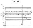
FIGS. 6A and6B schematically illustrate the structure and operation of a stereo image display apparatus having an improved light use efficiency according to an arrangement not an embodiment of the present invention, but useful for understanding. Compared to theimage display apparatus 20 ofFIGS. 3A and3B where thereflective polarizer 25 is arranged between thelens array 26 and thebirefringent element array 24, an image display apparatus 20' according to the present exemplary embodiment is different in that thereflective polarizer array 29 is arranged between thebirefringent device array 24 and thepolarization switch 23. Thereflective polarizer array 29 has a structure in which first and secondreflective polarizers reflective polarizer 29a is a wire-grid polarizer that transmits S-polarization light and reflects P-polarization light. The secondreflective polarizer 29b is a wire-grid polarizer that transmits the P-polarization light and reflects S-polarization light.FIG. 7 schematically illustrates the plain view of thereflective polarizer array 29. As shown inFIG. 7 , thereflective polarizer array 29 can be formed by periodically arrangingmetal wires transparent substrate 30c. - Also, the first and second
reflective polarizer reflective polarizer array 29 are respectively arranged to correspond to the first and secondbirefringent elements birefringent element array 24. That is, the firstreflective polarizer 29a corresponds to the firstbirefringent element 24a and the secondreflection polarization panel 29b corresponds to the secondbirefringent element 24b. Thus, the widths of the first and secondreflective polarizer reflective polarizer array 29 match the widths of the first and secondbirefringent elements birefringent element array 24. - In this structure, as shown in
FIG. 6A , when thepolarization switch 23 is in the first state, the P-polarization light passing through thepolarization switch 23 is incident on each of the first and secondreflective polarizer FIG. 6A , the P-polarization light incident on the firstreflective polarizer 29a is reflected by the firstreflective polarizer 29a and then reflected by thereflection panel 28 of thebacklight unit 21 so as to be reused. On the other hand, the P-polarization light incident on the secondreflective polarizer 29b passes through the secondreflection polarization panel 29b and is incident on the secondbirefringent element 24b. Then, the P-polarization light passes through the secondbirefringent element 24b without a change in the polarization direction and proceeds toward the left eye view zone by means of thelens array 26. - Also, as shown in
FIG. 6B , when thepolarization switch 23 is in the third state, the polarization direction of the P-polarization light incident on thepolarization switch 23 is changed to the S-polarization light. The S-polarization light is incident on each of the first and secondreflective polarizers FIG. 6B , the S-polarization light incident on the firstreflective polarizer 29a passes through the firstreflective polarizer 29a and incident on the firstbirefringent element 24a. The light is changed to the P-polarization light by the firstbirefringent element 24a and proceeds toward the right eye view zone by means of thelens array 26. On the other hand, the S-polarization light incident on the secondreflective polarizer 29b is reflected by the secondreflective polarizer 29b and incident on thepolarization switch 23. Then, the light is changed to the P-polarization light by thepolarization switch 23 and reflected by thereflection panel 28 of thebacklight unit 21 so as to be reused. - As a result, in the 3D mode, when the
display panel 27 displays the left eye image, thepolarization switch 23 is switched to the first state. When thedisplay panel 27 displays the right eye image, thepolarization switch 23 is switched to the third state. Thus, the user can view a stereo image. - In the meantime, the
display panel 27 does not display the right eye image at once and then the left eye image, but sequentially scans continuous images from the top to bottom of a screen, as shown inFIG. 8 . As a result, the time when the left eye image and the right eye image share a single screen exists so that crosstalk detected as the left eye image and the right eye image are mixed can occur. - Thus, to prevent crosstalk, the
polarization switch 23 can be divided into a plurality of horizontal segments that are sequentially switched in synchronism with the vertical scanning time of thedisplay panel 27. The respective horizontal segments of thepolarization switch 23 may be independently switched and arranged in the vertical direction. In this case, each of the horizontal segments of thepolarization switch 23 is switched to the first state when corresponding pixel lines of thedisplay panel 27 display an image of a frame and then to the third state when an image of the next frame is displayed.
FIG. 9 illustrates an example of a switching operation of a polarization switch in the display panel. InFIG. 9 , thepolarization switch 23 is a four-dividedpolarization switch 23 divided into four segments that does not delay the incident light in the first state and delays the incident light by 1/2 wavelength (λ/2) in the third state. As shown inFIG. 9 , thepolarization switch 23 is in the first state at time "0" and in the third state at time "T". Thepolarization switch 23 is continuously changed from the first state to the third state in synchronism with thedisplay panel 27 between the time "0" and "T". The switching operation of thepolarization switch 23 is controlled to be accurately synchronized with the time that thedisplay panel 27 displays an image. As a result, during the time when the left eye image and the right eye image share a screen, crosstalk hardly occurs and the left eye image and the right eye image can be accurately separated. - As described above, according to the present invention, when a stereo image is produced, the reduction of resolution and brightness can be prevented. That is, since the display panel alternately displays the left eye image and the right eye image at high speed, the reduction of resolution can be prevented. Also, as the light is reused using the reflective polarizer, a light use efficiency is improved so that brightness can be improved compared to the conventional technology. Furthermore, according to the present invention, a general 2D image can be displayed in a 2D mode or a stereo image can be displayed in a 3D mode, as necessary.
- Although a few preferred embodiments have been shown and described, it will be appreciated by those skilled in the art that various changes and modifications might be made without departing from the scope of the invention, as defined in the appended claims.
Claims (10)
- An image display apparatus for a 2D/3D switchable display (20) comprising:a backlight unit (21) having a reflection panel (28) at the back thereof;a polarization panel (22) arranged to transmit only light of a particular polarization direction emitted from the front of the backlight unit (21) in a first direction;a polarization switch (23) operable to transmit and change a polarization direction by 90° of light from the polarization panel incident upon the polarization switch (23);a birefringent element array (24) comprising a plurality of first and second birefringent elements (24a, 24b) alternately arrayed in a second direction perpendicular to said first direction and each arranged to change a polarization direction of polarized light transmitted by said polarization switch and incident upon the first and second birefringent elements (24a, 24b) respectively to make the polarization direction of light passed through the first and second birefringent elements (24a, 24b) perpendicular to each other;a reflective polarizer panel (25) arranged to transmit only light of a particular polarization direction passed through the birefringent element array (24) and to reflect light of the other polarization direction of the light passed through the birefringent element array (24);a lens array (26) having lenticular elements arrayed in said second direction and arranged to separate light transmitted by the reflection polarizer and incident upon the lens array (26) from a first birefringent element into a first view zone and from a second birefringent element into a second view zone; anda display panel (27) operable to display an image using the light separated by the lens array.
- The image display apparatus (20) of claim 1, wherein the polarization switch (23) is operable to be switched among first through third states in which the polarization direction of the light incident upon the polarization switch (23) is changed differently.
- The image display apparatus (20) of claim 2, wherein the polarization switch (23) is operable to be switched among a first state in which the polarization direction of the light incident upon the polarization switch (23) is not changed, a second state in which the polarization direction of the light incident upon the polarization switch (23) is changed by 45°, and a third state in which the polarization direction of the light incident upon the polarization switch (23) is changed by 90°.
- The image display apparatus (20) of claim 1, wherein said second direction is a horizontal direction and the birefringent element array (24) is formed by alternately arranging in a horizontal direction the first and second birefringent elements (24a, 24b) that are vertically elongated.
- The image display apparatus (20) of claim 4, wherein each of the first and second birefringent elements (24a, 24b) is formed of a retarder arranged to delay incident light by a phase and wherein a phase delay difference between a retarder forming the first birefringent element and a retarder forming the second birefringent element is λ/2.
- The image display apparatus (20) of claim 4, wherein each of the first and second birefringent elements (24a, 24b) is formed of a rotator arranged to rotate a polarization direction of incident light by an angle and a rotation angle difference between a rotator forming the first birefringent element and a rotator forming the second birefringent element is 90°.
- The image display apparatus (20) of claim 4, wherein the lens array (26) is formed by arranging a plurality of lenticular lens elements that extend vertically, and are parallel to the plurality of the first and the second birefringent elements of the birefringent element array (24) arrayed in a horizontal direction as said second direction.
- The image display apparatus (20) of claim 1, wherein the reflective polarizer is a wire-grid polarizer formed of metal wires arranged parallel to one another at a constant interval.
- The image display apparatus (20) of claim 1, wherein the polarization panel (22) transmits only light of a particular polarization direction of the light emitted from the backlight unit (21) and reflects light of the other polarization direction of the light emitted from the backlight unit (21).
- The image display apparatus (20) of claim 1, wherein the polarization switch (23) is divided into a plurality of horizontal segments that are arrayed in a vertical direction, perpendicular to said first and second directions, and are sequentially switched in synchronism with a vertical scanning time of the display panel (27).
Applications Claiming Priority (1)
| Application Number | Priority Date | Filing Date | Title |
|---|---|---|---|
| KR1020070007651A KR101299728B1 (en) | 2007-01-24 | 2007-01-24 | High efficient 2D-3D switchable display apparatus |
Publications (2)
| Publication Number | Publication Date |
|---|---|
| EP1950980A1 EP1950980A1 (en) | 2008-07-30 |
| EP1950980B1 true EP1950980B1 (en) | 2013-04-10 |
Family
ID=39125190
Family Applications (1)
| Application Number | Title | Priority Date | Filing Date |
|---|---|---|---|
| EP07122930.6A Not-in-force EP1950980B1 (en) | 2007-01-24 | 2007-12-11 | Autostereoscopic 2D/3D switchable display apparatus with high light efficiency, employing a lenticular screen and time-multiplexing of 3D-views |
Country Status (4)
| Country | Link |
|---|---|
| US (1) | US7522340B2 (en) |
| EP (1) | EP1950980B1 (en) |
| KR (1) | KR101299728B1 (en) |
| CN (1) | CN101231414B (en) |
Families Citing this family (30)
| Publication number | Priority date | Publication date | Assignee | Title |
|---|---|---|---|---|
| KR100813977B1 (en) * | 2005-07-08 | 2008-03-14 | 삼성전자주식회사 | High resolution 2D-3D switchable autostereoscopic display apparatus |
| JP5012729B2 (en) * | 2008-08-08 | 2012-08-29 | ソニー株式会社 | Display panel module, semiconductor integrated circuit, pixel array driving method, and electronic apparatus |
| KR20100033067A (en) | 2008-09-19 | 2010-03-29 | 삼성전자주식회사 | Image display apparatus and method for both 2d and 3d image |
| WO2010075340A1 (en) | 2008-12-22 | 2010-07-01 | 3M Innovative Properties Company | Multilayer optical films having side-by-side mirror/polarizer zones |
| KR100989126B1 (en) * | 2009-02-05 | 2010-10-20 | 삼성모바일디스플레이주식회사 | Electronic imaging device and the method thereof |
| KR101640839B1 (en) * | 2009-06-01 | 2016-07-20 | 삼성디스플레이 주식회사 | Method for displaying 3-dimensional image and display device for perform the same |
| US8325409B2 (en) * | 2009-06-15 | 2012-12-04 | Qualcomm Mems Technologies, Inc. | Periscoping vanes for smart windows |
| JP4763822B2 (en) * | 2009-09-30 | 2011-08-31 | パナソニック株式会社 | Video signal processing apparatus and video signal processing method |
| KR101279122B1 (en) * | 2009-11-24 | 2013-06-26 | 엘지디스플레이 주식회사 | Image display device |
| JP2011118302A (en) * | 2009-12-07 | 2011-06-16 | Toshiba Mobile Display Co Ltd | Display device, shutter spectacles and display system |
| KR101777121B1 (en) * | 2010-07-28 | 2017-09-12 | 엘지디스플레이 주식회사 | Stereoscopic Image Display Device |
| US8848040B2 (en) * | 2010-10-08 | 2014-09-30 | 3Dv Co., Ltd. | 3D display system with active shutter plate |
| CN102141714B (en) * | 2011-03-31 | 2013-10-23 | 昆山龙腾光电有限公司 | Display device |
| TWI456308B (en) * | 2011-06-01 | 2014-10-11 | Wintek Corp | Display device and backlight module thereof |
| CN202443187U (en) * | 2012-02-27 | 2012-09-19 | 北京京东方光电科技有限公司 | Three-dimensional spectacles and control chip thereof |
| KR101915623B1 (en) | 2012-04-18 | 2018-11-08 | 삼성디스플레이 주식회사 | Liquid crytal lens panel, display device having the same |
| US9384581B2 (en) | 2012-04-20 | 2016-07-05 | Affirmation, Llc | Systems and methods for real-time conversion of video into three-dimensions |
| CN103851407A (en) * | 2012-11-28 | 2014-06-11 | 群康科技(深圳)有限公司 | Backlight module and liquid crystal display device |
| CN105009582B (en) * | 2013-03-11 | 2017-09-15 | 皇家飞利浦有限公司 | Transparent display |
| CN103605214A (en) * | 2013-11-21 | 2014-02-26 | 深圳市华星光电技术有限公司 | Stereoscopic display device |
| CN104238125A (en) * | 2014-03-31 | 2014-12-24 | 何东阳 | Three-dimensional display device |
| TWI497116B (en) * | 2014-05-12 | 2015-08-21 | Au Optronics Corp | 3d image display device and 3d image display method |
| KR102176592B1 (en) * | 2014-05-16 | 2020-11-09 | 삼성전자주식회사 | Spatial light modulator including nano antenna electrode and display apparatus including the spatial light modulator |
| CN104216134A (en) * | 2014-09-28 | 2014-12-17 | 四川大学 | High-brightness 2D/3D switchable integration imaging display device |
| CN104765158B (en) | 2015-05-06 | 2017-08-29 | 合肥京东方光电科技有限公司 | Parallax baffle and display device |
| CN105700058A (en) * | 2016-04-05 | 2016-06-22 | 武汉华星光电技术有限公司 | Metal wire grating brightness enhance film for display backlight and preparation method for metal wire grating brightness enhance film |
| CN105700163A (en) * | 2016-04-07 | 2016-06-22 | 武汉华星光电技术有限公司 | Cylindrical lens film and 3D display device |
| CN106707396A (en) * | 2017-01-24 | 2017-05-24 | 宁波视睿迪光电有限公司 | Phase delay film and three-dimensional display device |
| CN109188700B (en) * | 2018-10-30 | 2021-05-11 | 京东方科技集团股份有限公司 | Optical display system and AR/VR display device |
| TWI812011B (en) * | 2022-02-16 | 2023-08-11 | 友達光電股份有限公司 | Display device |
Family Cites Families (7)
| Publication number | Priority date | Publication date | Assignee | Title |
|---|---|---|---|---|
| US6804058B1 (en) * | 1993-12-21 | 2004-10-12 | 3M Innovative Properties Company | Electroluminescent light source and display incorporating same |
| US6515785B1 (en) * | 1999-04-22 | 2003-02-04 | 3M Innovative Properties Company | Optical devices using reflecting polarizing materials |
| KR20060042481A (en) | 2004-11-09 | 2006-05-15 | 엘지전자 주식회사 | Liquid crystal display with reflective polarizer |
| KR20060073371A (en) * | 2004-12-24 | 2006-06-28 | 엘지.필립스 엘시디 주식회사 | Backlight unit and liquid crystal display module having the same |
| KR101086412B1 (en) | 2005-04-04 | 2011-11-25 | 삼성전자주식회사 | Stereo-scopic display apparatus capable of switching 2D/3D image |
| KR20060135450A (en) * | 2005-06-25 | 2006-12-29 | 삼성전자주식회사 | 2d and 3d imaging display |
| KR100813977B1 (en) | 2005-07-08 | 2008-03-14 | 삼성전자주식회사 | High resolution 2D-3D switchable autostereoscopic display apparatus |
-
2007
- 2007-01-24 KR KR1020070007651A patent/KR101299728B1/en active IP Right Grant
- 2007-10-22 US US11/876,177 patent/US7522340B2/en active Active
- 2007-12-11 EP EP07122930.6A patent/EP1950980B1/en not_active Not-in-force
- 2007-12-13 CN CN200710199453.1A patent/CN101231414B/en not_active Expired - Fee Related
Also Published As
| Publication number | Publication date |
|---|---|
| EP1950980A1 (en) | 2008-07-30 |
| US20080174848A1 (en) | 2008-07-24 |
| CN101231414A (en) | 2008-07-30 |
| KR101299728B1 (en) | 2013-08-22 |
| US7522340B2 (en) | 2009-04-21 |
| KR20080069869A (en) | 2008-07-29 |
| CN101231414B (en) | 2015-04-22 |
Similar Documents
| Publication | Publication Date | Title |
|---|---|---|
| EP1950980B1 (en) | Autostereoscopic 2D/3D switchable display apparatus with high light efficiency, employing a lenticular screen and time-multiplexing of 3D-views | |
| EP1965245A1 (en) | Stereoscopic Display Apparatus | |
| KR100728204B1 (en) | Display device capable of displaying 2-dimensional and 3-dimensional images | |
| EP2014103B1 (en) | Multiview autostereoscopic display | |
| EP1942681B1 (en) | Highly efficient 2D/3D switchable autostereoscopic display device | |
| EP2014104B1 (en) | High resolution autostereoscopic display apparatus with interlaced image | |
| US7986375B2 (en) | Multi-view autostereoscopic display device having particular driving means and driving method | |
| EP2062444B1 (en) | Multi-view autostereoscopic display with improved resolution | |
| JP4159045B2 (en) | Autostereoscopic display | |
| EP1528414B1 (en) | Direct view LC display | |
| US20080231952A1 (en) | Highly efficient 2d/3d switchable display device | |
| JP3570104B2 (en) | Liquid crystal display | |
| KR20130057374A (en) | Autostereoscropic display device | |
| JPH05284542A (en) | Three-dimensional picture/two-dimensional picture coexistence type display device | |
| KR0176520B1 (en) | 3-dimension projection apparatus | |
| JP2008281605A (en) | Liquid crystal display panel, stereoscopic image display device and liquid crystal touch panel device | |
| KR101782006B1 (en) | polarizing glasses for watching 3 dimensional stereography image displayed and 3 dimensional stereography image display system having the same | |
| JP2003202517A (en) | Stereoscopic image display device | |
| KR20000039515A (en) | Display device for three dimensional image | |
| JPH0921980A (en) | Picture displaying method and picture display device using same | |
| KR101299184B1 (en) | 3 dimensional stereography image displayable system | |
| TWI420150B (en) | Stereoscopic image display | |
| JP2013003572A (en) | Stereoscopic display apparatus |
Legal Events
| Date | Code | Title | Description |
|---|---|---|---|
| PUAI | Public reference made under article 153(3) epc to a published international application that has entered the european phase |
Free format text: ORIGINAL CODE: 0009012 |
|
| AK | Designated contracting states |
Kind code of ref document: A1 Designated state(s): AT BE BG CH CY CZ DE DK EE ES FI FR GB GR HU IE IS IT LI LT LU LV MC MT NL PL PT RO SE SI SK TR |
|
| AX | Request for extension of the european patent |
Extension state: AL BA HR MK RS |
|
| 17P | Request for examination filed |
Effective date: 20090115 |
|
| 17Q | First examination report despatched |
Effective date: 20090219 |
|
| AKX | Designation fees paid |
Designated state(s): AT BE BG CH CY CZ DE DK EE ES FI FR GB GR HU IE IS IT LI LT LU LV MC MT NL PL PT RO SE SI SK TR |
|
| RAP1 | Party data changed (applicant data changed or rights of an application transferred) |
Owner name: SAMSUNG ELECTRONICS CO., LTD. |
|
| GRAP | Despatch of communication of intention to grant a patent |
Free format text: ORIGINAL CODE: EPIDOSNIGR1 |
|
| RIN1 | Information on inventor provided before grant (corrected) |
Inventor name: HWANG, SEON-DEOK Inventor name: CHA, KYUNG-HOON Inventor name: KOO, JAE-PHIL Inventor name: CHESTAK, SERGEY Inventor name: KIM, DAE-SIK |
|
| GRAS | Grant fee paid |
Free format text: ORIGINAL CODE: EPIDOSNIGR3 |
|
| GRAA | (expected) grant |
Free format text: ORIGINAL CODE: 0009210 |
|
| AK | Designated contracting states |
Kind code of ref document: B1 Designated state(s): AT BE BG CH CY CZ DE DK EE ES FI FR GB GR HU IE IS IT LI LT LU LV MC MT NL PL PT RO SE SI SK TR |
|
| REG | Reference to a national code |
Ref country code: GB Ref legal event code: FG4D |
|
| REG | Reference to a national code |
Ref country code: AT Ref legal event code: REF Ref document number: 606573 Country of ref document: AT Kind code of ref document: T Effective date: 20130415 Ref country code: CH Ref legal event code: EP |
|
| REG | Reference to a national code |
Ref country code: IE Ref legal event code: FG4D |
|
| REG | Reference to a national code |
Ref country code: DE Ref legal event code: R096 Ref document number: 602007029621 Country of ref document: DE Effective date: 20130606 |
|
| PG25 | Lapsed in a contracting state [announced via postgrant information from national office to epo] |
Ref country code: SI Free format text: LAPSE BECAUSE OF FAILURE TO SUBMIT A TRANSLATION OF THE DESCRIPTION OR TO PAY THE FEE WITHIN THE PRESCRIBED TIME-LIMIT Effective date: 20130410 |
|
| REG | Reference to a national code |
Ref country code: NL Ref legal event code: T3 |
|
| REG | Reference to a national code |
Ref country code: AT Ref legal event code: MK05 Ref document number: 606573 Country of ref document: AT Kind code of ref document: T Effective date: 20130410 |
|
| REG | Reference to a national code |
Ref country code: LT Ref legal event code: MG4D |
|
| PG25 | Lapsed in a contracting state [announced via postgrant information from national office to epo] |
Ref country code: AT Free format text: LAPSE BECAUSE OF FAILURE TO SUBMIT A TRANSLATION OF THE DESCRIPTION OR TO PAY THE FEE WITHIN THE PRESCRIBED TIME-LIMIT Effective date: 20130410 Ref country code: IS Free format text: LAPSE BECAUSE OF FAILURE TO SUBMIT A TRANSLATION OF THE DESCRIPTION OR TO PAY THE FEE WITHIN THE PRESCRIBED TIME-LIMIT Effective date: 20130810 Ref country code: PT Free format text: LAPSE BECAUSE OF FAILURE TO SUBMIT A TRANSLATION OF THE DESCRIPTION OR TO PAY THE FEE WITHIN THE PRESCRIBED TIME-LIMIT Effective date: 20130812 Ref country code: LT Free format text: LAPSE BECAUSE OF FAILURE TO SUBMIT A TRANSLATION OF THE DESCRIPTION OR TO PAY THE FEE WITHIN THE PRESCRIBED TIME-LIMIT Effective date: 20130410 Ref country code: FI Free format text: LAPSE BECAUSE OF FAILURE TO SUBMIT A TRANSLATION OF THE DESCRIPTION OR TO PAY THE FEE WITHIN THE PRESCRIBED TIME-LIMIT Effective date: 20130410 Ref country code: SE Free format text: LAPSE BECAUSE OF FAILURE TO SUBMIT A TRANSLATION OF THE DESCRIPTION OR TO PAY THE FEE WITHIN THE PRESCRIBED TIME-LIMIT Effective date: 20130410 Ref country code: BE Free format text: LAPSE BECAUSE OF FAILURE TO SUBMIT A TRANSLATION OF THE DESCRIPTION OR TO PAY THE FEE WITHIN THE PRESCRIBED TIME-LIMIT Effective date: 20130410 Ref country code: GR Free format text: LAPSE BECAUSE OF FAILURE TO SUBMIT A TRANSLATION OF THE DESCRIPTION OR TO PAY THE FEE WITHIN THE PRESCRIBED TIME-LIMIT Effective date: 20130711 Ref country code: ES Free format text: LAPSE BECAUSE OF FAILURE TO SUBMIT A TRANSLATION OF THE DESCRIPTION OR TO PAY THE FEE WITHIN THE PRESCRIBED TIME-LIMIT Effective date: 20130721 |
|
| PG25 | Lapsed in a contracting state [announced via postgrant information from national office to epo] |
Ref country code: CY Free format text: LAPSE BECAUSE OF FAILURE TO SUBMIT A TRANSLATION OF THE DESCRIPTION OR TO PAY THE FEE WITHIN THE PRESCRIBED TIME-LIMIT Effective date: 20130410 Ref country code: PL Free format text: LAPSE BECAUSE OF FAILURE TO SUBMIT A TRANSLATION OF THE DESCRIPTION OR TO PAY THE FEE WITHIN THE PRESCRIBED TIME-LIMIT Effective date: 20130410 Ref country code: LV Free format text: LAPSE BECAUSE OF FAILURE TO SUBMIT A TRANSLATION OF THE DESCRIPTION OR TO PAY THE FEE WITHIN THE PRESCRIBED TIME-LIMIT Effective date: 20130410 Ref country code: BG Free format text: LAPSE BECAUSE OF FAILURE TO SUBMIT A TRANSLATION OF THE DESCRIPTION OR TO PAY THE FEE WITHIN THE PRESCRIBED TIME-LIMIT Effective date: 20130710 |
|
| PG25 | Lapsed in a contracting state [announced via postgrant information from national office to epo] |
Ref country code: CZ Free format text: LAPSE BECAUSE OF FAILURE TO SUBMIT A TRANSLATION OF THE DESCRIPTION OR TO PAY THE FEE WITHIN THE PRESCRIBED TIME-LIMIT Effective date: 20130410 Ref country code: EE Free format text: LAPSE BECAUSE OF FAILURE TO SUBMIT A TRANSLATION OF THE DESCRIPTION OR TO PAY THE FEE WITHIN THE PRESCRIBED TIME-LIMIT Effective date: 20130410 Ref country code: SK Free format text: LAPSE BECAUSE OF FAILURE TO SUBMIT A TRANSLATION OF THE DESCRIPTION OR TO PAY THE FEE WITHIN THE PRESCRIBED TIME-LIMIT Effective date: 20130410 Ref country code: DK Free format text: LAPSE BECAUSE OF FAILURE TO SUBMIT A TRANSLATION OF THE DESCRIPTION OR TO PAY THE FEE WITHIN THE PRESCRIBED TIME-LIMIT Effective date: 20130410 |
|
| PLBE | No opposition filed within time limit |
Free format text: ORIGINAL CODE: 0009261 |
|
| STAA | Information on the status of an ep patent application or granted ep patent |
Free format text: STATUS: NO OPPOSITION FILED WITHIN TIME LIMIT |
|
| PG25 | Lapsed in a contracting state [announced via postgrant information from national office to epo] |
Ref country code: IT Free format text: LAPSE BECAUSE OF FAILURE TO SUBMIT A TRANSLATION OF THE DESCRIPTION OR TO PAY THE FEE WITHIN THE PRESCRIBED TIME-LIMIT Effective date: 20130410 Ref country code: RO Free format text: LAPSE BECAUSE OF FAILURE TO SUBMIT A TRANSLATION OF THE DESCRIPTION OR TO PAY THE FEE WITHIN THE PRESCRIBED TIME-LIMIT Effective date: 20130410 |
|
| 26N | No opposition filed |
Effective date: 20140113 |
|
| REG | Reference to a national code |
Ref country code: DE Ref legal event code: R097 Ref document number: 602007029621 Country of ref document: DE Effective date: 20140113 |
|
| REG | Reference to a national code |
Ref country code: CH Ref legal event code: PL |
|
| PG25 | Lapsed in a contracting state [announced via postgrant information from national office to epo] |
Ref country code: MC Free format text: LAPSE BECAUSE OF FAILURE TO SUBMIT A TRANSLATION OF THE DESCRIPTION OR TO PAY THE FEE WITHIN THE PRESCRIBED TIME-LIMIT Effective date: 20130410 Ref country code: LU Free format text: LAPSE BECAUSE OF FAILURE TO SUBMIT A TRANSLATION OF THE DESCRIPTION OR TO PAY THE FEE WITHIN THE PRESCRIBED TIME-LIMIT Effective date: 20131211 |
|
| REG | Reference to a national code |
Ref country code: IE Ref legal event code: MM4A |
|
| PG25 | Lapsed in a contracting state [announced via postgrant information from national office to epo] |
Ref country code: LI Free format text: LAPSE BECAUSE OF NON-PAYMENT OF DUE FEES Effective date: 20131231 Ref country code: IE Free format text: LAPSE BECAUSE OF NON-PAYMENT OF DUE FEES Effective date: 20131211 Ref country code: CH Free format text: LAPSE BECAUSE OF NON-PAYMENT OF DUE FEES Effective date: 20131231 |
|
| PG25 | Lapsed in a contracting state [announced via postgrant information from national office to epo] |
Ref country code: TR Free format text: LAPSE BECAUSE OF FAILURE TO SUBMIT A TRANSLATION OF THE DESCRIPTION OR TO PAY THE FEE WITHIN THE PRESCRIBED TIME-LIMIT Effective date: 20130410 |
|
| PG25 | Lapsed in a contracting state [announced via postgrant information from national office to epo] |
Ref country code: HU Free format text: LAPSE BECAUSE OF FAILURE TO SUBMIT A TRANSLATION OF THE DESCRIPTION OR TO PAY THE FEE WITHIN THE PRESCRIBED TIME-LIMIT; INVALID AB INITIO Effective date: 20071211 |
|
| PG25 | Lapsed in a contracting state [announced via postgrant information from national office to epo] |
Ref country code: MT Free format text: LAPSE BECAUSE OF FAILURE TO SUBMIT A TRANSLATION OF THE DESCRIPTION OR TO PAY THE FEE WITHIN THE PRESCRIBED TIME-LIMIT Effective date: 20130410 |
|
| REG | Reference to a national code |
Ref country code: FR Ref legal event code: PLFP Year of fee payment: 9 |
|
| REG | Reference to a national code |
Ref country code: FR Ref legal event code: PLFP Year of fee payment: 10 |
|
| REG | Reference to a national code |
Ref country code: FR Ref legal event code: PLFP Year of fee payment: 11 |
|
| PGFP | Annual fee paid to national office [announced via postgrant information from national office to epo] |
Ref country code: DE Payment date: 20171121 Year of fee payment: 11 Ref country code: NL Payment date: 20171121 Year of fee payment: 11 Ref country code: FR Payment date: 20171123 Year of fee payment: 11 |
|
| PGFP | Annual fee paid to national office [announced via postgrant information from national office to epo] |
Ref country code: GB Payment date: 20171121 Year of fee payment: 11 |
|
| REG | Reference to a national code |
Ref country code: DE Ref legal event code: R119 Ref document number: 602007029621 Country of ref document: DE |
|
| REG | Reference to a national code |
Ref country code: NL Ref legal event code: MM Effective date: 20190101 |
|
| GBPC | Gb: european patent ceased through non-payment of renewal fee |
Effective date: 20181211 |
|
| PG25 | Lapsed in a contracting state [announced via postgrant information from national office to epo] |
Ref country code: NL Free format text: LAPSE BECAUSE OF NON-PAYMENT OF DUE FEES Effective date: 20190101 |
|
| PG25 | Lapsed in a contracting state [announced via postgrant information from national office to epo] |
Ref country code: FR Free format text: LAPSE BECAUSE OF NON-PAYMENT OF DUE FEES Effective date: 20181231 Ref country code: DE Free format text: LAPSE BECAUSE OF NON-PAYMENT OF DUE FEES Effective date: 20190702 |
|
| PG25 | Lapsed in a contracting state [announced via postgrant information from national office to epo] |
Ref country code: GB Free format text: LAPSE BECAUSE OF NON-PAYMENT OF DUE FEES Effective date: 20181211 |