EP1950961A2 - Cabinet of electronic equipment - Google Patents
Cabinet of electronic equipment Download PDFInfo
- Publication number
- EP1950961A2 EP1950961A2 EP08001452A EP08001452A EP1950961A2 EP 1950961 A2 EP1950961 A2 EP 1950961A2 EP 08001452 A EP08001452 A EP 08001452A EP 08001452 A EP08001452 A EP 08001452A EP 1950961 A2 EP1950961 A2 EP 1950961A2
- Authority
- EP
- European Patent Office
- Prior art keywords
- case
- cabinet
- open
- electronic equipment
- wall
- Prior art date
- Legal status (The legal status is an assumption and is not a legal conclusion. Google has not performed a legal analysis and makes no representation as to the accuracy of the status listed.)
- Granted
Links
Images



Classifications
-
- H—ELECTRICITY
- H04—ELECTRIC COMMUNICATION TECHNIQUE
- H04N—PICTORIAL COMMUNICATION, e.g. TELEVISION
- H04N5/00—Details of television systems
- H04N5/64—Constructional details of receivers, e.g. cabinets or dust covers
Definitions
- the present invention relates to a cabinet of electronic equipment (e.g., a liquid crystal television receiver), which is assembled of two open box-type cases.
- electronic equipment e.g., a liquid crystal television receiver
- Fig. 5 is an exploded diagram of the conventional liquid crystal television receiver, in which a main circuit board and a rear case are detached to be viewed.
- a cabinet of the liquid crystal television receiver 1 includes a box-type front case 2 with an open rear side in which a liquid crystal module 4 and a main circuit board 5 are arranged, and a box-type rear case 3 with an open front side that is fit in the open rear part of the front case 2 so that they are engaged with each other.
- An open front part of the rear case 3 is formed thin to have a step on its outer face, which is engaged with the open rear part of the front case 2.
- a plurality of hooks 2a formed on the inner wall of the open rear part of the front case 2 respectively engage corresponding elongated holes as a plurality of engaging holes 3 a formed in the open front part of the rear case 3 to pass through its wall, so that the front case 2 and the rear case 3 are coupled to each other.
- the front case 2 is provided with a sheet metal attachment 6 for attaching the main circuit board 5 to the rear side of the liquid crystal module 4 as shown in Fig. 5 .
- the sheet metal attachment 6 is provided with a plurality of backup parts 61 each of which has a threaded hole 61 a, and they are formed by cutting and raising the sheet metal attachment 6.
- the main circuit board 5 is fixed to the sheet metal attachment 6 with screws 7 that pass through a plurality of holes 51 formed in the main circuit board 5 and are fastened to threaded holes 61 a of the backup parts 61 of the sheet metal attachment 6.
- Fig. 6 shows a vertical section of a die for molding the conventional rear case
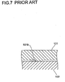
- Fig. 7 shows a cross section of the die cut along the dashed dotted line in Fig. 6
- Fig. 8 is a perspective view of the conventional rear case viewed from the open side.
- a first die 101 having a recess and a second die 102 having a salient are combined so that the recess and the salient are engaged with each other when the rear case 3 is molded.
- the recess and the salient are opposed to each other with a predetermined space between them, which forms a cavity 103.
- the rear case 3 is molded by filling a melted resin material (hereinafter referred to as a "material” simply) in the cavity 103 and curing the material.
- the material is injected into the cavity 103 through an injection 101 a that is formed to pass through the first die 101.
- the first die 101 is provided with a plurality of protrusions 101 b at positions corresponding to the plurality of engaging holes 3a of the rear case 3 (see Fig. 5 ) so as to form the engaging holes 3a.
- the injected material fills the cavity 103 and finally goes around the protrusion 101 b from its rear (the right in Fig. 6 ) to its both sides (the front and the back of paper of Fig. 6 ) so as to reach the vertical face of the second die 102, and flows of the material from both sides go to the front of the protrusion 101 b (the left in Fig. 6 ) so as to meet at the middle part.
- a so-called weld line 3b may be generated at each part where the flows of the material meet as shown in Fig. 9 because the meeting flows of the material may be cured before they are mixed completely.
- This weld line 3b is a type of defective molding that causes deterioration of strength of the resin product.
- JP-A-H6-311459 disclose assembly structures of cabinets of television receivers, but they do not disclose any structure of the cabinet as described above, in which the rear case has engaging holes with which hooks of the front case are engaged.
- An object of the present invention is to provide a cabinet of electronic equipment that can suppress an occurrence of a weld line so that the periphery of the engaging hole can be reinforced, as well as a liquid crystal television receiver having the cabinet.
- a cabinet of electronic equipment includes a box-type first case with an open side made of a resin, and a box-type second case with an open side made of a resin to be fixed to the first case by engagement.
- An open part of the second case is engaged with an open part of the first case, and a plurality of hook formed on an inner wall of the open part of the first case are engaged with a plurality of engaging holes that are formed to pass through a wall of the open part of the second case and are elongated in the direction perpendicular to an engaging direction of the first and the second cases from an outer face side of the second case, so that the first and the second cases are coupled.
- a rib that crosses the engaging hole in its short side direction is formed integrally to the second case on its inner wall.
- a die for molding the second case is provided with a groove for forming a rib, which extends over a protrusion for forming the engaging hole.
- This groove provides a channel for a material to flow when the second case is molded. Therefore, the material can flow to a point where flows of the resin go around both sides of the protrusion to the front and meet. Therefore, an occurrence of a weld line is suppressed so that deterioration of strength of the second case due to the engaging holes can be prevented.
- the rib crossing the engaging hole in its short side direction is formed integrally on the molded second case, a periphery of the engaging hole of the second case can be reinforced.
- a plurality of the ribs are provided for the engaging hole so as to be arranged in the longitudinal direction of the engaging hole.
- the periphery of the engaging hole of the second case can be reinforced more strongly.
- the electronic equipment to which the present invention is applied can be a flat display device such as a liquid crystal television receiver, for example.
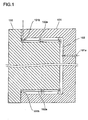
- Fig. 1 shows a vertical section of a die for molding a rear case that constitutes a cabinet of a liquid crystal television receiver according to an embodiment of the present invention
- Fig. 2 is a cross section of the die shown in Fig. 1 cut along the dashed dotted line.
- the second die 102 is provided with grooves 102a that extend over the protrusion 101 b of the first die 101 at the middle part of the protrusion 101b in its longitudinal direction (the direction perpendicular to the paper of Fig. 1 and the horizontal direction in Fig. 2 ).
- the groove 102a forms a channel in the cavity 103 for the material to flow over the protrusion 101b as shown by the arrow with the dotted line in Fig.
- the front side of the protrusion 101b where the flows of the material meet can be supplied with another flow of the material through the channel.
- an occurrence of a weld line can be suppressed so that deterioration of strength of the rear case 3 can be prevented.
- the present invention is not limited to the embodiment described above.
- the groove 102a of the second die 102 is provided only one for each of the protrusions 101 b of the first die 101 in the example shown in Figs. 1 and 2
- a plurality of ribs 3c crossing each of the engaging hole 3a in the short side direction are formed on the inner wall of the molded rear case 3.
- the periphery of the engaging hole 3a of the rear case 3 can be reinforced more strongly.
- the present invention can be applied to any cabinet of electronic equipment as long as it is constituted of first and second cases that are coupled so as to form the cabinet.
- the second case can be a detachable or pivoted lid with respect to the first case.
Landscapes
- Engineering & Computer Science (AREA)
- Multimedia (AREA)
- Signal Processing (AREA)
- Devices For Indicating Variable Information By Combining Individual Elements (AREA)
- Casings For Electric Apparatus (AREA)
Abstract
Description
- The present invention relates to a cabinet of electronic equipment (e.g., a liquid crystal television receiver), which is assembled of two open box-type cases.
- A conventional cabinet of a liquid crystal television receiver will be described as an example with reference to the attached drawings.
-
Fig. 5 is an exploded diagram of the conventional liquid crystal television receiver, in which a main circuit board and a rear case are detached to be viewed. As shown inFig. 5 , a cabinet of the liquidcrystal television receiver 1 includes a box-type front case 2 with an open rear side in which aliquid crystal module 4 and amain circuit board 5 are arranged, and a box-typerear case 3 with an open front side that is fit in the open rear part of thefront case 2 so that they are engaged with each other. An open front part of therear case 3 is formed thin to have a step on its outer face, which is engaged with the open rear part of thefront case 2. When they are engaged with each other, a plurality ofhooks 2a formed on the inner wall of the open rear part of thefront case 2 respectively engage corresponding elongated holes as a plurality of engagingholes 3 a formed in the open front part of therear case 3 to pass through its wall, so that thefront case 2 and therear case 3 are coupled to each other. - The
front case 2 is provided with asheet metal attachment 6 for attaching themain circuit board 5 to the rear side of theliquid crystal module 4 as shown inFig. 5 . Thesheet metal attachment 6 is provided with a plurality ofbackup parts 61 each of which has a threadedhole 61 a, and they are formed by cutting and raising thesheet metal attachment 6. Themain circuit board 5 is fixed to thesheet metal attachment 6 withscrews 7 that pass through a plurality ofholes 51 formed in themain circuit board 5 and are fastened to threadedholes 61 a of thebackup parts 61 of thesheet metal attachment 6. -
Fig. 6 shows a vertical section of a die for molding the conventional rear case,Fig. 7 shows a cross section of the die cut along the dashed dotted line inFig. 6 , andFig. 8 is a perspective view of the conventional rear case viewed from the open side. As shown inFigs. 6 and7 , afirst die 101 having a recess and asecond die 102 having a salient are combined so that the recess and the salient are engaged with each other when therear case 3 is molded. On this occasion, the recess and the salient are opposed to each other with a predetermined space between them, which forms acavity 103. Therear case 3 is molded by filling a melted resin material (hereinafter referred to as a "material" simply) in thecavity 103 and curing the material. The material is injected into thecavity 103 through aninjection 101 a that is formed to pass through thefirst die 101. The first die 101 is provided with a plurality ofprotrusions 101 b at positions corresponding to the plurality ofengaging holes 3a of the rear case 3 (seeFig. 5 ) so as to form theengaging holes 3a. The injected material fills thecavity 103 and finally goes around theprotrusion 101 b from its rear (the right inFig. 6 ) to its both sides (the front and the back of paper ofFig. 6 ) so as to reach the vertical face of thesecond die 102, and flows of the material from both sides go to the front of theprotrusion 101 b (the left inFig. 6 ) so as to meet at the middle part. - Therefore, when the molded
rear case 3 is viewed from the open side as shown inFig. 8 , a so-calledweld line 3b may be generated at each part where the flows of the material meet as shown inFig. 9 because the meeting flows of the material may be cured before they are mixed completely. Thisweld line 3b is a type of defective molding that causes deterioration of strength of the resin product. As a result, if thehook 2a and theengaging hole 3a are hard to catch each other when thefront case 2 and therear case 3 are coupled, a stress exerting on the periphery of theengaging hole 3a of therear case 3 may cause a crack along theweld line 3b resulting in a breakage of therear case 3. -
JP-A-H6-311459 Japanese Utility Model No. 3090702 JP-A-S64-37183 - An object of the present invention is to provide a cabinet of electronic equipment that can suppress an occurrence of a weld line so that the periphery of the engaging hole can be reinforced, as well as a liquid crystal television receiver having the cabinet.
- A cabinet of electronic equipment according to an embodiment of the present invention includes a box-type first case with an open side made of a resin, and a box-type second case with an open side made of a resin to be fixed to the first case by engagement. An open part of the second case is engaged with an open part of the first case, and a plurality of hook formed on an inner wall of the open part of the first case are engaged with a plurality of engaging holes that are formed to pass through a wall of the open part of the second case and are elongated in the direction perpendicular to an engaging direction of the first and the second cases from an outer face side of the second case, so that the first and the second cases are coupled. A rib that crosses the engaging hole in its short side direction is formed integrally to the second case on its inner wall.
- According to this structure, a die for molding the second case is provided with a groove for forming a rib, which extends over a protrusion for forming the engaging hole. This groove provides a channel for a material to flow when the second case is molded. Therefore, the material can flow to a point where flows of the resin go around both sides of the protrusion to the front and meet. Therefore, an occurrence of a weld line is suppressed so that deterioration of strength of the second case due to the engaging holes can be prevented. In addition, since the rib crossing the engaging hole in its short side direction is formed integrally on the molded second case, a periphery of the engaging hole of the second case can be reinforced.
- In addition, as to the cabinet of electronic equipment according to another embodiment of the present invention, a plurality of the ribs are provided for the engaging hole so as to be arranged in the longitudinal direction of the engaging hole.
- According to this structure, since the plurality of ribs are formed so as to be arranged in the longitudinal direction of each of the engaging holes of the rear case, the periphery of the engaging hole of the second case can be reinforced more strongly.
- The electronic equipment to which the present invention is applied can be a flat display device such as a liquid crystal television receiver, for example.
-
-
Fig. 1 shows a vertical section of a die for molding a rear case that constitutes a cabinet of a liquid crystal television receiver according to an embodiment of the present invention. -
Fig. 2 is a cross section of the die shown inFig. 1 cut along the dashed dotted line. -
Fig. 3 is a perspective view of a rear case according to the embodiment viewed from the open side. -
Fig. 4 is a magnified view of the part encircled by the broken line inFig. 3 . -
Fig. 5 is an exploded diagram of a conventional liquid crystal television receiver, in which a main circuit board and a rear case are detached to be viewed. -
Fig. 6 shows a vertical section of a die for molding the conventional rear case. -
Fig. 7 shows a cross section of the die cut along the dashed dotted line inFig. 6 . -
Fig. 8 is a perspective view of the conventional rear case viewed from the open side. -
Fig. 9 is a magnified view of the part encircled by the broken line inFig. 8 . - Hereinafter, a preferred embodiment of the present invention will be described with reference to the attached drawings. In the following description, the same parts as those of the conventional liquid crystal television receiver shown in
Figs. 5-9 are denoted by the same reference numerals so that a detailed description thereof will be omitted. -
Fig. 1 shows a vertical section of a die for molding a rear case that constitutes a cabinet of a liquid crystal television receiver according to an embodiment of the present invention, andFig. 2 is a cross section of the die shown inFig. 1 cut along the dashed dotted line. As shown inFigs. 1 and2 , thesecond die 102 is provided withgrooves 102a that extend over theprotrusion 101 b of thefirst die 101 at the middle part of theprotrusion 101b in its longitudinal direction (the direction perpendicular to the paper ofFig. 1 and the horizontal direction inFig. 2 ). Thegroove 102a forms a channel in thecavity 103 for the material to flow over theprotrusion 101b as shown by the arrow with the dotted line inFig. 1 . Therefore, the front side of theprotrusion 101b where the flows of the material meet can be supplied with another flow of the material through the channel. Thus, an occurrence of a weld line can be suppressed so that deterioration of strength of therear case 3 can be prevented. - Since the material is filled and cured also in the
groove 102a of thesecond die 102 as described above,ribs 3c crossing individualengaging holes 3a in the short side direction are formed on the inner wall of the moldedrear case 3 as shown inFigs. 3 and 4 . Thus, the periphery of theengaging hole 3 a of therear case 3 can be reinforced. Therefore, even if thehook 2a of thefront case 2 and theengaging hole 3a of therear case 3 are hard to catch each other, a breakage of therear case 3 due to shortage of strength in the periphery of theengaging hole 3a can be prevented. - The present invention is not limited to the embodiment described above. For example, although the
groove 102a of thesecond die 102 is provided only one for each of theprotrusions 101 b of thefirst die 101 in the example shown inFigs. 1 and2 , it is possible to adopt another structure in which a plurality of grooves are provided for each of theprotrusions 101b so as to be arranged in the longitudinal direction of theprotrusion 101b. According to this structure, a plurality ofribs 3c crossing each of theengaging hole 3a in the short side direction are formed on the inner wall of the moldedrear case 3. As a result, the periphery of theengaging hole 3a of therear case 3 can be reinforced more strongly. - Although the liquid crystal television receiver is exemplified in the embodiment described above, the present invention can be applied to any cabinet of electronic equipment as long as it is constituted of first and second cases that are coupled so as to form the cabinet. In this case, the second case can be a detachable or pivoted lid with respect to the first case.
Claims (3)
- A cabinet of electronic equipment, comprising:a box-type first case with an open side made of a resin: anda box-type second case with an open side made of a resin to be fixed to the first case by engagement, whereinan open part of the second case is engaged with an open part of the first case, and a plurality of hook formed on an inner wall of the open part of the first case are engaged with a plurality of engaging holes that are formed to pass through a wall of the open part of the second case and are elongated in the direction perpendicular to an engaging direction of the first and the second cases from an outer face side of the second case, so that the first and the second cases are coupled, anda rib that crosses the engaging hole in its short side direction is formed integrally to the second case on its inner wall.
- The cabinet of electronic equipment according to claim 1, wherein a plurality of the ribs are provided for the engaging hole so as to be arranged in the longitudinal direction of the engaging hole.
- The cabinet of electronic equipment according to claim 1 or claim 2, wherein the electronic equipment is a liquid crystal television receiver.
Applications Claiming Priority (1)
| Application Number | Priority Date | Filing Date | Title |
|---|---|---|---|
| JP2007015864A JP4940964B2 (en) | 2007-01-26 | 2007-01-26 | Electronic equipment casing and liquid crystal television receiver |
Publications (3)
| Publication Number | Publication Date |
|---|---|
| EP1950961A2 true EP1950961A2 (en) | 2008-07-30 |
| EP1950961A3 EP1950961A3 (en) | 2009-12-30 |
| EP1950961B1 EP1950961B1 (en) | 2013-01-02 |
Family
ID=39456573
Family Applications (1)
| Application Number | Title | Priority Date | Filing Date |
|---|---|---|---|
| EP08001452A Not-in-force EP1950961B1 (en) | 2007-01-26 | 2008-01-25 | Cabinet of electronic equipment |
Country Status (3)
| Country | Link |
|---|---|
| US (1) | US8223276B2 (en) |
| EP (1) | EP1950961B1 (en) |
| JP (1) | JP4940964B2 (en) |
Cited By (1)
| Publication number | Priority date | Publication date | Assignee | Title |
|---|---|---|---|---|
| CN111491122A (en) * | 2020-04-16 | 2020-08-04 | 深圳康佳电子科技有限公司 | Front shell assembly, television and assembling method thereof |
Families Citing this family (10)
| Publication number | Priority date | Publication date | Assignee | Title |
|---|---|---|---|---|
| JP2010068388A (en) * | 2008-09-12 | 2010-03-25 | Funai Electric Co Ltd | Cabinet of electronic equipment |
| JPWO2013031860A1 (en) * | 2011-08-31 | 2015-03-23 | 帝人株式会社 | Molded body having standing surface and method for producing the same |
| JP2013055166A (en) * | 2011-09-01 | 2013-03-21 | Toshiba Corp | Television receiver and electronic apparatus |
| USD712857S1 (en) * | 2014-04-08 | 2014-09-09 | Funai Corporation | Television frame |
| USD712860S1 (en) * | 2014-04-08 | 2014-09-09 | Funai Corporation | Television frame |
| USD712856S1 (en) * | 2014-04-08 | 2014-09-09 | Funai Corporation | Television frame |
| USD712859S1 (en) * | 2014-04-08 | 2014-09-09 | Funai Corporation | Television frame |
| USD712855S1 (en) * | 2014-04-08 | 2014-09-09 | Funai Corporation | Television frame |
| USD712858S1 (en) * | 2014-04-08 | 2014-09-09 | Funai Corporation | Television frame |
| JP7571904B1 (en) | 2024-01-31 | 2024-10-23 | 積水ハウス株式会社 | Pile construction method, pipe pile and pile structure |
Citations (3)
| Publication number | Priority date | Publication date | Assignee | Title |
|---|---|---|---|---|
| JPS6437183A (en) | 1987-07-31 | 1989-02-07 | Sony Corp | Television receiver chassis |
| JPH0390702A (en) | 1989-09-04 | 1991-04-16 | Nippon Hodo Co Ltd | Paving method |
| JPH06311459A (en) | 1993-04-27 | 1994-11-04 | Hitachi Ltd | Cabinet back cover mounting structure |
Family Cites Families (20)
| Publication number | Priority date | Publication date | Assignee | Title |
|---|---|---|---|---|
| US4685558A (en) * | 1986-04-10 | 1987-08-11 | L'oreal, S.A. | Cosmetic compact with pinless internal hinge |
| JP2508020Y2 (en) * | 1989-10-02 | 1996-08-21 | 住友ゴム工業株式会社 | Laminated rubber bearing |
| US5079799A (en) * | 1990-11-14 | 1992-01-14 | General Clutch Corporation | Friction hinge assembly |
| US5231734A (en) * | 1991-11-04 | 1993-08-03 | General Clutch Corporation | Friction hinge assembly |
| JPH06188576A (en) * | 1992-12-18 | 1994-07-08 | Mitsubishi Electric Corp | Mechanism for mounting electronic equipment |
| US5936842A (en) * | 1993-12-17 | 1999-08-10 | Robert Bosch Gmbh | Housing for electric-drive units |
| CA2185452A1 (en) * | 1994-03-18 | 1995-09-28 | Patrick Sandell | Protective cartridge for rewritable optical disk |
| TW381802U (en) * | 1998-02-23 | 2000-02-01 | Acer Peripherals Inc | Structure of monitor body with detachable mount |
| US5992681A (en) * | 1998-03-09 | 1999-11-30 | Schneider Automation, Inc. | Battery door assembly |
| US6045783A (en) * | 1998-05-22 | 2000-04-04 | Coty B.V. | Cosmetic formulation with a swelling effect |
| JP2001108973A (en) * | 1999-08-04 | 2001-04-20 | Advanced Display Inc | Liquid crystal display device and assembling method thereof |
| JP2001148578A (en) * | 1999-09-06 | 2001-05-29 | Sony Computer Entertainment Inc | Electronic equipment housing and electronic equipment |
| JP3293817B2 (en) * | 2000-05-09 | 2002-06-17 | 株式会社ソニー・コンピュータエンタテインメント | Electronic equipment housing and electronic equipment |
| JP3076330U (en) * | 2000-09-14 | 2001-03-30 | 船井電機株式会社 | cabinet |
| KR100381787B1 (en) * | 2000-12-27 | 2003-04-26 | 삼성전자주식회사 | Displaying Apparatus |
| JP3090702U (en) | 2002-06-13 | 2002-12-26 | 船井電機株式会社 | Cabinet mounting structure |
| JP3099440U (en) * | 2003-07-24 | 2004-04-08 | 船井電機株式会社 | TV cabinet |
| JP3852707B2 (en) * | 2004-07-27 | 2006-12-06 | 船井電機株式会社 | LCD module |
| JP3112212U (en) * | 2005-04-26 | 2005-08-04 | 船井電機株式会社 | Panel display television and cabinet structure |
| US20080122993A1 (en) * | 2006-11-29 | 2008-05-29 | Sanyo Electric Co., Ltd. | Television image receiver |
-
2007
- 2007-01-26 JP JP2007015864A patent/JP4940964B2/en not_active Expired - Fee Related
-
2008
- 2008-01-25 US US12/010,546 patent/US8223276B2/en not_active Expired - Fee Related
- 2008-01-25 EP EP08001452A patent/EP1950961B1/en not_active Not-in-force
Patent Citations (3)
| Publication number | Priority date | Publication date | Assignee | Title |
|---|---|---|---|---|
| JPS6437183A (en) | 1987-07-31 | 1989-02-07 | Sony Corp | Television receiver chassis |
| JPH0390702A (en) | 1989-09-04 | 1991-04-16 | Nippon Hodo Co Ltd | Paving method |
| JPH06311459A (en) | 1993-04-27 | 1994-11-04 | Hitachi Ltd | Cabinet back cover mounting structure |
Cited By (2)
| Publication number | Priority date | Publication date | Assignee | Title |
|---|---|---|---|---|
| CN111491122A (en) * | 2020-04-16 | 2020-08-04 | 深圳康佳电子科技有限公司 | Front shell assembly, television and assembling method thereof |
| CN111491122B (en) * | 2020-04-16 | 2022-07-22 | 深圳康佳电子科技有限公司 | Front shell assembly, television and assembling method thereof |
Also Published As
| Publication number | Publication date |
|---|---|
| US20080180002A1 (en) | 2008-07-31 |
| JP2008182622A (en) | 2008-08-07 |
| US8223276B2 (en) | 2012-07-17 |
| JP4940964B2 (en) | 2012-05-30 |
| EP1950961A3 (en) | 2009-12-30 |
| EP1950961B1 (en) | 2013-01-02 |
Similar Documents
| Publication | Publication Date | Title |
|---|---|---|
| EP1950961B1 (en) | Cabinet of electronic equipment | |
| US8665391B2 (en) | Liquid crystal display device and its case | |
| US7627973B2 (en) | Frame structure adapted to different display panel thicknesses and corresponding engaging device | |
| EP1998564A2 (en) | Cabinet | |
| US7658456B2 (en) | Television and rib structure | |
| CN1763347B (en) | Door | |
| US8678604B2 (en) | Mold for back frame and bracing piece, method for manufacturing back frame, and backlight system | |
| US20130128535A1 (en) | Back Frame, Mold for Back Frame and Bracing Piece, Method for Manufacturing Back Frame, and Backlight System | |
| CN210274759U (en) | Casing draw gluey structure, casing and electronic equipment | |
| US8545038B2 (en) | Back frame of flat panel display device, backlight system, and flat liquid crystal display device | |
| US20130128514A1 (en) | Mold for Back Frame and Bracing Piece, Method for Manufacturing Back Frame, and Backlight System | |
| US20130128499A1 (en) | Back Frame, Mold For Back Frame, Method For Manufacturing Back Frame, and Backlight System | |
| US8804373B2 (en) | Back frame and backlight system of flat panel display device | |
| US20130128524A1 (en) | Back Frame and Backlight System Thereof | |
| US7467832B2 (en) | Cabinet for television set | |
| US9036107B2 (en) | Flat panel display device, stereoscopic display device, plasma display device | |
| US8960985B2 (en) | Back frame, method for manufacturing back frame, and backlight system | |
| JP4325347B2 (en) | Electronic device display housing | |
| CN206993560U (en) | Spacing subassembly and display device of circuit board | |
| US7854484B2 (en) | Television receiving set | |
| JP5367124B2 (en) | Display device and television receiver | |
| EP1928173B1 (en) | Television and rib structure | |
| JP4595970B2 (en) | Television equipment | |
| KR100617191B1 (en) | Cabinet and back cover integrated monitor case with concealed slide coupling structure | |
| US8872995B2 (en) | Flat panel display device, stereoscopic display device, and plasma display device |
Legal Events
| Date | Code | Title | Description |
|---|---|---|---|
| PUAI | Public reference made under article 153(3) epc to a published international application that has entered the european phase |
Free format text: ORIGINAL CODE: 0009012 |
|
| AK | Designated contracting states |
Kind code of ref document: A2 Designated state(s): AT BE BG CH CY CZ DE DK EE ES FI FR GB GR HR HU IE IS IT LI LT LU LV MC MT NL NO PL PT RO SE SI SK TR |
|
| AX | Request for extension of the european patent |
Extension state: AL BA MK RS |
|
| PUAL | Search report despatched |
Free format text: ORIGINAL CODE: 0009013 |
|
| AK | Designated contracting states |
Kind code of ref document: A3 Designated state(s): AT BE BG CH CY CZ DE DK EE ES FI FR GB GR HR HU IE IS IT LI LT LU LV MC MT NL NO PL PT RO SE SI SK TR |
|
| AX | Request for extension of the european patent |
Extension state: AL BA MK RS |
|
| 17P | Request for examination filed |
Effective date: 20100215 |
|
| AKX | Designation fees paid |
Designated state(s): DE FR GB |
|
| GRAP | Despatch of communication of intention to grant a patent |
Free format text: ORIGINAL CODE: EPIDOSNIGR1 |
|
| GRAS | Grant fee paid |
Free format text: ORIGINAL CODE: EPIDOSNIGR3 |
|
| GRAA | (expected) grant |
Free format text: ORIGINAL CODE: 0009210 |
|
| AK | Designated contracting states |
Kind code of ref document: B1 Designated state(s): DE FR GB |
|
| REG | Reference to a national code |
Ref country code: GB Ref legal event code: FG4D |
|
| REG | Reference to a national code |
Ref country code: DE Ref legal event code: R096 Ref document number: 602008021255 Country of ref document: DE Effective date: 20130307 |
|
| PLBE | No opposition filed within time limit |
Free format text: ORIGINAL CODE: 0009261 |
|
| STAA | Information on the status of an ep patent application or granted ep patent |
Free format text: STATUS: NO OPPOSITION FILED WITHIN TIME LIMIT |
|
| 26N | No opposition filed |
Effective date: 20131003 |
|
| REG | Reference to a national code |
Ref country code: DE Ref legal event code: R097 Ref document number: 602008021255 Country of ref document: DE Effective date: 20131003 |
|
| REG | Reference to a national code |
Ref country code: FR Ref legal event code: PLFP Year of fee payment: 9 |
|
| PGFP | Annual fee paid to national office [announced via postgrant information from national office to epo] |
Ref country code: FR Payment date: 20151208 Year of fee payment: 9 |
|
| PGFP | Annual fee paid to national office [announced via postgrant information from national office to epo] |
Ref country code: GB Payment date: 20160120 Year of fee payment: 9 |
|
| PGFP | Annual fee paid to national office [announced via postgrant information from national office to epo] |
Ref country code: DE Payment date: 20170117 Year of fee payment: 10 |
|
| REG | Reference to a national code |
Ref country code: DE Ref legal event code: R084 Ref document number: 602008021255 Country of ref document: DE |
|
| GBPC | Gb: european patent ceased through non-payment of renewal fee |
Effective date: 20170125 |
|
| REG | Reference to a national code |
Ref country code: FR Ref legal event code: ST Effective date: 20170929 |
|
| PG25 | Lapsed in a contracting state [announced via postgrant information from national office to epo] |
Ref country code: FR Free format text: LAPSE BECAUSE OF NON-PAYMENT OF DUE FEES Effective date: 20170131 |
|
| PG25 | Lapsed in a contracting state [announced via postgrant information from national office to epo] |
Ref country code: GB Free format text: LAPSE BECAUSE OF NON-PAYMENT OF DUE FEES Effective date: 20170125 |
|
| REG | Reference to a national code |
Ref country code: DE Ref legal event code: R119 Ref document number: 602008021255 Country of ref document: DE |
|
| PG25 | Lapsed in a contracting state [announced via postgrant information from national office to epo] |
Ref country code: DE Free format text: LAPSE BECAUSE OF NON-PAYMENT OF DUE FEES Effective date: 20180801 |