EP1950788A1 - X-ray tube and x-ray source including same - Google Patents
X-ray tube and x-ray source including same Download PDFInfo
- Publication number
- EP1950788A1 EP1950788A1 EP06811125A EP06811125A EP1950788A1 EP 1950788 A1 EP1950788 A1 EP 1950788A1 EP 06811125 A EP06811125 A EP 06811125A EP 06811125 A EP06811125 A EP 06811125A EP 1950788 A1 EP1950788 A1 EP 1950788A1
- Authority
- EP
- European Patent Office
- Prior art keywords
- anode
- ray tube
- tip
- wall surface
- ray
- Prior art date
- Legal status (The legal status is an assumption and is not a legal conclusion. Google has not performed a legal analysis and makes no representation as to the accuracy of the status listed.)
- Granted
Links
Images








Classifications
-
- H—ELECTRICITY
- H01—ELECTRIC ELEMENTS
- H01J—ELECTRIC DISCHARGE TUBES OR DISCHARGE LAMPS
- H01J35/00—X-ray tubes
- H01J35/02—Details
- H01J35/16—Vessels; Containers; Shields associated therewith
-
- H—ELECTRICITY
- H01—ELECTRIC ELEMENTS
- H01J—ELECTRIC DISCHARGE TUBES OR DISCHARGE LAMPS
- H01J35/00—X-ray tubes
- H01J35/02—Details
-
- H—ELECTRICITY
- H01—ELECTRIC ELEMENTS
- H01J—ELECTRIC DISCHARGE TUBES OR DISCHARGE LAMPS
- H01J35/00—X-ray tubes
- H01J35/02—Details
- H01J35/025—X-ray tubes with structurally associated circuit elements
-
- H—ELECTRICITY
- H01—ELECTRIC ELEMENTS
- H01J—ELECTRIC DISCHARGE TUBES OR DISCHARGE LAMPS
- H01J35/00—X-ray tubes
- H01J35/02—Details
- H01J35/04—Electrodes ; Mutual position thereof; Constructional adaptations therefor
- H01J35/08—Anodes; Anti cathodes
- H01J35/112—Non-rotating anodes
-
- H—ELECTRICITY
- H05—ELECTRIC TECHNIQUES NOT OTHERWISE PROVIDED FOR
- H05G—X-RAY TECHNIQUE
- H05G1/00—X-ray apparatus involving X-ray tubes; Circuits therefor
- H05G1/02—Constructional details
- H05G1/04—Mounting the X-ray tube within a closed housing
- H05G1/06—X-ray tube and at least part of the power supply apparatus being mounted within the same housing
Definitions
- the present invention relates to an X-ray tube taking out X-rays generated wherein toward an exterior, and an X-ray source in which the X-ray tube and a power supply unit are configured integrally.
- X-rays are electromagnetic waves that are highly transmitted through objects and are frequently used for nondestructive, noncontact observation of internal structures of objects.
- an X-ray tube described in Patent Document 1 indicated below.
- An X-ray generating unit of the X-ray tube described in Patent Document 1 has a tubular casing that houses a target, and an exhaust pipe, put in communication with an internal space, is mounted to the casing (see Fig. 4 , etc., of Patent Document 1).
- vacuum is drawn from the internal space of the casing via the exhaust pipe. After vacuum drawing, the exhaust pipe is closed and the internal space that houses the target is put in a vacuum state (state of being depressurized to a predetermined degree of vacuum).
- Patent Document 1 U. S. Patent No. 6229876
- the present inventors have examined the conventional X-ray tubes, and as a result, have discovered the following problems. That is, in the conventional X-ray tube, the exhaust port for drawing vacuum is formed in an inner wall surface of the casing onto which the exhaust pipe is mounted, and at an edge of the exhaust port, a corner portion with a sharp tip is present at a boundary with the casing inner wall.
- a high potential difference is generated across the casing and an anode during driving of the X-ray tube, an electric field across the casing and the anode may become disrupted due to an influence of the corner portion.
- a possibility of discharge occurring across the casing and a tip of the anode thus increases due to the presence of the corner portion that is inevitably formed due to forming of the exhaust port.
- no measures are taken to suppress such discharge and there was a possibility of destabilization of the X-ray output due to such discharge.
- the present invention has been developed to eliminate the problems described above. It is an object of the present invention to provide an X-ray tube having a structure for effectively suppressing discharge at a tip of an anode that is irradiated with electrons to generate X-rays, and to provide an X-ray source including the X-ray tube.
- An X-ray tube irradiates X-rays generated at an X-ray target to an exterior by making electrons emitted from an electron gun be incident on the X-ray target of an anode.
- the X-ray tube comprises a casing, an irradiation window (X-ray emission window) disposed on the casing; an exhaust port, and a shielding structure.
- the casing defines an internal space housing a tip of the anode that is irradiated with electrons.
- the irradiation window is disposed on the casing defining the internal space, in order to take out the X-rays generated at the X-ray target to the exterior of the casing.
- the exhaust port is prepared for vacuum drawing of the internal space and is disposed at an inner wall surface of the casing.
- the shielding structure is disposed in the internal space of the casing so as to hide the exhaust port from the tip of the anode.
- the shielding structure preferably includes a shielding member comprised of a conductive material and having an inner side surface that faces the tip of the anode, and an outer side surface opposing the inner side surface.
- the exhaust port is disposed at the inner wall surface of the casing.
- a corner portion with a sharp tip is thus formed as a boundary between an edge of the exhaust port and the inner wall surface of the casing.
- the present X-ray tube is thus provided with a structure, with which the exhaust port is hidden from the tip of the anode by the shielding member.
- the shielding member is preferably disposed between the tip of the anode and the exhaust port in a state of being separated by a predetermined distance from the inner wall surface at the exhaust port side of the casing.
- at least the inner side surface of the shielding member that faces the tip of the anode preferably has an area larger than an opening area of the exhaust port.
- the edge of the exhaust port (the corner portion with the sharp tip) can be covered reliably.
- vacuuming of the internal space can be performed using a gap between the shielding member and the inner wall surface at the exhaust port side as a passage for air.
- the shielding member may also be disposed in the internal space in a state of being separated by a predetermined distance from an inner wall surface at the irradiation window side of the casing.
- vacuuming of the internal space can be performed using a gap between the shielding member and the inner wall surface at the irradiation window side as a passage for air.
- the shielding member may be provided with a plurality of through holes each communicating between the inner side surface facing the tip of the anode and the outer side surface opposing the inner side surface.
- the through holes serve as passages for air from the internal space and vacuum drawing can thus be performed efficiently.
- the shielding member may be a part of the casing that extends from an inner wall surface of the casing to the internal space.
- the inner side surface of the shielding member that opposes the tip of the anode is matched with the inner wall surface of the portion of the casing.
- the surface of the shielding member and the inner wall surface of the casing can be made smoothly continuous with respect to each other. Disruption of the electric field is thus alleviated and the discharge at the tip of the anode can be suppressed further.
- the shielding member may have a plurality of through holes each putting the inner side surface and the outer side surface in communication, and be disposed so that the inner side surface facing the tip of the anode is matched with the inner wall surface of the casing.
- the shielding member is required to have the plurality of through holes that serve as passages for air during vacuum drawing.
- the shielding member that closes the exhaust port is formed flush to the inner wall surface of the casing at which the exhaust port is formed, a corner portion with a sharp tip does not appear at the edge of the exhaust port and disruption of the electric field across the tip of the anode and the exhaust port is alleviated. As a result, the discharge at the tip of the anode is suppressed effectively. Because the plurality of communicating holes formed in the shielding member serve as passages for air, vacuum drawing of the internal space during manufacture can also be carried out without any problem.
- the shielding structure may be realized according to a second aspect that differs from the first aspect described above.
- the casing may be constituted of a first anode housing portion and a second anode housing portion, and an inner tubular member may be disposed as the shielding structure in the internal space of the casing.
- the first anode housing portion is a hollow member comprised of a conductive material, the first anode housing portion surrounding the tip of the anode that has the exhaust port disposed at an inner wall surface thereof and having the irradiation window.
- the second anode housing portion defines an internal space for housing the anode together with the first anode housing portion, by being joined to the first anode housing portion.
- the inner tubular member that is the shielding structure of the second mode is a hollow member disposed in the internal space of the casing so as to surround at least the tip of the anode and, by a part thereof being positioned between the inner wall surface of the first anode housing portion and the tip of the anode in a state of being separated by a predetermined distance from the inner wall surface of the first anode housing portion, functions to hide the exhaust port from the tip of the anode.
- the exhaust port disposed at the inner wall surface of the first anode housing portion, is hidden from the tip of the anode by the inner tubular member, at least a part of which is positioned between the tip of the anode and the inner wall surface of the first anode housing portion.
- vacuuming of the internal space can be performed using a gap between the inner tubular member and the inner wall surface of the first anode housing portion as a passage for air.
- a gap is preferably formed between an end of the inner tubular member and an inner wall surface at the irradiation window side of the first anode housing portion.
- vacuum drawing of the internal space can be performed using the gap between the inner tubular member and the inner wall surface at the irradiation window side of the first anode housing portion as a passage for air.
- the inner tubular member preferably has a plurality of through holes disposed at least at a part positioned between the inner wall surface of the first anode housing portion and the tip of the anode.
- the through holes themselves serve as passages for air from the internal space during vacuum drawing of the internal space during manufacture, the vacuum drawing can be performed efficiently.
- the first anode housing portion preferably has a head comprised of a conductive material
- the second anode housing portion having a bulb comprised of an electrically insulating material and a connecting portion comprised of a conductive material, the connecting portion being joined to an end of the bulb and to the head of the first anode housing portion.
- the inner tubular member has a shape that extends toward the second anode housing portion side in the internal space so as to hide a joined portion of the bulb and the connecting portion from the anode.
- this X-ray tube discharge occurs comparatively readily across the anode and the joined portion of the bulb comprised of the electrically insulating material, and the connecting portion comprised of the conductive material.
- the joined portion is hidden from the anode by employment of the inner tubular member with the above-described structure. Disruption of the electric field across the joined portion and the anode is thus alleviated and the discharge across the joined portion and the anode is suppressed effectively. As a result, destabilization of the X-ray output of the X-ray tube is suppressed.
- the second anode housing portion preferably has a bulb comprised of an electrically insulating material
- the first anode housing portion has a head comprised of a conductive material, and a connecting portion comprised of a conductive material, the connecting portion being disposed at an end of the head and joined to the bulb of the second anode housing portion.
- the inner tubular member preferably has a shape that extends toward the second anode housing portion side in the internal space so as to hide a joined portion of the bulb and the connecting portion from the anode.
- the inner tubular member may have a loopback portion, at which an end at the second anode housing portion side is looped back into a round shape.
- a tip of the loopback portion is joined to the first anode housing portion and a through hole is formed in the loopback portion.
- the second anode housing portion side end of the inner tubular member has the round shape, a corner portion with a sharp tip is not formed. Disruption of the electric field across the end and the anode is thus suppressed effectively. As a result, discharge across the end and the anode is suppressed and destabilization of the X-ray output of the X-ray tube can be suppressed.
- a space is formed in a region surrounded by the looped back inner tubular member and the first anode housing portion.
- the through hole formed in the loopback portion serves as a passage for air during vacuum drawing of the internal space in the manufacture of the X-ray tube, retention of air in this space is prevented.
- an X-ray source comprises the X-ray tube with the above-described structure (X-ray tube according to the present invention), and a power supply unit supplying a voltage for generating X-rays at the X-ray target toward the anode at which the X-ray target is disposed.
- loopback portion 31e ... free end of loopback portion; 31f ... through hole; 31k ... communicating hole; 58 ... inner wall surface; 61a, 63a ... shielding member surface; 63f, 65f ... communicating hole; R ... internal space; d1, d2, d3, d4, S1, S2 ... gap; 100 ... X-ray source; 102 ... power supply unit; 102A ... insulating block; 102B ... high voltage generating unit; 102C ... high voltage line; 102D ... socket; 103 ... first plate member; 103A ... screw insertion hole; 104 ... second plate member; 104A ... screw insertion hole; 105 ...
- fastening spacer member 150A ... screw hole; 106 ... metal tubular member; 106A ... mounting flange; 106B ... relief surface; 106C ... insertion hole; 108 ... conductive coating; 109 ... fastening screw; 110 ... high voltage insulation oil; XC ... X-ray camera; SP ... sample plate; P ... observation point; and XP ... X-ray generation point.
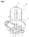
- Fig. 1 is a perspective view of an arrangement of the first embodiment of the X-ray tube according to the present invention.
- Fig. 2 is a vertical sectional view of the X-ray tube according to the first embodiment shown in Fig. 1 .
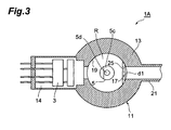
- Fig. 3 is a horizontal sectional view of the X-ray tube according to the first embodiment shown in Fig. 1 .
- the X-ray tube 1A makes electrons, emitted from an electron gun 3, be incident on a target 5d, which is an electron incidence portion (X-ray generating portion) disposed at a tip 5a of an anode 5 in vacuum, and irradiates X-rays, generated as a result of the incidence of electrons, to an exterior.
- the X-ray tube 1A includes a glass bulb 9, holding the rod-like anode 5 in an insulated state, and an X-ray generating unit 11, housing the anode tip 5a and generating X-rays.
- the X-ray generating unit 11 has a head 13, which is a metal casing that houses the anode tip 5a, and substantially the entirety of the anode 5 is housed in a sealed internal space R, defined by the head 13 and the bulb 9, in a state of being insulated from the head 13.
- An inclined surface 5c is disposed at an end surface of the anode tip 5a, and on the inclined surface 5c is disposed the target 5d that generates X-rays with a desired energy upon the incidence of electrons.
- the anode tip 5a is surrounded by an inner wall surface 19 of the head 13 forming a cylindrical surface coaxial to the anode 5.
- the electron gun 3 is housed in an electron gun housing unit 14, mounted onto the head 13, and a tip of the electron gun 3 is directed toward the anode tip 5a. That is, an axial line of the electron gun 3 and an axial line of the anode 5 are made substantially orthogonal to each other so that the electrons emitted from the electron gun 3 are made incident on the target 5d on the inclined surface 5c, formed so as to face the electron gun 3.
- a circular irradiation window 15 (X-ray emitting window) comprised of a material of high X-ray transmittance for transmitting the X-rays generated at the target 5d and thereby irradiating the X-rays to the exterior.
- an exhaust port 17, for evacuating air inside the internal space R is disposed at the inner wall surface 19 of the head 13.
- an exhaust tube 21, put in communication with the internal space R via the exhaust port 17, is mounted on an outer wall surface of the head 13.
- a base end 5b (high voltage application portion) of the anode 5, exposed from the bulb 9, is connected to a high voltage supply circuit.
- a high voltage of approximately 100kV is applied from the high voltage supply circuit to the anode 5 via the base end 5b.
- a special shielding structure (first mode) is employed. That is, a partitioning-screen-like shielding member 25, hiding the exhaust port 17 from the anode tip 5a, is disposed between the anode tip 5a and the exhaust port 17.
- the shielding member 25 is a flat plate member comprised of a conductive material, the shielding member 25 being processed to a rectangular shape and having an area larger than an open aperture of the exhaust port 17.
- the shielding member 25 has two opposing sides fixed to the inner wall surface 19 and is disposed so as to cover the exhaust port 17 across a gap d1 from the inner wall surface 19 at a central portion.
- the shielding member 25 extends very close to an inner wall surface 29, on which the irradiation window 15 is disposed, so that a small gap d2 is formed between the shielding member 25 and the inner wall surface 29. By the shielding member 25, the edge of the exhaust port 17 is prevented from being viewed from the anode tip 5a.
- the shielding member 25 In the X-ray tube 1A, by such a shielding member 25 being disposed, disruption of the electric field across the anode tip 5a and the edge of the exhaust port 17 is alleviated. Discharge across the anode tip 5a and the edge of the exhaust port 17 is thus suppressed. Also, by the gaps d1 and d2, an interior of the exhaust tube 21 and the internal space R are put in communication, and because the gaps d1 and d2 function as passages for air, vacuum drawing of the internal space R via the exhaust port 17 can be performed without any problem during manufacture. Although vacuum drawing will take some time, the shielding member 25 may be disposed so that the gap d2 is not formed. In this case, vacuum drawing can be performed using just the gap d1 as a passage for air.
- the shielding member 25 is not limited to being a flat plate member and may be a curved plate member with a curvature larger than that of the inner wall surface of the head 13.
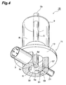
- Fig. 4 is a perspective view of an arrangement of the first modification example of the X-ray tube according to the first embodiment.
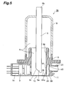
- Fig. 5 is a sectional view of the X-ray tube 1B shown in Fig. 4 .
- the X-ray tube 1B differs from the X-ray tube 1 A of the first embodiment in a shielding member structure that hides an exhaust port 57 from the anode tip 5a.
- the exhaust port 57 is positioned at an inner wall surface 59 formed by digging into a part of an inner wall surface 58 in a direction of an outer wall surface of the head 13.
- a shielding member 61 for hiding the exhaust port 57 from the anode tip 5a is disposed between the exhaust port 57 and the anode tip 5a.
- the shielding member 61 has an inner side surface 61a, facing the anode tip 5a and being matched with the inner wall surface 58 (and being practically a part of the head 13 in the present modification example), and has a rectangular shape with an area larger than the open aperture of the exhaust port 57.
- the shielding member 61 is disposed so that a gap d3 is formed across from the exhaust port 57.
- the shielding member 61 extends very close to an inner wall surface 29, on which the irradiation window 15 is disposed, so that a small gap d4 is formed between the shielding member 61 and the inner wall surface 29.
- the shielding member 61 and the exhaust port 57 with the above-described structure is prepared by carving out a region of rectangular parallelepiped shape sandwiched between the shielding member 61 and the inner wall surface 59 in the head 13 while leaving the shielding member 61 and thereafter forming the exhaust port 57 and the gap d4.
- the inner wall surface 59 may be formed by digging into the inner wall surface 58 and, after forming the exhaust port 57 in the inner wall surface 59, installing the shielding member 61 as a separate member so that its inner side surface is matched with the inner wall surface 58.
- the inner side surface 61a of shielding member 61 being matched with the inner wall surface 58 that surrounds the anode tip 5a, the inner side surface 61 a of the shielding member 61 is made smoothly continuous with the inner wall surface 58. In this configuration, disruption of the electric field around the target tip 5a due to the shielding member 61 can thus be minimized.
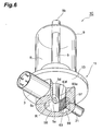
- Fig. 6 is a perspective view of an arrangement of the second modification example of the X-ray tube according to the first embodiment.
- Fig. 7 is a sectional view of the X-ray tube 1C shown in Fig. 6 .
- the X-ray tube 1C differs from the X-ray tube 1B of the second embodiment in a structure of a shielding member 63.
- the shielding member 63 is a mesh-like conductive member provided with a plurality of through holes 63 f and has the same shape as the above-described shielding member 61.
- the shielding member 63 is formed so that an inner side surface 63a, facing the anode tip 5a, is matched with the inner wall surface 58 that surrounds the anode tip 5a.
- the shielding member 63 by making the through holes 63f fine, disruption of the electric field across the anode tip 5a and the edge of the exhaust port 57 is alleviated in similar to the shielding member 61 in the X-ray tube 1B. Discharge across the anode tip 5a and the edge of the exhaust port 57 can thus be suppressed effectively with the X-ray tube 1C as well. Because in the process of vacuum drawing of the internal space R during manufacture not only the gaps d3 and d4 but the through holes 63f also function as passages for air, smooth vacuum drawing is enabled. As a hole diameter of the through holes 63f, 0.1 to 1mm is preferable for alleviating the disruption of the electrical field and performing smooth vacuum drawing.
- FIG. 8 is a perspective view of an arrangement of the third modification example of the X-ray tube according to the first embodiment.
- Fig. 9 is a sectional view of the X-ray tube 1D shown in Fig. 8 .
- the X-ray tube 1D differs from the X-ray tube 1 A of the first embodiment in a structure of a shielding member that hides the exhaust port 17 from the anode tip 5a.
- the shielding member 65 is a mesh-like conductive member, provided with a plurality of through holes 65f and disposed so as to close the exhaust port 17 while an inner side surface, facing the anode 5, is matched with the inner wall surface 19.
- the shielding member 65 because an end portion does not appear at the inner wall surface 19 at the edge of the exhaust port 17, disruption of the electric field across the anode tip 5a and the edge of the exhaust port 57 is alleviated. Discharge across the anode tip 5a and the edge of the exhaust port 17 can thus be suppressed. Also, the interior of the exhaust tube 21 and the internal space R are put in communication by the plurality of through holes 65f, provided in the shielding member 65, and the through holes 65f function as passages for air. Vacuum drawing of the internal space R via the exhaust port 17 can thus be performed without any problem during manufacture. As a hole diameter of the through holes 65f, 0.1 to 1mm is preferable for alleviating the disruption of the electrical field and performing smooth vacuum drawing.
- the present invention is not restricted to the above-described first embodiment and modification examples thereof and can be modified variously.
- the target 5d is disposed as a separate member on the inclined surface 5c of the anode 5
- the anode 5 and the target 5d can be configured integrally so that a part of the inclined surface 5c constitutes the target.
- the anode 5 has a shape having the inclined surface 5c disposed at the tip of a cylindrical column, other shapes can be provided at the tip of the anode 5 by any of various types of carving. In this case, even if a corner-like portion is present at the tip of the anode, discharge across the anode tip and the exhaust port can be suppressed effectively by the shielding member.
- Fig. 10 is a perspective view of the arrangement of the second embodiment of the X-ray tube according to the present invention.
- Fig. 11 is an exploded perspective view of the X-ray tube 2A according to the second embodiment shown in Fig. 10 .
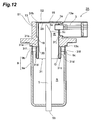
- Fig. 12 is a sectional view of the X-ray tube 2A according to the second embodiment shown in Fig. 10 .
- Fig. 13 is a sectional view taken across a central axis of an exhaust tube of the X-ray tube 2A according to the second embodiment shown in Fig. 10 .
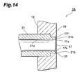
- Fig. 14 is a sectional view of a vicinity of a mounting portion of the exhaust tube of the X-ray tube 2A according to the second embodiment shown in Fig. 10 .
- the X-ray tube 2A makes electrons, emitted from the electron gun 3, be incident on the target 5d, which is the electron incidence portion (X-ray generating portion) disposed at the tip 5a of the anode 5 in vacuum, and irradiates X-rays, generated as the result of the incidence of electrons, to the exterior.
- the X-ray tube 2A includes a body portion (second anode housing portion) 9, holding the rod-like anode 5 in an insulated state, and the head (first anode housing portion) 13, which is the metal casing that surrounds the anode tip 5a.
- the body portion 9 is constituted of a bulb 9a comprised of glass, which is an electrically insulating material, and a connecting portion 9b connecting the bulb 9a and the head 13.
- a bulb 9a comprised of glass, which is an electrically insulating material
- a connecting portion 9b connecting the bulb 9a and the head 13.
- One end side of the bulb 9a is open and the other end side holds the anode 5.
- one end of the cylindrical connecting portion 9b which is comprised of metal, is joined by fusing.
- An outwardly extending flange is disposed at the other end of the connecting portion 9b, and the connecting portion 9b is welded to the head 13 at this flange. That is, the bulb 9a and the head 13 are connected via the connecting portion 9b.
- Substantially the entirety of the anode 5 is housed inside the internal space R in a state of being insulated from the head 13 and the connecting portion 9b.
- the inclined surface 5c is disposed at the anode tip 5a, and on the inclined surface 5c is disposed the target 5d that generates the X-rays with the desired energy upon the incidence of electrons.
- the first anode housing portion may be configured by integrally disposing the tubular connecting portion 9b, for fusing with the bulb 9a, at an end of the head 13.
- the bulb 9a constitutes the second anode housing portion.
- the head 13 has inner wall surfaces 19 and 20, constituting cylindrical surfaces coaxial to the anode 5, and the anode tip 5a is surrounded by the inner wall surfaces 19 and 20.
- the electron gun housing unit 14, housing the electron gun 3, is mounted to a mounting hole 13a, formed so as to penetrate through a side wall of the head 13.
- the electron gun 3 is positioned while the axial line of the electron gun 3 and the axial line of the anode 5 are made substantially orthogonal to each other. That is, the tip of the electron gun 3 is directed toward the anode tip 5a so that the electrons emitted from the electron gun 3 are made incident on the target 5d on the inclined surface 5c, formed so as to face the electron gun 3.
- the circular irradiation window 15 (X-ray emitting window) comprised of a material of high X-ray transmittance for transmitting the X-rays generated at the target 5d and thereby irradiating the X-rays to the exterior.
- the exhaust port 17, for evacuating air inside the internal space R is disposed at the inner wall surface 19 of the head 13. Furthermore, the exhaust tube 21, put in communication with the internal space R via the exhaust port 17, is mounted on the outer wall surface of the head 13.
- the exhaust port 17 is left open to the internal space R even after completion of assembly of the X-ray tube.
- the exhaust port 17 is formed at an inner wall surface 19 position diagonally in front of the mounting hole 13a, the exhaust port 17 may be formed at any position of the inner wall surface 19 or 20.
- the base end 5b (high voltage application portion) of the anode 5, exposed from the bulb 9, is connected to the high voltage supply circuit.
- the high voltage of approximately 100kV is applied from the high voltage supply circuit to the anode 5, including the target 5d, via the base end 5b.
- the electrons emitted from the electron gun 3 in this state become incident on the target 5d, X-rays are generated from the target 5d by the incidence of electrons.
- the generated X-rays are transmitted through the irradiation window 15 and irradiated to the exterior.
- the terms, "upper,” “lower,” etc. are used with the irradiation window 15 side being the upper side and the base end 5b side of the anode 5 being the lower side in the description of the second embodiment as well.
- anode tip 5a is housed so as to be surrounded by the head 13. There is thus a problem of discharge occurring across the anode tip 5a and the inner wall surface 19 of the head 13.
- an abrupt corner portion 17e appears at a boundary between an inner wall surface 21a of the exhaust tube 21 and an end surface 21b of the exhaust tube 21 and an abrupt corner portion 17f appears at a boundary between the exhaust port 17 and the inner wall surface 19.
- a special shielding structure (second mode) is employed. That is, an inner tubular member 31 is disposed between the inner wall surface 19 of the head 13 and the anode tip 5a.
- the inner tubular member 31 is a conductive member comprised of metal and has a thickness thinner than the head 31, the inner tubular member 31 having a cylindrical shape that surrounds the anode tip 5a.
- an outer diameter of the inner tubular member 31 is set substantially equal to an inner diameter of the head 13 at the inner wall surface 20.
- the cylindrical portion 31 is disposed so as to be coaxial to the anode 5 and the inner wall surface 19 of the head 13.
- a small gap S 1 is formed between the outer wall surface 31 a of the inner tubular member 31 and the inner wall surface 19 of the head 13.
- the inner tubular member 31 extends very close to the inner wall surface 29, on which the irradiation window 15 is disposed, so that a small gap S2 is formed between an upper end 31b of the inner tubular member 31 and the inner wall surface 29.
- the internal space R is put in communication with the interior of the exhaust tube 21 via the gaps S 1 and S2, and in the process of vacuum drawing of the internal space R, the gaps S 1 and S2 function as passages for air.
- a lower end 31c side of the inner tubular member 31 protrudes from a lower end of the head 13 and extends below a fused portion (joined portion) 9c of the bulb 9a and the connecting portion 9b.
- the inner tubular member 31 is made present between the fused portion 9c and the target 5.
- the fused portion 9c is thus hidden from view from the anode 5 by the inner tubular member 31.
- the lower end 31 c of the inner tubular member 31 is looped back into a round shape with a curved surface and a free end 31e of a loopback portion 31d facing the bulb 9a side is joined by brazing to a lower end surface 13 c of the head 13.
- an insertion hole 31h is formed at a position corresponding to the electron gun 3, and a tip 3a of a housing container that houses the electron gun 3 is inserted into the insertion hole 31h and becomes exposed at the anode tip 5a side.
- a pair of flat portions 31p, parallel to the axial line of the electron gun 3, are formed on the inner tubular member 31.
- the flat portions 31p are positioned symmetrically so as to sandwich the insertion hole 31h in between and have shapes that bulge toward the anode tip 5a side from an inner wall surface 31j.
- the flat portions 31p function as electrodes for putting the electric field, via which the electrons emitted from the electron gun 3 reach the target 5d, into a desired state.
- the gaps S 1 and S2 the interior of the exhaust tube 21 and the internal space R are put in communication, and because the gaps S1 and S2 function as passages for air, vacuum drawing of the internal space R via the exhaust port 17 can be performed without any problem during manufacture of the X-ray tube 2A.
- rear sides of the flat portions 31p are processed to shapes that are recessed from the outer wall surface 31a.
- a comparatively wide space corresponding to the amount of recess from the outer wall surface 31a,is formed between the inner wall surface 19 of the head 13 and the rear side of each flat portion 31p. Because the exhaust port 17 is positioned in the comparatively wide space between the inner wall surface 19 and the rear side of one of the flat portions 31p so as to face the rear side of the flat portion 31p, the passage of air is made good by the space and vacuum drawing of the internal space R via the exhaust port 17 during manufacture of the X-ray tube 2A is thereby facilitated.
- positioning in a direction of extension of the anode 5 is enabled by contacting of the tip 31e of the loopback portion with the lower end surface 13c of the head 13.
- the positioning in a surface orthogonal to the direction of extension of the anode 5 is performed by making the outer wall surface 31a of the inner tubular member 31 contact the inner wall surface 20 of the head 13.
- the inner tubular member 31 is a separate member from the head 13, and because the inner tubular member 31 can be prepared independently, the inner wall surface 31j that is smooth and high in precision is obtained. That is, because in comparison to directly subjecting the head 13 to processing for hiding the exhaust port 17 from the anode tip 5a, it is easier to smoothen the inner wall surface 31j that faces the anode tip 5a, the discharge across the anode tip 5a and the inner tubular member 31 can be suppressed effectively.
- the discharge at the anode 5 can be suppressed effectively, destabilization of the X-ray output due to the discharge is suppressed (stable X-ray irradiation can be performed).
- Fig. 15 is a sectional view of an arrangement of the first modification example of the X-ray tube according to the second embodiment.
- the X-ray tube 2B (first modification example of the X-ray tube according to the second embodiment) has an inner tubular member 33 in place of the inner tubular member 31 of the X-ray tube 2A.
- a part that protrudes below the lower end surface 13c of the head 13 extends below the fused portion 9c of the bulb 9a and the connecting portion 9b and is formed to be thicker than the other portions.
- the fused portion 9c is hidden from view from the anode 5.
- a lower end 33c of the thick portion 33d is rounded into a round shape to suppress discharge to the anode 5.
- the exhaust tube 21 is disposed at a position at which it opposes the electron gun 3.
- Fig. 16 is a sectional view of principal portions of a third modification example of the X-ray tube according to the second embodiment, that is, a modification example of the X-ray tube 2B shown in Fig. 15 .
- a plurality of through holes 31k each of a diameter smaller than that of the exhaust port 17, may be formed at a position of the inner tubular member 31 in front of the exhaust port 17.
- a mesh-like member, having a plurality of through holes may be fitted onto the inner tubular member 31. Because with such a structure, not only the gaps S 1 and S2 but the through holes 31k also serve as passages for air, vacuum drawing can be performed efficiently in performing vacuum drawing of the internal space R.
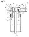
- Fig. 17 is a sectional view of an arrangement of the third modification example of the X-ray tube according to the second embodiment.
- the X-ray tube 2D (third modification example of the X-ray tube according to the second embodiment) has an inner tubular member 35 in place of the inner tubular member 31 of the X-ray tube 2A.
- the inner tubular member 35 has a cylindrical shape with a diameter slightly less than the inner diameter of the head 13 at the inner wall surface 19 and is positioned between the inner wall surface 19 of the head 13 and the anode tip 5a so as to surround the anode tip 5a.
- the inner tubular member 35 is positioned by a step 13b, formed below the inner wall surface 19 of the head 13.
- An inner wall surface 35j of the inner tubular member 35 is formed so as to be matched with the inner wall surface 13c of the head 13. A corner portion thus does not appear at a boundary between the inner wall surface 35j of the inner tubular member 35 and the inner wall surface 13c of the head 13, and discharge across the anode 5 and either of the inner wall surface 35j and the inner wall surface 13c is suppressed.
- the head 13 has an annular wall portion 13e that extends below the fused portion 9c of the bulb 9a and the connecting portion 9b inside the internal space R.
- the fused portion 9c is hidden from view from the anode 5.
- a lower end 13d of the annular head 13 is rounded into a round shape to suppress discharge to the anode 5.
- the present invention is not restricted to the above-described second embodiment and modification examples thereof and can be modified variously.
- the inner tubular member 31 is provided with the flat portions 31p, the flat portions 31p may be omitted.
- the bulb 9a and the head 13 are joined via the connecting portion 9b, the bulb 9a and the head 13 may be joined together directly.
- the target 5d is disposed as a separate member on the inclined surface 5c of the anode 5, the anode 5 and the target 5d can be made integral so that a part of the inclined surface 5c constitutes the target.
- the anode 5 has a shape having the inclined surface 5c disposed at the tip of a cylindrical column
- other shapes can be provided at the tip of the anode 5 by any of various types of carving. In this case, even when a corner-like portion is present at the tip of the anode, discharge across the anode tip and the exhaust port can be suppressed effectively by the inner tubular member 31.
- Fig. 18 is an exploded perspective view of an arrangement of an embodiment of the X-ray source according to the present invention.
- Fig. 19 is a sectional view of an internal structure of the X-ray source according to the embodiment.
- any of the X-ray tubes 1A to 1D according to the first embodiment and the X-ray tubes 2A to 2D according to the second embodiment can be applied to the X-ray source 100 according to the present invention, for the sake of simplicity, all X-ray tubes applicable to the X-ray source 100 shall be expressed simply as "X-ray tube 1" in the description that follows and in the relevant drawings.
- the X-ray source 100 includes a power supply unit 102, a first plate member 103, disposed at an upper surface side of an insulating block 102A and the power supply unit 102, a second plate member 104, disposed at a lower surface side of the insulating block 102A, four fastening spacer members 105, interposed between the first plate member 103 and the second plate member 104, and an X-ray tube 1, fixed above the first plate member 103 via a metal tubular member 106.
- the power supply unit 102 has a structure, with which a high voltage generating unit 102B, a high voltage line 102C, a socket 102D, etc., (see Fig. 19 ), are molded inside the insulating block 102A comprisedof an epoxy resin.
- the insulating block 102A of the power supply unit 102 has a short, rectangular column shape, with the mutually parallel upper surface and lower surface of substantially square shapes. At a central portion of the upper surface is disposed the cylindrical socket 102D, connected to the high voltage generating unit 102B via the high voltage line 102C. An annular wall portion 102E, positioned concentric to the socket 102D, is also disposed on the upper surface of the insulating block 102A. A conductive coating 108 is applied to peripheral surfaces of the insulating block 102A to make a potential thereof the GND potential (ground potential). A conductive tape may be adhered in place of coating the conductive coating.
- the first plate member 103 and the second plate member 104 are members that, for example, act together with the four fastening spacer members 105 and eight fastening screws 109 to clamp the insulating block 102A of the power supply unit 102 in the vertical direction in the figure.
- the first plate member 103 and the second plate member 104 are formed to substantially square shapes that are larger than the upper surface and the lower surface of the insulating block 102A.
- Screw insertion holes 103A and 104A, for insertion of the respective fastening screws 109, are formed respectively at four corners of the first plate member 103 and the second plate member 104.
- the four fastening spacer members 105 are formed to rectangular column shapes and are disposed at the four corners of the first plate member 103 and the second plate member 104.
- Each fastening spacer member 105 has a length slightly shorter than an interval between the upper surface and the lower surface of the insulating block 102A, that is, a length shorter than the interval by just a fastening allowance of the insulating block 102A.
- the metal tubular member 106 is formed to a cylindrical shape and has a mounting flange 106A formed at a base end thereof and fixed by screws across a sealing member to a periphery of the opening 103B of the first plate member 103.
- a peripheral surface at a tip of the metal tubular member 6 is formed to a tapered surface 106B.
- the metal tubular member 106 is formed to a tapered shape without any corner portions at the tip.
- An opening 106C, through which a bulb 7 of the X-ray tube 1 is inserted, is formed in a flat, tip surface that is continuous with the tapered surface 106B.
- the X-ray tube 1 includes the bulb 7, holding and housing the anode 5 in an insulated state, an upper portion 9c of the head 9, housing the reflecting type target 5d that is made electrically continuous with and formed at an inner end portion of the anode 5, and an electron gun housing unit 11, housing the electron gun 15 that emits an electron beam toward an electron incidence surface (reflection surface) of the target 5d.
- a target housing unit is formed by the bulb 7 and the head 9.
- the bulb 7 and the upper portion 9c of the head 9 are positioned so as to be matched in tube axis, and these tube axes are substantially orthogonal to a tube axis of the electron gun housing unit 11.
- a flange 9a for fixing to the tip surface of the metal tubular member 106, is formed between the bulb 7 and the upper portion 9c of the head 9.
- a base end 5a (portion at which a high voltage is applied from the power supply unit 102) of the anode 5 protrudes downward from a central portion of the bulb 7 (see Fig. 19 ).
- An exhaust tube is attached to the X-ray tube 1, and a sealed vacuum container is formed by interiors of the bulb 7, the upper portion 9c of the head 9, and the electron gun housing unit 11 being depressurized to a predetermined degree of vacuum via the exhaust tube.
- the base end 5a (high voltage application portion) is fitted into the socket 102D molded in the insulating block 102A of the power supply unit 102. High voltage is thereby supplied from the high voltage generating unit 102B and via the high voltage line 102C to the base end 5a.
- the electron gun 15, incorporated in the electron gun housing unit 11 emits electrons toward the electron incidence surface of the target 5d, X-rays, generated by the incidence of the electrons from the electron gun 15 onto the target 5d, are emitted from an X-ray emission window 10, fitted into an opening of the upper portion 9c of the head 9.
- the X-ray source 100 is assembled, for example, by the following procedure.
- the four fastening screws 109 inserted through the respective screw insertion holes 104A of the second plate member 104, are screwed into the respective screw holes 105A at the lower end surfaces of the four fastening spacer members 105.
- the four fastening screws 109 inserted through the respective screw insertion holes 103A of the first plate member 103, being screwed into the respective screw holes 105A at the upper end surfaces of the four fastening spacer members 105, the first plate member 103 and the second plate member 104 are mutually fastened while clamping the insulating block 102A in the vertical direction.
- a sealing member is interposed between the first plate member 103 and the upper surface of the insulating block 102A, and likewise, a sealing member is interposed between the second plate member 104 and the lower surface of the insulating block 102A.
- a high voltage insulating oil 110 which is a liquid insulating substance, is then injected into an interior of the metal tubular member 106 from the opening 106C of the metal tubular member 106 that is fixed above the first plate member 103.
- the bulb 7 of the X-ray tube 1 is then inserted from the opening 106C of the metal tubular member 106 into the interior of the metal tubular member 106 and immersed in the high voltage insulating oil 110.
- the base end 5a (high voltage application portion) that protrudes downward from the central portion of the bulb 7 is fitted into the socket 102D at the power supply unit 102 side.
- the flange 9a of the X-ray tube 1 is then fixed by screwing across the sealing member onto the tip surface of the metal tubular member 106.
- the annular wall portion 102E protruded from the upper surface of the insulating block 102A of the power supply unit 102, and the metal tubular member 106 are positioned concentric to the anode 5 of the X-ray tube 1 as shown in Fig. 19 . Also, the annular wall portion 102E protrudes to a height of surrounding and shielding the periphery of the base end 5a (high voltage application portion), which protrudes from the bulb 7 of the X-ray tube 1, from the metal tubular member 106.
- the X-ray source 100 when a high voltage is applied to the base end 5a of the X-ray tube 1 from the high voltage generating unit 102B of the power supply unit 102 and via the high voltage line 102C and the socket 102D, the high voltage is supplied to the target 5d via the anode 5.
- the electron gun 15, housed in the electron gun housing unit 11 emits electrons toward the electron incidence surface of the target 5d, housed in the upper portion 9c of the head 9, the electrons become incident on the target 5d.
- the X-rays that are thereby generated at the target 5d are emitted to the exterior via the X-ray emission window 10, fitted onto the opening of the upper portion 9c of the head 9.
- the metal tubular member 106 housing the bulb 7 of the X-ray tube 1 in a state of being immersed in the high voltage insulating oil 110, is protruded from and fixed above the exterior of the insulating block 102A of the power supply unit 2, that is, the first plate member 103.
- a good heat dissipating property is thus realized, and heat dissipation of the high voltage insulating oil 110 inside the metal tubular member 106 and the bulb 7 of the X-ray tube 1 can be promoted.
- the metal tubular member 106 has a cylindrical shape with the anode 5 disposed at the center. In this case, because the distance from the anode 5 to the metal tubular member 106 is made uniform, an electric field formed in a periphery of the anode 5 and the target 5d can be stabilized. The metal tubular member 106 can thus effectively discharge charges of the charged high voltage insulating oil 110.
- annular wall portion 102E protruded on the upper surface of the insulating block 102A of the power supply unit 102, surrounds the periphery of the base end 5a (high voltage application portion), protruding from the bulb 7 of the X-ray tube 1, and thereby shields the base end 5a from the metal tubular member 106. Abnormal discharge from the base end 5a to the metal tubular member 106 is thus prevented effectively.
- the X-ray source 100 has the structure with which the insulating block 102A of the power supply unit 102 is clamped between the first plate member 103 and the second plate member 104 that are fastened to each other via the four fastening spacer members 105.
- unwanted discharge phenomena and electric field disruptions in the power supply unit 102 are suppressed effectively.
- the X-ray source 100 is incorporated and used, for example, in an X-ray generating apparatus that irradiates X-rays onto a sample in a nondestructive inspection apparatus, with which an internal structure of the sample is observed in the form of a transmission image.
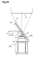
- Fig. 20 is a front view for describing actions of an X-ray source (including the X-ray tube according to the embodiment) that is incorporated, as a usage example of the X-ray source 100, in an X-ray generating apparatus of a nondestructive inspection apparatus.
- the X-ray source 100 irradiates X-rays to a sample plate SP, positioned between an X-ray camera XC and the X-ray source 100. That is, the X-ray source 100 irradiates X-rays onto the sample plate SP through the X-ray emission window 10 from an X-ray generation point XP of the target 5d, incorporated in the upper portion 9c of the head 9 that protrudes above the metal tubular member 106.
- the sample plate SP is normally positioned close to the X-ray generation point XP. Also, to observe the internal structure of the sample plate SP three-dimensionally, the sample plate SP is inclined around an axis orthogonal to a direction of irradiation of the X-rays.
- the observation point P of the sample plate SP can be made to approach the X-ray generation point XP only up to a distance, with which the sample plate SP contacts a tip corner portion of the metal tubular member 6, that is, only up to a distance at which a distance from the X-ray generating point XP to the observation point P becomes D1.
- the observation point P of the sample plate SP can be made to approach the X-ray generation point XP to a distance, with which the sample plate SP contacts the tapered surface 106B of the metal tubular member 106 as indicated by solid lines Fig. 20 , that is, to a distance at which the distance from the X-ray generating point XP to the observation point P becomes D2. Consequently, the transmission image of the observation point P of the sample plate SP can be magnified further and nondestructive inspection of the observation point P can be performed more precisely.
- the X-ray source 100 is not restricted to the above-described embodiment.
- a cross-sectional shape of an inner peripheral surface of the metal tubular member 106 is preferably circular
- a cross-sectional shape of an outer peripheral surface of the metal tubular member 106 is not restricted to being circular and may be a rectangular shape or other polygonal shape.
- the peripheral surface of the tip of the metal tubular member can be formed to be an inclined surface.
- the insulating block 102A of the power supply unit 102 may have a short, cylindrical shape, and the first plate member 103 and the second plate member 104 may correspondingly have disk shapes.
- the fastening spacer members 105 may have cylindrical shapes and the number thereof is not restricted to four.
- the structure of the X-ray tube 1 may be a structure with which the electron gun is disposed inside the bulb 7.
- the X-ray tube according to the present invention can be applied as an X-ray generating source in various X-ray imaging apparatuses that are frequently used for nondestructive, noncontact observations.
Landscapes
- X-Ray Techniques (AREA)
Abstract
Description
- The present invention relates to an X-ray tube taking out X-rays generated wherein toward an exterior, and an X-ray source in which the X-ray tube and a power supply unit are configured integrally.
- X-rays are electromagnetic waves that are highly transmitted through objects and are frequently used for nondestructive, noncontact observation of internal structures of objects. As a conventional X-ray irradiation apparatus applicable to such fields, an X-ray tube, described in
Patent Document 1 indicated below, is known. An X-ray generating unit of the X-ray tube described inPatent Document 1 has a tubular casing that houses a target, and an exhaust pipe, put in communication with an internal space, is mounted to the casing (seeFig. 4 , etc., of Patent Document 1). In manufacturing the X-ray tube, vacuum is drawn from the internal space of the casing via the exhaust pipe. After vacuum drawing, the exhaust pipe is closed and the internal space that houses the target is put in a vacuum state (state of being depressurized to a predetermined degree of vacuum).
Patent Document 1:U. S. Patent No. 6229876 - The present inventors have examined the conventional X-ray tubes, and as a result, have discovered the following problems. That is, in the conventional X-ray tube, the exhaust port for drawing vacuum is formed in an inner wall surface of the casing onto which the exhaust pipe is mounted, and at an edge of the exhaust port, a corner portion with a sharp tip is present at a boundary with the casing inner wall. When a high potential difference is generated across the casing and an anode during driving of the X-ray tube, an electric field across the casing and the anode may become disrupted due to an influence of the corner portion. A possibility of discharge occurring across the casing and a tip of the anode thus increases due to the presence of the corner portion that is inevitably formed due to forming of the exhaust port. However, in the conventional X-ray tube, no measures are taken to suppress such discharge and there was a possibility of destabilization of the X-ray output due to such discharge.
- The present invention has been developed to eliminate the problems described above. It is an object of the present invention to provide an X-ray tube having a structure for effectively suppressing discharge at a tip of an anode that is irradiated with electrons to generate X-rays, and to provide an X-ray source including the X-ray tube.
- An X-ray tube according to the present invention irradiates X-rays generated at an X-ray target to an exterior by making electrons emitted from an electron gun be incident on the X-ray target of an anode. The X-ray tube comprises a casing, an irradiation window (X-ray emission window) disposed on the casing; an exhaust port, and a shielding structure. The casing defines an internal space housing a tip of the anode that is irradiated with electrons. The irradiation window is disposed on the casing defining the internal space, in order to take out the X-rays generated at the X-ray target to the exterior of the casing. The exhaust port is prepared for vacuum drawing of the internal space and is disposed at an inner wall surface of the casing. In particular, the shielding structure is disposed in the internal space of the casing so as to hide the exhaust port from the tip of the anode.
- Here, as a first aspect, the shielding structure preferably includes a shielding member comprised of a conductive material and having an inner side surface that faces the tip of the anode, and an outer side surface opposing the inner side surface.
- In the X-ray tube having the above-described structure, the exhaust port is disposed at the inner wall surface of the casing. A corner portion with a sharp tip is thus formed as a boundary between an edge of the exhaust port and the inner wall surface of the casing. The present X-ray tube is thus provided with a structure, with which the exhaust port is hidden from the tip of the anode by the shielding member. Thus, in this X-ray tube, disruption of an electric field across the anode and the edge of the exhaust port during driving is alleviated and discharge at the tip of the anode is suppressed effectively.
- In order to exhibit the above action effectively, the shielding member is preferably disposed between the tip of the anode and the exhaust port in a state of being separated by a predetermined distance from the inner wall surface at the exhaust port side of the casing. In addition, at least the inner side surface of the shielding member that faces the tip of the anode preferably has an area larger than an opening area of the exhaust port. In this configuration, the edge of the exhaust port (the corner portion with the sharp tip) can be covered reliably. Also, during manufacture of the X-ray tube, vacuuming of the internal space can be performed using a gap between the shielding member and the inner wall surface at the exhaust port side as a passage for air.
- The shielding member may also be disposed in the internal space in a state of being separated by a predetermined distance from an inner wall surface at the irradiation window side of the casing. In this configuration, during manufacture of the X-ray tube, vacuuming of the internal space can be performed using a gap between the shielding member and the inner wall surface at the irradiation window side as a passage for air.
- The shielding member may be provided with a plurality of through holes each communicating between the inner side surface facing the tip of the anode and the outer side surface opposing the inner side surface. In this case, at the tiem of vacuuming the internal space during manufacture of the X-ray tube, the through holes serve as passages for air from the internal space and vacuum drawing can thus be performed efficiently.
- The shielding member may be a part of the casing that extends from an inner wall surface of the casing to the internal space. In this case, the inner side surface of the shielding member that opposes the tip of the anode is matched with the inner wall surface of the portion of the casing. In this configuration, the surface of the shielding member and the inner wall surface of the casing can be made smoothly continuous with respect to each other. Disruption of the electric field is thus alleviated and the discharge at the tip of the anode can be suppressed further.
- The shielding member may have a plurality of through holes each putting the inner side surface and the outer side surface in communication, and be disposed so that the inner side surface facing the tip of the anode is matched with the inner wall surface of the casing. In this case, because the exhaust port is closed by the shielding member, the shielding member is required to have the plurality of through holes that serve as passages for air during vacuum drawing. In the X-ray tube, because the shielding member that closes the exhaust port is formed flush to the inner wall surface of the casing at which the exhaust port is formed, a corner portion with a sharp tip does not appear at the edge of the exhaust port and disruption of the electric field across the tip of the anode and the exhaust port is alleviated. As a result, the discharge at the tip of the anode is suppressed effectively. Because the plurality of communicating holes formed in the shielding member serve as passages for air, vacuum drawing of the internal space during manufacture can also be carried out without any problem.
- Also, in the X-ray tube according to the present invention, the shielding structure may be realized according to a second aspect that differs from the first aspect described above. Specifically, the casing may be constituted of a first anode housing portion and a second anode housing portion, and an inner tubular member may be disposed as the shielding structure in the internal space of the casing. The first anode housing portion is a hollow member comprised of a conductive material, the first anode housing portion surrounding the tip of the anode that has the exhaust port disposed at an inner wall surface thereof and having the irradiation window. The second anode housing portion defines an internal space for housing the anode together with the first anode housing portion, by being joined to the first anode housing portion. The inner tubular member that is the shielding structure of the second mode is a hollow member disposed in the internal space of the casing so as to surround at least the tip of the anode and, by a part thereof being positioned between the inner wall surface of the first anode housing portion and the tip of the anode in a state of being separated by a predetermined distance from the inner wall surface of the first anode housing portion, functions to hide the exhaust port from the tip of the anode.
- In the X-ray tube having the above-described shielding structure of the second aspect, the exhaust port, disposed at the inner wall surface of the first anode housing portion, is hidden from the tip of the anode by the inner tubular member, at least a part of which is positioned between the tip of the anode and the inner wall surface of the first anode housing portion. Thus, in this X-ray tube, even when a corner portion appears as a boundary between the edge of the exhaust port and the inner wall surface of the first anode housing portion, disruption of the electric field across the anode and the edge of the exhaust port during driving is alleviated by the inner tubular member. Also, because discharge at the tip of the anode is suppressed effectively, destabilization of X-ray output of the X-ray tube is suppressed. During manufacture of the X-ray tube, vacuuming of the internal space can be performed using a gap between the inner tubular member and the inner wall surface of the first anode housing portion as a passage for air.
- Even when the above-described inner tubular member is employed as the shielding structure according to the second mode, a gap is preferably formed between an end of the inner tubular member and an inner wall surface at the irradiation window side of the first anode housing portion. In this configuration, during manufacture of the X-ray tube, vacuum drawing of the internal space can be performed using the gap between the inner tubular member and the inner wall surface at the irradiation window side of the first anode housing portion as a passage for air.
- The inner tubular member preferably has a plurality of through holes disposed at least at a part positioned between the inner wall surface of the first anode housing portion and the tip of the anode. In this case, because the through holes themselves serve as passages for air from the internal space during vacuum drawing of the internal space during manufacture, the vacuum drawing can be performed efficiently.
- In the X-ray tube according to the present invention, the first anode housing portion preferably has a head comprised of a conductive material, and the second anode housing portion having a bulb comprised of an electrically insulating material and a connecting portion comprised of a conductive material, the connecting portion being joined to an end of the bulb and to the head of the first anode housing portion. In this configuration, the inner tubular member has a shape that extends toward the second anode housing portion side in the internal space so as to hide a joined portion of the bulb and the connecting portion from the anode. That is, in this X-ray tube, discharge occurs comparatively readily across the anode and the joined portion of the bulb comprised of the electrically insulating material, and the connecting portion comprised of the conductive material. Thus, in this X-ray tube, the joined portion is hidden from the anode by employment of the inner tubular member with the above-described structure. Disruption of the electric field across the joined portion and the anode is thus alleviated and the discharge across the joined portion and the anode is suppressed effectively. As a result, destabilization of the X-ray output of the X-ray tube is suppressed.
- In the X-ray tube according to the present invention, the second anode housing portion preferably has a bulb comprised of an electrically insulating material, and the first anode housing portion has a head comprised of a conductive material, and a connecting portion comprised of a conductive material, the connecting portion being disposed at an end of the head and joined to the bulb of the second anode housing portion. The inner tubular member preferably has a shape that extends toward the second anode housing portion side in the internal space so as to hide a joined portion of the bulb and the connecting portion from the anode. In the X-ray tube with this structure, discharge occurs comparatively readily across the anode and the joined portion of the bulb comprised of the electrically insulating material, and the connecting portion comprised of the conductive material. Thus, in this X-ray tube, the joined portion is hidden from the anode by employment of the inner tubular member with the above-described structure. Disruption of the electric field across the joined portion and the anode is thus alleviated and the discharge across the joined portion and the anode is suppressed effectively. As a result, destabilization of the X-ray output of the X-ray tube is suppressed.
- The inner tubular member may have a loopback portion, at which an end at the second anode housing portion side is looped back into a round shape. In this case, it is preferable that a tip of the loopback portion is joined to the first anode housing portion and a through hole is formed in the loopback portion. In this configuration, because the second anode housing portion side end of the inner tubular member has the round shape, a corner portion with a sharp tip is not formed. Disruption of the electric field across the end and the anode is thus suppressed effectively. As a result, discharge across the end and the anode is suppressed and destabilization of the X-ray output of the X-ray tube can be suppressed. Also, in this case, a space is formed in a region surrounded by the looped back inner tubular member and the first anode housing portion. However, because the through hole formed in the loopback portion serves as a passage for air during vacuum drawing of the internal space in the manufacture of the X-ray tube, retention of air in this space is prevented.
- Furthermore, an X-ray source according to the present invention comprises the X-ray tube with the above-described structure (X-ray tube according to the present invention), and a power supply unit supplying a voltage for generating X-rays at the X-ray target toward the anode at which the X-ray target is disposed.
- The present invention will be more fully understood from the detailed description given hereinbelow and the accompanying drawings, which are given by way of illustration only and are not to be considered as limiting the present invention.
- Further scope of applicability of the present invention will become apparent from the detailed description given hereinafter. However, it should be understood that the detailed description and specific examples, while indicating preferred embodiments of the invention, are given by way of illustration only, since various changes and modifications within the scope of the invention will be apparent to those skilled in the art from this detailed description.
- In accordance with the X-ray tube according to the present invention, by employment of a special shielding structure inside the casing, discharge at the tip of the anode is suppressed effectively.
-
-
Fig. 1 is a perspective view of an arrangement of a first embodiment of an X-ray tube according to the present invention; -
Fig. 2 is a vertical sectional view of the X-ray tube according to the first embodiment shown inFig. 1 ; -
Fig. 3 is a horizontal sectional view of the X-ray tube according to the first embodiment shown inFig. 1 ; -
Fig. 4 is a perspective view of an arrangement of a first modification example of the X-ray tube according to the first embodiment; -
Fig. 5 is a sectional view of the X-ray tube shown inFig. 4 (first modification example of the X-ray tube according to the first embodiment); -
Fig. 6 is a perspective view of an arrangement of a second modification example of the X-ray tube according to the first embodiment; -
Fig. 7 is a sectional view of the X-ray tube shown inFig. 6 (second modification example of the X-ray tube according to the first embodiment); -
Fig. 8 is a perspective view of an arrangement of a third modification example of the X-ray tube according to the first embodiment; -
Fig. 9 is a sectional view of the X-ray tube shown inFig. 8 (third modification example of the X-ray tube according to the first embodiment); -
Fig. 10 is a perspective view of an arrangement of a second embodiment of an X-ray tube according to the present invention; -
Fig. 11 is an exploded perspective view of the X-ray tube according to the second embodiment shown inFig. 10 ; -
Fig. 12 is a sectional view of the X-ray tube according to the second embodiment shown inFig. 10 ; -
Fig. 13 is a sectional view taken across a central axis of an exhaust tube of the X-ray tube according to the second embodiment shown inFig. 10 ; -
Fig. 14 is a sectional view of a vicinity of a mounting portion of the exhaust tube of the X-ray tube according to the second embodiment shown inFig. 10 ; -
Fig. 15 is a sectional view of an arrangement of a first modification example of the X-ray tube according to the second embodiment; -
Fig. 16 is a sectional view of principal portions of a third modification example of the X-ray tube according to the second embodiment, that is, a modification example of the X-ray tube shown inFig. 15 (second modification example of the X-ray tube according to the second embodiment); -
Fig. 17 is a sectional view of an arrangement of a third modification example of the X-ray tube according to the second embodiment; -
Fig. 18 is an exploded perspective view of an arrangement of an embodiment of an X-ray source according to the present invention; -
Fig. 19 is a sectional view of an internal structure of the X-ray source according to the embodiment; and -
Fig. 20 is a front view for describing actions of the X-ray source (including the X-ray tube according to the embodiment) incorporated in an X-ray generating apparatus of a nondestructive inspection apparatus. - 1A, 1B, 1C, 1D, 2A, 2B, 2C, 2D ... X-ray tube; 3 ... electron gun; 5 ... anode; 5a ... anode tip; 9 ... body portion (second anode housing portion); 9a ... bulb; 9b ... connecting portion; 9c ... fused portion (joined portion); 13 ... head (first anode housing portion); 14 ... electron gun housing unit; 15 ... irradiation window; 17, 57 ... exhaust port; 19, 59 ... exhaust port side inner wall surface; 25, 61, 63, 65 ... shielding member; 29 ... irradiation window side inner wall surface; 31, 33, 35 ... inner tubular member; 31d ... loopback portion; 31e ... free end of loopback portion; 31f ... through hole; 31k ... communicating hole; 58 ... inner wall surface; 61a, 63a ... shielding member surface; 63f, 65f ... communicating hole; R ... internal space; d1, d2, d3, d4, S1, S2 ... gap; 100 ... X-ray source; 102 ... power supply unit; 102A ... insulating block; 102B ... high voltage generating unit; 102C ... high voltage line; 102D ... socket; 103 ... first plate member; 103A ... screw insertion hole; 104 ... second plate member; 104A ... screw insertion hole; 105 ... fastening spacer member; 150A ... screw hole; 106 ... metal tubular member; 106A ... mounting flange; 106B ... relief surface; 106C ... insertion hole; 108 ... conductive coating; 109 ... fastening screw; 110 ... high voltage insulation oil; XC ... X-ray camera; SP ... sample plate; P ... observation point; and XP ... X-ray generation point.
- In the following, embodiments of an X-ray tube and an X-ray source, including the X-ray tube according to the present invention will be explained in detail with reference to
Figs. 1 to 20 . In the description of the drawings, identical or corresponding components are designated by the same reference numerals, and overlapping description is omitted. - (First Embodiment)
First, a first embodiment of an X-ray tube according to the present invention will be explained with reference toFigs. 1 to 3 .Fig. 1 is a perspective view of an arrangement of the first embodiment of the X-ray tube according to the present invention.Fig. 2 is a vertical sectional view of the X-ray tube according to the first embodiment shown inFig. 1 .Fig. 3 is a horizontal sectional view of the X-ray tube according to the first embodiment shown inFig. 1 . - As shown in
Figs. 1 to 3 , theX-ray tube 1A makes electrons, emitted from anelectron gun 3, be incident on atarget 5d, which is an electron incidence portion (X-ray generating portion) disposed at atip 5a of ananode 5 in vacuum, and irradiates X-rays, generated as a result of the incidence of electrons, to an exterior. TheX-ray tube 1A includes aglass bulb 9, holding the rod-like anode 5 in an insulated state, and anX-ray generating unit 11, housing theanode tip 5a and generating X-rays. - The
X-ray generating unit 11 has ahead 13, which is a metal casing that houses theanode tip 5a, and substantially the entirety of theanode 5 is housed in a sealed internal space R, defined by thehead 13 and thebulb 9, in a state of being insulated from thehead 13. Aninclined surface 5c is disposed at an end surface of theanode tip 5a, and on theinclined surface 5c is disposed thetarget 5d that generates X-rays with a desired energy upon the incidence of electrons. Theanode tip 5a is surrounded by aninner wall surface 19 of thehead 13 forming a cylindrical surface coaxial to theanode 5. Theelectron gun 3 is housed in an electrongun housing unit 14, mounted onto thehead 13, and a tip of theelectron gun 3 is directed toward theanode tip 5a. That is, an axial line of theelectron gun 3 and an axial line of theanode 5 are made substantially orthogonal to each other so that the electrons emitted from theelectron gun 3 are made incident on thetarget 5d on theinclined surface 5c, formed so as to face theelectron gun 3. Furthermore, at an end at theanode tip 5a side of thehead 13 is disposed a circular irradiation window 15 (X-ray emitting window) comprised of a material of high X-ray transmittance for transmitting the X-rays generated at thetarget 5d and thereby irradiating the X-rays to the exterior. - In order to put the internal space R in a vacuum state (a state of being decompressed to a predetermined degree of vacuum), an
exhaust port 17, for evacuating air inside the internal space R, is disposed at theinner wall surface 19 of thehead 13. On the other hand, anexhaust tube 21, put in communication with the internal space R via theexhaust port 17, is mounted on an outer wall surface of thehead 13. In manufacturing the X-ray tube, by performing vacuum drawing of the internal space R via theexhaust port 17 and theexhaust tube 21 and thereafter closing the tube opening by squashing theexhaust tube 21, etc., the internal space R is sealed in a vacuum state. In this process, theexhaust port 17 is left open to the internal space R even after completion of assembly of the X-ray tube. - In the
X-ray tube 1A, abase end 5b (high voltage application portion) of theanode 5, exposed from thebulb 9, is connected to a high voltage supply circuit. During driving, a high voltage of approximately 100kV is applied from the high voltage supply circuit to theanode 5 via thebase end 5b. When the electrons emitted from theelectron gun 3 in this state become incident on thetarget 5d, X-rays are generated from thetarget 5d by the incidence of electrons. The generated X-rays are transmitted through theirradiation window 15 and irradiated to the exterior. - Because the high voltage is thus applied to the
anode 5 during driving, a high potential difference arises across theanode 5 and thehead 13, which is the metal casing. In particular, because theanode tip 5a is housed so as to be surrounded by thehead 13, there is a problem of discharge occurring across theanode tip 5a and theinner wall surface 19 of thehead 13. Here, at an edge of theexhaust port 17, formed in theinner wall surface 19, a corner portion with a sharp tip is present as a boundary with theinner wall surface 19. An electric field across theanode 5 and thehead 13 is disrupted due to an influence of the corner portion, and consequently, there is an especially high possibility of discharge occurring across the edge of theexhaust port 17 and theanode tip 5a. Because when the discharge occurs, problems, such as destabilization of an X-ray output of theX-ray tube 1A, occur, the discharge must be suppressed. - Thus, in the
X-ray tube 1A, in order to suppress the discharge across the edge of theexhaust port 17 and theanode tip 5a, a special shielding structure (first mode) is employed. That is, a partitioning-screen-like shielding member 25, hiding theexhaust port 17 from theanode tip 5a, is disposed between theanode tip 5a and theexhaust port 17. The shieldingmember 25 is a flat plate member comprised of a conductive material, the shieldingmember 25 being processed to a rectangular shape and having an area larger than an open aperture of theexhaust port 17. The shieldingmember 25 has two opposing sides fixed to theinner wall surface 19 and is disposed so as to cover theexhaust port 17 across a gap d1 from theinner wall surface 19 at a central portion. The shieldingmember 25 extends very close to aninner wall surface 29, on which theirradiation window 15 is disposed, so that a small gap d2 is formed between the shieldingmember 25 and theinner wall surface 29. By the shieldingmember 25, the edge of theexhaust port 17 is prevented from being viewed from theanode tip 5a. - In the
X-ray tube 1A, by such a shieldingmember 25 being disposed, disruption of the electric field across theanode tip 5a and the edge of theexhaust port 17 is alleviated. Discharge across theanode tip 5a and the edge of theexhaust port 17 is thus suppressed. Also, by the gaps d1 and d2, an interior of theexhaust tube 21 and the internal space R are put in communication, and because the gaps d1 and d2 function as passages for air, vacuum drawing of the internal space R via theexhaust port 17 can be performed without any problem during manufacture. Although vacuum drawing will take some time, the shieldingmember 25 may be disposed so that the gap d2 is not formed. In this case, vacuum drawing can be performed using just the gap d1 as a passage for air. The shieldingmember 25 is not limited to being a flat plate member and may be a curved plate member with a curvature larger than that of the inner wall surface of thehead 13. - (First Modification Example of the X-ray Tube According to the First Embodiment)
Subsequently, a first modification example of the X-ray tube according to the first embodiment will be explained with reference toFigs. 4 and5 .Fig. 4 is a perspective view of an arrangement of the first modification example of the X-ray tube according to the first embodiment.Fig. 5 is a sectional view of theX-ray tube 1B shown inFig. 4 . - The
X-ray tube 1B, shown inFigs. 4 and5 , differs from theX-ray tube 1 A of the first embodiment in a shielding member structure that hides anexhaust port 57 from theanode tip 5a. In theX-ray tube 1B, theexhaust port 57 is positioned at aninner wall surface 59 formed by digging into a part of aninner wall surface 58 in a direction of an outer wall surface of thehead 13. A shieldingmember 61 for hiding theexhaust port 57 from theanode tip 5a is disposed between theexhaust port 57 and theanode tip 5a. The shieldingmember 61 has aninner side surface 61a, facing theanode tip 5a and being matched with the inner wall surface 58 (and being practically a part of thehead 13 in the present modification example), and has a rectangular shape with an area larger than the open aperture of theexhaust port 57. The shieldingmember 61 is disposed so that a gap d3 is formed across from theexhaust port 57. The shieldingmember 61 extends very close to aninner wall surface 29, on which theirradiation window 15 is disposed, so that a small gap d4 is formed between the shieldingmember 61 and theinner wall surface 29. By the shieldingmember 61, the edge of theexhaust port 57 is prevented from being viewed from theanode tip 5a. - The shielding
member 61 and theexhaust port 57 with the above-described structure is prepared by carving out a region of rectangular parallelepiped shape sandwiched between the shieldingmember 61 and theinner wall surface 59 in thehead 13 while leaving the shieldingmember 61 and thereafter forming theexhaust port 57 and the gap d4. Or, theinner wall surface 59 may be formed by digging into theinner wall surface 58 and, after forming theexhaust port 57 in theinner wall surface 59, installing the shieldingmember 61 as a separate member so that its inner side surface is matched with theinner wall surface 58. - In the
X-ray tube 1B, by the provision of the shieldingmember 61, disruption of an electric field across theanode tip 5a and theexhaust port 57 is alleviated. Discharge across theanode tip 5a and the edge of theexhaust port 57 can thus be suppressed. Also, by the gaps d3 and d4, the interior of theexhaust tube 21 and the internal space R are put in communication, and because the gaps d3 and d4 function as passages for air, vacuum drawing of the internal space R via theexhaust port 57 can be performed without any problem during manufacture. Also, by theinner side surface 61a of shieldingmember 61 being matched with theinner wall surface 58 that surrounds theanode tip 5a, the inner side surface 61 a of the shieldingmember 61 is made smoothly continuous with theinner wall surface 58. In this configuration, disruption of the electric field around thetarget tip 5a due to the shieldingmember 61 can thus be minimized. - (Second Modification Example of the X-ray Tube According to the First Embodiment)
Subsequently, a second modification example of the X-ray tube according to the first embodiment will be explained with reference toFigs. 6 and7 .Fig. 6 is a perspective view of an arrangement of the second modification example of the X-ray tube according to the first embodiment.Fig. 7 is a sectional view of theX-ray tube 1C shown inFig. 6 . - The
X-ray tube 1C, shown inFigs. 6 and7 differs from theX-ray tube 1B of the second embodiment in a structure of a shieldingmember 63. The shieldingmember 63 is a mesh-like conductive member provided with a plurality of throughholes 63 f and has the same shape as the above-describedshielding member 61. The shieldingmember 63 is formed so that aninner side surface 63a, facing theanode tip 5a, is matched with theinner wall surface 58 that surrounds theanode tip 5a. - Even in accordance with the shielding
member 63, by making the throughholes 63f fine, disruption of the electric field across theanode tip 5a and the edge of theexhaust port 57 is alleviated in similar to the shieldingmember 61 in theX-ray tube 1B. Discharge across theanode tip 5a and the edge of theexhaust port 57 can thus be suppressed effectively with theX-ray tube 1C as well. Because in the process of vacuum drawing of the internal space R during manufacture not only the gaps d3 and d4 but the throughholes 63f also function as passages for air, smooth vacuum drawing is enabled. As a hole diameter of the throughholes 63f, 0.1 to 1mm is preferable for alleviating the disruption of the electrical field and performing smooth vacuum drawing. - (Third Modification Example of the X-ray Tube According to the First Embodiment)
A third modification example of the X-ray tube according to the first embodiment shall now be described with reference toFigs. 8 and9 .Fig. 8 is a perspective view of an arrangement of the third modification example of the X-ray tube according to the first embodiment.Fig. 9 is a sectional view of theX-ray tube 1D shown inFig. 8 . - The
X-ray tube 1D, shown inFigs. 8 and9 , differs from theX-ray tube 1 A of the first embodiment in a structure of a shielding member that hides theexhaust port 17 from theanode tip 5a. The shieldingmember 65 is a mesh-like conductive member, provided with a plurality of throughholes 65f and disposed so as to close theexhaust port 17 while an inner side surface, facing theanode 5, is matched with theinner wall surface 19. - In the shielding
member 65, because an end portion does not appear at theinner wall surface 19 at the edge of theexhaust port 17, disruption of the electric field across theanode tip 5a and the edge of theexhaust port 57 is alleviated. Discharge across theanode tip 5a and the edge of theexhaust port 17 can thus be suppressed. Also, the interior of theexhaust tube 21 and the internal space R are put in communication by the plurality of throughholes 65f, provided in the shieldingmember 65, and the throughholes 65f function as passages for air. Vacuum drawing of the internal space R via theexhaust port 17 can thus be performed without any problem during manufacture. As a hole diameter of the throughholes 65f, 0.1 to 1mm is preferable for alleviating the disruption of the electrical field and performing smooth vacuum drawing. - The present invention is not restricted to the above-described first embodiment and modification examples thereof and can be modified variously. For example, although the
target 5d is disposed as a separate member on theinclined surface 5c of theanode 5, theanode 5 and thetarget 5d can be configured integrally so that a part of theinclined surface 5c constitutes the target. Also, although theanode 5 has a shape having theinclined surface 5c disposed at the tip of a cylindrical column, other shapes can be provided at the tip of theanode 5 by any of various types of carving. In this case, even if a corner-like portion is present at the tip of the anode, discharge across the anode tip and the exhaust port can be suppressed effectively by the shielding member. - (Second Embodiment)
Next, an arrangement of a second embodiment of an X-ray tube according to the present invention will be explained with reference to Vs. 10 to 14.Fig. 10 is a perspective view of the arrangement of the second embodiment of the X-ray tube according to the present invention.Fig. 11 is an exploded perspective view of theX-ray tube 2A according to the second embodiment shown inFig. 10 .Fig. 12 is a sectional view of theX-ray tube 2A according to the second embodiment shown inFig. 10 .Fig. 13 is a sectional view taken across a central axis of an exhaust tube of theX-ray tube 2A according to the second embodiment shown inFig. 10 .Fig. 14 is a sectional view of a vicinity of a mounting portion of the exhaust tube of theX-ray tube 2A according to the second embodiment shown inFig. 10 . - As shown in
Figs. 10 to 13 , in similar to theX-ray tube 1A according to the first embodiment, theX-ray tube 2A makes electrons, emitted from theelectron gun 3, be incident on thetarget 5d, which is the electron incidence portion (X-ray generating portion) disposed at thetip 5a of theanode 5 in vacuum, and irradiates X-rays, generated as the result of the incidence of electrons, to the exterior. TheX-ray tube 2A includes a body portion (second anode housing portion) 9, holding the rod-like anode 5 in an insulated state, and the head (first anode housing portion) 13, which is the metal casing that surrounds theanode tip 5a. Thebody portion 9 is constituted of abulb 9a comprised of glass, which is an electrically insulating material, and a connectingportion 9b connecting thebulb 9a and thehead 13. One end side of thebulb 9a is open and the other end side holds theanode 5. At the open side of thebulb 9a, one end of the cylindrical connectingportion 9b, which is comprised of metal, is joined by fusing. An outwardly extending flange is disposed at the other end of the connectingportion 9b, and the connectingportion 9b is welded to thehead 13 at this flange. That is, thebulb 9a and thehead 13 are connected via the connectingportion 9b. By thebulb 9a, thehead 13, and the connectingportion 9b that are thus connected, the sealed internal space R is defined. Substantially the entirety of theanode 5 is housed inside the internal space R in a state of being insulated from thehead 13 and the connectingportion 9b. Theinclined surface 5c is disposed at theanode tip 5a, and on theinclined surface 5c is disposed thetarget 5d that generates the X-rays with the desired energy upon the incidence of electrons. - As another example, the first anode housing portion may be configured by integrally disposing the
tubular connecting portion 9b, for fusing with thebulb 9a, at an end of thehead 13. In this case, thebulb 9a constitutes the second anode housing portion. - The
head 13 has inner wall surfaces 19 and 20, constituting cylindrical surfaces coaxial to theanode 5, and theanode tip 5a is surrounded by the inner wall surfaces 19 and 20. The electrongun housing unit 14, housing theelectron gun 3, is mounted to a mountinghole 13a, formed so as to penetrate through a side wall of thehead 13. Theelectron gun 3 is positioned while the axial line of theelectron gun 3 and the axial line of theanode 5 are made substantially orthogonal to each other. That is, the tip of theelectron gun 3 is directed toward theanode tip 5a so that the electrons emitted from theelectron gun 3 are made incident on thetarget 5d on theinclined surface 5c, formed so as to face theelectron gun 3. Furthermore, at the end at theanode tip 5a side of thehead 13, which is the metal casing, is disposed the circular irradiation window 15 (X-ray emitting window) comprised of a material of high X-ray transmittance for transmitting the X-rays generated at thetarget 5d and thereby irradiating the X-rays to the exterior. - In order to put the internal space R in a vacuum state (a state of being decompressed to a predetermined degree of vacuum), the
exhaust port 17, for evacuating air inside the internal space R, is disposed at theinner wall surface 19 of thehead 13. Furthermore, theexhaust tube 21, put in communication with the internal space R via theexhaust port 17, is mounted on the outer wall surface of thehead 13. In manufacturing the X-ray tube, by performing vacuum drawing of the internal space R via theexhaust port 17 and theexhaust tube 21 and thereafter closing the tube opening by squashing theexhaust tube 21, etc., the internal space R is sealed in a vacuum state. In this process, theexhaust port 17 is left open to the internal space R even after completion of assembly of the X-ray tube. Although, in the present embodiment, theexhaust port 17 is formed at aninner wall surface 19 position diagonally in front of the mountinghole 13a, theexhaust port 17 may be formed at any position of theinner wall surface - In the
X-ray tube 2A, thebase end 5b (high voltage application portion) of theanode 5, exposed from thebulb 9, is connected to the high voltage supply circuit. During driving, the high voltage of approximately 100kV is applied from the high voltage supply circuit to theanode 5, including thetarget 5d, via thebase end 5b. When the electrons emitted from theelectron gun 3 in this state become incident on thetarget 5d, X-rays are generated from thetarget 5d by the incidence of electrons. The generated X-rays are transmitted through theirradiation window 15 and irradiated to the exterior. In similar to the first embodiment, the terms, "upper," "lower," etc., are used with theirradiation window 15 side being the upper side and thebase end 5b side of theanode 5 being the lower side in the description of the second embodiment as well. - Because the high voltage is thus applied to the
anode 5 during driving, a high potential difference arises across theanode 5 and thehead 13. In particular, theanode tip 5a is housed so as to be surrounded by thehead 13. There is thus a problem of discharge occurring across theanode tip 5a and theinner wall surface 19 of thehead 13. Here, as shown inFig. 14 , at the edge of theexhaust port 17, formed in theinner wall surface 19, anabrupt corner portion 17e appears at a boundary between aninner wall surface 21a of theexhaust tube 21 and anend surface 21b of theexhaust tube 21 and anabrupt corner portion 17f appears at a boundary between theexhaust port 17 and theinner wall surface 19. The electric field across theanode 5 and thehead 13 is disrupted due to influence of thecorner portions exhaust port 17 and theanode tip 5a. Because when the discharge occurs, problems, such as destabilization of the X-ray output of theX-ray tube 2A, occur, the discharge must be suppressed. - Thus, in the
X-ray tube 2A, in order to suppress the discharge across the edge of theexhaust port 17 and theanode tip 5a, a special shielding structure (second mode) is employed. That is, aninner tubular member 31 is disposed between theinner wall surface 19 of thehead 13 and theanode tip 5a. Theinner tubular member 31 is a conductive member comprised of metal and has a thickness thinner than thehead 31, theinner tubular member 31 having a cylindrical shape that surrounds theanode tip 5a. By the provision of such aninner tubular member 31, in theX-ray tube 2A, theexhaust port 17 is hidden from theanode tip 5a. That is, the edge of theexhaust port 17 is prevented from being viewed from theanode tip 5a. - The
inner wall surface 20, coaxial to theinner wall surface 19 of thehead 13 and constituting a cylindrical surface slightly smaller in diameter than theinner wall surface 19, is formed below theinner wall surface 19. On the other hand, an outer diameter of theinner tubular member 31 is set substantially equal to an inner diameter of thehead 13 at theinner wall surface 20. By anouter wall surface 31 a of thecylindrical portion 31 contacting theinner wall surface 20 across its entire periphery, thecylindrical portion 31 is disposed so as to be coaxial to theanode 5 and theinner wall surface 19 of thehead 13. By this positional relationship, asmall gap S 1 is formed between theouter wall surface 31 a of theinner tubular member 31 and theinner wall surface 19 of thehead 13. Furthermore, theinner tubular member 31 extends very close to theinner wall surface 29, on which theirradiation window 15 is disposed, so that a small gap S2 is formed between anupper end 31b of theinner tubular member 31 and theinner wall surface 29. By the above structure, the internal space R is put in communication with the interior of theexhaust tube 21 via the gaps S 1 and S2, and in the process of vacuum drawing of the internal space R, the gaps S 1 and S2 function as passages for air. - A
lower end 31c side of theinner tubular member 31 protrudes from a lower end of thehead 13 and extends below a fused portion (joined portion) 9c of thebulb 9a and the connectingportion 9b. By this structure, theinner tubular member 31 is made present between the fusedportion 9c and thetarget 5. The fusedportion 9c is thus hidden from view from theanode 5 by theinner tubular member 31. Thelower end 31 c of theinner tubular member 31 is looped back into a round shape with a curved surface and afree end 31e of aloopback portion 31d facing thebulb 9a side is joined by brazing to alower end surface 13 c of thehead 13. - Because the
lower end 31c of theinner tubular member 31 is thus looped back into the round shape, a corner portion does not appear at the lower end of theinner tubular member 31. Disruption of an electric field across the inner tubular memberlower end 31 c and theanode 5 is thus suppressed, and discharge across thelower end 31 c of the inner tubular member and theanode 5 can be suppressed effectively. Also, by thelower end 31 c of the inner tubular member being looped back, a small space Q, surrounded by the looped backinner tubular member 31 and thelower end surface 13c of thehead 13, is formed. Throughholes 31f, for putting the small space Q in communication with the internal space R are thus formed in theloopback portion 31d. The throughholes 31f thus serve as passages for air during vacuum drawing of the internal space R and retention of air in the small space Q is prevented. - In the
inner tubular member 31, aninsertion hole 31h is formed at a position corresponding to theelectron gun 3, and atip 3a of a housing container that houses theelectron gun 3 is inserted into theinsertion hole 31h and becomes exposed at theanode tip 5a side. A pair offlat portions 31p, parallel to the axial line of theelectron gun 3, are formed on theinner tubular member 31. Theflat portions 31p are positioned symmetrically so as to sandwich theinsertion hole 31h in between and have shapes that bulge toward theanode tip 5a side from aninner wall surface 31j. Theflat portions 31p function as electrodes for putting the electric field, via which the electrons emitted from theelectron gun 3 reach thetarget 5d, into a desired state. - In the
X-ray tube 2A, by the provision of the above-described innertubular member 31, disruption of the electric field across theanode tip 5a and the edge of theexhaust port 17 is alleviated. Thus, discharge across theanode tip 5a and the edge of theexhaust port 17 is suppressed. As a result, in theX-ray tube 2A, destabilization of the X-ray output due to discharge is suppressed and stable X-ray irradiation is enabled. Also, by the gaps S 1 and S2, the interior of theexhaust tube 21 and the internal space R are put in communication, and because the gaps S1 and S2 function as passages for air, vacuum drawing of the internal space R via theexhaust port 17 can be performed without any problem during manufacture of theX-ray tube 2A. - Also, rear sides of the
flat portions 31p are processed to shapes that are recessed from theouter wall surface 31a. Thus a comparatively wide space, corresponding to the amount of recess from theouter wall surface 31a,is formed between theinner wall surface 19 of thehead 13 and the rear side of eachflat portion 31p. Because theexhaust port 17 is positioned in the comparatively wide space between theinner wall surface 19 and the rear side of one of theflat portions 31p so as to face the rear side of theflat portion 31p, the passage of air is made good by the space and vacuum drawing of the internal space R via theexhaust port 17 during manufacture of theX-ray tube 2A is thereby facilitated. - In assembling the
inner tubular member 31 onto thehead 13, positioning in a direction of extension of theanode 5 is enabled by contacting of thetip 31e of the loopback portion with thelower end surface 13c of thehead 13. The positioning in a surface orthogonal to the direction of extension of theanode 5 is performed by making theouter wall surface 31a of theinner tubular member 31 contact theinner wall surface 20 of thehead 13. By such positioning of theinner tubular member 31 by the two surfaces of theinner wall surface 20 and thelower end surface 13c of thehead 13, the gaps S 1 and S2, which put the internal space R and the interior of theexhaust tube 21 in communication, can be formed with good precision. - The
inner tubular member 31 is a separate member from thehead 13, and because theinner tubular member 31 can be prepared independently, theinner wall surface 31j that is smooth and high in precision is obtained. That is, because in comparison to directly subjecting thehead 13 to processing for hiding theexhaust port 17 from theanode tip 5a, it is easier to smoothen theinner wall surface 31j that faces theanode tip 5a, the discharge across theanode tip 5a and theinner tubular member 31 can be suppressed effectively. - Also at the
bulb 9a of theX-ray tube 2A, a boundary between an insulating member and a conductive member is formed at the fusedportion 9c. Discharge to theanode 5 thus occurs comparatively readily. However, the above-described innertubular member 31 extends to thebulb 9a side and the fusedportion 9c of thebulb 9a and the connectingportion 9b is hidden from theanode 5 by theinner tubular member 31. By this structure, disruption of an electric field across the fusedportion 9c and theanode 5 is suppressed, and discharge across the fusedportion 9c and theanode 5 is suppressed effectively. - Because, in the
X-ray tube 2A having the shielding structure of the second mode, the discharge at theanode 5 can be suppressed effectively, destabilization of the X-ray output due to the discharge is suppressed (stable X-ray irradiation can be performed). - (First Modification Example of the X-ray Tube According to the Second Embodiment)
Subsequently, a first modification example of the X-ray tube according to the second embodiment shall now be described with reference toFig. 15. Fig. 15 is a sectional view of an arrangement of the first modification example of the X-ray tube according to the second embodiment. - As shown in
Fig. 15 , theX-ray tube 2B (first modification example of the X-ray tube according to the second embodiment) has aninner tubular member 33 in place of theinner tubular member 31 of theX-ray tube 2A. In theinner tubular member 33, a part that protrudes below thelower end surface 13c of thehead 13 extends below the fusedportion 9c of thebulb 9a and the connectingportion 9b and is formed to be thicker than the other portions. By such athick portion 33d, the fusedportion 9c is hidden from view from theanode 5. Furthermore, alower end 33c of thethick portion 33d is rounded into a round shape to suppress discharge to theanode 5. - In assembling the
inner tubular member 33 onto thehead 13, positioning in the direction of extension of theanode 5 is performed by contacting of astep 33e of thethick portion 33d with alower end surface 13f of thehead 13. By such positioning of theinner tubular member 31 by the two surfaces of theinner wall surface 20 and thelower end surface 13f of thehead 13, the gaps S1 and S2, which put the internal space R and the interior of theexhaust tube 21 in communication, can be formed with good precision with theinner tubular member 33 as well. In theX-ray tube 2B, theexhaust tube 21 is disposed at a position at which it opposes theelectron gun 3. - The same actions and effects as those of the
X-ray tube 2A can be exhibited by the above-describedX-ray tube 2B as well. - On the other hand,
Fig. 16 is a sectional view of principal portions of a third modification example of the X-ray tube according to the second embodiment, that is, a modification example of theX-ray tube 2B shown inFig. 15 . As shown inFig. 16 , in theX-ray tube 2C (second modification example of the X-ray tube according to the second embodiment), a plurality of throughholes 31k, each of a diameter smaller than that of theexhaust port 17, may be formed at a position of theinner tubular member 31 in front of theexhaust port 17. Or, at a position in front of theexhaust port 17, a mesh-like member, having a plurality of through holes, may be fitted onto theinner tubular member 31. Because with such a structure, not only the gaps S 1 and S2 but the throughholes 31k also serve as passages for air, vacuum drawing can be performed efficiently in performing vacuum drawing of the internal space R. - (Third Modification Example of the X-ray Tube According to the Second Embodiment)
Subsequently, a third modification example of the X-ray tube according to the second embodiment shall now be described with reference toFig. 17. Fig. 17 is a sectional view of an arrangement of the third modification example of the X-ray tube according to the second embodiment. - As shown in
Fig. 17 , theX-ray tube 2D (third modification example of the X-ray tube according to the second embodiment) has aninner tubular member 35 in place of theinner tubular member 31 of theX-ray tube 2A. Theinner tubular member 35 has a cylindrical shape with a diameter slightly less than the inner diameter of thehead 13 at theinner wall surface 19 and is positioned between theinner wall surface 19 of thehead 13 and theanode tip 5a so as to surround theanode tip 5a. Theinner tubular member 35 is positioned by astep 13b, formed below theinner wall surface 19 of thehead 13. By the provision of theinner tubular member 35, theexhaust port 17 is hidden from theanode tip 5a, and the edge of theexhaust port 17 cannot be viewed from theanode tip 5a. - An
inner wall surface 35j of theinner tubular member 35 is formed so as to be matched with theinner wall surface 13c of thehead 13. A corner portion thus does not appear at a boundary between theinner wall surface 35j of theinner tubular member 35 and theinner wall surface 13c of thehead 13, and discharge across theanode 5 and either of theinner wall surface 35j and theinner wall surface 13c is suppressed. - Also, the
head 13 has an annular wall portion 13e that extends below the fusedportion 9c of thebulb 9a and the connectingportion 9b inside the internal space R. By the annular wall portion 13e, the fusedportion 9c is hidden from view from theanode 5. Furthermore, alower end 13d of theannular head 13 is rounded into a round shape to suppress discharge to theanode 5. - The same actions and effects as those of the
X-ray tube 2A can be exhibited by the above-describedX-ray tube 2D as well. - The present invention is not restricted to the above-described second embodiment and modification examples thereof and can be modified variously. For example, although the
inner tubular member 31 is provided with theflat portions 31p, theflat portions 31p may be omitted. Also, although thebulb 9a and thehead 13 are joined via the connectingportion 9b, thebulb 9a and thehead 13 may be joined together directly. Also, although thetarget 5d is disposed as a separate member on theinclined surface 5c of theanode 5, theanode 5 and thetarget 5d can be made integral so that a part of theinclined surface 5c constitutes the target. Also, although theanode 5 has a shape having theinclined surface 5c disposed at the tip of a cylindrical column, other shapes can be provided at the tip of theanode 5 by any of various types of carving. In this case, even when a corner-like portion is present at the tip of the anode, discharge across the anode tip and the exhaust port can be suppressed effectively by theinner tubular member 31. - An
X-ray source 100 according to the present invention, to which an X-ray tube with any of the above-described structures (an X-ray tube according to the present invention) is applied, shall now be described with reference toFigs. 18 and19 .Fig. 18 is an exploded perspective view of an arrangement of an embodiment of the X-ray source according to the present invention.Fig. 19 is a sectional view of an internal structure of the X-ray source according to the embodiment. Although any of theX-ray tubes 1A to 1D according to the first embodiment and theX-ray tubes 2A to 2D according to the second embodiment can be applied to theX-ray source 100 according to the present invention, for the sake of simplicity, all X-ray tubes applicable to theX-ray source 100 shall be expressed simply as "X-ray tube 1" in the description that follows and in the relevant drawings. - As shown in
Figs. 18 and19 , theX-ray source 100 includes apower supply unit 102, afirst plate member 103, disposed at an upper surface side of an insulatingblock 102A and thepower supply unit 102, asecond plate member 104, disposed at a lower surface side of the insulatingblock 102A, fourfastening spacer members 105, interposed between thefirst plate member 103 and thesecond plate member 104, and anX-ray tube 1, fixed above thefirst plate member 103 via ametal tubular member 106. Thepower supply unit 102 has a structure, with which a highvoltage generating unit 102B, ahigh voltage line 102C, asocket 102D, etc., (seeFig. 19 ), are molded inside the insulatingblock 102A comprisedof an epoxy resin. - The insulating
block 102A of thepower supply unit 102 has a short, rectangular column shape, with the mutually parallel upper surface and lower surface of substantially square shapes. At a central portion of the upper surface is disposed thecylindrical socket 102D, connected to the highvoltage generating unit 102B via thehigh voltage line 102C. Anannular wall portion 102E, positioned concentric to thesocket 102D, is also disposed on the upper surface of the insulatingblock 102A. Aconductive coating 108 is applied to peripheral surfaces of the insulatingblock 102A to make a potential thereof the GND potential (ground potential). A conductive tape may be adhered in place of coating the conductive coating. - The
first plate member 103 and thesecond plate member 104 are members that, for example, act together with the fourfastening spacer members 105 and eightfastening screws 109 to clamp the insulatingblock 102A of thepower supply unit 102 in the vertical direction in the figure. Thefirst plate member 103 and thesecond plate member 104 are formed to substantially square shapes that are larger than the upper surface and the lower surface of the insulatingblock 102A.Screw insertion holes first plate member 103 and thesecond plate member 104. Acircular opening 103B, surrounding the annular wall portion 2E that protrudes from the upper surface of the insulatingblock 102A, is formed in thefirst plate member 103. - The four
fastening spacer members 105 are formed to rectangular column shapes and are disposed at the four corners of thefirst plate member 103 and thesecond plate member 104. Eachfastening spacer member 105 has a length slightly shorter than an interval between the upper surface and the lower surface of the insulatingblock 102A, that is, a length shorter than the interval by just a fastening allowance of the insulatingblock 102A. Screw holes 105A, into each of which afastening screw 109 is screwed, is formed at upper and lower end surfaces of eachfastening spacer member 105. - The
metal tubular member 106 is formed to a cylindrical shape and has a mountingflange 106A formed at a base end thereof and fixed by screws across a sealing member to a periphery of theopening 103B of thefirst plate member 103. A peripheral surface at a tip of the metal tubular member 6 is formed to atapered surface 106B. By the taperedsurface 106B, themetal tubular member 106 is formed to a tapered shape without any corner portions at the tip. Anopening 106C, through which abulb 7 of theX-ray tube 1 is inserted, is formed in a flat, tip surface that is continuous with thetapered surface 106B. - The
X-ray tube 1 includes thebulb 7, holding and housing theanode 5 in an insulated state, anupper portion 9c of thehead 9, housing the reflectingtype target 5d that is made electrically continuous with and formed at an inner end portion of theanode 5, and an electrongun housing unit 11, housing theelectron gun 15 that emits an electron beam toward an electron incidence surface (reflection surface) of thetarget 5d. A target housing unit is formed by thebulb 7 and thehead 9. - The
bulb 7 and theupper portion 9c of thehead 9 are positioned so as to be matched in tube axis, and these tube axes are substantially orthogonal to a tube axis of the electrongun housing unit 11. Aflange 9a, for fixing to the tip surface of themetal tubular member 106, is formed between thebulb 7 and theupper portion 9c of thehead 9. Abase end 5a (portion at which a high voltage is applied from the power supply unit 102) of theanode 5 protrudes downward from a central portion of the bulb 7 (seeFig. 19 ). - An exhaust tube is attached to the
X-ray tube 1, and a sealed vacuum container is formed by interiors of thebulb 7, theupper portion 9c of thehead 9, and the electrongun housing unit 11 being depressurized to a predetermined degree of vacuum via the exhaust tube. - In the
X-ray tube 1, thebase end 5a (high voltage application portion) is fitted into thesocket 102D molded in the insulatingblock 102A of thepower supply unit 102. High voltage is thereby supplied from the highvoltage generating unit 102B and via thehigh voltage line 102C to thebase end 5a. When in this state, theelectron gun 15, incorporated in the electrongun housing unit 11, emits electrons toward the electron incidence surface of thetarget 5d, X-rays, generated by the incidence of the electrons from theelectron gun 15 onto thetarget 5d, are emitted from anX-ray emission window 10, fitted into an opening of theupper portion 9c of thehead 9. - Here, the
X-ray source 100 is assembled, for example, by the following procedure. First, the fourfastening screws 109, inserted through the respectivescrew insertion holes 104A of thesecond plate member 104, are screwed into therespective screw holes 105A at the lower end surfaces of the fourfastening spacer members 105. And by the fourfastening screws 109, inserted through the respectivescrew insertion holes 103A of thefirst plate member 103, being screwed into therespective screw holes 105A at the upper end surfaces of the fourfastening spacer members 105, thefirst plate member 103 and thesecond plate member 104 are mutually fastened while clamping the insulatingblock 102A in the vertical direction. A sealing member is interposed between thefirst plate member 103 and the upper surface of the insulatingblock 102A, and likewise, a sealing member is interposed between thesecond plate member 104 and the lower surface of the insulatingblock 102A. - A high
voltage insulating oil 110, which is a liquid insulating substance, is then injected into an interior of themetal tubular member 106 from theopening 106C of themetal tubular member 106 that is fixed above thefirst plate member 103. Thebulb 7 of theX-ray tube 1 is then inserted from theopening 106C of themetal tubular member 106 into the interior of themetal tubular member 106 and immersed in the highvoltage insulating oil 110. In this process, thebase end 5a (high voltage application portion) that protrudes downward from the central portion of thebulb 7 is fitted into thesocket 102D at thepower supply unit 102 side. Theflange 9a of theX-ray tube 1 is then fixed by screwing across the sealing member onto the tip surface of themetal tubular member 106. - In the
X-ray source 100, assembled by the above process, theannular wall portion 102E, protruded from the upper surface of the insulatingblock 102A of thepower supply unit 102, and themetal tubular member 106 are positioned concentric to theanode 5 of theX-ray tube 1 as shown inFig. 19 . Also, theannular wall portion 102E protrudes to a height of surrounding and shielding the periphery of thebase end 5a (high voltage application portion), which protrudes from thebulb 7 of theX-ray tube 1, from themetal tubular member 106. - In the
X-ray source 100, when a high voltage is applied to thebase end 5a of theX-ray tube 1 from the highvoltage generating unit 102B of thepower supply unit 102 and via thehigh voltage line 102C and thesocket 102D, the high voltage is supplied to thetarget 5d via theanode 5. When in this state, theelectron gun 15, housed in the electrongun housing unit 11, emits electrons toward the electron incidence surface of thetarget 5d, housed in theupper portion 9c of thehead 9, the electrons become incident on thetarget 5d. The X-rays that are thereby generated at thetarget 5d are emitted to the exterior via theX-ray emission window 10, fitted onto the opening of theupper portion 9c of thehead 9. - Here, in the
X-ray source 100, themetal tubular member 106, housing thebulb 7 of theX-ray tube 1 in a state of being immersed in the highvoltage insulating oil 110, is protruded from and fixed above the exterior of the insulatingblock 102A of the power supply unit 2, that is, thefirst plate member 103. A good heat dissipating property is thus realized, and heat dissipation of the highvoltage insulating oil 110 inside themetal tubular member 106 and thebulb 7 of theX-ray tube 1 can be promoted. - The
metal tubular member 106 has a cylindrical shape with theanode 5 disposed at the center. In this case, because the distance from theanode 5 to themetal tubular member 106 is made uniform, an electric field formed in a periphery of theanode 5 and thetarget 5d can be stabilized. Themetal tubular member 106 can thus effectively discharge charges of the charged highvoltage insulating oil 110. - Furthermore, the
annular wall portion 102E, protruded on the upper surface of the insulatingblock 102A of thepower supply unit 102, surrounds the periphery of thebase end 5a (high voltage application portion), protruding from thebulb 7 of theX-ray tube 1, and thereby shields thebase end 5a from themetal tubular member 106. Abnormal discharge from thebase end 5a to themetal tubular member 106 is thus prevented effectively. - The
X-ray source 100 has the structure with which the insulatingblock 102A of thepower supply unit 102 is clamped between thefirst plate member 103 and thesecond plate member 104 that are fastened to each other via the fourfastening spacer members 105. This means that conductive foreign objects that can induce discharge and charged foreign objects that can induce disruption of electric field are not present inside the insulatingblock 102A. Thus, in theX-ray source 100 according to the present invention, unwanted discharge phenomena and electric field disruptions in thepower supply unit 102 are suppressed effectively. - Here, the
X-ray source 100 is incorporated and used, for example, in an X-ray generating apparatus that irradiates X-rays onto a sample in a nondestructive inspection apparatus, with which an internal structure of the sample is observed in the form of a transmission image.Fig. 20 is a front view for describing actions of an X-ray source (including the X-ray tube according to the embodiment) that is incorporated, as a usage example of theX-ray source 100, in an X-ray generating apparatus of a nondestructive inspection apparatus. - The
X-ray source 100 irradiates X-rays to a sample plate SP, positioned between an X-ray camera XC and theX-ray source 100. That is, theX-ray source 100 irradiates X-rays onto the sample plate SP through theX-ray emission window 10 from an X-ray generation point XP of thetarget 5d, incorporated in theupper portion 9c of thehead 9 that protrudes above themetal tubular member 106. - In such a usage example, because the shorter the distance from the X-ray generation point XP to the sample plate SP, the greater the magnification factor of the transmission image of the sample plate SP taken by the X-ray camera XC, the sample plate SP is normally positioned close to the X-ray generation point XP. Also, to observe the internal structure of the sample plate SP three-dimensionally, the sample plate SP is inclined around an axis orthogonal to a direction of irradiation of the X-rays.
- If, when an observation point P of the sample plate SP is to be observed three-dimensionally upon being brought close to the X-ray generation point XP while inclining the sample plate SP around the axis orthogonal to the direction of irradiation of the X-rays as shown in
Fig. 20 , corner portions, such as indicated by alternate long and two short dashes lines, are left at a tip of themetal tubular member 106 of theX-ray source 100, the observation point P of the sample plate SP can be made to approach the X-ray generation point XP only up to a distance, with which the sample plate SP contacts a tip corner portion of the metal tubular member 6, that is, only up to a distance at which a distance from the X-ray generating point XP to the observation point P becomes D1. - On the other hand, in the
X-ray source 100, with which the tip of themetal tubular member 106 is configured to have a tapered shape without a corner portion by the provision of the taperedsurface 106B as shown inFigs. 18 and19 , the observation point P of the sample plate SP can be made to approach the X-ray generation point XP to a distance, with which the sample plate SP contacts the taperedsurface 106B of themetal tubular member 106 as indicated by solid linesFig. 20 , that is, to a distance at which the distance from the X-ray generating point XP to the observation point P becomes D2. Consequently, the transmission image of the observation point P of the sample plate SP can be magnified further and nondestructive inspection of the observation point P can be performed more precisely. - The
X-ray source 100 according to the present invention is not restricted to the above-described embodiment. For example, although a cross-sectional shape of an inner peripheral surface of themetal tubular member 106 is preferably circular, a cross-sectional shape of an outer peripheral surface of themetal tubular member 106 is not restricted to being circular and may be a rectangular shape or other polygonal shape. In this case, the peripheral surface of the tip of the metal tubular member can be formed to be an inclined surface. - The insulating
block 102A of thepower supply unit 102 may have a short, cylindrical shape, and thefirst plate member 103 and thesecond plate member 104 may correspondingly have disk shapes. Thefastening spacer members 105 may have cylindrical shapes and the number thereof is not restricted to four. - The structure of the
X-ray tube 1 may be a structure with which the electron gun is disposed inside thebulb 7. - From the invention thus described, it will be obvious that the embodiments of the invention may be varied in many ways. Such variations are not to be regarded as a departure from the spirit and scope of the invention, and all such modifications as would be obvious to one skilled in the art are intended for inclusion within the scope of the following claims.
- The X-ray tube according to the present invention can be applied as an X-ray generating source in various X-ray imaging apparatuses that are frequently used for nondestructive, noncontact observations.
Claims (14)
- An X-ray tube for taking out X-rays generated at an X-ray target to an exterior by making electrons emitted from an electron gun be incident on the X-ray target positioned at a tip of an anode, said X-ray tube comprising:a casing, defining an internal space that houses the tip of said anode;an irradiation window, provided on said casing, for taking out the X-rays generated at said X-ray target to the exterior of said casing;an exhaust port, provided at a predetermined position of an inner wall surface of said casing that faces said anode, for vacuuming the internal space; anda shielding structure, provided in the internal space of said casing, for hiding said exhaust port from the tip of said anode.
- An X-ray tube according to claim 1, wherein said shielding structure includes a shielding member that is comprised of a conductive material and that has an inner side surface facing the tip of said anode, and an outer side surface opposing said inner side surface.
- An X-ray tube according to claim 2, wherein said shielding member is disposed between the tip of said anode and said exhaust port in a state of being separated by a predetermined distance from the inner wall surface of said casing, and
wherein at least the inner side surface of said shielding member has an area larger than an opening area of said exhaust port. - An X-ray tube according to claim 2 or 3, wherein said shielding member is disposed between the tip of said anode and said exhaust port in a state of being separated by a predetermined distance from a region, within the inner wall surface of said casing, where is positioned at the irradiation window side.
- An X-ray tube according to any one of claims 2 to 4, wherein said shielding member has a plurality of through holes each putting the inner side surface in communication with the outer side surface.
- An X-ray tube according to any one of claims 2 to 5, wherein said shielding member includes a part of said casing which extends from the inner wall surface of said casing to the internal space.
- An X-ray tube according to claim 2, wherein said shielding member has a plurality of through holes each putting the inner side surface and the outer side surface in communication, and
wherein said shielding member is disposed so that the inner side surface of said shielding member, facing the tip of said anode, is matched with the inner wall surface of said casing. - An X-ray tube according to claim 1, wherein said casing has:a first anode housing portion being a hollow member, comprised of a conductive material, surrounding the tip of said anode, said first anode housing portion being provided with said exhaust port and having said irradiation window at an inner wall surface thereof; anda second anode housing portion defining an internal space for housing said anode together withsaid first anode housing portion, by being joined to said first anode housing portion, andwherein said shielding structure includes an inner tubular member being a hollow member disposed in the internal space of said casing so as to surround at least the tip of said anode, said inner tubular member functioning to hide said exhaust port from the tip of said anode by a part thereof being positioned between the inner wall surface of said first anode housing portion and the tip of said anode while being separated by a predetermined distance from the inner wall surface of said first anode housing portion.
- An X-ray tube according to claim 8, wherein said inner tubular member is disposed in the internal space of said casing while an end portion thereof is separated from an inner wall surface at the irradiation window side of said first anode housing portion.
- An X-ray tube according to claim 8 or 9, wherein a part of said inner tubular member has a plurality of through holes each extending from the tip of said anode to the inner wall surface of said first anode housing portion.
- An X-ray tube according to any one of claims 8 to 10, wherein said first anode housing portion has a head comprised of a conductive material,
wherein said second anode housing portion has a bulb comprised of an insulating material, and a connecting portion comprised of a conductive material, said connecting portion being joined to an end of said bulb and joined to said head, and
wherein said inner tubular member has a shape extending toward the second anode housing portion side in the internal space so as to hide a joined portion of said bulb and said connecting portion from said anode. - An X-ray tube according to any one of claims 8 to 10, wherein said second anode housing portion has a bulb comprised of an insulating material,
wherein said first anode housing portion has a head comprised of a conductive material, and a connecting portion comprised of a conductive material, said connecting portionbeing disposed at an end of said head and joined to said bulb, and
wherein said inner tubular member has a shape extending toward the second anode housing portion side in the internal space so as to hide a joined portion of said bulb and said connecting portion from said anode. - An X-ray tube according to claim 11 or 12, wherein siad inner tubular member has a loopback portion whose end at the second anode housing portion side is looped back into a round shape,
wherein a tip of said loopback portion is joined to said first anode housing portion, and
wherein said loopback portion has one or more through holes. - An X-ray source comprising:an X-ray tube according to any one of claims 1 to 13; anda power supply unit supplying a voltage for generating X-rays at the X-ray target.
Applications Claiming Priority (3)
| Application Number | Priority Date | Filing Date | Title |
|---|---|---|---|
| JP2005295730A JP4767646B2 (en) | 2005-10-07 | 2005-10-07 | X-ray tube |
| JP2005295732A JP4767647B2 (en) | 2005-10-07 | 2005-10-07 | X-ray tube |
| PCT/JP2006/319777 WO2007043395A1 (en) | 2005-10-07 | 2006-10-03 | X-ray tube and x-ray source including same |
Publications (3)
| Publication Number | Publication Date |
|---|---|
| EP1950788A1 true EP1950788A1 (en) | 2008-07-30 |
| EP1950788A4 EP1950788A4 (en) | 2013-03-27 |
| EP1950788B1 EP1950788B1 (en) | 2014-12-10 |
Family
ID=37942639
Family Applications (1)
| Application Number | Title | Priority Date | Filing Date |
|---|---|---|---|
| EP06811125.1A Active EP1950788B1 (en) | 2005-10-07 | 2006-10-03 | X-ray tube and x-ray source including same |
Country Status (5)
| Country | Link |
|---|---|
| US (1) | US7720199B2 (en) |
| EP (1) | EP1950788B1 (en) |
| KR (1) | KR101237545B1 (en) |
| TW (1) | TWI412051B (en) |
| WO (1) | WO2007043395A1 (en) |
Cited By (1)
| Publication number | Priority date | Publication date | Assignee | Title |
|---|---|---|---|---|
| WO2012176378A1 (en) * | 2011-06-07 | 2012-12-27 | Canon Kabushiki Kaisha | X-ray tube |
Families Citing this family (13)
| Publication number | Priority date | Publication date | Assignee | Title |
|---|---|---|---|---|
| KR101522426B1 (en) * | 2008-06-25 | 2015-05-21 | 하마마츠 포토닉스 가부시키가이샤 | X-ray irradiation system and X-ray irradiation apparatus |
| CN102595754B (en) * | 2012-01-06 | 2015-05-13 | 同方威视技术股份有限公司 | Radiation device installing box and oil cooling cyclic system as well as X-ray generator |
| JP2013239317A (en) * | 2012-05-15 | 2013-11-28 | Canon Inc | Radiation generating target, radiation generator, and radiographic system |
| DE102015213810B4 (en) * | 2015-07-22 | 2021-11-25 | Siemens Healthcare Gmbh | High voltage feed for an X-ray tube |
| US10556129B2 (en) * | 2015-10-02 | 2020-02-11 | Varian Medical Systems, Inc. | Systems and methods for treating a skin condition using radiation |
| KR101844537B1 (en) * | 2016-10-28 | 2018-04-02 | (주)선재하이테크 | X-ray tube for improving electron focusing |
| JP2019050123A (en) * | 2017-09-11 | 2019-03-28 | 株式会社島津製作所 | X-ray generation device, x-ray fluoroscopic imaging apparatus and ct imaging apparatus |
| CN107783201B (en) * | 2017-10-25 | 2024-04-02 | 同方威视技术股份有限公司 | Optical machine shielding cover and security inspection equipment |
| JP6543377B1 (en) * | 2018-04-12 | 2019-07-10 | 浜松ホトニクス株式会社 | X-ray generator |
| JP7089396B2 (en) * | 2018-04-12 | 2022-06-22 | 浜松ホトニクス株式会社 | X-ray generator |
| CN114373663B (en) * | 2021-12-17 | 2025-04-25 | 广州市昊志影像科技有限公司 | X-ray tube and X-ray generating device |
| US20240112876A1 (en) * | 2022-09-30 | 2024-04-04 | GE Precision Healthcare LLC | System and method for creating a vacuum in an x-ray tube |
| CN119052998B (en) * | 2024-11-01 | 2025-05-02 | 无锡日联科技股份有限公司 | X-ray source cooling structure |
Family Cites Families (13)
| Publication number | Priority date | Publication date | Assignee | Title |
|---|---|---|---|---|
| US4017757A (en) * | 1976-01-02 | 1977-04-12 | The Machlett Laboratories, Incorporated | Multi-target X-ray tube |
| US5077771A (en) * | 1989-03-01 | 1991-12-31 | Kevex X-Ray Inc. | Hand held high power pulsed precision x-ray source |
| EP0440780A1 (en) * | 1989-08-28 | 1991-08-14 | Eastman Kodak Company | Digital image noise reduction of luminance and chrominance based on overlapping planar approximation |
| JP2713860B2 (en) * | 1994-04-26 | 1998-02-16 | 浜松ホトニクス株式会社 | X-ray tube device |
| JP3839528B2 (en) * | 1996-09-27 | 2006-11-01 | 浜松ホトニクス株式会社 | X-ray generator |
| JP4015256B2 (en) * | 1998-02-06 | 2007-11-28 | 浜松ホトニクス株式会社 | X-ray tube |
| US6229876B1 (en) * | 1999-07-29 | 2001-05-08 | Kevex X-Ray, Inc. | X-ray tube |
| TW494424B (en) * | 1999-08-21 | 2002-07-11 | Printable Field Emitters Ltd | Field electron emitters, field electron emission devices and method for creating the same |
| US6353658B1 (en) * | 1999-09-08 | 2002-03-05 | The Regents Of The University Of California | Miniature x-ray source |
| JP4889871B2 (en) * | 2001-03-29 | 2012-03-07 | 浜松ホトニクス株式会社 | X-ray generator |
| JP4772212B2 (en) * | 2001-05-31 | 2011-09-14 | 浜松ホトニクス株式会社 | X-ray generator |
| JP2004207053A (en) | 2002-12-25 | 2004-07-22 | Hamamatsu Photonics Kk | X-ray tube |
| US7085353B2 (en) * | 2004-02-27 | 2006-08-01 | Hamamatsu Photonics K.K. | X-ray tube |
-
2006
- 2006-10-03 WO PCT/JP2006/319777 patent/WO2007043395A1/en not_active Ceased
- 2006-10-03 KR KR1020087002483A patent/KR101237545B1/en active Active
- 2006-10-03 EP EP06811125.1A patent/EP1950788B1/en active Active
- 2006-10-03 US US12/089,154 patent/US7720199B2/en active Active
- 2006-10-05 TW TW095137165A patent/TWI412051B/en active
Cited By (1)
| Publication number | Priority date | Publication date | Assignee | Title |
|---|---|---|---|---|
| WO2012176378A1 (en) * | 2011-06-07 | 2012-12-27 | Canon Kabushiki Kaisha | X-ray tube |
Also Published As
| Publication number | Publication date |
|---|---|
| TWI412051B (en) | 2013-10-11 |
| US20090268873A1 (en) | 2009-10-29 |
| EP1950788A4 (en) | 2013-03-27 |
| TW200746216A (en) | 2007-12-16 |
| EP1950788B1 (en) | 2014-12-10 |
| KR20080056144A (en) | 2008-06-20 |
| US7720199B2 (en) | 2010-05-18 |
| WO2007043395A1 (en) | 2007-04-19 |
| KR101237545B1 (en) | 2013-02-26 |
Similar Documents
| Publication | Publication Date | Title |
|---|---|---|
| EP1950788B1 (en) | X-ray tube and x-ray source including same | |
| US7831020B2 (en) | X-ray tube and X-ray source including it | |
| KR102760595B1 (en) | X-ray tube | |
| EP1944788B1 (en) | X-ray tube and x-ray source including same | |
| EP1944789B1 (en) | X-ray tube and x-ray source including same | |
| KR101001428B1 (en) | XSon pipe and 원 | |
| CN111955057B (en) | X-ray generating device | |
| CN101283435B (en) | X-ray tube and X-ray source containing same | |
| JP4231288B2 (en) | X-ray source and non-destructive inspection equipment |
Legal Events
| Date | Code | Title | Description |
|---|---|---|---|
| PUAI | Public reference made under article 153(3) epc to a published international application that has entered the european phase |
Free format text: ORIGINAL CODE: 0009012 |
|
| 17P | Request for examination filed |
Effective date: 20080423 |
|
| AK | Designated contracting states |
Kind code of ref document: A1 Designated state(s): DE FR |
|
| RBV | Designated contracting states (corrected) |
Designated state(s): DE FR |
|
| DAX | Request for extension of the european patent (deleted) | ||
| RBV | Designated contracting states (corrected) |
Designated state(s): DE FR |
|
| A4 | Supplementary search report drawn up and despatched |
Effective date: 20130225 |
|
| RIC1 | Information provided on ipc code assigned before grant |
Ipc: H01J 35/16 20060101AFI20130219BHEP Ipc: H01J 35/02 20060101ALI20130219BHEP |
|
| GRAP | Despatch of communication of intention to grant a patent |
Free format text: ORIGINAL CODE: EPIDOSNIGR1 |
|
| INTG | Intention to grant announced |
Effective date: 20140813 |
|
| GRAS | Grant fee paid |
Free format text: ORIGINAL CODE: EPIDOSNIGR3 |
|
| GRAA | (expected) grant |
Free format text: ORIGINAL CODE: 0009210 |
|
| AK | Designated contracting states |
Kind code of ref document: B1 Designated state(s): DE FR |
|
| REG | Reference to a national code |
Ref country code: DE Ref legal event code: R096 Ref document number: 602006043977 Country of ref document: DE Effective date: 20150122 |
|
| REG | Reference to a national code |
Ref country code: DE Ref legal event code: R097 Ref document number: 602006043977 Country of ref document: DE |
|
| PLBE | No opposition filed within time limit |
Free format text: ORIGINAL CODE: 0009261 |
|
| STAA | Information on the status of an ep patent application or granted ep patent |
Free format text: STATUS: NO OPPOSITION FILED WITHIN TIME LIMIT |
|
| 26N | No opposition filed |
Effective date: 20150911 |
|
| REG | Reference to a national code |
Ref country code: FR Ref legal event code: PLFP Year of fee payment: 11 |
|
| REG | Reference to a national code |
Ref country code: FR Ref legal event code: PLFP Year of fee payment: 12 |
|
| REG | Reference to a national code |
Ref country code: FR Ref legal event code: PLFP Year of fee payment: 13 |
|
| P01 | Opt-out of the competence of the unified patent court (upc) registered |
Effective date: 20230509 |
|
| PGFP | Annual fee paid to national office [announced via postgrant information from national office to epo] |
Ref country code: FR Payment date: 20250908 Year of fee payment: 20 |
|
| PGFP | Annual fee paid to national office [announced via postgrant information from national office to epo] |
Ref country code: DE Payment date: 20250902 Year of fee payment: 20 |