EP1950756A1 - Optical pickup - Google Patents
Optical pickup Download PDFInfo
- Publication number
- EP1950756A1 EP1950756A1 EP08001235A EP08001235A EP1950756A1 EP 1950756 A1 EP1950756 A1 EP 1950756A1 EP 08001235 A EP08001235 A EP 08001235A EP 08001235 A EP08001235 A EP 08001235A EP 1950756 A1 EP1950756 A1 EP 1950756A1
- Authority
- EP
- European Patent Office
- Prior art keywords
- optical
- beam light
- light
- optical film
- transmitting member
- Prior art date
- Legal status (The legal status is an assumption and is not a legal conclusion. Google has not performed a legal analysis and makes no representation as to the accuracy of the status listed.)
- Ceased
Links
- 230000003287 optical effect Effects 0.000 title claims abstract description 228
- 239000012788 optical film Substances 0.000 claims abstract description 205
- 230000004907 flux Effects 0.000 claims abstract description 103
- 150000001875 compounds Chemical class 0.000 claims description 34
- 239000010408 film Substances 0.000 claims description 24
- 230000010287 polarization Effects 0.000 description 21
- 238000010586 diagram Methods 0.000 description 18
- 238000004519 manufacturing process Methods 0.000 description 12
- 238000000034 method Methods 0.000 description 10
- 230000004075 alteration Effects 0.000 description 9
- 230000002093 peripheral effect Effects 0.000 description 7
- 230000003247 decreasing effect Effects 0.000 description 5
- 239000000725 suspension Substances 0.000 description 4
- 239000004973 liquid crystal related substance Substances 0.000 description 3
- 238000005452 bending Methods 0.000 description 2
- 201000009310 astigmatism Diseases 0.000 description 1
- 230000005540 biological transmission Effects 0.000 description 1
- 238000006243 chemical reaction Methods 0.000 description 1
- 230000007423 decrease Effects 0.000 description 1
- 230000000630 rising effect Effects 0.000 description 1
- 238000000926 separation method Methods 0.000 description 1
Images





Classifications
-
- G—PHYSICS
- G11—INFORMATION STORAGE
- G11B—INFORMATION STORAGE BASED ON RELATIVE MOVEMENT BETWEEN RECORD CARRIER AND TRANSDUCER
- G11B7/00—Recording or reproducing by optical means, e.g. recording using a thermal beam of optical radiation by modifying optical properties or the physical structure, reproducing using an optical beam at lower power by sensing optical properties; Record carriers therefor
- G11B7/12—Heads, e.g. forming of the optical beam spot or modulation of the optical beam
- G11B7/135—Means for guiding the beam from the source to the record carrier or from the record carrier to the detector
- G11B7/1359—Single prisms
-
- G—PHYSICS
- G11—INFORMATION STORAGE
- G11B—INFORMATION STORAGE BASED ON RELATIVE MOVEMENT BETWEEN RECORD CARRIER AND TRANSDUCER
- G11B7/00—Recording or reproducing by optical means, e.g. recording using a thermal beam of optical radiation by modifying optical properties or the physical structure, reproducing using an optical beam at lower power by sensing optical properties; Record carriers therefor
- G11B7/12—Heads, e.g. forming of the optical beam spot or modulation of the optical beam
- G11B7/125—Optical beam sources therefor, e.g. laser control circuitry specially adapted for optical storage devices; Modulators, e.g. means for controlling the size or intensity of optical spots or optical traces
- G11B7/127—Lasers; Multiple laser arrays
- G11B7/1275—Two or more lasers having different wavelengths
-
- G—PHYSICS
- G11—INFORMATION STORAGE
- G11B—INFORMATION STORAGE BASED ON RELATIVE MOVEMENT BETWEEN RECORD CARRIER AND TRANSDUCER
- G11B7/00—Recording or reproducing by optical means, e.g. recording using a thermal beam of optical radiation by modifying optical properties or the physical structure, reproducing using an optical beam at lower power by sensing optical properties; Record carriers therefor
- G11B7/12—Heads, e.g. forming of the optical beam spot or modulation of the optical beam
- G11B7/135—Means for guiding the beam from the source to the record carrier or from the record carrier to the detector
- G11B7/1356—Double or multiple prisms, i.e. having two or more prisms in cooperation
-
- G—PHYSICS
- G11—INFORMATION STORAGE
- G11B—INFORMATION STORAGE BASED ON RELATIVE MOVEMENT BETWEEN RECORD CARRIER AND TRANSDUCER
- G11B7/00—Recording or reproducing by optical means, e.g. recording using a thermal beam of optical radiation by modifying optical properties or the physical structure, reproducing using an optical beam at lower power by sensing optical properties; Record carriers therefor
- G11B7/12—Heads, e.g. forming of the optical beam spot or modulation of the optical beam
- G11B7/135—Means for guiding the beam from the source to the record carrier or from the record carrier to the detector
- G11B7/1362—Mirrors
-
- G—PHYSICS
- G11—INFORMATION STORAGE
- G11B—INFORMATION STORAGE BASED ON RELATIVE MOVEMENT BETWEEN RECORD CARRIER AND TRANSDUCER
- G11B7/00—Recording or reproducing by optical means, e.g. recording using a thermal beam of optical radiation by modifying optical properties or the physical structure, reproducing using an optical beam at lower power by sensing optical properties; Record carriers therefor
- G11B2007/0003—Recording, reproducing or erasing systems characterised by the structure or type of the carrier
- G11B2007/0006—Recording, reproducing or erasing systems characterised by the structure or type of the carrier adapted for scanning different types of carrier, e.g. CD & DVD
Definitions
- the present invention relates to a structure of an optical system of an optical pickup equipped with a plurality of types of objective lenses.
- An optical pickup arranged with a plurality of types of objective lenses corresponding to BDs (Blu-ray disc; registered trademark), DVDs (Digital Versatile Disc), and CDs (Compact Disc), and the like is known (see, e.g., the below-described related art documents).
- This type of optical pickup emits a beam light corresponding to the type of optical disc from a light source, collects the beam light on an optical disc with an objective lens corresponding to the type of optical disc, and performs reproduction and recordation of information with respect to the optical disc.
- a plurality of objective lenses is rotated about the axis to switch among the objective lenses for allowing each beam light to enter.
- the optical path of each beam light is separated by an optical component so that the beam light enters the corresponding objective lens.
- a polarization beam splitter and a mirror are arranged on the lower side of two types of objective lenses, where an S polarization component of the beam light is reflected with the polarization beam splitter and entered to one objective lens, a P polarization component is transmitted through the polarization beam splitter and thereafter reflected by a mirror and entered to the other objective lens.
- Japanese Patent No. 09-212905 a polarization beam splitter and a mirror are arranged on the lower side of two types of objective lenses, where an S polarization component of the beam light is reflected with the polarization beam splitter and entered to one objective lens, a P polarization component is transmitted through the polarization beam splitter and thereafter reflected by a mirror and entered to the other objective lens.
- two types of objective lenses are arranged in a tangential direction of the optical disc
- a prism with beam splitter that is a polarization light flux separation element and also an optical path conversion element are arranged on the lower side of the objective lenses
- other optical components are arranged in the tangential direction and a thickness direction of the optical disc, where one part of the beam light is transmitted through a polarizing surface of the prism with beam splitter and entered to one objective lens, and another part of the beam light is reflected by the polarizing surface and the reflecting surface of the prism with beam splitter and entered to the other objective lens.
- Japanese Unexamined Patent Publication No. 2005-327338 two types of objective lenses are arranged in the tangential direction of the optical disc, a light flux separating/rising part including a beam splitter and a mirror is arranged on the lower side of the objective lenses, and other optical components are arranged in the tangential direction and the thickness direction of the optical disc, where one of the beam lights having different wavelengths is reflected by the beam splitter and entered to one objective lens, and the other beam light is transmitted through the beam splitter and thereafter reflected by the mirror and entered to the other objective lens.
- two types of objective lenses are arranged in a radial direction of the optical disc
- an optical path switching unit including a liquid crystal element or a polarization beam splitter and a mirror is arranged on the lower side of the objective lenses
- other optical components are arranged in the radial direction of the optical disc, where one beam light is reflected by the liquid crystal element or the polarization beam splitter and entered to one objective lens, and the other beam light is transmitted through the liquid crystal element or the polarization beam splitter and thereafter reflected by the mirror and entered to the other objective lens.
- two types of objective lenses are arranged in the tangential direction of the optical disc, a mirror is arranged on the lower side of each objective lens at different heights, two independent optical system blocks are arranged so as to line with each mirror in the tangential direction of the optical disc, where one of the beam lights having different wavelengths exiting from the corresponding optical system block is reflected by one mirror and entered to one objective lens, and the other beam light is reflected by the other mirror and entered to the other objective lens.
- a mirror as a beam splitter and another mirror are arranged on the lower side of the objective lenses, where one of the beam lights having different wavelengths exiting from the corresponding optical system block is reflected by the mirror as a beam splitter and entered to one objective lens, and the other beam light is transmitted through the mirror as a beam splitter and thereafter reflected by the other mirror and entered to the other objective lens.
- the main beam and the sub-beam cannot all be emitted on the track of the same round with at least one objective lens since the angle in the lining direction of the spots of the main beam and the sub-beam with respect to the track of the optical disc differs between each objective lens even when detecting tracking error signals with three beam method which is, in principle, simple and has high stability, and thus the tracking error signals cannot be accurately detected.
- the optical pickup enlarges in the arrangement direction.
- the number of components is large, the cost becomes high, and the optical pickup becomes large.
- the present invention aims to solve the above problems and to provide an optical pickup equipped with a plurality of types of objective lenses in which tracking error signals are accurately detected through a three beam method and lower cost and miniaturization are achieved.
- the present invention provides an optical pickup including: a light source for emitting a beam light corresponding to different types of optical discs; a first objective lens for collecting the beam light corresponding to one optical disc on the corresponding optical disc; and a second objective lens for collecting the beam light corresponding to another optical disc on the corresponding optical disc, the optical pickup performing at least one of reproduction and recordation of information on each optical disc with the corresponding beam light, the optical pickup further including a light flux reflecting/transmitting member arranged with a first optical film and a third optical film for reflecting the beam light, and a second optical film for reflecting or transmitting the beam light, wherein the first and second objective lenses are arranged in a radial direction of the optical disc, the light flux reflecting/transmitting member is arranged on a side opposite to the optical disc of the first and second objective lenses, and the beam light emitted from the light source is entered to the light flux reflecting/transmitting member in a tangential direction of the optical disc.
- the light flux reflecting/transmitting member reflects the entered beam light with the first optical film to be bent in the radial direction of the optical disc, reflects one of the beam lights with the second optical film so as to make the beam light enter the first objective lens, transmits the other beam light through the second optical film and reflects the other beam light with the third optical film so as to make the other beam light enter the second objective lens.
- the light flux reflecting/transmitting member reflects the entered beam light with the first optical film to be bent in a thickness direction of the optical disc, transmits one of the beam lights through the second optical film so as to make the beam light enter the first objective lens, reflects the other beam light with the second optical film to be bent in the radial direction of the optical disc, and reflects the other beam light with the third optical film so as to make the other beam light enter the second objective lens.
- each beam light emitted from the light source can be separated while being bent from the tangential direction to the radial direction and the thickness direction of the optical disc by the light flux reflecting/transmitting member, and each beam light can be entered to the corresponding objective lens according to the type of the optical disc.
- a wire suspension type or a plate spring supporting type having a relatively easy configuration and being easy to manufacture can be employed for the movable configuration of the objective lenses, and other optical components can be commonly used for each objective lens, thereby lowering the cost of the optical pickup.
- the first and the third optical films of the light flux reflecting/transmitting member merely reflect the beam light, the configuring number of optical films is reduced, designing and manufacturing are facilitated, and lower cost is achieved.
- the angle in the lining direction of the spots of the main beam and the sub-beam with respect to the track of the optical disc is the same for both objective lenses even when the three beam method, which is in principle simple and has high stability, is adopted for the method of detecting the tracking error signal, whereby the main beam and the sub-beam can all be emitted on the track of the same round with both objective lenses, and the tracking error signal can be accurately detected.
- the objective lenses are arranged in the radial direction of the optical disc
- the objective lenses and the light flux reflecting/transmitting member are arranged in the thickness direction of the optical disc
- the other optical components are arranged in the tangential direction of the optical disc to allow the beam light to enter to the light flux reflecting/transmitting member in the tangential direction of the optical disc, and thus the number of components to be arranged in the radial direction, the thickness direction, and the tangential direction are reduced, and miniaturization of the optical pickup can be achieved.
- the light flux reflecting/transmitting member for bending the optical path of each beam light from the tangential direction to the radial direction with the first optical film, the occupying space in the thickness direction is reduced, and the optical pickup is further miniaturized.
- the light flux reflecting/transmitting member may include one compound prism integrally arranged with the first, the second, and the third optical films.
- the precision and the efficiency in assembly of the light flux reflecting/transmitting member can be enhanced while suppressing errors in the relative position and the relative angle of each optical film.
- the light flux reflecting/transmitting member may include one mirror integrally arranged with the first optical film and one compound prism integrally arranged with the second and the third optical films. Therefore, lower cost is achieved by using an existing mirror. Furthermore, the position and the angle of attachment of the mirror and the compound prism can be independently adjusted. The precision and the efficiency in assembly of the light flux reflecting/transmitting member can be enhanced while suppressing errors in the relative position and the relative angle of the second and the third optical films.
- the light flux reflecting/transmitting member may include three mirrors integrally arranged with the first, the second, and the third optical film, respectively. Therefore, lower cost is achieved by using an existing mirror. Furthermore, the position and the angle of attachment of each mirror can be independently adjusted.
- the second optical film of the light flux reflecting/transmitting member may include a wavelength selection film for selectively reflecting or transmitting each beam light according to its wavelength.
- the light source may emit a first beam light having a first wavelength, a second beam light having a second wavelength longer than the first wavelength, and a third beam light having a third wavelength longer than the second wavelength.
- the second optical film of the light flux reflecting/transmitting member may reflect the first beam light and transmits the second and third beam lights.
- the second optical film of the light flux reflecting/transmitting member may transmit the first beam light and reflects the second and third beam lights. According to these, the first beam light and the second and third beam lights are separated to reflection beam light and transmission beam light according to the wavelengths by the second optical film, and respectively entered to the corresponding objective lenses.
- the optical film for reflecting the first beam light is arranged rather than the optical film for transmitting the first beam light having a short wavelength, for the second optical film in the light flux reflecting/transmitting member, the number of second optical film decreases, the wavefront aberration becomes smaller, designing and manufacturing are facilitated, and lowering in cost is further achieved.
- the optical pickup including: a light source for emitting a first beam light corresponding to a BD, a second beam light corresponding to a DVD, and a third beam light corresponding to a CD; a first objective lens for collecting the first beam light on the BD; and a second objective lens for collecting the second or the third beam light on the DVD or the CD, the optical pickup performing at least one of reproduction and recordation of information on each optical disc with the corresponding beam light, the optical pickup further including a light flux reflecting/transmitting member including one compound prism integrally arranged with a first optical film, a second optical film, and a third optical film, wherein the first and third optical films include a total reflection film for reflecting the beam light, the second optical film includes a dichroic film for selectively reflecting or transmitting the beam light according to its wavelength, the first and second objective lenses are arranged in a radial direction of the optical disc, the light flux reflecting/transmitting member is arranged on a side opposite to the optical
- the light flux reflecting/transmitting member reflects the entered beam light with the first optical film to be bent in the radial direction of the optical disc, reflects the first beam light with the second optical film so as to make the first beam light enter the first objective lens, transmits the second or third beam light through the second optical film, and reflects the second or third beam light with the third optical film so as to make the second or third beam light enter the second objective lens.
- the light flux reflecting/transmitting member may include one mirror integrally arranged with a first optical film and one compound prism integrally arranged with a second optical film and a third optical film, reflects the entered beam light with the first optical film to be bent in a thickness direction of the optical disc, transmits the second or the third beam light with the second optical film so as to make the second or third beam light enter the second objective lens, reflects the first beam light with the second optical film to be bent in the radial direction of the optical disc, and reflects the first beam light with the third optical film so as to make the first beam light enter the first objective lens.
- the tracking error signal can be accurately detected through the three beam method with each objective lens, and lowering in cost and miniaturization of the optical pickup can be achieved.
- the precision and the efficiency in assembly of the light flux reflecting/transmitting member can be enhanced by using the light flux reflecting/transmitting member including one compound prism.
- the light flux reflecting/transmitting member including one mirror and one compound prism lower cost can be achieved by using an existing mirror, the position and the angle of attachment of the mirror and the compound prism can be independently adjusted, and the precision and the efficiency in assembly of the light flux reflecting/transmitting member can be enhanced.
- the first and third optical films of the light flux reflecting/transmitting member include a total reflection film
- the second optical film includes a dichroic film for reflecting the first beam light of a short wavelength
- the tracking error signal is accurately detected through the three beam method and lowering in cost and miniaturization are achieved in the optical pickup equipped with a plurality of types of objective lenses.
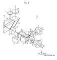
- Fig. 1 is a diagram showing an optical pickup 10 according to an embodiment of the present invention.
- the optical pickup 10 performs reproduction or recordation of information on each optical disc 30 of a BD, a DVD, or a CD with the corresponding beam light.
- the optical disc 30 is set above the optical pickup 10.
- the optical disc 30 has an outer peripheral edge 30a, an inner peripheral edge 30b, and a center 30c.
- a feeding board 21 is supported by a lead screw 41 and a guide shaft 42.
- the lead screw 41 and the guide shaft 42 are parallel in a radial direction Ra of the optical disc 30.
- a fixing unit 22 is fixed on the feeding board 21.
- An elastic member 24 made of a wire or a plate spring is attached to the fixing unit 22 parallel to a tangential direction Ta of the disc 30.
- the elastic member 24 cantilever-supports a movable unit 23.
- an arrow is given to point out one side of the tangential direction Ta and the radial direction Ra of the optical disc 30 for
- the optical axes of the objective lenses 11, 12 are parallel to the thickness direction of the optical disc 30 in a stationary state.
- the BD objective lens 11 collects the BD beam light corresponding to the BD on the BD.
- the DVD/CD objective lens 12 collects the DVD beam light corresponding to the DVD or the CD beam light corresponding to the CD on the DVD or the CD.
- the objective lenses 11, 12 are arranged in the radial direction Ra of the optical disc 30.
- a magnet 25 is attached to both side surfaces of the movable unit 23.
- a focus coil 26 and a tracking coil 27 are attached to the feeding board 21 so as to face the magnet 25.
- the magnetic force of the magnet 25 and the focus coil 26 causes the movable unit 23 and the objective lenses 11, 12 to microscopically reciprocate in the focusing direction (thickness direction of the disc 30).
- the magnetic force of the magnet 25 and the tracking coil 27 causes the movable unit 23 and the objective lenses 11, 12 to microscopically reciprocate in the tracking direction (radial direction Ra of the disc 30). That is, the movable configuration of the objective lenses 11, 12 of the optical pickup 10 is a wire suspension type or a plate spring supporting type.
- the optical pickup 10 reciprocates in the radial direction Ra of the optical disc 30 when the feeding board 21 is fed by a feeding mechanism including the lead screw 41, the guide shaft 42, and a motor and a gear group (not shown).
- Fig. 2 is a diagram showing an optical system of the optical pickup 10.
- the optical disc 30 is set above the objective lenses 11, 12.
- the DVD/CD objective lens 12 is arranged on the inner peripheral side of the optical disc 30 than the BD objective lens 11.
- a BD laser diode 1, a BD diffraction grating 2, a BD ⁇ /2 plate 3, a dichroic prism 7, and a forward scattered light detector 15 are arranged in the radial direction Ra of the optical disc 30.
- a DVD/CD laser diode 4, a DVD/CD diffraction grating 5, a DVD/CD ⁇ /2 plate 6, the dichroic prism 7, a polarization beam splitter 8, a ⁇ /4 plate 9, a collimator lens 17, and a light flux reflecting/transmitting member 16 are arranged in the tangential direction Ta of the optical disc 30.
- the light flux reflecting/transmitting member 16 and each objective lens 11, 12 are arranged in a thickness direction Th of the optical disc 30.
- the polarization beam splitter 8, a cylindrical lens 13, and a photodetector 14 are arranged in the radial direction Ra of the optical disc 30.
- the BD laser diode 1 is a light source for emitting the BD beam light corresponding to the BD.
- the DVD/CD laser diode 4 is a light source for emitting the DVD beam light corresponding to the DVD and the CD beam light corresponding to the CD.
- the BD beam light is a blue light having a wavelength of 405 nm.
- the DVD beam light is a red light having a wavelength of 650 nm.
- the CD beam light is a near infrared light having a wavelength of 780 nm. That is, the order of wavelength from the shortest side is BD beam light, the DVD beam light, and the CD beam light.
- a control unit (not shown) arranged in the optical pickup 10 makes the laser diodes 1, 4 emit either of the beam lights according to the type of the installed optical disc 30.
- the BD beam light emitted in the radial direction Ra from the BD laser diode 1 is transmitted through the BD diffraction grating 2, the BD ⁇ /2 plate 3, and the dichroic prism 7, and then entered into the polarization beam splitter 8.
- the BD beam light is divided into a main beam and a sub-beam ( ⁇ 1 order diffracted light) by the BD diffraction grating 2, and has the polarizing direction rotated by 90° by the BD ⁇ /2 plate 3 and the optical path bent to the tangential direction Ta by the dichroic prism 7.
- the scattered light of the BD beam light is received by the forward scattered light detector 15.
- the forward scattered light detector 15 converts the received scattered light to an electrical signal, detects a signal indicating the quantity of light, and outputs the signal to the control unit of the optical pickup 10.
- the control unit of the optical pickup 10 controls the drive of the BD laser diode 1 based on the light quantity signal outputted from the forward scattered light detector 15, and maintains the power of the emitting BD beam light constant.
- the DVD/CD beam light (DVD beam light or CD beam light) emitted in the tangential direction Ta from the DVD/CD laser diode 4 is transmitted through the DVD/CD diffraction grating 5, the DVD/CD ⁇ /2 plate 6, and the dichroic prism 7, and entered into the polarization beam splitter 8.
- the DVD/CD beam light is divided into a main beam and a sub-beam by the DVD/CD diffraction grating 5, and has the polarizing direction rotated by 90° by the DVD/CD ⁇ /2 plate 6.
- the optical path of the BD beam light from the BD laser diode 1 and the optical path of the DVD/CD beam light from the DVD/CD laser diode 4 coincide in the dichroic prism 7.
- the BD/DVD/CD beam light (BD beam light, DVD beam light, or CD beam light) entering the polarization beam splitter 8 from the dichroic prism 7 is transmitted through the polarization beam splitter 8, and thereafter transmitted through the ⁇ /4 plate 9 to have the polarizing direction rotated by 45°, transmitted through the collimator lens 17 to be converted to a parallel light, and entered to the light flux reflecting/transmitting member 16 in the tangential direction Ta.
- the light flux reflecting/transmitting member 16 includes one compound prism 16a.
- the optical path of the BD/DVD/CD beam light entering the light flux reflecting/transmitting member 16 is separated while being bent from the tangential direction Ta to the radial direction Ra and the thickness direction Th by the light flux reflecting/transmitting member 16, as will be described later.
- the BD beam light is then entered to the BD objective lens 11 from the light flux reflecting/transmitting member 16 and collected on the optical disc 30 of the BD by the BD objective lens 11.
- the DVD/CD beam light is entered to the DVD/CD objective lens 12 from the light flux reflecting/transmitting member 16 and collected on the optical disc 30 of the DVD or CD by the DVD/CD objective lens 12.
- the reflected light When the BD/DVD/CD beam light is reflected by a recording layer of the optical disc 30, the reflected light has the optical paths coincided while being bent from the thickness direction Th to the radial direction Ra and the tangential direction Ta by the light flux reflecting/transmitting member 16, transmitted through the collimator lens 17 and the ⁇ /4 plate 9, and entered to the polarization beam splitter 8.
- the reflected light having the optical path bent from the tangential direction Ta to the radial direction Ra by the polarization beam splitter 8 is transmitted through the cylindrical lens 13 and received by the photodetector 14.
- the photodetector 14 converts the received reflected light to an electrical signal, detects a focus error signal, a tracking error signal, a reproduction signal, and other signals related to aberration and light quantity, and outputs the signals to the control unit of the optical pickup 10.
- the focus error signal is detected through the astigmatism method.
- the tracking error signal is detected through the three beam method.
- the control unit of the optical pickup 10 performs reproduction or recordation of information on each optical disc 30 while performing focus or tracking servo based on each signal outputted from the photodetector 14.
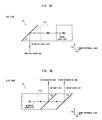
- Figs. 3A and 3B are diagrams showing the light flux reflecting/transmitting member 16.
- Fig. 3A is a top view (view seen from the objective lens 11, 12 side) of the light flux reflecting/transmitting member 16.
- Fig. 3B is a side view (view seen from the collimator lens 17 side) of the light flux reflecting/transmitting member 16.
- the optical axis of the BD/DVD/CD beam light is shown with a solid line
- the optical axis of the BD beam light is shown with a chain dashed line
- the optical axis of the DVD/CD beam light is shown with a chain double-dashed line.
- the first optical film F1 and the third optical film F3 are total reflection films for reflecting all the BD/DVD/CD beam lights.
- the second optical film F2 is a wavelength selection film for selectively reflecting or transmitting the BD/DVD/CD beam light depending on the wavelength.
- the second optical film F2 is a dichroic film, which is one example of the wavelength selection film, that reflects the BD beam light having a short wavelength and transmits the DVD/CD beam light having a long wavelength.
- the first optical film F1 is arranged at an angle of 45° with respect to the tangential direction Ta and the radial direction Ra of the optical disc 30 so as to face the collimator lens 17 ( Fig. 2 ) and the optical films F2, F3.
- the second optical film F2 and the third optical film F3 are arranged at an angle of 45° with respect to the radial direction Ra and the thickness direction Th of the optical disc 30 so as to face the first optical film F1 and each objective lens 11, 12 ( Fig. 2 ).
- the optical films F1 to F3 are arranged in the order of the first optical film F1, the second optical film F2, and the third optical film F3 in the radial direction Ra from the outer peripheral edge 30a towards the inner peripheral edge 30b of the optical disc 30.
- the BD/DVD/CD beam light exiting from the collimator lens 17 enters the compound prism 16a in the tangential direction Ta as shown with a solid line in Fig. 3A , and is reflected by the first optical film F1 to be bent by 90° in the radial direction Ra and entered to the second optical film F2 as shown in Fig. 3B .
- the BD beam light is reflected by the second optical film F2 to be bent by 90° in the thickness direction Th as shown with a chain dashed line in Fig. 3B , and entered to the BD objective lens 11.
- the DVD/CD beam light is transmitted through the second optical film F2 as shown with chain double-dashed lines in Figs.
- Fig. 6 is a list of characteristics of the optical films F1 to F3.
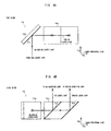
- the light flux reflecting/transmitting member 16 including one compound prism 16a is used, but in place thereof, the light flux reflecting/transmitting member 16 including one mirror 16b and one compound prism 16c may be used as shown in Figs. 4A and 4B .
- the first optical film F1 is integrally arranged on the mirror 16b.
- the second optical film F2 and the third optical film F3 are integrally arranged on the compound prism 16c.
- the configuration, function, and arrangement state of the optical films F1 to F3 are similar to the above, and thus redundant description will be omitted.
- the BD/DVD/CD beam light exiting from the collimator lens 17 enters the first optical film F1 of the mirror 16b in the tangential direction Ta as shown with a solid line in Fig. 4A , and is reflected by the first optical film F1 to be bent by 90° in the radial direction Ra and entered to the compound prism 16c and the second optical film F2 as shown in Figs. 4A and 4B .
- the BD beam light is reflected by the second optical film F2 to be bent by 90° in the thickness direction Th as shown with a chain dashed line in Fig. 4B , and entered to the BD objective lens 11.
- the DVD/CD beam light is transmitted through the second optical film F2 as shown with chain double-dashed lines in Figs.
- the third optical film F3 reflected by the third optical film F3 to be bent by 90° in the thickness direction Th and entered to the DVD/CD objective lens 12.
- the reflected light from the optical disc 30 of the BD/DVD/CD beam light enters the collimator lens 17 in the reverse order.
- the characteristics of the optical films F1 to F3 are as shown in Fig. 6 .
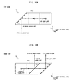
- the light flux reflecting/transmitting member 16 including three mirrors 16d to 16f may also be used as shown in Figs. 5A and 5B .
- the first optical film F1, the second optical film F2, and the third optical film F3 are each integrally arranged on the mirrors 16d to 16f.
- the configuration, function, and arrangement state of the optical films F1 to F3 are similar to the above, and thus redundant description will be omitted.
- the BD/DVD/CD beam light exiting from the collimator lens 17 enters the first optical film F1 of the mirror 16d in the tangential direction Ta as shown with a solid line in Fig.
- the BD beam light is reflected by the second optical film F2 to be bent by 90° in the thickness direction Th as shown with a chain dashed line in Fig. 5B , and entered to the BD objective lens 11.
- the DVD/CD beam light is transmitted through the second optical film F2 as shown with chain double-dashed lines in Figs. 5A and 5B , reflected by the third optical film F3 of the mirror 16f to be bent by 90° in the thickness direction Th and entered to the DVD/CD objective lens 12.
- the reflected light from the optical disc 30 of the BD/DVD/CD beam light enters the collimator lens 17 in the reverse order.
- the characteristics of the optical films F1 to F3 are as shown in Fig. 6 .
- the light flux reflecting/transmitting member 16 including one mirror 16g and one compound prism 16h may be used as shown in Figs. 7 , 8A and 8B .
- the mirror 16g and the previously described optical components 4 to 9, and 17 are arranged in the tangential direction Ta of the optical disc 30.
- the mirror 16g, the compound prism 16h, and the objective lenses 11, 12 are arranged in the thickness direction Th of the optical disc 30.
- the first optical film F1 is arranged on the mirror 16g.
- the second optical film F2 and the third optical film F3 are arranged on the compound prism 16h.
- the first optical film F1 is arranged at an angle of 45° with respect to the tangential direction Ta and the thickness direction Th of the optical disc 30 so as to face the collimator lens 17 and the second optical film F2.
- the second optical film F2 is arranged at an angle of 45° with respect to the radial direction Ra and the thickness direction Th of the optical disc 30 so as to face the first optical film F1 and the third optical film F3.
- the third optical film F3 is arranged on the inner peripheral side of the optical disc 30 than the second optical film F2 so as to be parallel to the second optical film F2 and face the second optical film F2.
- the DVD/CD objective lens 12 is arranged above (optical disc 30 side) the second optical film F2 of the compound prism 16h, and the BD objective lens 11 is arranged above the third optical film F3. That is, the objective lenses 11, 12 are arranged in the radial direction Ra of the optical disc 30 so that the BD objective lens 11 is positioned on the inner peripheral side of the optical disc 30 than the DVD/CD objective lens 12.
- the BD/DVD/CD beam light exiting from the collimator lens 17 enters the first optical film F1 of the mirror 16g in the tangential direction Ta, as shown with solid lines and broken lines in Figs.
- Fig. 9 is a list of characteristics of the optical films F1 to F3.
- the second optical film F2 for reflecting the BD beam light having a short wavelength and transmitting the DVD/CD beam light having a long wavelength is arranged on the light flux reflecting/transmitting member 16, but a second optical film F2a for transmitting the BD beam light having a short wavelength and reflecting the DVD/CD beam light having a long wavelength may be arranged in the light flux reflecting/transmitting member 16 as shown in Figs. 10A to 15 .
- the second optical film F2a is a dichroic film.
- the objective lenses 11, 12 are arranged as shown in Fig. 7 , where the DVD/CD objective lens 12 is arranged above the second optical film F2a, and the BD objective lens 11 is arranged above the third optical film F3.
- the BD/DVD/CD beam light exiting from the collimator lens 17 enters the first optical film F1 in the tangential direction Ta as shown with solid lines in Figs. 10A , 11A , and 12A , and is reflected by the first optical film F1 to be bent by 90° in the radial direction Ra and entered to the second optical film F2a as shown in Figs. 10A to 12B .
- the DVD/CD beam light is reflected by the second optical film F2a as shown with chain double-dashed lines in Figs. 10B , 11B , and 12B to be bent by 90° in the thickness direction Th, and entered to the DVD/CD objective lens 12.
- the BD beam light is transmitted through the second optical film F2a as shown with chain dashed lines in Figs. 10A to 12B , reflected by the third optical film F3 to be bent by 90° in the thickness direction Th, and entered to the BD objective lens 11.
- the reflected light from the optical disc 30 of the BD/DVD/CD beam light enters the collimator lens 17 in the reverse order.
- Fig. 13 is a list of characteristics of the optical films F1, F2a, and F3.
- the objective lenses 11, 12 are arranged as shown in Fig. 2 , where the BD objective lens 11 is arranged above the second optical film F2a, and the DVD/CD objective lens 12 is arranged above the third optical film F3.
- the BD/DVD/CD beam light exiting from the collimator lens 17 enters the first optical film F1 in the tangential direction Ta as shown with solid lines and broken lines in Figs. 14A and 14B , and is reflected by the first optical film F1 to be bent by 90° in the thickness direction Th, and entered to the second optical film F2a as shown in Fig. 14B .
- the BD beam light is transmitted through the second optical film F2a as shown with a chain dashed line in Fig. 14B , and entered to the BD objective lens 11.
- the DVD/CD beam light is reflected by the second optical film F2a as shown with chain double-dashed lines in Figs. 14A and 14B to be bent by 90° in the radial direction Ra, reflected by the third optical film F3 to be bent by 90° in the thickness direction Th, and entered to the DVD/CD objective lens 12.
- the reflected light from the optical disc 30 of the BD/DVD/CD beam light enters the collimator lens 17 in the reverse order.
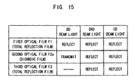
- Fig. 15 is a list of characteristics of the optical films F1, F2a, and F3.
- the optical paths of the BD/DVD/CD beam lights emitted from the laser diodes 1, 4 can be separated while being bent from the tangential direction Ta to the radial direction Ra and the thickness direction Th of the optical disc 30 by the light flux reflecting/transmitting member 16, and each beam light can be entered to the corresponding objective lens 11, 12 according to the type of optical disc 30.
- a wire suspension type or a plate spring supporting type having a relatively easy configuration and being easy to manufacture can be employed for the movable configuration of the objective lenses 11, 12, and other optical components 7 to 9, 13, 14, 16, 17, and the like can be commonly used for each objective lens 11, 12 thereby lowering the cost of the optical pickup 10.
- the first optical film F1 and the third optical film F3 of the light flux reflecting/transmitting member 16 merely reflect beam light, the configuring number of optical films F1, F3 is reduced, designing and manufacturing are facilitated, and lower cost is achieved.
- the angle in the lining direction of the spots of the main beam and the sub-beam with respect to the track of the optical disc 30 is the same for the objective lenses 11, 12 even when the three beam method, which is in principle simple and has high stability, is adopted for the method of detecting the tracking error signal, whereby the main beam and the sub-beam can all be emitted on the track of the same round with both objective lenses 11, 12, and the tracking error signal can be accurately detected.
- the objective lenses 11, 12 are arranged in the radial direction Ra of the optical disc 30, the objective lenses 11, 12 and the light flux reflecting/transmitting member 16 are arranged in the thickness direction Th of the optical disc 30, and the other optical components 4 to 9, 17, and the like are arranged in the tangential direction Ta of the optical disc 30 to allow the beam light to enter the light flux reflecting/transmitting member 16 in the tangential direction Ta of the optical disc 30, and thus the number of components to be arranged in the radial direction Ra, the thickness direction Th, and the tangential direction Ta are reduced, and miniaturization of the optical pickup 10 can be achieved.
- the occupying space in the thickness direction Th is reduced and the optical pickup 10 is further miniaturized.
- the precision and the efficiency in assembly of the light flux reflecting/transmitting member 16 can be enhanced while suppressing errors in the relative position and the relative angle of each of the optical films F1 to F3.
- the light flux reflecting/transmitting member 16 including one mirror 16b/16g integrally arranged with the first optical film F1 and one compound prism 16c/16h integrally arranged with the second optical film F2/F2a and the third optical film F3 as shown in Figs. 4A, 4B , 8A, 8B , 11A, 11B , 14A, and 14B , lower cost is achieved by using an existing mirror for the mirror 16b/16g. Furthermore, the position and the angle of attachment of the mirror 16b/16g and the compound prism 16c/16h can be independently adjusted. The precision and the efficiency in assembly of the light flux reflecting/transmitting member 16 can be enhanced while suppressing errors in the relative position and the relative angle of the second optical film F2/F2a and the third optical film F3.
- the light flux reflecting/transmitting member 16 including three mirrors 16d to 16f integrally arranged with the corresponding three optical films F1 to F3 as shown in Figs. 5A, 5B , 12A, and 12B .
- lower cost is further achieved by using an existing mirror for the mirrors 16d to 16f.
- the position and the angle of attachment of each of the mirrors 16d to 16f can be independently adjusted.
- the configuring number of optical film F2/F2a is decreased, whereby the wavefront aberration becomes smaller, designing and manufacturing are facilitated, and lower cost is further achieved.
- the configuring number of the optical film F2/F2a is further decreased by configuring the second optical film F2/F2a with dichroic film, whereby the wavefront aberration becomes smaller, designing and manufacturing are facilitated, and lower cost is further achieved.
- the number of second optical film is decreased, the wavefront aberration becomes smaller, designing and manufacturing are facilitated, and lower cost is further achieved by arranging the optical film F2 for reflecting the BD beam light as shown in Figs. 3A to 5B , 8A and 8B rather than arranging the optical film F2a for transmitting the BD beam light having a short wavelength as shown in Figs. 10A to 12B , 14A and 14B , as the second optical film on the light flux reflecting/transmitting member 16.
- the present invention may employ various modes other than the embodiment described above. For instance, an example of configuring the light flux reflecting/transmitting member with one compound prism, with one mirror and one compound prism, or with three mirrors has been described in the above embodiment, but the present invention is not limited thereto.
- the light flux reflecting/transmitting member may be configured with two mirrors and one prism, with two prisms and one mirror, or with three prisms, for example.
- the light flux reflecting/transmitting member may be configured from optical components other than the mirror and the prism.
- One laser diode 1 for emitting the BD laser light and one laser diode 4 for emitting the DVD laser light and the CD laser light has been described in the above embodiment, but the present invention is not limited thereto.
- One laser diode or the like for emitting all of the BD laser light, the DVD laser light, and the CD laser light may be used as the light source, for example.
Landscapes
- Physics & Mathematics (AREA)
- Optics & Photonics (AREA)
- Optical Head (AREA)
- Optical Recording Or Reproduction (AREA)
Abstract
Description
- The present invention relates to a structure of an optical system of an optical pickup equipped with a plurality of types of objective lenses.
- An optical pickup arranged with a plurality of types of objective lenses corresponding to BDs (Blu-ray disc; registered trademark), DVDs (Digital Versatile Disc), and CDs (Compact Disc), and the like is known (see, e.g., the below-described related art documents). This type of optical pickup emits a beam light corresponding to the type of optical disc from a light source, collects the beam light on an optical disc with an objective lens corresponding to the type of optical disc, and performs reproduction and recordation of information with respect to the optical disc. In an axial slide type optical pickup, a plurality of objective lenses is rotated about the axis to switch among the objective lenses for allowing each beam light to enter. In a wire suspension type or a plate spring supporting type optical pickup, the optical path of each beam light is separated by an optical component so that the beam light enters the corresponding objective lens.
- In
Japanese Unexamined Patent Publication No. 09-212905 Japanese Patent No. 3031220 - In
Japanese Unexamined Patent Publication No. 2005-327338 Japanese Unexamined Patent Publication No. 2006-24351 - In
Japanese Unexamined Patent Publication No. 2004-295983 - However, since a complex mechanism for rotating the objective lens is required and the rotating precision thereof must be high in the axial slide type optical pickup, thus the cost becomes high. When two types of objective lenses are arranged in the tangential direction of the optical disc as in
Japanese Patent No. 3031220 Japanese Unexamined Patent Publication No. 2005-327338 Japanese Unexamined Patent Publication No. 2004-295983 Japanese Unexamined Patent Publication No. 2004-295983 - The present invention aims to solve the above problems and to provide an optical pickup equipped with a plurality of types of objective lenses in which tracking error signals are accurately detected through a three beam method and lower cost and miniaturization are achieved.
- The present invention provides an optical pickup including: a light source for emitting a beam light corresponding to different types of optical discs; a first objective lens for collecting the beam light corresponding to one optical disc on the corresponding optical disc; and a second objective lens for collecting the beam light corresponding to another optical disc on the corresponding optical disc, the optical pickup performing at least one of reproduction and recordation of information on each optical disc with the corresponding beam light, the optical pickup further including a light flux reflecting/transmitting member arranged with a first optical film and a third optical film for reflecting the beam light, and a second optical film for reflecting or transmitting the beam light, wherein the first and second objective lenses are arranged in a radial direction of the optical disc, the light flux reflecting/transmitting member is arranged on a side opposite to the optical disc of the first and second objective lenses, and the beam light emitted from the light source is entered to the light flux reflecting/transmitting member in a tangential direction of the optical disc. The light flux reflecting/transmitting member reflects the entered beam light with the first optical film to be bent in the radial direction of the optical disc, reflects one of the beam lights with the second optical film so as to make the beam light enter the first objective lens, transmits the other beam light through the second optical film and reflects the other beam light with the third optical film so as to make the other beam light enter the second objective lens. Alternatively, the light flux reflecting/transmitting member reflects the entered beam light with the first optical film to be bent in a thickness direction of the optical disc, transmits one of the beam lights through the second optical film so as to make the beam light enter the first objective lens, reflects the other beam light with the second optical film to be bent in the radial direction of the optical disc, and reflects the other beam light with the third optical film so as to make the other beam light enter the second objective lens.
- According to this, the optical paths of each beam light emitted from the light source can be separated while being bent from the tangential direction to the radial direction and the thickness direction of the optical disc by the light flux reflecting/transmitting member, and each beam light can be entered to the corresponding objective lens according to the type of the optical disc. Thus, a wire suspension type or a plate spring supporting type having a relatively easy configuration and being easy to manufacture can be employed for the movable configuration of the objective lenses, and other optical components can be commonly used for each objective lens, thereby lowering the cost of the optical pickup. Furthermore, since the first and the third optical films of the light flux reflecting/transmitting member merely reflect the beam light, the configuring number of optical films is reduced, designing and manufacturing are facilitated, and lower cost is achieved. Since the two types of objective lenses are arranged in the radial direction of the optical disc, the angle in the lining direction of the spots of the main beam and the sub-beam with respect to the track of the optical disc is the same for both objective lenses even when the three beam method, which is in principle simple and has high stability, is adopted for the method of detecting the tracking error signal, whereby the main beam and the sub-beam can all be emitted on the track of the same round with both objective lenses, and the tracking error signal can be accurately detected. Moreover, the objective lenses are arranged in the radial direction of the optical disc, the objective lenses and the light flux reflecting/transmitting member are arranged in the thickness direction of the optical disc, and the other optical components are arranged in the tangential direction of the optical disc to allow the beam light to enter to the light flux reflecting/transmitting member in the tangential direction of the optical disc, and thus the number of components to be arranged in the radial direction, the thickness direction, and the tangential direction are reduced, and miniaturization of the optical pickup can be achieved. In the case of the light flux reflecting/transmitting member for bending the optical path of each beam light from the tangential direction to the radial direction with the first optical film, the occupying space in the thickness direction is reduced, and the optical pickup is further miniaturized.
- According to the present invention, in the optical pickup, the light flux reflecting/transmitting member may include one compound prism integrally arranged with the first, the second, and the third optical films. Thus, the precision and the efficiency in assembly of the light flux reflecting/transmitting member can be enhanced while suppressing errors in the relative position and the relative angle of each optical film.
- According to the present invention, in the optical pickup, the light flux reflecting/transmitting member may include one mirror integrally arranged with the first optical film and one compound prism integrally arranged with the second and the third optical films. Therefore, lower cost is achieved by using an existing mirror. Furthermore, the position and the angle of attachment of the mirror and the compound prism can be independently adjusted. The precision and the efficiency in assembly of the light flux reflecting/transmitting member can be enhanced while suppressing errors in the relative position and the relative angle of the second and the third optical films.
- According to the present invention, in the optical pickup, the light flux reflecting/transmitting member may include three mirrors integrally arranged with the first, the second, and the third optical film, respectively. Therefore, lower cost is achieved by using an existing mirror. Furthermore, the position and the angle of attachment of each mirror can be independently adjusted.
- According to the present invention, in the optical pickup, the second optical film of the light flux reflecting/transmitting member may include a wavelength selection film for selectively reflecting or transmitting each beam light according to its wavelength. When separating the optical paths of the beam lights through polarization as in
Japanese Unexamined Patent Publication No. 09-212905 Japanese Patent No. 3031220 Japanese Unexamined Patent Publication No. 2006-24351 - According to the present invention, in the optical pickup, the light source may emit a first beam light having a first wavelength, a second beam light having a second wavelength longer than the first wavelength, and a third beam light having a third wavelength longer than the second wavelength. The second optical film of the light flux reflecting/transmitting member may reflect the first beam light and transmits the second and third beam lights. Alternatively, the second optical film of the light flux reflecting/transmitting member may transmit the first beam light and reflects the second and third beam lights. According to these, the first beam light and the second and third beam lights are separated to reflection beam light and transmission beam light according to the wavelengths by the second optical film, and respectively entered to the corresponding objective lenses. When the optical film for reflecting the first beam light is arranged rather than the optical film for transmitting the first beam light having a short wavelength, for the second optical film in the light flux reflecting/transmitting member, the number of second optical film decreases, the wavefront aberration becomes smaller, designing and manufacturing are facilitated, and lowering in cost is further achieved.
- According to a typical embodiment of the present invention, the optical pickup including: a light source for emitting a first beam light corresponding to a BD, a second beam light corresponding to a DVD, and a third beam light corresponding to a CD; a first objective lens for collecting the first beam light on the BD; and a second objective lens for collecting the second or the third beam light on the DVD or the CD, the optical pickup performing at least one of reproduction and recordation of information on each optical disc with the corresponding beam light, the optical pickup further including a light flux reflecting/transmitting member including one compound prism integrally arranged with a first optical film, a second optical film, and a third optical film, wherein the first and third optical films include a total reflection film for reflecting the beam light, the second optical film includes a dichroic film for selectively reflecting or transmitting the beam light according to its wavelength, the first and second objective lenses are arranged in a radial direction of the optical disc, the light flux reflecting/transmitting member is arranged on a side opposite to the optical disc of the first and second objective lenses, and the beam light emitted from the light source is entered to the light flux reflecting/transmitting member in a tangential direction of the optical disc. The light flux reflecting/transmitting member reflects the entered beam light with the first optical film to be bent in the radial direction of the optical disc, reflects the first beam light with the second optical film so as to make the first beam light enter the first objective lens, transmits the second or third beam light through the second optical film, and reflects the second or third beam light with the third optical film so as to make the second or third beam light enter the second objective lens. Alternatively, the light flux reflecting/transmitting member may include one mirror integrally arranged with a first optical film and one compound prism integrally arranged with a second optical film and a third optical film, reflects the entered beam light with the first optical film to be bent in a thickness direction of the optical disc, transmits the second or the third beam light with the second optical film so as to make the second or third beam light enter the second objective lens, reflects the first beam light with the second optical film to be bent in the radial direction of the optical disc, and reflects the first beam light with the third optical film so as to make the first beam light enter the first objective lens.
- According to this, the tracking error signal can be accurately detected through the three beam method with each objective lens, and lowering in cost and miniaturization of the optical pickup can be achieved. Furthermore, the precision and the efficiency in assembly of the light flux reflecting/transmitting member can be enhanced by using the light flux reflecting/transmitting member including one compound prism. By using the light flux reflecting/transmitting member including one mirror and one compound prism, lower cost can be achieved by using an existing mirror, the position and the angle of attachment of the mirror and the compound prism can be independently adjusted, and the precision and the efficiency in assembly of the light flux reflecting/transmitting member can be enhanced. Moreover, since the first and third optical films of the light flux reflecting/transmitting member include a total reflection film, and the second optical film includes a dichroic film for reflecting the first beam light of a short wavelength, the configuring number of each optical film is decreased, the wavefront aberration becomes smaller, designing and manufacturing are facilitated, and lowering in cost is further achieved.
- According to the present invention, the tracking error signal is accurately detected through the three beam method and lowering in cost and miniaturization are achieved in the optical pickup equipped with a plurality of types of objective lenses.
-
-
Fig. 1 is a diagram showing an optical pickup; -
Fig. 2 is a diagram showing an optical system of the optical pickup; -
Figs. 3A and 3B are diagrams showing a light flux reflecting/transmitting member; -
Figs. 4A and 4B are diagrams showing another light flux reflecting/transmitting member; -
Figs. 5A and 5B are diagrams showing another light flux reflecting/transmitting member; -
Fig. 6 is a diagram showing characteristics of films of the light flux reflecting/transmitting member; -
Fig. 7 is a diagram showing another optical system of an optical pickup; -
Figs. 8A and 8B are diagrams showing another light flux reflecting/transmitting member; -
Fig. 9 is a diagram showing characteristics of films of another light flux reflecting/transmitting member; -
Figs. 10A and 10B are diagrams showing another light flux reflecting/transmitting member; -
Figs. 11A and 11B are diagrams showing another light flux reflecting/transmitting member; -
Figs. 12A and 12B are diagrams showing another light flux reflecting/transmitting member; -
Fig. 13 is a diagram showing characteristics of films of another light flux reflecting/transmitting member; -
Figs. 14A and 14B are diagrams showing another light flux reflecting/transmitting member; and -
Fig. 15 is a diagram showing characteristics of films of another light flux reflecting/transmitting member. -
Fig. 1 is a diagram showing anoptical pickup 10 according to an embodiment of the present invention. Theoptical pickup 10 performs reproduction or recordation of information on eachoptical disc 30 of a BD, a DVD, or a CD with the corresponding beam light. Theoptical disc 30 is set above theoptical pickup 10. Theoptical disc 30 has an outerperipheral edge 30a, an innerperipheral edge 30b, and acenter 30c. A feedingboard 21 is supported by alead screw 41 and aguide shaft 42. Thelead screw 41 and theguide shaft 42 are parallel in a radial direction Ra of theoptical disc 30. A fixingunit 22 is fixed on the feedingboard 21. Anelastic member 24 made of a wire or a plate spring is attached to the fixingunit 22 parallel to a tangential direction Ta of thedisc 30. Theelastic member 24 cantilever-supports amovable unit 23. In the figure, an arrow is given to point out one side of the tangential direction Ta and the radial direction Ra of theoptical disc 30 for the sake of convenience. - Two types of
objective lenses movable unit 23. The optical axes of theobjective lenses optical disc 30 in a stationary state. The BDobjective lens 11 collects the BD beam light corresponding to the BD on the BD. The DVD/CDobjective lens 12 collects the DVD beam light corresponding to the DVD or the CD beam light corresponding to the CD on the DVD or the CD. Theobjective lenses optical disc 30. - A
magnet 25 is attached to both side surfaces of themovable unit 23. Afocus coil 26 and a trackingcoil 27 are attached to the feedingboard 21 so as to face themagnet 25. The magnetic force of themagnet 25 and thefocus coil 26 causes themovable unit 23 and theobjective lenses magnet 25 and the trackingcoil 27 causes themovable unit 23 and theobjective lenses objective lenses optical pickup 10 is a wire suspension type or a plate spring supporting type. Theoptical pickup 10 reciprocates in the radial direction Ra of theoptical disc 30 when the feedingboard 21 is fed by a feeding mechanism including thelead screw 41, theguide shaft 42, and a motor and a gear group (not shown). -
Fig. 2 is a diagram showing an optical system of theoptical pickup 10. Although not shown, theoptical disc 30 is set above theobjective lenses objective lens 12 is arranged on the inner peripheral side of theoptical disc 30 than the BDobjective lens 11. ABD laser diode 1, aBD diffraction grating 2, a BD λ/2plate 3, adichroic prism 7, and a forward scatteredlight detector 15 are arranged in the radial direction Ra of theoptical disc 30. A DVD/CD laser diode 4, a DVD/CD diffraction grating 5, a DVD/CD λ/2plate 6, thedichroic prism 7, apolarization beam splitter 8, a λ/4 plate 9, acollimator lens 17, and a light flux reflecting/transmittingmember 16 are arranged in the tangential direction Ta of theoptical disc 30. The light flux reflecting/transmittingmember 16 and eachobjective lens optical disc 30. Thepolarization beam splitter 8, acylindrical lens 13, and aphotodetector 14 are arranged in the radial direction Ra of theoptical disc 30. - The
BD laser diode 1 is a light source for emitting the BD beam light corresponding to the BD. The DVD/CD laser diode 4 is a light source for emitting the DVD beam light corresponding to the DVD and the CD beam light corresponding to the CD. The BD beam light is a blue light having a wavelength of 405 nm. The DVD beam light is a red light having a wavelength of 650 nm. The CD beam light is a near infrared light having a wavelength of 780 nm. That is, the order of wavelength from the shortest side is BD beam light, the DVD beam light, and the CD beam light. A control unit (not shown) arranged in theoptical pickup 10 makes thelaser diodes 1, 4 emit either of the beam lights according to the type of the installedoptical disc 30. - As shown with a chain dashed line, the BD beam light emitted in the radial direction Ra from the
BD laser diode 1 is transmitted through theBD diffraction grating 2, the BD λ/2plate 3, and thedichroic prism 7, and then entered into thepolarization beam splitter 8. In this case, the BD beam light is divided into a main beam and a sub-beam (± 1 order diffracted light) by theBD diffraction grating 2, and has the polarizing direction rotated by 90° by the BD λ/2plate 3 and the optical path bent to the tangential direction Ta by thedichroic prism 7. The scattered light of the BD beam light is received by the forward scatteredlight detector 15. The forward scatteredlight detector 15 converts the received scattered light to an electrical signal, detects a signal indicating the quantity of light, and outputs the signal to the control unit of theoptical pickup 10. The control unit of theoptical pickup 10 controls the drive of theBD laser diode 1 based on the light quantity signal outputted from the forward scatteredlight detector 15, and maintains the power of the emitting BD beam light constant. - As shown with a chain double-dashed line, the DVD/CD beam light (DVD beam light or CD beam light) emitted in the tangential direction Ta from the DVD/CD laser diode 4 is transmitted through the DVD/
CD diffraction grating 5, the DVD/CD λ/2plate 6, and thedichroic prism 7, and entered into thepolarization beam splitter 8. In this case, the DVD/CD beam light is divided into a main beam and a sub-beam by the DVD/CD diffraction grating 5, and has the polarizing direction rotated by 90° by the DVD/CD λ/2plate 6. The optical path of the BD beam light from theBD laser diode 1 and the optical path of the DVD/CD beam light from the DVD/CD laser diode 4 coincide in thedichroic prism 7. - The BD/DVD/CD beam light (BD beam light, DVD beam light, or CD beam light) entering the
polarization beam splitter 8 from thedichroic prism 7 is transmitted through thepolarization beam splitter 8, and thereafter transmitted through the λ/4 plate 9 to have the polarizing direction rotated by 45°, transmitted through thecollimator lens 17 to be converted to a parallel light, and entered to the light flux reflecting/transmittingmember 16 in the tangential direction Ta. The light flux reflecting/transmittingmember 16 includes onecompound prism 16a. The optical path of the BD/DVD/CD beam light entering the light flux reflecting/transmittingmember 16 is separated while being bent from the tangential direction Ta to the radial direction Ra and the thickness direction Th by the light flux reflecting/transmittingmember 16, as will be described later. The BD beam light is then entered to the BDobjective lens 11 from the light flux reflecting/transmittingmember 16 and collected on theoptical disc 30 of the BD by the BDobjective lens 11. The DVD/CD beam light is entered to the DVD/CDobjective lens 12 from the light flux reflecting/transmittingmember 16 and collected on theoptical disc 30 of the DVD or CD by the DVD/CDobjective lens 12. - When the BD/DVD/CD beam light is reflected by a recording layer of the
optical disc 30, the reflected light has the optical paths coincided while being bent from the thickness direction Th to the radial direction Ra and the tangential direction Ta by the light flux reflecting/transmittingmember 16, transmitted through thecollimator lens 17 and the λ/4 plate 9, and entered to thepolarization beam splitter 8. The reflected light having the optical path bent from the tangential direction Ta to the radial direction Ra by thepolarization beam splitter 8 is transmitted through thecylindrical lens 13 and received by thephotodetector 14. Thephotodetector 14 converts the received reflected light to an electrical signal, detects a focus error signal, a tracking error signal, a reproduction signal, and other signals related to aberration and light quantity, and outputs the signals to the control unit of theoptical pickup 10. The focus error signal is detected through the astigmatism method. The tracking error signal is detected through the three beam method. The control unit of theoptical pickup 10 performs reproduction or recordation of information on eachoptical disc 30 while performing focus or tracking servo based on each signal outputted from thephotodetector 14. -
Figs. 3A and 3B are diagrams showing the light flux reflecting/transmittingmember 16. Specifically,Fig. 3A is a top view (view seen from theobjective lens member 16.Fig. 3B is a side view (view seen from thecollimator lens 17 side) of the light flux reflecting/transmittingmember 16. InFigs. 3A and 3B , the optical axis of the BD/DVD/CD beam light is shown with a solid line, the optical axis of the BD beam light is shown with a chain dashed line, and the optical axis of the DVD/CD beam light is shown with a chain double-dashed line. This is the same inFig. 2 described above, as well asFigs. 4A to 5B ,7 to 8B ,10A to 12B ,14A and 14B to be described later. - Three optical films F1 to F3 are integrally arranged on a
compound prism 16a configuring the light flux reflecting/transmittingmember 16. The first optical film F1 and the third optical film F3 are total reflection films for reflecting all the BD/DVD/CD beam lights. The second optical film F2 is a wavelength selection film for selectively reflecting or transmitting the BD/DVD/CD beam light depending on the wavelength. Specifically, the second optical film F2 is a dichroic film, which is one example of the wavelength selection film, that reflects the BD beam light having a short wavelength and transmits the DVD/CD beam light having a long wavelength. The first optical film F1 is arranged at an angle of 45° with respect to the tangential direction Ta and the radial direction Ra of theoptical disc 30 so as to face the collimator lens 17 (Fig. 2 ) and the optical films F2, F3. The second optical film F2 and the third optical film F3 are arranged at an angle of 45° with respect to the radial direction Ra and the thickness direction Th of theoptical disc 30 so as to face the first optical film F1 and eachobjective lens 11, 12 (Fig. 2 ). The optical films F1 to F3 are arranged in the order of the first optical film F1, the second optical film F2, and the third optical film F3 in the radial direction Ra from the outerperipheral edge 30a towards the innerperipheral edge 30b of theoptical disc 30. - The BD/DVD/CD beam light exiting from the
collimator lens 17 enters thecompound prism 16a in the tangential direction Ta as shown with a solid line inFig. 3A , and is reflected by the first optical film F1 to be bent by 90° in the radial direction Ra and entered to the second optical film F2 as shown inFig. 3B . The BD beam light is reflected by the second optical film F2 to be bent by 90° in the thickness direction Th as shown with a chain dashed line inFig. 3B , and entered to the BDobjective lens 11. The DVD/CD beam light is transmitted through the second optical film F2 as shown with chain double-dashed lines inFigs. 3A and 3B , reflected by the third optical film F3 to be bent by 90° in the thickness direction Th and entered to the DVD/CDobjective lens 12. The reflected light from theoptical disc 30 of the BD/DVD/CD beam light enters thecollimator lens 17 in the reverse order.Fig. 6 is a list of characteristics of the optical films F1 to F3. - In the above embodiment, the light flux reflecting/transmitting
member 16 including onecompound prism 16a is used, but in place thereof, the light flux reflecting/transmittingmember 16 including onemirror 16b and onecompound prism 16c may be used as shown inFigs. 4A and 4B . The first optical film F1 is integrally arranged on themirror 16b. The second optical film F2 and the third optical film F3 are integrally arranged on thecompound prism 16c. The configuration, function, and arrangement state of the optical films F1 to F3 are similar to the above, and thus redundant description will be omitted. The BD/DVD/CD beam light exiting from thecollimator lens 17 enters the first optical film F1 of themirror 16b in the tangential direction Ta as shown with a solid line inFig. 4A , and is reflected by the first optical film F1 to be bent by 90° in the radial direction Ra and entered to thecompound prism 16c and the second optical film F2 as shown inFigs. 4A and 4B . The BD beam light is reflected by the second optical film F2 to be bent by 90° in the thickness direction Th as shown with a chain dashed line inFig. 4B , and entered to the BDobjective lens 11. The DVD/CD beam light is transmitted through the second optical film F2 as shown with chain double-dashed lines inFigs. 4A and 4B , reflected by the third optical film F3 to be bent by 90° in the thickness direction Th and entered to the DVD/CDobjective lens 12. The reflected light from theoptical disc 30 of the BD/DVD/CD beam light enters thecollimator lens 17 in the reverse order. The characteristics of the optical films F1 to F3 are as shown inFig. 6 . - The light flux reflecting/transmitting
member 16 including threemirrors 16d to 16f may also be used as shown inFigs. 5A and 5B . The first optical film F1, the second optical film F2, and the third optical film F3 are each integrally arranged on themirrors 16d to 16f. The configuration, function, and arrangement state of the optical films F1 to F3 are similar to the above, and thus redundant description will be omitted. The BD/DVD/CD beam light exiting from thecollimator lens 17 enters the first optical film F1 of themirror 16d in the tangential direction Ta as shown with a solid line inFig. 5A , and is reflected by the first optical film F1 to be bent by 90° in the radial direction Ra and entered to the second optical film F2 of themirror 16e as shown inFigs. 5A and 5B . The BD beam light is reflected by the second optical film F2 to be bent by 90° in the thickness direction Th as shown with a chain dashed line inFig. 5B , and entered to the BDobjective lens 11. The DVD/CD beam light is transmitted through the second optical film F2 as shown with chain double-dashed lines inFigs. 5A and 5B , reflected by the third optical film F3 of the mirror 16f to be bent by 90° in the thickness direction Th and entered to the DVD/CDobjective lens 12. The reflected light from theoptical disc 30 of the BD/DVD/CD beam light enters thecollimator lens 17 in the reverse order. The characteristics of the optical films F1 to F3 are as shown inFig. 6 . - Furthermore, the light flux reflecting/transmitting
member 16 including onemirror 16g and onecompound prism 16h may be used as shown inFigs. 7 ,8A and 8B . Themirror 16g and the previously described optical components 4 to 9, and 17 are arranged in the tangential direction Ta of theoptical disc 30. Themirror 16g, thecompound prism 16h, and theobjective lenses optical disc 30. The first optical film F1 is arranged on themirror 16g. The second optical film F2 and the third optical film F3 are arranged on thecompound prism 16h. The first optical film F1 is arranged at an angle of 45° with respect to the tangential direction Ta and the thickness direction Th of theoptical disc 30 so as to face thecollimator lens 17 and the second optical film F2. The second optical film F2 is arranged at an angle of 45° with respect to the radial direction Ra and the thickness direction Th of theoptical disc 30 so as to face the first optical film F1 and the third optical film F3. The third optical film F3 is arranged on the inner peripheral side of theoptical disc 30 than the second optical film F2 so as to be parallel to the second optical film F2 and face the second optical film F2. The configuration and the function of the optical films F1 to F3 are similar to the above, and thus redundant description will be omitted. - In the above case, as shown in
Fig. 7 , the DVD/CDobjective lens 12 is arranged above (optical disc 30 side) the second optical film F2 of thecompound prism 16h, and the BDobjective lens 11 is arranged above the third optical film F3. That is, theobjective lenses optical disc 30 so that the BDobjective lens 11 is positioned on the inner peripheral side of theoptical disc 30 than the DVD/CDobjective lens 12. Thus, the BD/DVD/CD beam light exiting from thecollimator lens 17 enters the first optical film F1 of themirror 16g in the tangential direction Ta, as shown with solid lines and broken lines inFigs. 8A and 8B , and is reflected by the first optical film F1 to be bent by 90° in the thickness direction Th and entered to the second optical film F2 of thecompound prism 16h, as shown inFig. 8B . The DVD/CD beam light is transmitted through the second optical film F2 as shown with a chain double-dashed line inFig. 8B , and entered to the DVD/CDobjective lens 12. The BD beam light is reflected by the second optical film F2 to be bent by 90° in the radial direction Ra as shown with chain dashed lines inFigs. 8A and 8B , reflected by the third optical film F3 of thecompound prism 16h to be bent by 90° in the thickness direction Th, and entered to the BDobjective lens 11. The reflected light from theoptical disc 30 of the BD/DVD/CD beam light enters thecollimator lens 17 in the reverse order.Fig. 9 is a list of characteristics of the optical films F1 to F3. - In the above description, the second optical film F2 for reflecting the BD beam light having a short wavelength and transmitting the DVD/CD beam light having a long wavelength is arranged on the light flux reflecting/transmitting
member 16, but a second optical film F2a for transmitting the BD beam light having a short wavelength and reflecting the DVD/CD beam light having a long wavelength may be arranged in the light flux reflecting/transmittingmember 16 as shown inFigs. 10A to 15 . The second optical film F2a is a dichroic film. - When the second optical film F2a is arranged on the
compound prism 16a as shown inFigs. 10A and 10B , when the second optical film F2a is arranged on thecompound prism 16c as shown inFigs. 11A and 11B , or when the second optical film F2a is arranged on themirror 16e as shown inFigs. 12A and 12B , theobjective lenses Fig. 7 , where the DVD/CDobjective lens 12 is arranged above the second optical film F2a, and the BDobjective lens 11 is arranged above the third optical film F3. Thus, the BD/DVD/CD beam light exiting from thecollimator lens 17 enters the first optical film F1 in the tangential direction Ta as shown with solid lines inFigs. 10A ,11A , and12A , and is reflected by the first optical film F1 to be bent by 90° in the radial direction Ra and entered to the second optical film F2a as shown inFigs. 10A to 12B . The DVD/CD beam light is reflected by the second optical film F2a as shown with chain double-dashed lines inFigs. 10B ,11B , and12B to be bent by 90° in the thickness direction Th, and entered to the DVD/CDobjective lens 12. The BD beam light is transmitted through the second optical film F2a as shown with chain dashed lines inFigs. 10A to 12B , reflected by the third optical film F3 to be bent by 90° in the thickness direction Th, and entered to the BDobjective lens 11. The reflected light from theoptical disc 30 of the BD/DVD/CD beam light enters thecollimator lens 17 in the reverse order.Fig. 13 is a list of characteristics of the optical films F1, F2a, and F3. - When the second optical film F2a is arranged on the
compound prism 16h as shown inFigs. 14A and 14B , theobjective lenses Fig. 2 , where the BDobjective lens 11 is arranged above the second optical film F2a, and the DVD/CDobjective lens 12 is arranged above the third optical film F3. Thus, the BD/DVD/CD beam light exiting from thecollimator lens 17 enters the first optical film F1 in the tangential direction Ta as shown with solid lines and broken lines inFigs. 14A and 14B , and is reflected by the first optical film F1 to be bent by 90° in the thickness direction Th, and entered to the second optical film F2a as shown inFig. 14B . The BD beam light is transmitted through the second optical film F2a as shown with a chain dashed line inFig. 14B , and entered to the BDobjective lens 11. The DVD/CD beam light is reflected by the second optical film F2a as shown with chain double-dashed lines inFigs. 14A and 14B to be bent by 90° in the radial direction Ra, reflected by the third optical film F3 to be bent by 90° in the thickness direction Th, and entered to the DVD/CDobjective lens 12. The reflected light from theoptical disc 30 of the BD/DVD/CD beam light enters thecollimator lens 17 in the reverse order.Fig. 15 is a list of characteristics of the optical films F1, F2a, and F3. - According to the above embodiment, the optical paths of the BD/DVD/CD beam lights emitted from the
laser diodes 1, 4 can be separated while being bent from the tangential direction Ta to the radial direction Ra and the thickness direction Th of theoptical disc 30 by the light flux reflecting/transmittingmember 16, and each beam light can be entered to the correspondingobjective lens optical disc 30. Thus, a wire suspension type or a plate spring supporting type having a relatively easy configuration and being easy to manufacture can be employed for the movable configuration of theobjective lenses optical components 7 to 9, 13, 14, 16, 17, and the like can be commonly used for eachobjective lens optical pickup 10. Furthermore, since the first optical film F1 and the third optical film F3 of the light flux reflecting/transmittingmember 16 merely reflect beam light, the configuring number of optical films F1, F3 is reduced, designing and manufacturing are facilitated, and lower cost is achieved. - Since the two types of
objective lenses optical disc 30, the angle in the lining direction of the spots of the main beam and the sub-beam with respect to the track of theoptical disc 30 is the same for theobjective lenses objective lenses - The
objective lenses optical disc 30, theobjective lenses member 16 are arranged in the thickness direction Th of theoptical disc 30, and the other optical components 4 to 9, 17, and the like are arranged in the tangential direction Ta of theoptical disc 30 to allow the beam light to enter the light flux reflecting/transmittingmember 16 in the tangential direction Ta of theoptical disc 30, and thus the number of components to be arranged in the radial direction Ra, the thickness direction Th, and the tangential direction Ta are reduced, and miniaturization of theoptical pickup 10 can be achieved. In the case of the light flux reflecting/transmittingmember 16 for bending the optical path of each beam light from the tangential direction Ta to the radial direction Ra with the first optical film F1 as shown inFigs. 3A to 5B andFigs. 10A to 12B , the occupying space in the thickness direction Th is reduced and theoptical pickup 10 is further miniaturized. - Through the use of the light flux reflecting/transmitting
member 16 including onecompound prism 16a integrally arranged with all the three optical films F1 to F3 as shown inFigs. 3A, 3B ,10A and 10B , the precision and the efficiency in assembly of the light flux reflecting/transmittingmember 16 can be enhanced while suppressing errors in the relative position and the relative angle of each of the optical films F1 to F3. - Through the use of the light flux reflecting/transmitting
member 16 including onemirror 16b/16g integrally arranged with the first optical film F1 and onecompound prism 16c/16h integrally arranged with the second optical film F2/F2a and the third optical film F3 as shown inFigs. 4A, 4B ,8A, 8B ,11A, 11B ,14A, and 14B , lower cost is achieved by using an existing mirror for themirror 16b/16g. Furthermore, the position and the angle of attachment of themirror 16b/16g and thecompound prism 16c/16h can be independently adjusted. The precision and the efficiency in assembly of the light flux reflecting/transmittingmember 16 can be enhanced while suppressing errors in the relative position and the relative angle of the second optical film F2/F2a and the third optical film F3. - Furthermore, through the use of the light flux reflecting/transmitting
member 16 including threemirrors 16d to 16f integrally arranged with the corresponding three optical films F1 to F3 as shown inFigs. 5A, 5B ,12A, and 12B , lower cost is further achieved by using an existing mirror for themirrors 16d to 16f. Additionally, the position and the angle of attachment of each of themirrors 16d to 16f can be independently adjusted. - In the case of separating the optical paths of the beam lights through polarization as in
Japanese Unexamined Patent Publication No. 09-212905 Japanese Patent No. 3031220 Japanese Unexamined Patent Publication No. 2006-24351 member 16 as described above, the configuring number of optical film F2/F2a is decreased, whereby the wavefront aberration becomes smaller, designing and manufacturing are facilitated, and lower cost is further achieved. In particular, the configuring number of the optical film F2/F2a is further decreased by configuring the second optical film F2/F2a with dichroic film, whereby the wavefront aberration becomes smaller, designing and manufacturing are facilitated, and lower cost is further achieved. - The number of second optical film is decreased, the wavefront aberration becomes smaller, designing and manufacturing are facilitated, and lower cost is further achieved by arranging the optical film F2 for reflecting the BD beam light as shown in
Figs. 3A to 5B ,8A and 8B rather than arranging the optical film F2a for transmitting the BD beam light having a short wavelength as shown inFigs. 10A to 12B ,14A and 14B , as the second optical film on the light flux reflecting/transmittingmember 16. - The present invention may employ various modes other than the embodiment described above. For instance, an example of configuring the light flux reflecting/transmitting member with one compound prism, with one mirror and one compound prism, or with three mirrors has been described in the above embodiment, but the present invention is not limited thereto. The light flux reflecting/transmitting member may be configured with two mirrors and one prism, with two prisms and one mirror, or with three prisms, for example. Alternatively, the light flux reflecting/transmitting member may be configured from optical components other than the mirror and the prism.
- An example of using one
laser diode 1 for emitting the BD laser light and one laser diode 4 for emitting the DVD laser light and the CD laser light as the light source has been described in the above embodiment, but the present invention is not limited thereto. One laser diode or the like for emitting all of the BD laser light, the DVD laser light, and the CD laser light may be used as the light source, for example. Furthermore, it is possible to use a light source of one or a plurality of laser diodes or the like for emitting two types of or four or more types of laser lights corresponding to two types of or four or more types of optical discs. - An example of applying the present invention to an optical pickup capable of performing reproduction and recordation of information for three types of optical discs of BD, DVD, and CD has been described in the above embodiment, but the present invention can be applied to an optical pickup capable of performing reproduction and recordation of information for at least two or more types out of optical discs of BD, DVD, CD, or other optical discs.
Claims (11)
- An optical pickup comprising:a light source for emitting a beam light corresponding to different types of optical discs;a first objective lens for collecting the beam light corresponding to one optical disc on the corresponding optical disc; anda second objective lens for collecting the beam light corresponding to another optical disc on the corresponding optical disc, the optical pickup performing at least one of reproduction and recordation of information on each optical disc with the corresponding beam light, the optical pickup further comprising:a light flux reflecting/transmitting member arranged with a first optical film and a third optical film for reflecting the beam light, and a second optical film for reflecting or transmitting the beam light, whereinthe first and second objective lenses are arranged in a radial direction of the optical disc,the light flux reflecting/transmitting member is arranged on a side opposite to the optical disc of the first and second objective lenses,the beam light emitted from the light source is entered to the light flux reflecting/transmitting member in a tangential direction of the optical disc, andthe light flux reflecting/transmitting member reflects the entered beam light with the first optical film to be bent in the radial direction of the optical disc, reflects one of the beam lights with the second optical film so as to make the beam light enter the first objective lens, transmits the other beam light through the second optical film and reflects the other beam light with the third optical film so as to make the other beam light enter the second objective lens.
- The optical pickup according to claim 1, wherein the light flux reflecting/transmitting member includes one compound prism integrally arranged with the first, the second, and the third optical films.
- The optical pickup according to claim 1, wherein the light flux reflecting/transmitting member includes one mirror integrally arranged with the first optical film and one compound prism integrally arranged with the second and the third optical films.
- The optical pickup according to claim 1, wherein the light flux reflecting/transmitting member includes three mirrors integrally arranged with the first, the second, and the third optical films, respectively.
- An optical pickup comprising:a light source for emitting a beam light corresponding to different types of optical discs;a first objective lens for collecting the beam light corresponding to one optical disc on the corresponding optical disc; anda second objective lens for collecting the beam light corresponding to another optical disc on the corresponding optical disc, the optical pickup performing at least one of reproduction and recordation of information on each optical disc with the corresponding beam light, the optical pickup further comprising:a light flux reflecting/transmitting member arranged with a first optical film and a third optical film for reflecting the beam light, and a second optical film for reflecting or transmitting the beam light, whereinthe first and second objective lenses are arranged in a radial direction of the optical disc,the light flux reflecting/transmitting member is arranged on a side opposite to the optical disc of the first and second objective lenses,the beam light emitted from the light source is entered to the light flux reflecting/transmitting member in a tangential direction of the optical disc, andthe light flux reflecting/transmitting member reflects the entered beam light with the first optical film to be bent in a thickness direction of the optical disc, transmits one of the beam lights through the second optical film so as to make the beam light enter the first objective lens, reflects the other beam light with the second optical film to be bent in the radial direction of the optical disc, and reflects the other beam light with the third optical film so as to make the other beam light enter the second objective lens.
- The optical pickup according to claim 5, wherein the light flux reflecting/transmitting member includes one mirror integrally arranged with the first optical film and one compound prism integrally arranged with the second and the third optical films.
- The optical pickup according to any one of claims 1 to 6, wherein
the second optical film of the light flux reflecting/transmitting member includes a wavelength selection film for selectively reflecting or transmitting each beam light according to its wavelength. - The optical pickup according to claim 7, wherein
the light source emits a first beam light having a first wavelength, a second beam light having a second wavelength longer than the first wavelength, and a third beam light having a third wavelength longer than the second wavelength, and
the second optical film of the light flux reflecting/transmitting member reflects the first beam light and transmits the second and third beam lights. - The optical pickup according to claim 7, wherein
the light source emits a first beam light having a first wavelength, a second beam light having a second wavelength longer than the first wavelength, and a third beam light having a third wavelength longer than the second wavelength, and
the second optical film of the light flux reflecting/transmitting member transmits the first beam light and reflects the second and third beam lights. - An optical pickup comprising:a light source for emitting a first beam light corresponding to a BD, a second beam light corresponding to a DVD, and a third beam light corresponding to a CD;a first objective lens for collecting the first beam light on the BD; anda second objective lens for collecting the second or the third beam light on the DVD or the CD, the optical pickup performing at least one of reproduction and recordation of information on each optical disc with the corresponding beam light, the optical pickup further comprising:a light flux reflecting/transmitting member including one compound prism integrally arranged with a first optical film, a second optical film, and a third optical film, whereinthe first and third optical films include a total reflection film for reflecting the beam light,the second optical film includes a dichroic film for selectively reflecting or transmitting the beam light according to its wavelength,the first and second objective lenses are arranged in a radial direction of the optical disc,the light flux reflecting/transmitting member is arranged on a side opposite to the optical disc of the first and second objective lenses,the beam light emitted from the light source is entered to the light flux reflecting/transmitting member in a tangential direction of the optical disc, andthe light flux reflecting/transmitting member reflects the entered beam light with the first optical film to be bent in the radial direction of the optical disc, reflects the first beam light with the second optical film so as to make the first beam light enter the first objective lens, transmits the second or third beam light through the second optical film, and reflects the second or third beam light with the third optical film so as to make the second or third beam light enter the second objective lens.
- An optical pickup comprising:a light source for emitting a first beam light corresponding to a BD, a second beam light corresponding to a DVD, and a third beam light corresponding to a CD;a first objective lens for collecting the first beam light on the BD; anda second objective lens for collecting the second or the third beam light on the DVD or the CD, the optical pickup performing at least one of reproduction and recordation of information on each optical disc with the corresponding beam light, the optical pickup further comprising:a light flux reflecting/transmitting member including one mirror integrally arranged with a first optical film and one compound prism integrally arranged with a second optical film and a third optical film, whereinthe first and third optical films include a total reflection film for reflecting the beam light,the second optical film includes a dichroic film for selectively reflecting or transmitting the beam light according to its wavelength,the first and second objective lenses are arranged in a radial direction of the optical disc,the light flux reflecting/transmitting member is arranged on a side opposite to the optical disc of the first and second objective lenses,the beam light emitted from the light source is entered to the light flux reflecting/transmitting member in a tangential direction of the optical disc, andthe light flux reflecting/transmitting member reflects the entered beam light with the first optical film to be bent in a thickness direction of the optical disc, transmits the second or the third beam light with the second optical film so as to make the second or the third beam light enter the second objective lens, reflects the first beam light with the second optical film to be bent in the radial direction of the optical disc, and reflects the first beam light with the third optical film so as to make the first beam light enter the first objective lens.
Applications Claiming Priority (1)
| Application Number | Priority Date | Filing Date | Title |
|---|---|---|---|
| JP2007015919A JP2008181626A (en) | 2007-01-26 | 2007-01-26 | Optical pickup |
Publications (1)
| Publication Number | Publication Date |
|---|---|
| EP1950756A1 true EP1950756A1 (en) | 2008-07-30 |
Family
ID=39322364
Family Applications (1)
| Application Number | Title | Priority Date | Filing Date |
|---|---|---|---|
| EP08001235A Ceased EP1950756A1 (en) | 2007-01-26 | 2008-01-23 | Optical pickup |
Country Status (4)
| Country | Link |
|---|---|
| US (1) | US20080181089A1 (en) |
| EP (1) | EP1950756A1 (en) |
| JP (1) | JP2008181626A (en) |
| CN (1) | CN101231855A (en) |
Families Citing this family (3)
| Publication number | Priority date | Publication date | Assignee | Title |
|---|---|---|---|---|
| JP2008243257A (en) * | 2007-03-26 | 2008-10-09 | Funai Electric Co Ltd | Optical pickup |
| JP2010019190A (en) | 2008-07-11 | 2010-01-28 | Toshiba Corp | Steam turbine and method of cooling steam turbine |
| CN104464620B (en) | 2014-11-14 | 2017-06-16 | 北京智谷睿拓技术服务有限公司 | Image display control method and device, display device |
Citations (9)
| Publication number | Priority date | Publication date | Assignee | Title |
|---|---|---|---|---|
| JPH0331220B2 (en) | 1982-09-14 | 1991-05-02 | Meidensha Electric Mfg Co Ltd | |
| JPH09212905A (en) | 1996-02-06 | 1997-08-15 | Nec Corp | Optical head device |
| JP2004295983A (en) | 2003-03-26 | 2004-10-21 | Tdk Corp | Optical head, and optical recording/reproducing device using the same |
| JP2005327338A (en) | 2004-05-12 | 2005-11-24 | Sony Corp | Optical pickup and disk-shaped optical recording medium recording / reproducing apparatus |
| JP2005353261A (en) * | 2004-05-10 | 2005-12-22 | Konica Minolta Opto Inc | Optical pickup device |
| JP2006024351A (en) | 2004-07-05 | 2006-01-26 | Samsung Electronics Co Ltd | Optical pickup and optical recording and / or reproducing equipment using the same |
| US20060077784A1 (en) * | 2004-09-22 | 2006-04-13 | Sony Corporation | Optical pickup and optical disk apparatus |
| WO2006115161A1 (en) * | 2005-04-21 | 2006-11-02 | Matsushita Electric Industrial Co., Ltd. | Optical head device and optical information device |
| US20070247982A1 (en) * | 2006-04-04 | 2007-10-25 | Sanyo Electric Co., Ltd | Objective lens holding device and optical pickup apparatus |
-
2007
- 2007-01-26 JP JP2007015919A patent/JP2008181626A/en active Pending
-
2008
- 2008-01-23 EP EP08001235A patent/EP1950756A1/en not_active Ceased
- 2008-01-24 US US12/019,309 patent/US20080181089A1/en not_active Abandoned
- 2008-01-28 CN CNA2008100032524A patent/CN101231855A/en active Pending
Patent Citations (9)
| Publication number | Priority date | Publication date | Assignee | Title |
|---|---|---|---|---|
| JPH0331220B2 (en) | 1982-09-14 | 1991-05-02 | Meidensha Electric Mfg Co Ltd | |
| JPH09212905A (en) | 1996-02-06 | 1997-08-15 | Nec Corp | Optical head device |
| JP2004295983A (en) | 2003-03-26 | 2004-10-21 | Tdk Corp | Optical head, and optical recording/reproducing device using the same |
| JP2005353261A (en) * | 2004-05-10 | 2005-12-22 | Konica Minolta Opto Inc | Optical pickup device |
| JP2005327338A (en) | 2004-05-12 | 2005-11-24 | Sony Corp | Optical pickup and disk-shaped optical recording medium recording / reproducing apparatus |
| JP2006024351A (en) | 2004-07-05 | 2006-01-26 | Samsung Electronics Co Ltd | Optical pickup and optical recording and / or reproducing equipment using the same |
| US20060077784A1 (en) * | 2004-09-22 | 2006-04-13 | Sony Corporation | Optical pickup and optical disk apparatus |
| WO2006115161A1 (en) * | 2005-04-21 | 2006-11-02 | Matsushita Electric Industrial Co., Ltd. | Optical head device and optical information device |
| US20070247982A1 (en) * | 2006-04-04 | 2007-10-25 | Sanyo Electric Co., Ltd | Objective lens holding device and optical pickup apparatus |
Also Published As
| Publication number | Publication date |
|---|---|
| US20080181089A1 (en) | 2008-07-31 |
| JP2008181626A (en) | 2008-08-07 |
| CN101231855A (en) | 2008-07-30 |
Similar Documents
| Publication | Publication Date | Title |
|---|---|---|
| US7889621B2 (en) | Objective lens device, optical pickup device, optical-disc driving device and driving method of objective lens | |
| JPWO2008081859A1 (en) | Optical pickup, optical disk device, composite coupling lens, composite prism, and optical information device | |
| JP2004295983A (en) | Optical head, and optical recording/reproducing device using the same | |
| EP1688937B1 (en) | Optical pickup apparatus which is compatible with multiple types of media | |
| US20080181089A1 (en) | Optical pickup | |
| US7848211B2 (en) | Objective lens apparatus, optical pickup apparatus, and optical disc driving apparatus | |
| US7952980B2 (en) | Optical pickup apparatus | |
| US7986595B2 (en) | Optical pickup and optical device for three different types of optical discs | |
| JP2007328902A (en) | Objective lens device, optical pickup device, optical disk driving device, and objective lens driving method | |
| JP2005327338A (en) | Optical pickup and disk-shaped optical recording medium recording / reproducing apparatus | |
| EP1975932A1 (en) | Optical pickup | |
| KR100782813B1 (en) | Active correction device and compatible optical pickup and optical recording and / or reproducing apparatus employing the same | |
| KR100712896B1 (en) | Optical pickup device for spherical aberration compensation and optical recording / reproducing device using the optical pickup device | |
| EP1684276B1 (en) | Optical pickup apparatus | |
| JP2012073133A (en) | Observation device and observation method | |
| WO2007046256A1 (en) | Optical head device and optical disc device | |
| US20100214891A1 (en) | Optical pickup device, optical disc device, computer, optical disc player, and optical disc recorder | |
| JP4274877B2 (en) | Optical pickup and optical disk drive device | |
| CN101568962A (en) | Optical pickup, optical disc device, compound coupling lens, compound prism and optical information apparatus | |
| JPH10283664A (en) | Optical pickup | |
| JP2003157568A (en) | Optical head and optical disk recording / reproducing device | |
| JP2011060380A (en) | Optical head and optical disk drive | |
| JP2012119042A (en) | Objective lens and optical head with the same | |
| KR20060128002A (en) | Optical pickup and disc drive apparatus | |
| JP2013254535A (en) | Optical pickup device, optical pickup adjustment method, and optical disk unit |
Legal Events
| Date | Code | Title | Description |
|---|---|---|---|
| PUAI | Public reference made under article 153(3) epc to a published international application that has entered the european phase |
Free format text: ORIGINAL CODE: 0009012 |
|
| AK | Designated contracting states |
Kind code of ref document: A1 Designated state(s): AT BE BG CH CY CZ DE DK EE ES FI FR GB GR HR HU IE IS IT LI LT LU LV MC MT NL NO PL PT RO SE SI SK TR |
|
| AX | Request for extension of the european patent |
Extension state: AL BA MK RS |
|
| 17P | Request for examination filed |
Effective date: 20081029 |
|
| 17Q | First examination report despatched |
Effective date: 20090205 |
|
| AKX | Designation fees paid |
Designated state(s): DE FR GB |
|
| STAA | Information on the status of an ep patent application or granted ep patent |
Free format text: STATUS: THE APPLICATION HAS BEEN REFUSED |
|
| 18R | Application refused |
Effective date: 20100308 |