EP1950693A2 - Card processing apparatus - Google Patents
Card processing apparatus Download PDFInfo
- Publication number
- EP1950693A2 EP1950693A2 EP08001008A EP08001008A EP1950693A2 EP 1950693 A2 EP1950693 A2 EP 1950693A2 EP 08001008 A EP08001008 A EP 08001008A EP 08001008 A EP08001008 A EP 08001008A EP 1950693 A2 EP1950693 A2 EP 1950693A2
- Authority
- EP
- European Patent Office
- Prior art keywords
- card
- processing apparatus
- path
- inlet slot
- front bezel
- Prior art date
- Legal status (The legal status is an assumption and is not a legal conclusion. Google has not performed a legal analysis and makes no representation as to the accuracy of the status listed.)
- Granted
Links
Images

Classifications
-
- G—PHYSICS
- G06—COMPUTING; CALCULATING OR COUNTING
- G06K—GRAPHICAL DATA READING; PRESENTATION OF DATA; RECORD CARRIERS; HANDLING RECORD CARRIERS
- G06K13/00—Conveying record carriers from one station to another, e.g. from stack to punching mechanism
- G06K13/02—Conveying record carriers from one station to another, e.g. from stack to punching mechanism the record carrier having longitudinal dimension comparable with transverse dimension, e.g. punched card
- G06K13/08—Feeding or discharging cards
- G06K13/0868—Feeding or discharging cards using an arrangement for keeping the feeding or insertion slot of the card station clean of dirt, or to avoid feeding of foreign or unwanted objects into the slot
- G06K13/0875—Feeding or discharging cards using an arrangement for keeping the feeding or insertion slot of the card station clean of dirt, or to avoid feeding of foreign or unwanted objects into the slot the arrangement comprising a shutter for blocking at least part of the card insertion slot
Definitions
- the present invention relates to a card processing apparatus that takes in a card such as a magnetic card, and then reads and writes information data from/to the card.
- Magnetic cards and IC cards are generally used, for example at banking facilities and automatic vending machines, as cards for implementation of personal verification and cashless service.
- a magnetic card includes magnetic stripes formed on a surface of a plastic substrate, and an IC card includes an IC chip embedded in a plastic substrate. Reading and writing information data from/to these cards is carried out by a card processing apparatus (a card reader) equipped with a magnetic head and/or an IC contact.
- the card processing apparatus is usually mounted, for example, on a higher-level device (or a panel of the higher-level device) such as an automatic vending machine.
- a tamper-resistant case for the purpose of prevention of any tampering access. Also, from a viewpoint of environment-resistance such as dust-proof and waterproof, it is needed to cover the card reader with such a tamper-resistant case.
- a tamper-resistant case is placed in order to cover various elements including a circuit board (an electronic circuit plate 7 in Patent Document 1).
- the card reader In a case where the card reader is used in an outdoor environment (for example, being mounted at an automatic vending machine), it is required to prevent the card reader devices from any failure resulted from somewhat of rainwater infiltrated through a card inlet slot.
- the card reader equipped with the case described above may not enable prevention of the problem of such failure.
- the card reader may impair convenience performance.
- a cover member (a hood, etc.) may be placed around the card inlet slot to prevent any rainwater infiltration.
- the cover member itself is additionally required so as to cause an increase of production cost.
- the cover member needs to be opened and closed so as to worsen operation performance and impair convenience performance.
- the cover member despite the cover member being used; if once rainwater has infiltrated through the card inlet slot, the rainwater gets accumulated inside the case and the accumulated rainwater may cause malfunction of the card reader devices.
- the present invention provides the following aspects.
- the card processing apparatus includes: the front bezel, the card inlet slot, the shutter installed between the card inlet slot and the card path, the case body internally including the card path, the tilted part that is tilted so as to become further away gradually from the card path in the direction from the inner part of the case body toward the front bezel to guide the liquid infiltrated through the card inlet slot, and the liquid drain holes positioned at the front side of the front bezel to go through continuously to the side of the case body for draining the liquid. Therefore, the card processing apparatus enables decrease in a failure rate while avoiding deterioration of convenience performance.
- the tilted part is tilted so as to become further away gradually from the card path in the direction from the inner part of the case body toward the front bezel, it is not needed to tilt an entire part of the card processing apparatus in an obliquely front-downward direction (Tilting the card processing apparatus in an obliquely front-downward direction brings difficulty for inserting the card into the card inlet slot and worsens card operation performance). Therefore, this arrangement enables prevention of deterioration of convenience performance, such as worsening card operation performance.
- the card processing apparatus includes the card processing section (such as an IC contact) located at the inner side of the card path for reading and writing information data recorded in the card. Therefore, malfunction of the card reader devices can effectively be avoided.
- the card processing section such as an IC contact
- structural elements according to the present invention include not only the tilted part and the liquid drain holes but also the shutter placed between the card inlet slot and the card path. Therefore, even though rainwater and so on get infiltrated into the case, the rainwater and so on are unlikely to reach an inner side of the card path as far as the shutter is closed. Thus, by locating the card processing section at the card path, it becomes possible more surely to prevent malfunction of the card reader devices (for example, failure due to short-circuiting of the lC contact protruded to the card path).
- the card path is so placed as to have the card inserted in the horizontal direction from the card inlet slot, and the control circuit board for controlling the card processing apparatus is located at the position higher than the card path. Therefore, even if water passes through the shutter to get infiltrated into the card path (for example, a drenched card is inserted), the water drops to the tilted part. Then, the control circuit board is unlikely to get drenched, and it becomes possible more surely to prevent malfunction of the card reader devices.
- the breaking-in protection member for example, a metallic plate working for preventing any foreign material breaking in through the liquid drain holes is placed at the card processing apparatus' inner side of the liquid drain holes. Therefore, even if a stick is recklessly poked into the liquid drain holes, this arrangement can prevent damages of internals of the card processing apparatus (for example, internals of the tilted part).
- a card processing apparatus relating to the present invention makes it possible to prevent any water being accumulated in the case and to keep devices of the card processing apparatus from failure while convenience performance of the devices being taken into consideration.
- FIG. 1 is a perspective view showing an external structural view of a card reader 1 relating to an embodiment of the present invention.
- FIG. 2 is a side view of the card reader 1 shown in FIG. 1 .
- the card reader 1 shown in FIG. 1 is applied as a card processing apparatus in the present embodiment, the present invention can also be applied to other kinds of card readers.
- the card reader 1 includes a front bezel 10 having a front face 11 and a card inlet slot 12, both of which expose themselves from an opening of a panel of a higher-level device; a card path 21 (Refer to FIG. 4 to be explained later) extending from the card inlet slot 12; and a case body 20 closely contacting the front bezel 10 and having the card path 21 internally.
- the case body 20 is assembled to the front bezel 10 with screws 17.
- a circumferential contacting surface 13 that contacts the panel of the higher-level device (not illustrated), and fixing surfaces 14 that contact protrusions located at a rear side (a side toward the higher-level device) of the panel.
- 4 fixing surfaces 14 are formed at 4 corners of the front bezel 10, and accordingly there are also 4 protrusions located at the rear side of the panel of the higher-level device.
- the front face 11, the circumferential contacting surface 13, and the fixing surfaces 14 are formed in a step structure in a direction toward an inside of the higher-level device. As a result, only the front face 11 can be seen externally through the panel.
- the case body 20 includes a top wall 20a, a side wall 20b, and a bottom wall 20c.
- the bottom wall 20c is tilted for about 10 degrees. Namely, in a direction from an inner part of the case body 20 toward the front bezel 10, the bottom wall 20c is tilted so as to become further away gradually from the card path 21.
- This arrangement leads a liquid infiltrated through the card inlet slot to the front bezel 10.
- the bottom wall 20c works as "a tilted part".
- the card reader 1 is fixed with screws to the panel of the higher-level device by using mounting holes 18.
- the card reader 1 relating to the present embodiment is equipped with liquid drain holes 30 that are located at (a lower section of) a front surface of the front bezel 10 and go through to a side of the case body 20 for draining the liquid. Since these drain holes are placed, any rainwater and so on can be drained afterward even if such a liquid once infiltrates through card inlet slot 12 into the case body 20. Described below in detail with reference to FIG. 3 through FIG. 5 is a way of draining the liquid through the liquid drain holes 30.
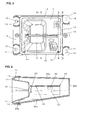
- FIG. 3 is a front elevation view of the card reader 1 relating to the embodiment of the present invention.
- FIG. 4 is a cross sectional view of the card reader 1 shown in FIG. 3 , taken along the line A-A in the figure.
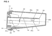
- FIG. 5 is a cross sectional view of the card reader 1 shown in FIG. 3 , taken along the line B-B in the figure.
- the card path 21 described above continuously extends from the card inlet slot 12. Furthermore, placed at an inner side of the card path 21 so as to face the card path 21 is a card processing section 25 that reads and writes information data from/to a card.
- the card processing section 25 includes, for example, a magnetic head 60 and an IC contact 50.
- the card path 21 is so placed as to have a card inserted horizontally from the card inlet slot 12 when the card reader 1 is installed horizontally.
- a control circuit board 24 for controlling the card reader 1 is positioned over the card path 21 that is placed as described above.
- the card reader 1 is sealed with the case body 20, and there is a hollow section between a lower side of the card path 21 and the case body 20. Accordingly, there is a chance that water infiltrated into the card path 21 passes through the hollow section to drop to the bottom wall 20c of the case body 20.
- a shutter 22 placed between the card inlet slot 12 and the card path 21 is a shutter 22 that opens and closes the card path 21.
- the shutter 22 is so pressed in a direction as to close the card path 21 by a shutter returning spring.
- the shutter 22 gets opened by the card.
- the shutter 22 gets closed by the shutter returning spring at the time when the card gets out of the shutter 22.
- a full-range shutter that covers a full extent of the card path 21 is used as the shutter.
- a rib 20d is formed at an edge (a front end) of the bottom wall 20c of the case body 20, and the rib 20d prevents any water leakage at a connection part between the bottom wall 20c and the front bezel 10.
- the rib 20d is extended from the case body 20 for overlapping so that the infiltrated water is guided to the liquid drain holes 30 more surely and this arrangement also prevents any water infiltration from the connection part due to backwater.
- a sealing member 40 (a packing) made of sponge, rubber, or any equivalent is placed at a lower part of the connection part between the bottom wall 20c and the front bezel 10 to prevent any water infiltration through the connection part more surely.
- a metallic plate 23 is installed at a root side of the rib 20d in a direction perpendicular to the card insertion direction.
- the metallic plate 23 is as an example of a breaking-in protection member working for preventing any foreign material breaking in through the liquid drain holes 30.
- the metallic plate 23 made of metal is used in this embodiment as the member for preventing any foreign material, but the material of the metallic plate 23 is not limited to metal and any other material can be used.
- the bottom wall 20c of the case body 20 is tilted. Therefore, water infiltrated into the case body 20 can be drained externally through the liquid drain holes 30 (Since no drain tube is used, this arrangement enables a manufacturing process to be simplified and production costs to be reduced).
- the card reader 1 when the card reader 1 is installed into the higher-level device, it is not required to tilt an entire part of the card reader 1 (a unit) in an obliquely frontward direction. Therefore, this arrangement can prevent card operation performance from worsening, such as card insertion into the card inlet slot 12 becoming difficult.
- the card processing section 25 placed so as to face the card path 21 is unlikely to get drenched while the shutter 22 is closed.
- most of water infiltrated through the card inlet slot 12 is blocked at the shutter 22 and the blocked water drops to the bottom wall 20c of the case body 20.
- the dropped water flows along the bottom wall 20c to the front bezel 10, and eventually drains off externally through the liquid drain holes 30.
- the metallic plate 23 Since the metallic plate 23 is installed at the root side of the rib 20d, the metallic plate 23 can prevent a stick from reaching the bottom wall 20c even if the stick is poked through the liquid drain holes 30, so that this arrangement can prevent damages of internals of the card processing apparatus.
- size of the liquid drain holes 30 is set to be greater than size of all gaps which may cause water infiltration, including a gap between the front bezel 10 and a main body of the card reader 1, and so on. Therefore, water infiltrated into the case body 20 can effectively be drained externally through the liquid drain holes 30.
- the card processing apparatus relating to the present invention is useful for enabling prevention of water accumulation inside a case, even if the card processing apparatus is equipped with the case, while avoiding deterioration of convenience performance.
Abstract
Description
- The present invention relates to a card processing apparatus that takes in a card such as a magnetic card, and then reads and writes information data from/to the card.
- Magnetic cards and IC cards are generally used, for example at banking facilities and automatic vending machines, as cards for implementation of personal verification and cashless service. A magnetic card includes magnetic stripes formed on a surface of a plastic substrate, and an IC card includes an IC chip embedded in a plastic substrate. Reading and writing information data from/to these cards is carried out by a card processing apparatus (a card reader) equipped with a magnetic head and/or an IC contact. The card processing apparatus is usually mounted, for example, on a higher-level device (or a panel of the higher-level device) such as an automatic vending machine.
- Thus, according to requirements for a security-compatible card reader (in compliance with PCI-PED standards), an entire part of the card reader needs to be covered with a tamper-resistant case for the purpose of prevention of any tampering access. Also, from a viewpoint of environment-resistance such as dust-proof and waterproof, it is needed to cover the card reader with such a tamper-resistant case. For example, in the case of a card reader disclosed by
Patent Document 1, a tamper-resistant case is placed in order to cover various elements including a circuit board (an electronic circuit plate 7 in Patent Document 1). - Specification of United States Patent No.
US5698832 - In a case where the card reader is used in an outdoor environment (for example, being mounted at an automatic vending machine), it is required to prevent the card reader devices from any failure resulted from somewhat of rainwater infiltrated through a card inlet slot. However, the card reader equipped with the case described above (tamper-resistant case) may not enable prevention of the problem of such failure. Furthermore, even when it is possible to prevent the card reader devices from any such failure, the card reader may impair convenience performance.
- For example, a cover member (a hood, etc.) may be placed around the card inlet slot to prevent any rainwater infiltration. However, for such an arrangement, the cover member itself is additionally required so as to cause an increase of production cost. Furthermore, when a card is handled, the cover member needs to be opened and closed so as to worsen operation performance and impair convenience performance. Moreover, despite the cover member being used; if once rainwater has infiltrated through the card inlet slot, the rainwater gets accumulated inside the case and the accumulated rainwater may cause malfunction of the card reader devices.
- It is an object of the present invention to provide a card processing apparatus that, even being a card processing apparatus equipped with a case, can avoid deterioration of convenience performance and prevent any water accumulation inside the case and consequently decrease a failure rate.
- To solve the problem identified above, the present invention provides the following aspects.
-
- (1) A card processing apparatus including: a front bezel, a card inlet slot placed in the front bezel, a card path continuously extending from the card inlet slot, a shutter installed between the card inlet slot and the card path for opening and closing the card path, a case body closely contacting the front bezel and internally including the card path, a tilted part that is tilted so as to become further away gradually from the card path in a direction from an inner part of the case body toward the front bezel to guide a liquid infiltrated through the card inlet slot, and liquid drain holes positioned at the front side of the front bezel to go through continuously to a side of the case body for draining the liquid.
- According to the present invention, the card processing apparatus includes: the front bezel, the card inlet slot, the shutter installed between the card inlet slot and the card path, the case body internally including the card path, the tilted part that is tilted so as to become further away gradually from the card path in the direction from the inner part of the case body toward the front bezel to guide the liquid infiltrated through the card inlet slot, and the liquid drain holes positioned at the front side of the front bezel to go through continuously to the side of the case body for draining the liquid. Therefore, the card processing apparatus enables decrease in a failure rate while avoiding deterioration of convenience performance.
- In other words; even if water comes into the case, for example, through the card inlet slot, the water can be drained through the tilted part and the liquid drain holes. Therefore, this arrangement enables decrease in a rate of failure due to water accumulation inside the case. Furthermore, since rainwater and so on infiltrated into the case can be drained afterward, it is not needed to install any cover member that requires opening and closing operations. Therefore, this arrangement enables prevention of deterioration of convenience performance, such as worsening card operation performance.
- Moreover, since the tilted part is tilted so as to become further away gradually from the card path in the direction from the inner part of the case body toward the front bezel, it is not needed to tilt an entire part of the card processing apparatus in an obliquely front-downward direction (Tilting the card processing apparatus in an obliquely front-downward direction brings difficulty for inserting the card into the card inlet slot and worsens card operation performance). Therefore, this arrangement enables prevention of deterioration of convenience performance, such as worsening card operation performance.
-
- (2) The card processing apparatus further including a card processing section located at an inner side of the card path for reading and writing information data recorded in the card.
- According to the present invention, the card processing apparatus includes the card processing section (such as an IC contact) located at the inner side of the card path for reading and writing information data recorded in the card. Therefore, malfunction of the card reader devices can effectively be avoided.
- Namely, structural elements according to the present invention include not only the tilted part and the liquid drain holes but also the shutter placed between the card inlet slot and the card path. Therefore, even though rainwater and so on get infiltrated into the case, the rainwater and so on are unlikely to reach an inner side of the card path as far as the shutter is closed. Thus, by locating the card processing section at the card path, it becomes possible more surely to prevent malfunction of the card reader devices (for example, failure due to short-circuiting of the lC contact protruded to the card path).
-
- (3) The card processing apparatus, wherein the card path is so placed as to have the card inserted in a horizontal direction from the card inlet slot, and a control circuit board for controlling the card processing apparatus is located at a position higher than the card path.
- According to the present invention, the card path is so placed as to have the card inserted in the horizontal direction from the card inlet slot, and the control circuit board for controlling the card processing apparatus is located at the position higher than the card path. Therefore, even if water passes through the shutter to get infiltrated into the card path (for example, a drenched card is inserted), the water drops to the tilted part. Then, the control circuit board is unlikely to get drenched, and it becomes possible more surely to prevent malfunction of the card reader devices.
-
- (4) The card processing apparatus, wherein a breaking-in protection member working for preventing any foreign material breaking in through the liquid drain holes is placed at the card processing apparatus' inner side of the liquid drain holes.
- According to the present invention, the breaking-in protection member (for example, a metallic plate) working for preventing any foreign material breaking in through the liquid drain holes is placed at the card processing apparatus' inner side of the liquid drain holes. Therefore, even if a stick is recklessly poked into the liquid drain holes, this arrangement can prevent damages of internals of the card processing apparatus (for example, internals of the tilted part).
- Equipped with a case, a card processing apparatus relating to the present invention makes it possible to prevent any water being accumulated in the case and to keep devices of the card processing apparatus from failure while convenience performance of the devices being taken into consideration.
- A preferred embodiment of the present invention is described below with reference to the accompanying drawings.
-
FIG. 1 is a perspective view showing an external structural view of acard reader 1 relating to an embodiment of the present invention.FIG. 2 is a side view of thecard reader 1 shown inFIG. 1 . Though thecard reader 1 shown inFIG. 1 is applied as a card processing apparatus in the present embodiment, the present invention can also be applied to other kinds of card readers. - In
FIG. 1 and FIG. 2 , thecard reader 1 includes afront bezel 10 having afront face 11 and acard inlet slot 12, both of which expose themselves from an opening of a panel of a higher-level device; a card path 21 (Refer toFIG. 4 to be explained later) extending from thecard inlet slot 12; and acase body 20 closely contacting thefront bezel 10 and having thecard path 21 internally. Thecase body 20 is assembled to thefront bezel 10 withscrews 17. - Formed in the
front bezel 10 are acircumferential contacting surface 13 that contacts the panel of the higher-level device (not illustrated), and fixingsurfaces 14 that contact protrusions located at a rear side (a side toward the higher-level device) of the panel. 4fixing surfaces 14 are formed at 4 corners of thefront bezel 10, and accordingly there are also 4 protrusions located at the rear side of the panel of the higher-level device. Thefront face 11, thecircumferential contacting surface 13, and thefixing surfaces 14 are formed in a step structure in a direction toward an inside of the higher-level device. As a result, only thefront face 11 can be seen externally through the panel. - As shown in
FIG. 2 , thecase body 20 includes atop wall 20a, aside wall 20b, and abottom wall 20c. When thecard reader 1 is installed into the upper-level device so as to have a card inserted in a horizontal direction, thebottom wall 20c is tilted for about 10 degrees. Namely, in a direction from an inner part of thecase body 20 toward thefront bezel 10, thebottom wall 20c is tilted so as to become further away gradually from thecard path 21. This arrangement leads a liquid infiltrated through the card inlet slot to thefront bezel 10. Thus, in the present embodiment, thebottom wall 20c works as "a tilted part". Incidentally, thecard reader 1 is fixed with screws to the panel of the higher-level device by using mountingholes 18. - The
card reader 1 relating to the present embodiment is equipped with liquid drain holes 30 that are located at (a lower section of) a front surface of thefront bezel 10 and go through to a side of thecase body 20 for draining the liquid. Since these drain holes are placed, any rainwater and so on can be drained afterward even if such a liquid once infiltrates throughcard inlet slot 12 into thecase body 20. Described below in detail with reference toFIG. 3 through FIG. 5 is a way of draining the liquid through the liquid drain holes 30. -
FIG. 3 is a front elevation view of thecard reader 1 relating to the embodiment of the present invention.FIG. 4 is a cross sectional view of thecard reader 1 shown inFIG. 3 , taken along the line A-A in the figure.FIG. 5 is a cross sectional view of thecard reader 1 shown inFIG. 3 , taken along the line B-B in the figure. - As
FIG. 4 shows, thecard path 21 described above continuously extends from thecard inlet slot 12. Furthermore, placed at an inner side of thecard path 21 so as to face thecard path 21 is acard processing section 25 that reads and writes information data from/to a card. Thecard processing section 25 includes, for example, amagnetic head 60 and anIC contact 50. Thecard path 21 is so placed as to have a card inserted horizontally from thecard inlet slot 12 when thecard reader 1 is installed horizontally. Then, acontrol circuit board 24 for controlling thecard reader 1 is positioned over thecard path 21 that is placed as described above. In the present embodiment, thecard reader 1 is sealed with thecase body 20, and there is a hollow section between a lower side of thecard path 21 and thecase body 20. Accordingly, there is a chance that water infiltrated into thecard path 21 passes through the hollow section to drop to thebottom wall 20c of thecase body 20. - Furthermore, placed between the
card inlet slot 12 and thecard path 21 is ashutter 22 that opens and closes thecard path 21. Theshutter 22 is so pressed in a direction as to close thecard path 21 by a shutter returning spring. When a card inserted through thecard inlet slot 12 arrives at theshutter 22, theshutter 22 gets opened by the card. Meanwhile, if once the inserted card is pulled out, theshutter 22 gets closed by the shutter returning spring at the time when the card gets out of theshutter 22. In the present embodiment, a full-range shutter that covers a full extent of thecard path 21 is used as the shutter. - As shown in
FIG. 4 andFIG. 5 , arib 20d is formed at an edge (a front end) of thebottom wall 20c of thecase body 20, and therib 20d prevents any water leakage at a connection part between thebottom wall 20c and thefront bezel 10. In other words, at the connection part between thefront bezel 10 and thebottom wall 20c, therib 20d is extended from thecase body 20 for overlapping so that the infiltrated water is guided to the liquid drain holes 30 more surely and this arrangement also prevents any water infiltration from the connection part due to backwater. Furthermore, in thecard reader 1 relating to the present embodiment, as shown inFIG. 5 , a sealing member 40 (a packing) made of sponge, rubber, or any equivalent is placed at a lower part of the connection part between thebottom wall 20c and thefront bezel 10 to prevent any water infiltration through the connection part more surely. - At the card processing apparatus' inner side of the liquid drain holes 30, a
metallic plate 23 is installed at a root side of therib 20d in a direction perpendicular to the card insertion direction. Themetallic plate 23 is as an example of a breaking-in protection member working for preventing any foreign material breaking in through the liquid drain holes 30. Incidentally, themetallic plate 23 made of metal is used in this embodiment as the member for preventing any foreign material, but the material of themetallic plate 23 is not limited to metal and any other material can be used. - As described above, according to the
card reader 1 described above including thecase body 20, thebottom wall 20c of thecase body 20 is tilted. Therefore, water infiltrated into thecase body 20 can be drained externally through the liquid drain holes 30 (Since no drain tube is used, this arrangement enables a manufacturing process to be simplified and production costs to be reduced). - Furthermore, when the
card reader 1 is installed into the higher-level device, it is not required to tilt an entire part of the card reader 1 (a unit) in an obliquely frontward direction. Therefore, this arrangement can prevent card operation performance from worsening, such as card insertion into thecard inlet slot 12 becoming difficult. - Moreover, since the
card reader 1 is equipped with theshutter 22 to open and close thecard path 21, thecard processing section 25 placed so as to face thecard path 21 is unlikely to get drenched while theshutter 22 is closed. In other words, most of water infiltrated through thecard inlet slot 12 is blocked at theshutter 22 and the blocked water drops to thebottom wall 20c of thecase body 20. Then, the dropped water flows along thebottom wall 20c to thefront bezel 10, and eventually drains off externally through the liquid drain holes 30. Thus, this arrangement prevents malfunction of the card reader devices including thelC contact 50 more surely. - Still further, even in a case where water have passed through the
shutter 22 to infiltrate into thecard path 21, thecontrol circuit board 24 is unlikely to get drenched since thecontrol circuit board 24 for controlling thecard reader 1 is located at a position higher than thecard path 21 as shown inFIG. 4 andFIG. 5 . Thus, this arrangement prevents malfunction of the card reader devices more surely. - Since the
metallic plate 23 is installed at the root side of therib 20d, themetallic plate 23 can prevent a stick from reaching thebottom wall 20c even if the stick is poked through the liquid drain holes 30, so that this arrangement can prevent damages of internals of the card processing apparatus. - Furthermore, in the present embodiment, size of the liquid drain holes 30 is set to be greater than size of all gaps which may cause water infiltration, including a gap between the
front bezel 10 and a main body of thecard reader 1, and so on. Therefore, water infiltrated into thecase body 20 can effectively be drained externally through the liquid drain holes 30. - The card processing apparatus relating to the present invention is useful for enabling prevention of water accumulation inside a case, even if the card processing apparatus is equipped with the case, while avoiding deterioration of convenience performance.
-
-
FIG. 1 is a perspective view showing an external structural view of a card reader relating to an embodiment of the present invention. -
FIG. 2 is a side view of the card reader shown inFIG. 1 . -
FIG. 3 is a front elevation view of the card reader relating to the embodiment of the present invention. -
FIG. 4 is a cross sectional view of the card reader shown inFIG. 3 , taken along the line A-A in the figure. -
FIG. 5 is a cross sectional view of the card reader shown inFIG. 3 , taken along the line B-B in the figure. -
- 1. Card reader
- 10. Bezel
- 11. Front face
- 12. Card inlet slot
- 13. Circumferential contacting surface
- 14. Fixing surface
- 17. Screw
- 18. Mounting hole
- 20. Case body
- 21. Card path
- 22. Shutter
- 23. Metallic plate
- 24. Control circuit board
- 25. Card processing section
- 30. Liquid drain hole
- 40. Sealing member
- 50. IC contact
- 60. Magnetic head
- 70. Display LED
Claims (4)
- A card processing apparatus comprising:a front bezel,a card inlet slot placed in the front bezel,a card path continuously extending from the card inlet slot,a shutter installed between the card inlet slot and the card path for opening and closing the card path,a case body closely contacting the front bezel and internally including the card path,a tilted part that is tilted so as to become further away gradually from the card path in a direction from an inner part of the case body toward the front bezel to guide a liquid infiltrated through the card inlet slot, andliquid drain holes positioned at the front side of the front bezel to go through continuously to a side of the case body for draining the liquid.
- The card processing apparatus according to Claim 1:further comprising, a card processing section located at an inner side of the card path for reading and writing information data recorded in a card.
- The card processing apparatus according to Claim 1 or Claim 2:wherein the card path is so placed as to have the card inserted in a horizontal direction from the card inlet slot, anda control circuit board for controlling the card processing apparatus is located at a position higher than the card path.
- The card processing apparatus according to at least one of Claim 1 through Claim 3:wherein a breaking-in protection member working for preventing any foreign material breaking in through the liquid drain holes is placed at the card processing apparatus' inner side of the liquid drain holes.
Applications Claiming Priority (1)
| Application Number | Priority Date | Filing Date | Title |
|---|---|---|---|
| JP2007016924A JP5088931B2 (en) | 2007-01-26 | 2007-01-26 | Card processing device |
Publications (3)
| Publication Number | Publication Date |
|---|---|
| EP1950693A2 true EP1950693A2 (en) | 2008-07-30 |
| EP1950693A3 EP1950693A3 (en) | 2011-06-01 |
| EP1950693B1 EP1950693B1 (en) | 2012-08-22 |
Family
ID=39367717
Family Applications (1)
| Application Number | Title | Priority Date | Filing Date |
|---|---|---|---|
| EP08001008A Not-in-force EP1950693B1 (en) | 2007-01-26 | 2008-01-21 | Card processing apparatus |
Country Status (3)
| Country | Link |
|---|---|
| US (1) | US8251293B2 (en) |
| EP (1) | EP1950693B1 (en) |
| JP (1) | JP5088931B2 (en) |
Cited By (3)
| Publication number | Priority date | Publication date | Assignee | Title |
|---|---|---|---|---|
| CN102473242A (en) * | 2009-08-07 | 2012-05-23 | 日本电产三协株式会社 | Card reader |
| CN102982609A (en) * | 2011-05-25 | 2013-03-20 | 日立欧姆龙金融系统有限公司 | Card handling device |
| CN105590366A (en) * | 2014-11-14 | 2016-05-18 | 日立金融设备系统(深圳)有限公司 | Automatic trading device and false card detection method for same |
Families Citing this family (43)
| Publication number | Priority date | Publication date | Assignee | Title |
|---|---|---|---|---|
| US6676127B2 (en) | 1997-03-13 | 2004-01-13 | Shuffle Master, Inc. | Collating and sorting apparatus |
| US6655684B2 (en) | 1998-04-15 | 2003-12-02 | Shuffle Master, Inc. | Device and method for forming and delivering hands from randomly arranged decks of playing cards |
| US6254096B1 (en) | 1998-04-15 | 2001-07-03 | Shuffle Master, Inc. | Device and method for continuously shuffling cards |
| US8590896B2 (en) | 2000-04-12 | 2013-11-26 | Shuffle Master Gmbh & Co Kg | Card-handling devices and systems |
| US7677565B2 (en) | 2001-09-28 | 2010-03-16 | Shuffle Master, Inc | Card shuffler with card rank and value reading capability |
| US8616552B2 (en) | 2001-09-28 | 2013-12-31 | Shfl Entertainment, Inc. | Methods and apparatuses for an automatic card handling device and communication networks including same |
| US8337296B2 (en) | 2001-09-28 | 2012-12-25 | SHFL entertaiment, Inc. | Method and apparatus for using upstream communication in a card shuffler |
| US7753373B2 (en) | 2001-09-28 | 2010-07-13 | Shuffle Master, Inc. | Multiple mode card shuffler and card reading device |
| US8011661B2 (en) | 2001-09-28 | 2011-09-06 | Shuffle Master, Inc. | Shuffler with shuffling completion indicator |
| US6886829B2 (en) | 2002-02-08 | 2005-05-03 | Vendingdata Corporation | Image capturing card shuffler |
| US20060066048A1 (en) | 2004-09-14 | 2006-03-30 | Shuffle Master, Inc. | Magnetic jam detection in a card shuffler |
| US7764836B2 (en) | 2005-06-13 | 2010-07-27 | Shuffle Master, Inc. | Card shuffler with card rank and value reading capability using CMOS sensor |
| US7556266B2 (en) | 2006-03-24 | 2009-07-07 | Shuffle Master Gmbh & Co Kg | Card shuffler with gravity feed system for playing cards |
| US8353513B2 (en) | 2006-05-31 | 2013-01-15 | Shfl Entertainment, Inc. | Card weight for gravity feed input for playing card shuffler |
| US8342525B2 (en) | 2006-07-05 | 2013-01-01 | Shfl Entertainment, Inc. | Card shuffler with adjacent card infeed and card output compartments |
| US8579289B2 (en) | 2006-05-31 | 2013-11-12 | Shfl Entertainment, Inc. | Automatic system and methods for accurate card handling |
| US8070574B2 (en) | 2007-06-06 | 2011-12-06 | Shuffle Master, Inc. | Apparatus, system, method, and computer-readable medium for casino card handling with multiple hand recall feature |
| US8919775B2 (en) | 2006-11-10 | 2014-12-30 | Bally Gaming, Inc. | System for billing usage of an automatic card handling device |
| US8967621B2 (en) | 2009-04-07 | 2015-03-03 | Bally Gaming, Inc. | Card shuffling apparatuses and related methods |
| US7988152B2 (en) | 2009-04-07 | 2011-08-02 | Shuffle Master, Inc. | Playing card shuffler |
| US8800993B2 (en) | 2010-10-14 | 2014-08-12 | Shuffle Master Gmbh & Co Kg | Card handling systems, devices for use in card handling systems and related methods |
| US8485527B2 (en) | 2011-07-29 | 2013-07-16 | Savant Shuffler LLC | Card shuffler |
| US9731190B2 (en) | 2011-07-29 | 2017-08-15 | Bally Gaming, Inc. | Method and apparatus for shuffling and handling cards |
| US8960674B2 (en) | 2012-07-27 | 2015-02-24 | Bally Gaming, Inc. | Batch card shuffling apparatuses including multi-card storage compartments, and related methods |
| US9378766B2 (en) | 2012-09-28 | 2016-06-28 | Bally Gaming, Inc. | Card recognition system, card handling device, and method for tuning a card handling device |
| US9511274B2 (en) | 2012-09-28 | 2016-12-06 | Bally Gaming Inc. | Methods for automatically generating a card deck library and master images for a deck of cards, and a related card processing apparatus |
| JP6078457B2 (en) * | 2013-11-08 | 2017-02-08 | 日本電産サンキョー株式会社 | Card reader |
| SG11201608344WA (en) | 2014-04-11 | 2016-11-29 | Bally Gaming Inc | Method and apparatus for shuffling and handling cards |
| US9474957B2 (en) | 2014-05-15 | 2016-10-25 | Bally Gaming, Inc. | Playing card handling devices, systems, and methods for verifying sets of cards |
| USD764599S1 (en) | 2014-08-01 | 2016-08-23 | Bally Gaming, Inc. | Card shuffler device |
| US9566501B2 (en) | 2014-08-01 | 2017-02-14 | Bally Gaming, Inc. | Hand-forming card shuffling apparatuses including multi-card storage compartments, and related methods |
| US9504905B2 (en) | 2014-09-19 | 2016-11-29 | Bally Gaming, Inc. | Card shuffling device and calibration method |
| JP6357406B2 (en) * | 2014-10-30 | 2018-07-11 | 日本電産サンキョー株式会社 | Card reader |
| US9993719B2 (en) | 2015-12-04 | 2018-06-12 | Shuffle Master Gmbh & Co Kg | Card handling devices and related assemblies and components |
| US10339765B2 (en) | 2016-09-26 | 2019-07-02 | Shuffle Master Gmbh & Co Kg | Devices, systems, and related methods for real-time monitoring and display of related data for casino gaming devices |
| US10933300B2 (en) | 2016-09-26 | 2021-03-02 | Shuffle Master Gmbh & Co Kg | Card handling devices and related assemblies and components |
| JP6897283B2 (en) * | 2017-04-27 | 2021-06-30 | 株式会社デンソー | Vehicle media reader |
| US11896891B2 (en) | 2018-09-14 | 2024-02-13 | Sg Gaming, Inc. | Card-handling devices and related methods, assemblies, and components |
| US11376489B2 (en) | 2018-09-14 | 2022-07-05 | Sg Gaming, Inc. | Card-handling devices and related methods, assemblies, and components |
| US11338194B2 (en) | 2018-09-28 | 2022-05-24 | Sg Gaming, Inc. | Automatic card shufflers and related methods of automatic jam recovery |
| CN112546608A (en) | 2019-09-10 | 2021-03-26 | 夏佛马士特公司 | Card handling apparatus for defect detection and related methods |
| US11173383B2 (en) | 2019-10-07 | 2021-11-16 | Sg Gaming, Inc. | Card-handling devices and related methods, assemblies, and components |
| US11443123B2 (en) * | 2021-01-05 | 2022-09-13 | Elo Touch Solutions, Inc. | Liquid impervious smart card reader |
Citations (1)
| Publication number | Priority date | Publication date | Assignee | Title |
|---|---|---|---|---|
| US5698832A (en) | 1995-03-31 | 1997-12-16 | Neuron Corporation | Magnetic card reading apparatus |
Family Cites Families (9)
| Publication number | Priority date | Publication date | Assignee | Title |
|---|---|---|---|---|
| JPH0227249U (en) | 1988-08-08 | 1990-02-22 | ||
| JP2689705B2 (en) * | 1990-08-03 | 1997-12-10 | 富士電機株式会社 | Card terminal |
| US5892210A (en) * | 1996-10-10 | 1999-04-06 | Coin Acceptors, Inc. | Smart card reader with liquid diverter system |
| US6042010A (en) * | 1997-01-10 | 2000-03-28 | Matsushita Electric Industrial Co., Ltd. | Card reader and a method of installing a card reader |
| JP3376893B2 (en) * | 1997-10-28 | 2003-02-10 | 松下電器産業株式会社 | Card reader |
| JP3959297B2 (en) * | 2002-04-10 | 2007-08-15 | 日立オムロンターミナルソリューションズ株式会社 | Banknote handling equipment |
| US6983879B2 (en) * | 2002-11-26 | 2006-01-10 | Diebold Self-Service Systems Division Of Diebold, Incorporated | Cash dispensing automated banking machine with improved resistance to fraud |
| US7364076B2 (en) * | 2004-10-25 | 2008-04-29 | Nidec Sankyo Corporation | Card reader |
| US7870997B2 (en) * | 2005-07-01 | 2011-01-18 | Diebold Self-Service Systems Division Of Diebold Incorporated | ATM that can center different sized cash stacks in a cash outlet opening |
-
2007
- 2007-01-26 JP JP2007016924A patent/JP5088931B2/en not_active Expired - Fee Related
-
2008
- 2008-01-21 EP EP08001008A patent/EP1950693B1/en not_active Not-in-force
- 2008-01-28 US US12/020,617 patent/US8251293B2/en active Active
Patent Citations (1)
| Publication number | Priority date | Publication date | Assignee | Title |
|---|---|---|---|---|
| US5698832A (en) | 1995-03-31 | 1997-12-16 | Neuron Corporation | Magnetic card reading apparatus |
Cited By (6)
| Publication number | Priority date | Publication date | Assignee | Title |
|---|---|---|---|---|
| CN102473242A (en) * | 2009-08-07 | 2012-05-23 | 日本电产三协株式会社 | Card reader |
| CN102473242B (en) * | 2009-08-07 | 2014-06-25 | 日本电产三协株式会社 | Card reader |
| CN102982609A (en) * | 2011-05-25 | 2013-03-20 | 日立欧姆龙金融系统有限公司 | Card handling device |
| CN102982609B (en) * | 2011-05-25 | 2015-02-11 | 日立欧姆龙金融系统有限公司 | Card handling device |
| CN105590366A (en) * | 2014-11-14 | 2016-05-18 | 日立金融设备系统(深圳)有限公司 | Automatic trading device and false card detection method for same |
| CN105590366B (en) * | 2014-11-14 | 2018-05-15 | 日立金融设备系统(深圳)有限公司 | The false card test method of automatic trading apparatus and automatic trading apparatus |
Also Published As
| Publication number | Publication date |
|---|---|
| EP1950693A3 (en) | 2011-06-01 |
| JP2008186085A (en) | 2008-08-14 |
| EP1950693B1 (en) | 2012-08-22 |
| US8251293B2 (en) | 2012-08-28 |
| US20080185442A1 (en) | 2008-08-07 |
| JP5088931B2 (en) | 2012-12-05 |
Similar Documents
| Publication | Publication Date | Title |
|---|---|---|
| EP1950693B1 (en) | Card processing apparatus | |
| US8302857B2 (en) | Tamper detection mechanism and card processing device | |
| US6042010A (en) | Card reader and a method of installing a card reader | |
| EP0725401A2 (en) | Information storage apparatus and information processing apparatus using the same | |
| JP2000024268A (en) | Game machine | |
| JPH11226219A (en) | Control board box, molding die, injection molding method and control board of game machine | |
| CN100380398C (en) | Card receiving device | |
| US8081445B2 (en) | Drainage structure and information processing unit | |
| JP2689705B2 (en) | Card terminal | |
| EP1808829A1 (en) | Reader/writer unit of automatic vending machine | |
| JP2007323300A (en) | On-vehicle communication terminal equipment and ic card reading device | |
| JP4488442B2 (en) | Game machine | |
| JP2008227289A (en) | Electronic apparatus | |
| JP7343225B1 (en) | card insertion device | |
| JP3376893B2 (en) | Card reader | |
| JP5012364B2 (en) | Card mounting device | |
| JP7267528B2 (en) | Card reader storage case and card reader device using the same | |
| JPH07254054A (en) | Electronic card and connector device where card is inserted | |
| JP2006319854A (en) | Mobile terminal instrument and its shield plate | |
| JP2000137768A (en) | Ic card processor | |
| JP4258943B2 (en) | Connector device | |
| CA3146030A1 (en) | Payment card reading system having a protective flap | |
| JP2002191824A (en) | Control board box | |
| JP3485742B2 (en) | Card handling device | |
| JP4111230B2 (en) | Card reader insertion slot blocking mechanism |
Legal Events
| Date | Code | Title | Description |
|---|---|---|---|
| PUAI | Public reference made under article 153(3) epc to a published international application that has entered the european phase |
Free format text: ORIGINAL CODE: 0009012 |
|
| AK | Designated contracting states |
Kind code of ref document: A2 Designated state(s): AT BE BG CH CY CZ DE DK EE ES FI FR GB GR HR HU IE IS IT LI LT LU LV MC MT NL NO PL PT RO SE SI SK TR |
|
| AX | Request for extension of the european patent |
Extension state: AL BA MK RS |
|
| PUAL | Search report despatched |
Free format text: ORIGINAL CODE: 0009013 |
|
| AK | Designated contracting states |
Kind code of ref document: A3 Designated state(s): AT BE BG CH CY CZ DE DK EE ES FI FR GB GR HR HU IE IS IT LI LT LU LV MC MT NL NO PL PT RO SE SI SK TR |
|
| AX | Request for extension of the european patent |
Extension state: AL BA MK RS |
|
| RIC1 | Information provided on ipc code assigned before grant |
Ipc: G06K 7/00 20060101ALI20110426BHEP Ipc: G06K 13/08 20060101AFI20080520BHEP |
|
| 17P | Request for examination filed |
Effective date: 20111201 |
|
| AKX | Designation fees paid |
Designated state(s): AT BE BG CH CY CZ DE DK EE ES FI FR GB GR HR HU IE IS IT LI LT LU LV MC MT NL NO PL PT RO SE SI SK TR |
|
| GRAP | Despatch of communication of intention to grant a patent |
Free format text: ORIGINAL CODE: EPIDOSNIGR1 |
|
| GRAS | Grant fee paid |
Free format text: ORIGINAL CODE: EPIDOSNIGR3 |
|
| GRAA | (expected) grant |
Free format text: ORIGINAL CODE: 0009210 |
|
| AK | Designated contracting states |
Kind code of ref document: B1 Designated state(s): AT BE BG CH CY CZ DE DK EE ES FI FR GB GR HR HU IE IS IT LI LT LU LV MC MT NL NO PL PT RO SE SI SK TR |
|
| REG | Reference to a national code |
Ref country code: GB Ref legal event code: FG4D |
|
| REG | Reference to a national code |
Ref country code: CH Ref legal event code: EP |
|
| REG | Reference to a national code |
Ref country code: IE Ref legal event code: FG4D |
|
| REG | Reference to a national code |
Ref country code: AT Ref legal event code: REF Ref document number: 572303 Country of ref document: AT Kind code of ref document: T Effective date: 20120915 |
|
| REG | Reference to a national code |
Ref country code: DE Ref legal event code: R096 Ref document number: 602008018144 Country of ref document: DE Effective date: 20121018 |
|
| REG | Reference to a national code |
Ref country code: NL Ref legal event code: VDEP Effective date: 20120822 |
|
| REG | Reference to a national code |
Ref country code: AT Ref legal event code: MK05 Ref document number: 572303 Country of ref document: AT Kind code of ref document: T Effective date: 20120822 |
|
| REG | Reference to a national code |
Ref country code: LT Ref legal event code: MG4D Effective date: 20120822 |
|
| PG25 | Lapsed in a contracting state [announced via postgrant information from national office to epo] |
Ref country code: FI Free format text: LAPSE BECAUSE OF FAILURE TO SUBMIT A TRANSLATION OF THE DESCRIPTION OR TO PAY THE FEE WITHIN THE PRESCRIBED TIME-LIMIT Effective date: 20120822 Ref country code: AT Free format text: LAPSE BECAUSE OF FAILURE TO SUBMIT A TRANSLATION OF THE DESCRIPTION OR TO PAY THE FEE WITHIN THE PRESCRIBED TIME-LIMIT Effective date: 20120822 Ref country code: CY Free format text: LAPSE BECAUSE OF FAILURE TO SUBMIT A TRANSLATION OF THE DESCRIPTION OR TO PAY THE FEE WITHIN THE PRESCRIBED TIME-LIMIT Effective date: 20120822 Ref country code: LT Free format text: LAPSE BECAUSE OF FAILURE TO SUBMIT A TRANSLATION OF THE DESCRIPTION OR TO PAY THE FEE WITHIN THE PRESCRIBED TIME-LIMIT Effective date: 20120822 Ref country code: IS Free format text: LAPSE BECAUSE OF FAILURE TO SUBMIT A TRANSLATION OF THE DESCRIPTION OR TO PAY THE FEE WITHIN THE PRESCRIBED TIME-LIMIT Effective date: 20121222 Ref country code: NO Free format text: LAPSE BECAUSE OF FAILURE TO SUBMIT A TRANSLATION OF THE DESCRIPTION OR TO PAY THE FEE WITHIN THE PRESCRIBED TIME-LIMIT Effective date: 20121122 Ref country code: HR Free format text: LAPSE BECAUSE OF FAILURE TO SUBMIT A TRANSLATION OF THE DESCRIPTION OR TO PAY THE FEE WITHIN THE PRESCRIBED TIME-LIMIT Effective date: 20120822 |
|
| PG25 | Lapsed in a contracting state [announced via postgrant information from national office to epo] |
Ref country code: BE Free format text: LAPSE BECAUSE OF FAILURE TO SUBMIT A TRANSLATION OF THE DESCRIPTION OR TO PAY THE FEE WITHIN THE PRESCRIBED TIME-LIMIT Effective date: 20120822 Ref country code: SI Free format text: LAPSE BECAUSE OF FAILURE TO SUBMIT A TRANSLATION OF THE DESCRIPTION OR TO PAY THE FEE WITHIN THE PRESCRIBED TIME-LIMIT Effective date: 20120822 Ref country code: GR Free format text: LAPSE BECAUSE OF FAILURE TO SUBMIT A TRANSLATION OF THE DESCRIPTION OR TO PAY THE FEE WITHIN THE PRESCRIBED TIME-LIMIT Effective date: 20121123 Ref country code: PT Free format text: LAPSE BECAUSE OF FAILURE TO SUBMIT A TRANSLATION OF THE DESCRIPTION OR TO PAY THE FEE WITHIN THE PRESCRIBED TIME-LIMIT Effective date: 20121224 Ref country code: SE Free format text: LAPSE BECAUSE OF FAILURE TO SUBMIT A TRANSLATION OF THE DESCRIPTION OR TO PAY THE FEE WITHIN THE PRESCRIBED TIME-LIMIT Effective date: 20120822 Ref country code: LV Free format text: LAPSE BECAUSE OF FAILURE TO SUBMIT A TRANSLATION OF THE DESCRIPTION OR TO PAY THE FEE WITHIN THE PRESCRIBED TIME-LIMIT Effective date: 20120822 |
|
| PG25 | Lapsed in a contracting state [announced via postgrant information from national office to epo] |
Ref country code: NL Free format text: LAPSE BECAUSE OF FAILURE TO SUBMIT A TRANSLATION OF THE DESCRIPTION OR TO PAY THE FEE WITHIN THE PRESCRIBED TIME-LIMIT Effective date: 20120822 |
|
| PG25 | Lapsed in a contracting state [announced via postgrant information from national office to epo] |
Ref country code: DK Free format text: LAPSE BECAUSE OF FAILURE TO SUBMIT A TRANSLATION OF THE DESCRIPTION OR TO PAY THE FEE WITHIN THE PRESCRIBED TIME-LIMIT Effective date: 20120822 Ref country code: RO Free format text: LAPSE BECAUSE OF FAILURE TO SUBMIT A TRANSLATION OF THE DESCRIPTION OR TO PAY THE FEE WITHIN THE PRESCRIBED TIME-LIMIT Effective date: 20120822 Ref country code: ES Free format text: LAPSE BECAUSE OF FAILURE TO SUBMIT A TRANSLATION OF THE DESCRIPTION OR TO PAY THE FEE WITHIN THE PRESCRIBED TIME-LIMIT Effective date: 20121203 Ref country code: CZ Free format text: LAPSE BECAUSE OF FAILURE TO SUBMIT A TRANSLATION OF THE DESCRIPTION OR TO PAY THE FEE WITHIN THE PRESCRIBED TIME-LIMIT Effective date: 20120822 Ref country code: EE Free format text: LAPSE BECAUSE OF FAILURE TO SUBMIT A TRANSLATION OF THE DESCRIPTION OR TO PAY THE FEE WITHIN THE PRESCRIBED TIME-LIMIT Effective date: 20120822 |
|
| PG25 | Lapsed in a contracting state [announced via postgrant information from national office to epo] |
Ref country code: SK Free format text: LAPSE BECAUSE OF FAILURE TO SUBMIT A TRANSLATION OF THE DESCRIPTION OR TO PAY THE FEE WITHIN THE PRESCRIBED TIME-LIMIT Effective date: 20120822 Ref country code: PL Free format text: LAPSE BECAUSE OF FAILURE TO SUBMIT A TRANSLATION OF THE DESCRIPTION OR TO PAY THE FEE WITHIN THE PRESCRIBED TIME-LIMIT Effective date: 20120822 Ref country code: IT Free format text: LAPSE BECAUSE OF FAILURE TO SUBMIT A TRANSLATION OF THE DESCRIPTION OR TO PAY THE FEE WITHIN THE PRESCRIBED TIME-LIMIT Effective date: 20120822 |
|
| PLBE | No opposition filed within time limit |
Free format text: ORIGINAL CODE: 0009261 |
|
| STAA | Information on the status of an ep patent application or granted ep patent |
Free format text: STATUS: NO OPPOSITION FILED WITHIN TIME LIMIT |
|
| 26N | No opposition filed |
Effective date: 20130523 |
|
| PG25 | Lapsed in a contracting state [announced via postgrant information from national office to epo] |
Ref country code: BG Free format text: LAPSE BECAUSE OF FAILURE TO SUBMIT A TRANSLATION OF THE DESCRIPTION OR TO PAY THE FEE WITHIN THE PRESCRIBED TIME-LIMIT Effective date: 20121122 |
|
| PG25 | Lapsed in a contracting state [announced via postgrant information from national office to epo] |
Ref country code: MC Free format text: LAPSE BECAUSE OF NON-PAYMENT OF DUE FEES Effective date: 20130131 |
|
| REG | Reference to a national code |
Ref country code: CH Ref legal event code: PL |
|
| REG | Reference to a national code |
Ref country code: DE Ref legal event code: R097 Ref document number: 602008018144 Country of ref document: DE Effective date: 20130523 |
|
| REG | Reference to a national code |
Ref country code: IE Ref legal event code: MM4A |
|
| PG25 | Lapsed in a contracting state [announced via postgrant information from national office to epo] |
Ref country code: CH Free format text: LAPSE BECAUSE OF NON-PAYMENT OF DUE FEES Effective date: 20130131 Ref country code: LI Free format text: LAPSE BECAUSE OF NON-PAYMENT OF DUE FEES Effective date: 20130131 |
|
| PG25 | Lapsed in a contracting state [announced via postgrant information from national office to epo] |
Ref country code: IE Free format text: LAPSE BECAUSE OF NON-PAYMENT OF DUE FEES Effective date: 20130121 |
|
| PG25 | Lapsed in a contracting state [announced via postgrant information from national office to epo] |
Ref country code: MT Free format text: LAPSE BECAUSE OF FAILURE TO SUBMIT A TRANSLATION OF THE DESCRIPTION OR TO PAY THE FEE WITHIN THE PRESCRIBED TIME-LIMIT Effective date: 20120822 |
|
| PG25 | Lapsed in a contracting state [announced via postgrant information from national office to epo] |
Ref country code: TR Free format text: LAPSE BECAUSE OF FAILURE TO SUBMIT A TRANSLATION OF THE DESCRIPTION OR TO PAY THE FEE WITHIN THE PRESCRIBED TIME-LIMIT Effective date: 20120822 |
|
| PG25 | Lapsed in a contracting state [announced via postgrant information from national office to epo] |
Ref country code: LU Free format text: LAPSE BECAUSE OF NON-PAYMENT OF DUE FEES Effective date: 20130121 Ref country code: HU Free format text: LAPSE BECAUSE OF FAILURE TO SUBMIT A TRANSLATION OF THE DESCRIPTION OR TO PAY THE FEE WITHIN THE PRESCRIBED TIME-LIMIT; INVALID AB INITIO Effective date: 20080121 |
|
| REG | Reference to a national code |
Ref country code: FR Ref legal event code: PLFP Year of fee payment: 9 |
|
| REG | Reference to a national code |
Ref country code: FR Ref legal event code: PLFP Year of fee payment: 10 |
|
| PGFP | Annual fee paid to national office [announced via postgrant information from national office to epo] |
Ref country code: FR Payment date: 20161215 Year of fee payment: 10 |
|
| PGFP | Annual fee paid to national office [announced via postgrant information from national office to epo] |
Ref country code: DE Payment date: 20170117 Year of fee payment: 10 |
|
| PGFP | Annual fee paid to national office [announced via postgrant information from national office to epo] |
Ref country code: GB Payment date: 20170118 Year of fee payment: 10 |
|
| REG | Reference to a national code |
Ref country code: DE Ref legal event code: R119 Ref document number: 602008018144 Country of ref document: DE |
|
| GBPC | Gb: european patent ceased through non-payment of renewal fee |
Effective date: 20180121 |
|
| PG25 | Lapsed in a contracting state [announced via postgrant information from national office to epo] |
Ref country code: DE Free format text: LAPSE BECAUSE OF NON-PAYMENT OF DUE FEES Effective date: 20180801 Ref country code: FR Free format text: LAPSE BECAUSE OF NON-PAYMENT OF DUE FEES Effective date: 20180131 |
|
| REG | Reference to a national code |
Ref country code: FR Ref legal event code: ST Effective date: 20180928 |
|
| PG25 | Lapsed in a contracting state [announced via postgrant information from national office to epo] |
Ref country code: GB Free format text: LAPSE BECAUSE OF NON-PAYMENT OF DUE FEES Effective date: 20180121 |