EP1950634A2 - Process for adapting measurement suite configuration for gas turbine performance diagnostics - Google Patents
Process for adapting measurement suite configuration for gas turbine performance diagnostics Download PDFInfo
- Publication number
- EP1950634A2 EP1950634A2 EP08250185A EP08250185A EP1950634A2 EP 1950634 A2 EP1950634 A2 EP 1950634A2 EP 08250185 A EP08250185 A EP 08250185A EP 08250185 A EP08250185 A EP 08250185A EP 1950634 A2 EP1950634 A2 EP 1950634A2
- Authority
- EP
- European Patent Office
- Prior art keywords
- matrix
- measurement
- performance
- configuration
- parameters
- Prior art date
- Legal status (The legal status is an assumption and is not a legal conclusion. Google has not performed a legal analysis and makes no representation as to the accuracy of the status listed.)
- Granted
Links
Images
Classifications
-
- G—PHYSICS
- G05—CONTROLLING; REGULATING
- G05B—CONTROL OR REGULATING SYSTEMS IN GENERAL; FUNCTIONAL ELEMENTS OF SUCH SYSTEMS; MONITORING OR TESTING ARRANGEMENTS FOR SUCH SYSTEMS OR ELEMENTS
- G05B23/00—Testing or monitoring of control systems or parts thereof
- G05B23/02—Electric testing or monitoring
- G05B23/0205—Electric testing or monitoring by means of a monitoring system capable of detecting and responding to faults
- G05B23/0218—Electric testing or monitoring by means of a monitoring system capable of detecting and responding to faults characterised by the fault detection method dealing with either existing or incipient faults
- G05B23/0243—Electric testing or monitoring by means of a monitoring system capable of detecting and responding to faults characterised by the fault detection method dealing with either existing or incipient faults model based detection method, e.g. first-principles knowledge model
- G05B23/0254—Electric testing or monitoring by means of a monitoring system capable of detecting and responding to faults characterised by the fault detection method dealing with either existing or incipient faults model based detection method, e.g. first-principles knowledge model based on a quantitative model, e.g. mathematical relationships between inputs and outputs; functions: observer, Kalman filter, residual calculation, Neural Networks
-
- G—PHYSICS
- G05—CONTROLLING; REGULATING
- G05B—CONTROL OR REGULATING SYSTEMS IN GENERAL; FUNCTIONAL ELEMENTS OF SUCH SYSTEMS; MONITORING OR TESTING ARRANGEMENTS FOR SUCH SYSTEMS OR ELEMENTS
- G05B23/00—Testing or monitoring of control systems or parts thereof
- G05B23/02—Electric testing or monitoring
- G05B23/0205—Electric testing or monitoring by means of a monitoring system capable of detecting and responding to faults
- G05B23/0259—Electric testing or monitoring by means of a monitoring system capable of detecting and responding to faults characterized by the response to fault detection
- G05B23/0297—Reconfiguration of monitoring system, e.g. use of virtual sensors; change monitoring method as a response to monitoring results
-
- F—MECHANICAL ENGINEERING; LIGHTING; HEATING; WEAPONS; BLASTING
- F05—INDEXING SCHEMES RELATING TO ENGINES OR PUMPS IN VARIOUS SUBCLASSES OF CLASSES F01-F04
- F05B—INDEXING SCHEME RELATING TO WIND, SPRING, WEIGHT, INERTIA OR LIKE MOTORS, TO MACHINES OR ENGINES FOR LIQUIDS COVERED BY SUBCLASSES F03B, F03D AND F03G
- F05B2260/00—Function
- F05B2260/80—Diagnostics
Definitions
- the invention relates generally to the field of gas turbine engine modeling. More specifically, the invention relates to methods and systems for adapting the measurement suite configuration of a gas turbine engine to provide robust performance tracking in light of sensor failures or data dropouts.
- Gas turbine performance diagnostics concerns itself with tracking changes in engine module performance measures (typically efficiency and flow parameters) as the engine deteriorates over time.
- the primary sources of information driving this methodology are measurements taking along the engine's gas path, such as temperatures, pressures, speeds, etc. Tracking fleets of engines across a wide customer/aircraft base offers the added complexity that the measured parameters differ in instrumentation and recording fidelity and non-repeatability across installations.
- a provision to provide some form of measurement configuration that will adapt itself to the measurement suite currently available and adapt to changes in this measurement set over the life of the engine monitoring program without requiring changes in the diagnostic software is a step to providing needed robustness in the performance tracking process. There are several factors that drive the need for such a measurement configuration process.
- One factor is the fact that the number and types of gas path measurements available for conducting performance health trending, vary with the gas turbine model and type under consideration. For example, engines employing one or two spools, turbojet versus turbofan engines, mixed versus non-mixed flow, a new generation or a mature model engine, and others are factors that dictate what is and what is not available in the form of gas path instrumentation that provide the input parameter stream for the performance estimation process.
- Engine model specifics are the numeric model constants and the measurement suite available for the application. The former is typically a database issue whereas the latter may affect the actual software implementation of the process. A process that adapts to any specific measurement configuration would provide a greater degree of robustness and negate the need for software changes to implement a specific measurement set.
- One aspect of the invention provides a method for adapting measurements from a gas turbine engine for use in performance tracking.
- Methods according to this aspect of the invention preferably start with selecting a default engine configuration for the gas turbine engine and its application, acquiring gas path data samples corresponding to a predetermined number of measured parameters, deriving performance parameters for the gas turbine engine, comparing the measured parameters and performance parameters at time k with predefined thresholds to determine the quality and/or availability of each parameter, wherein parameters determined to be questionable are defined as not present for performance tracking, determining a measurement configuration matrix M c based on the default engine configuration and present measured parameters Z , and a fault configuration matrix F c based on the default engine configuration and present performance parameters x , and adapting performance tracking methods using the measurement configuration matrix M c and fault configuration matrix F c .
- Another aspect of the method is where a zero entry in the measurement configuration matrix M c main diagonal represents a questionable or missing parameter measurement.
- Another aspect of the method is where a zero entry in the fault configuration matrix F c main diagonal represents those faults whose estimation is affected by the loss of a corresponding measurement parameter(s) that is used to calculate the performance estimate.
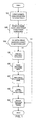
- FIG. 1 is a block diagram of an exemplary method.
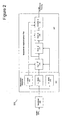
- FIG. 2 is an exemplary application framework of the individual modules of the invention.
- the invention is not limited to any particular software language described or implied in the figures. A variety of alternative software languages may be used for implementation of the invention. Some components and items are illustrated and described as if they were hardware elements, as is common practice within the art. However, various components in the method and system may be implemented in software or hardware.
- the invention is a modular framework and may be deployed as software as an application program tangibly embodied on a program storage device.
- the application code for execution can reside on a plurality of different types of computer readable media known to those skilled in the art.
- FIG. 1 shows an embodiment of a method for adapting the measurement suite configuration of a gas turbine engine to provide robust performance tracking in light of sensor failures or data dropouts.
- the method begins with acquiring engine gas path data samples at discrete times k (step 102).
- the gas path data comprises a plurality of gas path parameter measurements such as spool speeds, temperatures, pressures and flow rates.
- gas path parameter measurements such as spool speeds, temperatures, pressures and flow rates.
- the default set of parameters creates a measurement suite and is known a priori (step 103).
- a measurement matrix M c is assembled based on the default set of engine measurement parameters and is maintained.
- the vector of engine gas path parameters at a time k are typically compared to predefined thresholds in order to determine the quality and/or availability of the measurement parameters (step 104). An out-of-range parameter, or a missing parameter, would fail these tests and the vector of measurement parameters Z would be flagged as not having the default configuration. Likewise, if all of the parameters were within threshold, then the vector of measurement parameters would be flagged as having the default configuration and would immediately be available for performance diagnostic tracking (step 109).
- engine performance diagnostic tracking typically estimates sensor performance as well as engine module performance.
- the performance parameters usually take the form of changes, or performance deltas (from a nominal or installed state) in module efficiency and flow parameters.
- a sensor error parameter x is part of the gas path analysis and is estimated and tracked.
- Performance deltas are calculated from a reference (nominal). If all of the parameter deltas are close to zero and one parameter has a large delta value, it may indicate a "sensor" error. Sensor error is not limited to the instrument, but may include an error in the data recording, data reduction, normalization, etc .
- the sensor error is a measure of the accuracy of the sensor and is included in the performance estimation process to absorb the effects of sensor bias and drift and to a lesser degree, sensor nonrepeatability.
- Performance estimation helps in preventing corruption of the module performance estimates from sensor errors. Therefore, if a measurement parameter x is not present, any subsequent analysis should effectively drop the associated sensor error estimate from the performance estimation process.
- This process is controlled by a fault configuration matrix F c which is assembled and tracks the measurement configuration matrix M c .
- the fault configuration matrix F c is also an identity matrix. If M c is altered, F c will also be altered. A set of rules may be developed to control how F c is changed as a function of the change in M c , and may vary from application to application.
- a fault configuration matrix F c is assembled based on the default set of fault parameters and is maintained.
- the fault configuration matrix F c is an identity matrix of size n ( n ⁇ n ) where n is the number of performance faults being estimated x by the subsequent performance diagnostic tracking process and n>m.
- the fault configuration matrix F c includes the module estimated performance faults x (efficiency and flow parameter changes) as well as sensor faults and any other engine system fault that may be included in the performance diagnostic tracking process.
- the list of potential faults ( n ) to estimate for the default measurement configuration is predefined and specified by the analyst performing the diagnostic tracking.
- the fault configuration matrix F c is similarly updated (step 107).
- the fault configuration matrix F c is altered to exclude those faults whose estimation is affected by the loss of a corresponding measurement parameter(s) that is used to calculate the performance estimate (performed in step 106).
- the measurement configuration matrix M c is adjusted to reflect this. If the q th measured parameter is P25, M c ( q,q ) would be set to 0.
- the measurement configuration matrix M c and fault configuration matrix F c effectively removes the P25 measurement from the performance fault calculations and the P25 sensor error estimate from the active fault list by adaptation.
- Performance calculations are typically performed using a least squares, or generalized least squares estimation calculation.
- the Kalman filter is one approach that is used and is a generalized least squares approach that is used to teach the method.
- Performance tracking estimates are changes in various performance parameters such as efficiencies, flow capacities, sensor faults, etc., from perceived changes in the measured gas path parameters.
- the changes, or performance deltas, in the measured gas path parameters are calculated as percent changes from a reference that is typically the nominal engine values expected for the given flight and power condition.
- the percent deltas are calculated for each measured parameter m and stored as m ⁇ 1 vectors of percent deltas Z .
- the influence coefficient matrix H is typically partitioned into two submatrix sections, an engine performance fault submatrix H e and a sensor performance fault submatrix H s .
- H e is an m ⁇ n e submatrix and H s is an mxn s submatrix where n e represents the number of engine performance faults being tracked and n s is the number of measurement sensor faults being tracked where n e ⁇ n s and n s ⁇ m.
- (5) provides a means of calculating an estimate x ⁇ for the true (and unknown) vector of performance changes x.
- a -1 superscript indicates matrix inversion and a T superscript indicates matrix transposition.
- (5), (6), (7) and (8) represent Kalman filter equations.
- the measurement configuration M c and fault configuration F c matrices may be used to adapt the performance estimation process described above to fit the measurement configuration of the current data point being processed (step 109) as follows.
- FIG. 2 Shown in FIG. 2 is a framework 201 embodiment of the various modules that comprise and implement the invention.
- the framework 201 receives data from the monitoring sensors located on the gas turbine engine.
- the framework 201 comprises a data normalizer 203 coupled to a measurement adaptation module 205, which is coupled to an adaptive Kalman filter 207 for estimating gas turbine engine module performance changes.
- the data normalizer 203 compares acquired engine measurement data against an engine model to derive the engine performance measurement deltas.
- the measurement adaptation module 205 comprises a Z vector assembler 209, an F c matrix assembler 211 and an M c matrix assembler 213.
- the measurement deltas are assembled into a vector Z 209 and appropriate changes are made to the M c matrix 213, as previously described.
- the F c matrix assembler 211 modifies the performance faults that will be estimated from the current configuration of measurement deltas.
- the adaptive Kalman filter 207 comprises an adaptive influence H ⁇ matrix engine 215, an adaptive measurement covariance R ⁇ matrix engine 217, an adaptive Kalman gain D ⁇ matrix engine 219 and an adaptive state estimation x ⁇ engine 221.
- the measurement configuration M c 213 and fault configuration F c 211 matrices adapt the Kalman filter 207 to a given measurement suite. This process is performed at every time step k for which data is available for processing.
- the use of the configuration matrices M c and F c zero-out the appropriate rows and columns in the associated Kalman filter estimation process such that the remaining non-zero portions provide the same results one would obtain using the lower dimensional quantities dictated by the measurement suite.
- the measurement delta vector has essentially been reduced in size by one, to an ( m -1) ⁇ 1 vector. This reduction in dimensionality would normally require associated reductions in the model numerical elements, i.e. H, R, and D.
- the use of the M c and F c configuration matrices allow the original dimensions to be maintained. This supports an autonomous process that may reconfigure itself in accordance to the present measurement configuration without need for software changes or manual intervention.
Landscapes
- Physics & Mathematics (AREA)
- Engineering & Computer Science (AREA)
- General Physics & Mathematics (AREA)
- Automation & Control Theory (AREA)
- Artificial Intelligence (AREA)
- Evolutionary Computation (AREA)
- Mathematical Physics (AREA)
- Testing And Monitoring For Control Systems (AREA)
- Feedback Control In General (AREA)
Abstract
Description
- The invention relates generally to the field of gas turbine engine modeling. More specifically, the invention relates to methods and systems for adapting the measurement suite configuration of a gas turbine engine to provide robust performance tracking in light of sensor failures or data dropouts.
- Gas turbine performance diagnostics concerns itself with tracking changes in engine module performance measures (typically efficiency and flow parameters) as the engine deteriorates over time. The primary sources of information driving this methodology are measurements taking along the engine's gas path, such as temperatures, pressures, speeds, etc. Tracking fleets of engines across a wide customer/aircraft base offers the added complexity that the measured parameters differ in instrumentation and recording fidelity and non-repeatability across installations.
- Traditional performance diagnostic estimation methods employ some form of predictor/corrector estimation schemes. These procedures use the past performance estimation as a priori information for the current performance estimate calculation. Many of these approaches use linear estimation methods or derivatives of them to infer the performance changes from previous estimates and current data. The successful deployment of such diagnostic methods depends on many factors, one of which is its ability to adapt to different measurement suites without the need for employing complicated exception logic to cover all possible measurement scenarios.
- A provision to provide some form of measurement configuration that will adapt itself to the measurement suite currently available and adapt to changes in this measurement set over the life of the engine monitoring program without requiring changes in the diagnostic software is a step to providing needed robustness in the performance tracking process. There are several factors that drive the need for such a measurement configuration process.
- One factor is the fact that the number and types of gas path measurements available for conducting performance health trending, vary with the gas turbine model and type under consideration. For example, engines employing one or two spools, turbojet versus turbofan engines, mixed versus non-mixed flow, a new generation or a mature model engine, and others are factors that dictate what is and what is not available in the form of gas path instrumentation that provide the input parameter stream for the performance estimation process.
- Many methods known in the art for performing engine module performance health tracking are generic in the sense that they may be applied to any type of gas turbine. Engine model specifics are the numeric model constants and the measurement suite available for the application. The former is typically a database issue whereas the latter may affect the actual software implementation of the process. A process that adapts to any specific measurement configuration would provide a greater degree of robustness and negate the need for software changes to implement a specific measurement set.
- Another factor that drives the need for measurement configuration is that data dropouts are commonplace in aircraft engine monitoring. Parameters may, for whatever reason, disappear from the recorded input stream either intermittently for periods of time, or altogether. This may occur because of instrumentation problems, maintenance actions, recording anomalies, etc. Whatever the cause, the effective measurement suite changes as a result. If the performance estimation processing is dependent on a (pre-selected) measurement suite, the intermittent (or persistent) loss of one or more input parameters will cause a gap in the analysis to occur.
- What is needed is a more robust engine performance tracking process that identifies the current time point measurement suite and adapts the measurement suite to changes to allow the performance estimation process to proceed.
- Although there are various methods and systems that perform engine performance tracking, such methods and systems are not completely satisfactory. The inventor has discovered that it would be desirable to have methods and systems that adapt the measurement suite configuration of a gas turbine engine to provide robust performance tracking in light of sensor failures or data dropouts.
- One aspect of the invention provides a method for adapting measurements from a gas turbine engine for use in performance tracking. Methods according to this aspect of the invention preferably start with selecting a default engine configuration for the gas turbine engine and its application, acquiring gas path data samples corresponding to a predetermined number of measured parameters, deriving performance parameters for the gas turbine engine, comparing the measured parameters and performance parameters at time k with predefined thresholds to determine the quality and/or availability of each parameter, wherein parameters determined to be questionable are defined as not present for performance tracking, determining a measurement configuration matrix Mc based on the default engine configuration and present measured parameters Z, and a fault configuration matrix Fc based on the default engine configuration and present performance parameters x, and adapting performance tracking methods using the measurement configuration matrix Mc and fault configuration matrix Fc.
- Another aspect of the method is where the measurement configuration matrix Mc is an identity matrix of size m where m = number of measured parameters.
- Another aspect of the method is where the fault configuration matrix Fc is an identity matrix of size n where n = the number of performance faults being estimated.
- Another aspect of the method is where a zero entry in the measurement configuration matrix Mc main diagonal represents a questionable or missing parameter measurement.
- Another aspect of the method is where a zero entry in the fault configuration matrix Fc main diagonal represents those faults whose estimation is affected by the loss of a corresponding measurement parameter(s) that is used to calculate the performance estimate.
- The details of one or more embodiments of the invention are set forth in the accompanying drawings and the description below. Other features and advantages of the invention will be apparent from the description and drawings, and from the claims.
-
FIG. 1 is a block diagram of an exemplary method. -
FIG. 2 is an exemplary application framework of the individual modules of the invention. - Embodiments of the invention will be described with reference to the accompanying drawing figures wherein like numbers represent like elements throughout. Further, it is to be understood that the phraseology and terminology used herein is for the purpose of description and should not be regarded as limiting. The use of "including," "comprising," or "having" and variations thereof herein is meant to encompass the items listed thereafter and equivalents thereof as well as additional items. The terms "mounted," "connected," and "coupled" are used broadly and encompass both direct and indirect mounting, connecting, and coupling. Further, "connected" and "coupled" are not restricted to physical or mechanical connections or couplings.
- The invention is not limited to any particular software language described or implied in the figures. A variety of alternative software languages may be used for implementation of the invention. Some components and items are illustrated and described as if they were hardware elements, as is common practice within the art. However, various components in the method and system may be implemented in software or hardware.
- The invention is a modular framework and may be deployed as software as an application program tangibly embodied on a program storage device. The application code for execution can reside on a plurality of different types of computer readable media known to those skilled in the art.
-
FIG. 1 shows an embodiment of a method for adapting the measurement suite configuration of a gas turbine engine to provide robust performance tracking in light of sensor failures or data dropouts. The method begins with acquiring engine gas path data samples at discrete times k (step 102). The gas path data comprises a plurality of gas path parameter measurements such as spool speeds, temperatures, pressures and flow rates. For a particular gas turbine engine model and its particular application, there may be a default set of parameters measured in the engine's gas path. This conforms to a standard "bill-of-material" sensor configuration for that engine model and application. - The default set of parameters creates a measurement suite and is known a priori (step 103). A measurement matrix Mc is assembled based on the default set of engine measurement parameters and is maintained. The measurement matrix Mc is an identity matrix of size m (mxm) where m is the number of measured parameters and is defined by

where i and j are row and column indices. - The vector of engine gas path parameters at a time k are typically compared to predefined thresholds in order to determine the quality and/or availability of the measurement parameters (step 104). An out-of-range parameter, or a missing parameter, would fail these tests and the vector of measurement parameters Z would be flagged as not having the default configuration. Likewise, if all of the parameters were within threshold, then the vector of measurement parameters would be flagged as having the default configuration and would immediately be available for performance diagnostic tracking (step 109).
- If the vector of measurement parameters Z was flagged as not having the default configuration indicating that at least one measurement parameter was either outside of the predefined threshold or was missing altogether, i.e. a data dropout. In either case, the questionable, or missing parameter measurement is determined not present for subsequent performance diagnostic tracking (step 105) and the measurement configuration matrix M c is altered (step 106)

- By way of background, engine performance diagnostic tracking typically estimates sensor performance as well as engine module performance. For the engine modules, the performance parameters usually take the form of changes, or performance deltas (from a nominal or installed state) in module efficiency and flow parameters. For the sensors themselves, a sensor error parameter x is part of the gas path analysis and is estimated and tracked.
- Performance deltas are calculated from a reference (nominal). If all of the parameter deltas are close to zero and one parameter has a large delta value, it may indicate a "sensor" error. Sensor error is not limited to the instrument, but may include an error in the data recording, data reduction, normalization, etc.
- The sensor error is a measure of the accuracy of the sensor and is included in the performance estimation process to absorb the effects of sensor bias and drift and to a lesser degree, sensor nonrepeatability. Performance estimation helps in preventing corruption of the module performance estimates from sensor errors. Therefore, if a measurement parameter x is not present, any subsequent analysis should effectively drop the associated sensor error estimate from the performance estimation process. This process is controlled by a fault configuration matrix Fc which is assembled and tracks the measurement configuration matrix Mc .
- When the measurement configuration matrix Mc is based on a default engine configuration, the fault configuration matrix Fc is also an identity matrix. If Mc is altered, F c will also be altered. A set of rules may be developed to control how Fc is changed as a function of the change in Mc, and may vary from application to application. A fault configuration matrix Fc is assembled based on the default set of fault parameters and is maintained. The fault configuration matrix Fc is an identity matrix of size n (n×n) where n is the number of performance faults being estimated x by the subsequent performance diagnostic tracking process and n>m. The fault configuration matrix Fc is defined by

- The fault configuration matrix Fc includes the module estimated performance faults x (efficiency and flow parameter changes) as well as sensor faults and any other engine system fault that may be included in the performance diagnostic tracking process. The list of potential faults (n) to estimate for the default measurement configuration is predefined and specified by the analyst performing the diagnostic tracking.
- If the measurement configuration matrix Mc has been updated (step 106) from the last time sample k-1, the fault configuration matrix Fc is similarly updated (step 107). The fault configuration matrix Fc is altered to exclude those faults whose estimation is affected by the loss of a corresponding measurement parameter(s) that is used to calculate the performance estimate (performed in step 106).
- For example, if the pressure measurement sensor coupled to the inlet of the High Pressure Compressor (HPC) (referred to as P25) failed, or if its output signal suffered a dropout, the measurement configuration matrix Mc is adjusted to reflect this. If the qth measured parameter is P25, Mc (q,q) would be set to 0. The fault configuration matrix Fc is similarly updated, Fc (p,p) = 0, where the pth parameter in the fault set represents the P25 sensor fault. In general, Fc is updated by

- In the performance tracking calculations that follow, the measurement configuration matrix Mc and fault configuration matrix F c effectively removes the P25 measurement from the performance fault calculations and the P25 sensor error estimate from the active fault list by adaptation. Performance calculations are typically performed using a least squares, or generalized least squares estimation calculation. The Kalman filter is one approach that is used and is a generalized least squares approach that is used to teach the method.
- Performance tracking estimates are changes in various performance parameters such as efficiencies, flow capacities, sensor faults, etc., from perceived changes in the measured gas path parameters. The changes, or performance deltas, in the measured gas path parameters are calculated as percent changes from a reference that is typically the nominal engine values expected for the given flight and power condition. The percent deltas are calculated for each measured parameter m and stored as m×1 vectors of percent deltas Z. The percent delta changes in the performance parameters n are computed as an nx1 vector x̂ as

where x0 is an n×1 vector of a priori estimations for the performance changes, D̃ is an nxm Kalman gain matrix, and H is an mxn set of influence coefficients in percent which represents the physics model for how measurement parameters change for 1% changes in the performance parameters. H represents a linear approximation model of the interrelationships between the performance parameter deltas x and the measured gas path parameter deltas Z. - The influence coefficient matrix H is typically partitioned into two submatrix sections, an engine performance fault submatrix He and a sensor performance fault submatrix H s. He is an m×ne submatrix and Hs is an mxns submatrix where ne represents the number of engine performance faults being tracked and ns is the number of measurement sensor faults being tracked where ne≠ ns and ns≥m. The total number of performance faults is n= ne+ns and H is the concatenation of the two submatrices, i.e.


where θ is an m×1 vector of random noise representing measurement nonrepeatability. (5) provides a means of calculating an estimate x̂ for the true (and unknown) vector of performance changes x. The Kalman gain matrix D is defined as
where R represents an mxm measurement covariance matrix and P 0 represents an nxn state covariance matrix. In the above equations, a -1 superscript indicates matrix inversion and a T superscript indicates matrix transposition. - The measurement covariance matrix R is calculated from knowledge of the known measurement sensor nonrepeatability standard deviations σi, i = 1,2,...,n s and the sensor performance fault influence coefficient submatrix Hs as

where S is an ns ×1 vector of the σi, i =1,2,...,ns values and diag(S) is an ns × ns diagonal matrix with S entries on the main diagonal and entries outside of the main diagonal are all zero. (5), (6), (7) and (8) represent Kalman filter equations. - Once the measurement configuration Mc and fault configuration Fc matrices have been updated (
steps 106, 107), they may be used to adapt the performance estimation process described above to fit the measurement configuration of the current data point being processed (step 109) as follows. - The measurement configuration Mc and fault configuration F c matrices adapt the influence coefficient matrix H, creating a modified influence coefficient matrix H̃

- The measurement configuration Mc in conjunction with the modified influence coefficient matrix H̃ adapt the measurement sensor nonrepeatability standard deviations S̃, creating a modified measurement covariance matrix R̃

where I. is an mxm identity matrix. - The modified influence coefficient matrix H̃ and modified measurement covariance matrix R̃ adapt the Kalman gain matrix D̃

- The performance delta x̂ is calculated using the modified values and is output

- The performance changes for x̂(i) where Fc (i,i)=1, and i=1,2,...,n, may be reported to the end-user for performance tracking purposes.
- Shown in
FIG. 2 is aframework 201 embodiment of the various modules that comprise and implement the invention. Theframework 201 receives data from the monitoring sensors located on the gas turbine engine. - The
framework 201 comprises adata normalizer 203 coupled to ameasurement adaptation module 205, which is coupled to anadaptive Kalman filter 207 for estimating gas turbine engine module performance changes. The data normalizer 203 compares acquired engine measurement data against an engine model to derive the engine performance measurement deltas. Themeasurement adaptation module 205 comprises aZ vector assembler 209, an Fc matrix assembler 211 and an Mc matrix assembler 213. The measurement deltas are assembled into avector Z 209 and appropriate changes are made to the Mc matrix 213, as previously described. The Fc matrix assembler 211 modifies the performance faults that will be estimated from the current configuration of measurement deltas. Theadaptive Kalman filter 207 comprises an adaptive influenceH̃ matrix engine 215, an adaptive measurement covarianceR̃ matrix engine 217, an adaptive Kalman gainD̃ matrix engine 219 and an adaptive state estimation x̂ engine 221. Themeasurement configuration M c 213 andfault configuration F c 211 matrices adapt theKalman filter 207 to a given measurement suite. This process is performed at every time step k for which data is available for processing. - The effect of updating the Kalman filter estimation equations as outlined above for a specific measurement configuration M c and associated fault configuration F c is to produce identically what would be tracked for performance changes given that measurement configuration suite from the onset. Since this process may be implemented in software or hardware, either on-board or off-board, the advantage in employing the invention is that there is no need for dynamic reallocation of memory to accommodate the changes in matrix sizes dictated by different measurement configurations. In the process described above, the matrix dimensions are fixed to the default measurement size m and performance fault size n and do not change.
- The use of the configuration matrices Mc and Fc zero-out the appropriate rows and columns in the associated Kalman filter estimation process such that the remaining non-zero portions provide the same results one would obtain using the lower dimensional quantities dictated by the measurement suite. In the previous example cited where the P25 pressure measurement drops out, the measurement delta vector has essentially been reduced in size by one, to an (m -1)×1 vector. This reduction in dimensionality would normally require associated reductions in the model numerical elements, i.e. H, R, and D. The use of the Mc and Fc configuration matrices allow the original dimensions to be maintained. This supports an autonomous process that may reconfigure itself in accordance to the present measurement configuration without need for software changes or manual intervention.
- One or more embodiments of the present invention have been described. Nevertheless, it will be understood that various modifications may be made without departing from the scope of the invention. Accordingly, other embodiments are within the scope of the following claims.
Claims (24)
- A method for adapting measurements from a gas turbine engine for use in performance tracking comprising:selecting a default engine configuration for the gas turbine engine and its application;acquiring gas path data samples corresponding to a predetermined number of measured parameters;deriving performance parameters for the gas turbine engine;comparing the measured parameters and performance parameters at time k with predefined thresholds to determine the quality and/or availability of each parameter, wherein parameters determined to be questionable are defined as not present for performance tracking;determining a measurement configuration matrix Mc based on the default engine configuration and present measured parameters Z, and a fault configuration matrix Fc based on the default engine configuration and present performance parameters x0; andadapting performance tracking methods using the measurement configuration matrix Mc and fault configuration matrix Fc .
- The method according to claim 1 wherein the measurement configuration matrix Mc is an identity matrix of size m where m = number of measured parameters .
- The method according to claim 2 wherein the fault configuration matrix Fc is an identity matrix of size n where n = the number of performance faults being estimated.
- The method according to claim 3 further comprising performing performance tracking calculations using a least squares or generalized least squares estimation calculation.
- The method according to claim 4 wherein the least squares estimation is a Kalman filter.
- The method according to claim 5 wherein the Kalman filter is an adaptive Kalman filter.
- The method according to claim 6 wherein a zero entry in the measurement configuration matrix Mc main diagonal represents a questionable or missing parameter measurement.
- The method according to claim 7 wherein a zero entry in the fault configuration matrix Fc main diagonal represents those faults whose estimation is affected by the loss of a corresponding measurement parameter(s) that is used to calculate the performance estimate.
- The method according to claim 8 further comprising adapting an influence coefficient matrix H using the measurement configuration Mc and fault configuration Fc matrices, creating a modified influence coefficient matrix H̃.
- The method according to claim 9 further comprising adapting a measurement sensor nonrepeatability standard deviation S using the measurement configuration Mc matrix and adapted influence coefficient matrix H̃, creating a modified measurement covariance matrix R̃.
- The method according to claim 10 further comprising adapting a Kalman gain matrix D̃ using the modified influence coefficient matrix H̃ and modified measurement covariance matrix R̃.
- The method according to claim 11 further comprising calculating a performance delta x̂ using the adapted Kalman gain matrix D̃, the adapted influence coefficient matrix H̃, present measured parameters Z, and present performance parameters x 0.
- A system for adapting measurements from a gas turbine engine for use in performance tracking comprising:means for selecting a default engine configuration for the gas turbine engine and its application;means for acquiring gas path data samples corresponding to a predetermined number of measured parameters;means for deriving performance parameters for the gas turbine engine;means for comparing the measured parameters and performance parameters at time k with predefined thresholds to determine the quality and/or availability of each parameter, wherein parameters determined to be questionable are defined as not present for performance tracking;means for determining a measurement configuration matrix Mc based on the default engine configuration and present measured parameters Z, and a fault configuration matrix Fc based on the default engine configuration and present performance parameters x ; andmeans for adapting performance tracking methods using the measurement configuration matrix Mc and fault configuration matrix Fc .
- The system according to claim 13 wherein the measurement configuration matrix Mc is an identity matrix of size m where m = number of measured parameters.
- The system according to claim 14 wherein the fault configuration matrix Fc is an identity matrix of size n where n = the number of performance faults being estimated.
- The system according to claim 15 further comprising means for performing performance tracking calculations using a least squares or generalized least squares estimation calculation.
- The system according to claim 16 wherein the least squares estimation is a Kalman filter.
- The system according to claim 17 wherein the Kalman filter is an adaptive Kalman filter.
- The system according to claim 18 wherein a zero entry in the measurement configuration matrix Mc main diagonal represents a questionable or missing parameter measurement.
- The system according to claim 19 wherein a zero entry in the fault configuration matrix Fc main diagonal represents those faults whose estimation is affected by the loss of a corresponding measurement parameter(s) that is used to calculate the performance estimate.
- The system according to claim 20 further comprising means for adapting an influence coefficient matrix H using the measurement configuration Mc and fault configuration Fc matrices, creating a modified influence coefficient matrix H̃.
- The system according to claim 21 further comprising means for adapting a measurement sensor nonrepeatability standard deviation S using the measurement configuration Mc matrix and adapted influence coefficient matrix H̃, creating a modified measurement covariance matrix R̃.
- The system according to claim 22 further comprising means for adapting a Kalman gain matrix D̃ using the modified influence coefficient matrix H̃ and modified measurement covariance matrix R̃.
- The system according to claim 23 further comprising means for calculating a performance delta x̂ using the adapted Kalman gain matrix D̃, the adapted influence coefficient matrix H̃, present measured parameters Z, and present performance parameters x 0.
Applications Claiming Priority (1)
| Application Number | Priority Date | Filing Date | Title |
|---|---|---|---|
| US11/657,323 US7441448B2 (en) | 2007-01-24 | 2007-01-24 | Process for adapting measurement suite configuration for gas turbine performance diagnostics |
Publications (3)
| Publication Number | Publication Date |
|---|---|
| EP1950634A2 true EP1950634A2 (en) | 2008-07-30 |
| EP1950634A3 EP1950634A3 (en) | 2008-12-17 |
| EP1950634B1 EP1950634B1 (en) | 2009-12-09 |
Family
ID=39454481
Family Applications (1)
| Application Number | Title | Priority Date | Filing Date |
|---|---|---|---|
| EP08250185A Ceased EP1950634B1 (en) | 2007-01-24 | 2008-01-15 | Process for adapting measurement suite configuration for gas turbine performance diagnostics |
Country Status (5)
| Country | Link |
|---|---|
| US (1) | US7441448B2 (en) |
| EP (1) | EP1950634B1 (en) |
| CN (1) | CN101231213A (en) |
| CA (1) | CA2617481C (en) |
| DE (1) | DE602008000344D1 (en) |
Cited By (1)
| Publication number | Priority date | Publication date | Assignee | Title |
|---|---|---|---|---|
| CN110672328A (en) * | 2019-11-05 | 2020-01-10 | 大连理工大学 | Turbofan engine health parameter estimation method based on random configuration network |
Families Citing this family (30)
| Publication number | Priority date | Publication date | Assignee | Title |
|---|---|---|---|---|
| US7860635B2 (en) * | 2006-05-12 | 2010-12-28 | The United States Of America As Represented By The Secretary Of The Army | Singular value decomposition-based method for optimal estimation of turbofan engine thrust and other unmeasurable parameters |
| US7826943B2 (en) * | 2007-04-02 | 2010-11-02 | General Electric Company | Method and system for diagnosing faults in a particular device within a fleet of devices |
| GB0712980D0 (en) * | 2007-07-04 | 2007-08-15 | Rolls Royce Plc | Engine performance model |
| US20090043447A1 (en) * | 2007-08-07 | 2009-02-12 | General Electric Company | Systems and Methods for Model-Based Sensor Fault Detection and Isolation |
| US8422402B2 (en) | 2008-04-01 | 2013-04-16 | International Business Machines Corporation | Broadcasting a message in a parallel computer |
| US8364340B2 (en) * | 2009-03-31 | 2013-01-29 | General Electric Company | Method and systems for virtual sensor selection and blending |
| US7881880B2 (en) * | 2009-04-01 | 2011-02-01 | United Technologies Corporation | Actuator performance monitoring system |
| US8437941B2 (en) | 2009-05-08 | 2013-05-07 | Gas Turbine Efficiency Sweden Ab | Automated tuning of gas turbine combustion systems |
| US9267443B2 (en) | 2009-05-08 | 2016-02-23 | Gas Turbine Efficiency Sweden Ab | Automated tuning of gas turbine combustion systems |
| US9671797B2 (en) | 2009-05-08 | 2017-06-06 | Gas Turbine Efficiency Sweden Ab | Optimization of gas turbine combustion systems low load performance on simple cycle and heat recovery steam generator applications |
| US9354618B2 (en) | 2009-05-08 | 2016-05-31 | Gas Turbine Efficiency Sweden Ab | Automated tuning of multiple fuel gas turbine combustion systems |
| US20110106680A1 (en) * | 2009-10-30 | 2011-05-05 | General Electric Company | Turbine operation degradation determination system and method |
| US8306791B2 (en) * | 2009-12-21 | 2012-11-06 | United Technologies Corporation | Method and system for modeling the performance of a gas turbine engine |
| US8862433B2 (en) * | 2010-05-18 | 2014-10-14 | United Technologies Corporation | Partitioning of turbomachine faults |
| US8949577B2 (en) | 2010-05-28 | 2015-02-03 | International Business Machines Corporation | Performing a deterministic reduction operation in a parallel computer |
| US8566841B2 (en) | 2010-11-10 | 2013-10-22 | International Business Machines Corporation | Processing communications events in parallel active messaging interface by awakening thread from wait state |
| US8751423B2 (en) | 2010-11-30 | 2014-06-10 | General Electric Company | Turbine performance diagnostic system and methods |
| RU2451278C1 (en) * | 2011-03-16 | 2012-05-20 | Открытое акционерное общество "Научно-производственное объединение "Сатурн" (ОАО "НПО "Сатурн") | Turbojet engine and method of its testing |
| US8738326B2 (en) | 2011-03-23 | 2014-05-27 | General Electric Company | Performance characteristic calculation and comparison |
| US8893083B2 (en) * | 2011-08-09 | 2014-11-18 | International Business Machines Coporation | Collective operation protocol selection in a parallel computer |
| US8910178B2 (en) | 2011-08-10 | 2014-12-09 | International Business Machines Corporation | Performing a global barrier operation in a parallel computer |
| US8423161B2 (en) * | 2011-08-24 | 2013-04-16 | General Electric Company | Methods and systems for gas turbine modeling using adaptive kalman filter |
| US9495135B2 (en) | 2012-02-09 | 2016-11-15 | International Business Machines Corporation | Developing collective operations for a parallel computer |
| AU2013245998B2 (en) * | 2012-04-10 | 2016-07-28 | Lockheed Martin Corporation | Efficient health management, diagnosis and prognosis of a machine |
| CN103117099B (en) * | 2013-01-23 | 2017-05-03 | 大连理工大学 | Realization Method of Nuclear Reactor Fault Diagnosis System Based on Filtering |
| EP2930633A1 (en) * | 2014-04-11 | 2015-10-14 | United Technologies Corporation | Portable memory device data modeling for effective processing for a gas turbine engine |
| AU2015247437B2 (en) | 2014-04-17 | 2018-12-20 | Lockheed Martin Corporation | Prognostics and health management system |
| CN105203327B (en) * | 2015-09-15 | 2019-05-21 | 中国航空工业集团公司沈阳发动机设计研究所 | A kind of gas circuit measurement parameter selection method applied to engine air passage analysis |
| CN108646710A (en) * | 2018-05-10 | 2018-10-12 | 中国民航大学 | A kind of electro-hydraulic joint steering engine method for estimating state based on improvement volume particle filter |
| CN110513242B (en) * | 2019-08-13 | 2020-10-16 | 中国水利水电科学研究院 | A method for diagnosing stability faults of hydropower stations with vibration frequency as the main clue |
Family Cites Families (14)
| Publication number | Priority date | Publication date | Assignee | Title |
|---|---|---|---|---|
| US4215412A (en) * | 1978-07-13 | 1980-07-29 | The Boeing Company | Real time performance monitoring of gas turbine engines |
| GB2211965B (en) * | 1987-10-31 | 1992-05-06 | Rolls Royce Plc | Data processing systems |
| US5447059A (en) * | 1993-12-27 | 1995-09-05 | Solar Turbines Incorporated | Apparatus and method for determining gas turbine engine life |
| GB2362481B (en) * | 2000-05-09 | 2004-12-01 | Rolls Royce Plc | Fault diagnosis |
| US6804612B2 (en) * | 2001-10-30 | 2004-10-12 | General Electric Company | Methods and systems for performing integrated analyzes, such as integrated analyzes for gas turbine power plants |
| US6760689B2 (en) * | 2002-01-04 | 2004-07-06 | General Electric Co. | System and method for processing data obtained from turbine operations |
| US7216071B2 (en) * | 2002-04-23 | 2007-05-08 | United Technologies Corporation | Hybrid gas turbine engine state variable model |
| US7233884B2 (en) * | 2002-10-31 | 2007-06-19 | United Technologies Corporation | Methodology for temporal fault event isolation and identification |
| US7136809B2 (en) * | 2002-10-31 | 2006-11-14 | United Technologies Corporation | Method for performing an empirical test for the presence of bi-modal data |
| US6909960B2 (en) * | 2002-10-31 | 2005-06-21 | United Technologies Corporation | Method for performing gas turbine performance diagnostics |
| US7031878B2 (en) * | 2002-12-16 | 2006-04-18 | General Electric Company | Systems and methods for diagnosing the cause of trend shifts in performance data |
| US6962043B2 (en) * | 2003-01-30 | 2005-11-08 | General Electric Company | Method and apparatus for monitoring the performance of a gas turbine system |
| US7415328B2 (en) * | 2004-10-04 | 2008-08-19 | United Technologies Corporation | Hybrid model based fault detection and isolation system |
| US8010320B2 (en) * | 2006-11-17 | 2011-08-30 | United Technologies Corporation | Reducing gas turbine performance tracking estimation non-repeatability |
-
2007
- 2007-01-24 US US11/657,323 patent/US7441448B2/en active Active
-
2008
- 2008-01-09 CA CA2617481A patent/CA2617481C/en not_active Expired - Fee Related
- 2008-01-15 DE DE602008000344T patent/DE602008000344D1/en active Active
- 2008-01-15 EP EP08250185A patent/EP1950634B1/en not_active Ceased
- 2008-01-22 CN CNA2008100051811A patent/CN101231213A/en active Pending
Cited By (1)
| Publication number | Priority date | Publication date | Assignee | Title |
|---|---|---|---|---|
| CN110672328A (en) * | 2019-11-05 | 2020-01-10 | 大连理工大学 | Turbofan engine health parameter estimation method based on random configuration network |
Also Published As
| Publication number | Publication date |
|---|---|
| CA2617481C (en) | 2011-01-04 |
| CN101231213A (en) | 2008-07-30 |
| EP1950634A3 (en) | 2008-12-17 |
| US20080177505A1 (en) | 2008-07-24 |
| CA2617481A1 (en) | 2008-07-24 |
| EP1950634B1 (en) | 2009-12-09 |
| US7441448B2 (en) | 2008-10-28 |
| DE602008000344D1 (en) | 2010-01-21 |
Similar Documents
| Publication | Publication Date | Title |
|---|---|---|
| EP1950634B1 (en) | Process for adapting measurement suite configuration for gas turbine performance diagnostics | |
| US7233884B2 (en) | Methodology for temporal fault event isolation and identification | |
| EP1418481B1 (en) | Method for performing gas turbine performance diagnostics | |
| EP1643332B1 (en) | Hybrid model based fault detection and isolation system | |
| US10338123B2 (en) | Fluid tank sensor network fault detection method | |
| US8311774B2 (en) | Robust distance measures for on-line monitoring | |
| EP1926001B1 (en) | Reducing gas turbine performance tracking estimation non-repeatability | |
| US6181975B1 (en) | Industrial process surveillance system | |
| US5586066A (en) | Surveillance of industrial processes with correlated parameters | |
| US11274607B2 (en) | Controlling a gas turbine considering a sensor failure | |
| Li et al. | Fault detection, identification and reconstruction of sensors in nuclear power plant with optimized PCA method | |
| EP3105644B1 (en) | Method of identifying anomalies | |
| US20040199362A1 (en) | Intelligent modelling of process and tool health | |
| JP7026012B2 (en) | Equipment status monitoring system and equipment status monitoring method | |
| Domański | Multifractal properties of process control variables | |
| CN113221096A (en) | Method and system for analyzing correlation of random events in chaotic engineering | |
| EP1927915B1 (en) | State initialization for gas turbine engine performance diagnogtics | |
| Léonard et al. | Adaptive estimation algorithm for aircraft engine performance monitoring | |
| US20240055304A1 (en) | Method and device for optimizing an amount of testing with respect to a total test time | |
| Zhou et al. | Overview of fault detection and identification for non-linear dynamic systems | |
| Babbar et al. | Fuzzy clustering based fault diagnosis for aircraft engine health management | |
| CN119043376A (en) | Self-calibration method and device for unmanned aerial vehicle MEMS sensor array | |
| Adgar et al. | Improving data reliability using statistical and artificial neural network strategies |
Legal Events
| Date | Code | Title | Description |
|---|---|---|---|
| PUAI | Public reference made under article 153(3) epc to a published international application that has entered the european phase |
Free format text: ORIGINAL CODE: 0009012 |
|
| AK | Designated contracting states |
Kind code of ref document: A2 Designated state(s): AT BE BG CH CY CZ DE DK EE ES FI FR GB GR HR HU IE IS IT LI LT LU LV MC MT NL NO PL PT RO SE SI SK TR |
|
| AX | Request for extension of the european patent |
Extension state: AL BA MK RS |
|
| PUAL | Search report despatched |
Free format text: ORIGINAL CODE: 0009013 |
|
| AK | Designated contracting states |
Kind code of ref document: A3 Designated state(s): AT BE BG CH CY CZ DE DK EE ES FI FR GB GR HR HU IE IS IT LI LT LU LV MC MT NL NO PL PT RO SE SI SK TR |
|
| AX | Request for extension of the european patent |
Extension state: AL BA MK RS |
|
| 17P | Request for examination filed |
Effective date: 20090225 |
|
| GRAP | Despatch of communication of intention to grant a patent |
Free format text: ORIGINAL CODE: EPIDOSNIGR1 |
|
| AKX | Designation fees paid |
Designated state(s): DE GB |
|
| GRAS | Grant fee paid |
Free format text: ORIGINAL CODE: EPIDOSNIGR3 |
|
| GRAA | (expected) grant |
Free format text: ORIGINAL CODE: 0009210 |
|
| AK | Designated contracting states |
Kind code of ref document: B1 Designated state(s): DE GB |
|
| REG | Reference to a national code |
Ref country code: GB Ref legal event code: FG4D |
|
| REF | Corresponds to: |
Ref document number: 602008000344 Country of ref document: DE Date of ref document: 20100121 Kind code of ref document: P |
|
| PLBE | No opposition filed within time limit |
Free format text: ORIGINAL CODE: 0009261 |
|
| STAA | Information on the status of an ep patent application or granted ep patent |
Free format text: STATUS: NO OPPOSITION FILED WITHIN TIME LIMIT |
|
| 26N | No opposition filed |
Effective date: 20100910 |
|
| REG | Reference to a national code |
Ref country code: DE Ref legal event code: R082 Ref document number: 602008000344 Country of ref document: DE Representative=s name: SCHMITT-NILSON SCHRAUD WAIBEL WOHLFROM PATENTA, DE |
|
| REG | Reference to a national code |
Ref country code: DE Ref legal event code: R082 Ref document number: 602008000344 Country of ref document: DE Representative=s name: SCHMITT-NILSON SCHRAUD WAIBEL WOHLFROM PATENTA, DE Ref country code: DE Ref legal event code: R081 Ref document number: 602008000344 Country of ref document: DE Owner name: UNITED TECHNOLOGIES CORP. (N.D.GES.D. STAATES , US Free format text: FORMER OWNER: UNITED TECHNOLOGIES CORPORATION, HARTFORD, CONN., US |
|
| REG | Reference to a national code |
Ref country code: DE Ref legal event code: R081 Ref document number: 602008000344 Country of ref document: DE Owner name: RAYTHEON TECHNOLOGIES CORPORATION (N.D.GES.D.S, US Free format text: FORMER OWNER: UNITED TECHNOLOGIES CORP. (N.D.GES.D. STAATES DELAWARE), FARMINGTON, CONN., US |
|
| P01 | Opt-out of the competence of the unified patent court (upc) registered |
Effective date: 20230519 |
|
| PGFP | Annual fee paid to national office [announced via postgrant information from national office to epo] |
Ref country code: GB Payment date: 20231219 Year of fee payment: 17 |
|
| PGFP | Annual fee paid to national office [announced via postgrant information from national office to epo] |
Ref country code: DE Payment date: 20231219 Year of fee payment: 17 |
|
| REG | Reference to a national code |
Ref country code: DE Ref legal event code: R119 Ref document number: 602008000344 Country of ref document: DE |
|
| GBPC | Gb: european patent ceased through non-payment of renewal fee |
Effective date: 20250115 |
|
| PG25 | Lapsed in a contracting state [announced via postgrant information from national office to epo] |
Ref country code: DE Free format text: LAPSE BECAUSE OF NON-PAYMENT OF DUE FEES Effective date: 20250801 |
|
| PG25 | Lapsed in a contracting state [announced via postgrant information from national office to epo] |
Ref country code: GB Free format text: LAPSE BECAUSE OF NON-PAYMENT OF DUE FEES Effective date: 20250115 |