EP1950498A1 - Oven - Google Patents
Oven Download PDFInfo
- Publication number
- EP1950498A1 EP1950498A1 EP07001358A EP07001358A EP1950498A1 EP 1950498 A1 EP1950498 A1 EP 1950498A1 EP 07001358 A EP07001358 A EP 07001358A EP 07001358 A EP07001358 A EP 07001358A EP 1950498 A1 EP1950498 A1 EP 1950498A1
- Authority
- EP
- European Patent Office
- Prior art keywords
- socket
- oven according
- plug
- till
- oven
- Prior art date
- Legal status (The legal status is an assumption and is not a legal conclusion. Google has not performed a legal analysis and makes no representation as to the accuracy of the status listed.)
- Granted
Links
- 238000007789 sealing Methods 0.000 claims abstract description 25
- 238000010411 cooking Methods 0.000 claims abstract description 8
- 229910000831 Steel Inorganic materials 0.000 claims description 7
- 229910001220 stainless steel Inorganic materials 0.000 claims description 7
- 239000010935 stainless steel Substances 0.000 claims description 7
- 239000010959 steel Substances 0.000 claims description 7
- 229910052710 silicon Inorganic materials 0.000 claims description 3
- 239000010703 silicon Substances 0.000 claims description 3
- 239000002184 metal Substances 0.000 claims description 2
- 238000000034 method Methods 0.000 claims description 2
- 239000003566 sealing material Substances 0.000 claims description 2
- 235000013305 food Nutrition 0.000 description 3
- 235000013372 meat Nutrition 0.000 description 2
- 238000005260 corrosion Methods 0.000 description 1
- 230000007797 corrosion Effects 0.000 description 1
- 230000007704 transition Effects 0.000 description 1
Images


Classifications
-
- F—MECHANICAL ENGINEERING; LIGHTING; HEATING; WEAPONS; BLASTING
- F24—HEATING; RANGES; VENTILATING
- F24C—DOMESTIC STOVES OR RANGES ; DETAILS OF DOMESTIC STOVES OR RANGES, OF GENERAL APPLICATION
- F24C7/00—Stoves or ranges heated by electric energy
- F24C7/08—Arrangement or mounting of control or safety devices
-
- H—ELECTRICITY
- H05—ELECTRIC TECHNIQUES NOT OTHERWISE PROVIDED FOR
- H05B—ELECTRIC HEATING; ELECTRIC LIGHT SOURCES NOT OTHERWISE PROVIDED FOR; CIRCUIT ARRANGEMENTS FOR ELECTRIC LIGHT SOURCES, IN GENERAL
- H05B6/00—Heating by electric, magnetic or electromagnetic fields
- H05B6/64—Heating using microwaves
- H05B6/6447—Method of operation or details of the microwave heating apparatus related to the use of detectors or sensors
Definitions
- the invention relates to an oven, especially to a domestic oven, with a cooking cavity, wherein a plug connection is arranged in a wall of the cavity for inserting a plug of a thermocouple, wherein the plug connection comprises a socket for receiving a part of the plug.
- thermocouple device is necessary to survey the temperature within the food, especially for the preparation of meat dishes. Here the centre temperature of the meat is of importance.
- ovens equipped with this option have to show also a steam function, i. e. steam is fed into the cavity for cooking a dish. It can also be necessary to combine the steam operation of the oven with a thermocouple device application.
- thermocouple device is problematic due to the following reasons: If the thermocouple device is not in use, i. e. if the plug of the thermocouple is not plugged in, a flap is arranged which seals the opening in the cavity wall, so that no steam can escape. If the plug of the thermocouple is inserted into the socket it has been found that it is possible that steam can escape through the small gap between the socket and the plug.
- thermocouple device So, it can occur that escaping steam corrodes the electrical contacts of the plug connection, as the steam can condensate at the electrical connection. So, a short-circuit can not be excluded. In the worst case a fire can occur. Therefore plug connections for the thermocouple device are sometimes not allowed due to safety requirements.
- thermocouple device for surveying the centre temperature of a dish to be prepared in the oven cavity. It should become possible to safely use the thermocouple without problems due to escaping steam.
- the solution of this object according to the invention is characterized in that the socket consists of or comprises a sealing element which surrounds at least an entry opening of the socket.
- the socket can be made from metal, wherein the sealing element is arranged at the entry opening of the socket.
- the socket is preferably made from stainless steel.
- the sealing element is beneficially attached to the socket by a vulcanising process.
- the plug can have a body part with a cylindrical section with a first diameter and a cylindrical connector element with a reduced diameter, wherein the connector element can intrude into the socket via the entry opening, wherein the axial end of the body part is designed to contact the seal element with a face side.
- the cylindrical connector element can have a groove at its axial end remote from the body part, wherein at least one elastic element is arranged for holding the cylindrical connector element in place by snapping or intruding into the groove.
- the plug connection can have a flap which is arranged pivotable at the plug connection around an axis.
- the axis can be arranged transversely to the longitudinal axis of the plug.
- the flap can be biased by a spring element.
- the flap is preferably free from sealing material, i. e. the sealing function is carried out by the above mentioned sealing element.
- the flap can be made from steel, especially from stainless steel.
- the axis of the flap can also be made from steel, especially from stainless steel.
- the sealing element consists of silicon.
- the sealing element can extend into a bore in the cavity wall to seal the socket into the bore. Thereby, no steam can escape between a gap between the bore in the wall and the socket.
- the socket can be designed as a two part design. Both parts of the socket can be connected by means of a screw connection.
- thermocouple microwaveprobe
- thermocouple An easy sealing becomes possible when the thermocouple is used or not without any actions required by the user of the oven.
- the logistics and the assembly for producing the oven is more simple as less parts are necessary to establish the desired function.
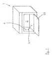
- FIG 1 shows a domestic oven 1. It has a cooking cavity 2'which can be opened by a door 22 (which is depicted in the opened state) to put food into the cavity 2 and to take cooked food out of it.
- the oven 1 is equipped with the possibility to survey the centre temperature of a dish which is prepared in the oven 1. Therefore, a wall 4 of the cavity has a bore in which a plug connection 3 is mounted. In FIG 1 an entry opening 9 of the plug connection 3 is shown without inserted thermocouple.
- the wall 4 of the cavity 2 has a bore 19 (see FIG 3 ) which is used to mount the plug connection 3.
- a socket 6 of the plug connection 3 is designed as a two-part arrangement, the parts being 20 and 21 (see FIG 3 ). Both parts 20, 21 can be connected by a screw connection.
- the socket 6 is prepared to receive a plug 5 or, more specifically, a part 7 of it.
- the received part is a cylindrical connector element 11 of the plug 5.
- the plug 5 has a body part 10 and the cylindrical connector part 11, wherein the diameter D of the body part 10 is bigger than the diameter d of the cylindrical part 11. So, a face side 12 is formed in the transition zone between the body part 10 and the cylindrical connector element 11.
- the socket 6 consists of or comprises a sealing element 8 which surrounds at least the entry opening 9 of the socket 6.
- the face side 12 of the body part 10 presses axially against the sealing element 8 when the plug 5 is inserted into the socket 6.
- the cylindrical connector element 11 has a groove 13 at its axial end in which an elastic element 14 snaps in in the mounted state.
- the sealing element 8 is vulcanized around a steel element, forming the part 20 of the socket 6. It extends into the region of the bore 19, so that the gap between the bore 19 and the socket 6 is also sealed by the sealing element 8.
- a flap 15 is arranged pivotably around an axis 16.
- the axis 16 is arranged transversely to the axis 17 of the plug 5.
- the flap 15 is made of non-corrosion steel and has no sealing element. It is biased by a spring element 18 which forces the flap 15 onto the opening 9 and consequently onto the sealing element 8.
- the bias force of the spring element 18 is selected in that way that enough pressure is exerted onto the flap 15 to safely close the opening 9 when the thermocouple is not in use.
- the invention suggests that the sealing element 8 is arranged at the fixed part of the socket 6, not on the flap 15.
- the seal is available and in use in both cases (thermocouple in use or not in use).
- the required parts - except from the sealing element 8 - can be made of stainless steel.
- the sealing element 8 can be made from high temperature resistant silicon.
- the sealing element 8 can be directly vulcanized on the steel part of the socket 6.
- the nut to fix the socket 6 at the cavity wall 4 is integrated in the fixed part of the cover.
Landscapes
- Engineering & Computer Science (AREA)
- Physics & Mathematics (AREA)
- Electromagnetism (AREA)
- Chemical & Material Sciences (AREA)
- Combustion & Propulsion (AREA)
- Mechanical Engineering (AREA)
- General Engineering & Computer Science (AREA)
- Electric Stoves And Ranges (AREA)
- Cookers (AREA)
- Measuring Temperature Or Quantity Of Heat (AREA)
Abstract
Description
- The invention relates to an oven, especially to a domestic oven, with a cooking cavity, wherein a plug connection is arranged in a wall of the cavity for inserting a plug of a thermocouple, wherein the plug connection comprises a socket for receiving a part of the plug.
- Ovens of this kind are well known in the art. For some applications a thermocouple device is necessary to survey the temperature within the food, especially for the preparation of meat dishes. Here the centre temperature of the meat is of importance. Sometimes ovens equipped with this option have to show also a steam function, i. e. steam is fed into the cavity for cooking a dish. It can also be necessary to combine the steam operation of the oven with a thermocouple device application.
- The use of a pluggable thermocouple device is problematic due to the following reasons: If the thermocouple device is not in use, i. e. if the plug of the thermocouple is not plugged in, a flap is arranged which seals the opening in the cavity wall, so that no steam can escape. If the plug of the thermocouple is inserted into the socket it has been found that it is possible that steam can escape through the small gap between the socket and the plug.
- So, it can occur that escaping steam corrodes the electrical contacts of the plug connection, as the steam can condensate at the electrical connection. So, a short-circuit can not be excluded. In the worst case a fire can occur. Therefore plug connections for the thermocouple device are sometimes not allowed due to safety requirements.
- Therefore, it is an object of the invention to improve a plug connection for the use of a thermocouple device for surveying the centre temperature of a dish to be prepared in the oven cavity. It should become possible to safely use the thermocouple without problems due to escaping steam.
- The solution of this object according to the invention is characterized in that the socket consists of or comprises a sealing element which surrounds at least an entry opening of the socket.
- The socket can be made from metal, wherein the sealing element is arranged at the entry opening of the socket. The socket is preferably made from stainless steel.
- The sealing element is beneficially attached to the socket by a vulcanising process.
- The plug can have a body part with a cylindrical section with a first diameter and a cylindrical connector element with a reduced diameter, wherein the connector element can intrude into the socket via the entry opening, wherein the axial end of the body part is designed to contact the seal element with a face side.
- The cylindrical connector element can have a groove at its axial end remote from the body part, wherein at least one elastic element is arranged for holding the cylindrical connector element in place by snapping or intruding into the groove.
- The plug connection can have a flap which is arranged pivotable at the plug connection around an axis. The axis can be arranged transversely to the longitudinal axis of the plug. The flap can be biased by a spring element. Furthermore, the flap is preferably free from sealing material, i. e. the sealing function is carried out by the above mentioned sealing element.
- The flap can be made from steel, especially from stainless steel. The axis of the flap can also be made from steel, especially from stainless steel.
- Preferably, the sealing element consists of silicon.
- The sealing element can extend into a bore in the cavity wall to seal the socket into the bore. Thereby, no steam can escape between a gap between the bore in the wall and the socket.
- The socket can be designed as a two part design. Both parts of the socket can be connected by means of a screw connection.
- The suggested design has the advantage, that the use of a thermocouple (meatprobe) can take place in a more secure way in a cooking function with low temperature steam as well as during normal cooking operation.
- An easy sealing becomes possible when the thermocouple is used or not without any actions required by the user of the oven.
- The logistics and the assembly for producing the oven is more simple as less parts are necessary to establish the desired function.
- In the drawings an embodiment of the invention is depicted.
- FIG 1
- shows schematically a perspective view of a domestic oven,
- FIG 2
- shows the cross sectional view through a plug connection with a plug inserted into the socket of the plug connection and
- FIG 3
- shows the same cross sectional view, wherein no plug is inserted into the socket of the plug connection.
-
FIG 1 shows a domestic oven 1. It has a cooking cavity 2'which can be opened by a door 22 (which is depicted in the opened state) to put food into thecavity 2 and to take cooked food out of it. The oven 1 is equipped with the possibility to survey the centre temperature of a dish which is prepared in the oven 1. Therefore, awall 4 of the cavity has a bore in which aplug connection 3 is mounted. InFIG 1 an entry opening 9 of theplug connection 3 is shown without inserted thermocouple. - Details of the proposed design become apparent from
figures 2 and3 where a cross sectional view is shown, inFIG 2 with insertedplug 5 of a thermocouple and inFIG 3 without the same. - In general, the
wall 4 of thecavity 2 has a bore 19 (seeFIG 3 ) which is used to mount theplug connection 3. Asocket 6 of theplug connection 3 is designed as a two-part arrangement, the parts being 20 and 21 (seeFIG 3 ). Bothparts 20, 21 can be connected by a screw connection. - The
socket 6 is prepared to receive aplug 5 or, more specifically, apart 7 of it. The received part is acylindrical connector element 11 of theplug 5. Theplug 5 has abody part 10 and thecylindrical connector part 11, wherein the diameter D of thebody part 10 is bigger than the diameter d of thecylindrical part 11. So, aface side 12 is formed in the transition zone between thebody part 10 and thecylindrical connector element 11. - An important feature of the present invention is that the
socket 6 consists of or comprises asealing element 8 which surrounds at least the entry opening 9 of thesocket 6. As can be seen infigure 2 , theface side 12 of thebody part 10 presses axially against the sealingelement 8 when theplug 5 is inserted into thesocket 6. To keep theplug 5 in position, thecylindrical connector element 11 has agroove 13 at its axial end in which anelastic element 14 snaps in in the mounted state. - The sealing
element 8 is vulcanized around a steel element, forming thepart 20 of thesocket 6. It extends into the region of thebore 19, so that the gap between thebore 19 and thesocket 6 is also sealed by the sealingelement 8. - To seal the
opening 9 when the thermocouple is not used, i. e. if theplug 5 is drawn out of thesocket 6, aflap 15 is arranged pivotably around anaxis 16. Theaxis 16 is arranged transversely to theaxis 17 of theplug 5. Theflap 15 is made of non-corrosion steel and has no sealing element. It is biased by aspring element 18 which forces theflap 15 onto the opening 9 and consequently onto the sealingelement 8. The bias force of thespring element 18 is selected in that way that enough pressure is exerted onto theflap 15 to safely close theopening 9 when the thermocouple is not in use. - Consequently, the
bore 19 and theentry opening 9 respectively are sealed in the case that aplug 5 is inserted into thesocket 6 and also in the case that noplug 5 is used. - So, the invention suggests that the sealing
element 8 is arranged at the fixed part of thesocket 6, not on theflap 15. Hereby, the seal is available and in use in both cases (thermocouple in use or not in use). - The required parts - except from the sealing element 8 - can be made of stainless steel. The sealing
element 8 can be made from high temperature resistant silicon. The sealingelement 8 can be directly vulcanized on the steel part of thesocket 6. As an additional function the nut to fix thesocket 6 at thecavity wall 4 is integrated in the fixed part of the cover. -
- 1
- Oven (domestic oven)
- 2
- Cooking cavity
- 3
- Plug connection
- 4
- Wall of the cavity
- 5
- Plug
- 6
- Socket
- 7
- Part of the plug
- 8
- Sealing element
- 9
- Entry opening
- 10
- Body part
- 11
- Cylindrical connector element
- 12
- Face side
- 13
- Groove
- 14
- Elastic element
- 15
- Flap
- 16
- Axis
- 17
- Axis of the plug
- 18
- Spring element
- 19
- Bore
- 20
- Part of the socket
- 21
- Part of the socket
- 22
- Door
- D
- First diameter
- d
- Reduced diameter
Claims (16)
- Oven (1), especially domestic oven, with a cooking cavity (2), wherein a plug connection (3) is arranged in a wall (4) of the cavity (2) for inserting a plug (5) of a thermocouple, wherein the plug connection (3) comprises a socket (6) for receiving a part (7) of the plug (5),
characterized in that
the socket (6) consists of or comprises a sealing element (8) which surrounds at least an entry opening (9) of the socket (6). - Oven according to claim 1, characterized in that the socket (6) is made from metal, wherein the sealing element (8) is arranged at the entry opening (9) of the socket (6).
- Oven according to claim 2, characterized in that the socket (6) is made from stainless steel.
- Oven according to claim 2 or 3, characterized in that the sealing element (8) is attached to the socket (6) by a vulcanising process.
- Oven according to at least one of claims 1 till 4, characterized in that the plug (5) has a body part (10) with a cylindrical section with a first diameter (D) and a cylindrical connector element (11) with a reduced diameter (d), wherein the connector element (11) can intrude into the socket (6) via the entry opening (9), wherein the axial end of the body part (10) is designed to contact the seal element (8) with a face side (12).
- Oven according to claim 5, characterized in that the cylindrical connector element (11) has a groove (13) at its axial end remote from the body part (10), wherein at least one elastic element (14) is arranged for holding the cylindrical connector element (11) in place by snapping or intruding into the groove (13).
- Oven according to at least one of claims 1 till 6, characterized in that the plug connection (3) has a flap (15) which is arranged pivotable at the plug connection (3) around an axis (16).
- Oven according to claim 7, characterized in that the axis (16) is arranged transversely to the longitudinal axis (17) of the plug (5).
- Oven according to claim 8, characterized in that the flap (15) is biases by a spring element (18).
- Oven according to at least one of claims 7 till 9, characterized in that the flap (15) is free from sealing material.
- Oven according to at least one of claims 7 till 10, characterized in that the flap (15) is made from steel, especially from stainless steel.
- Oven according to at least one of claims 7 till 11, characterized in that the axis (16) is made from steel, especially from stainless steel.
- Oven according to at least one of claims 1 till 12, characterized in that the sealing element (8) consists of silicon.
- Oven according to at least one of claims 1 till 13, characterized in that the sealing element (8) extends into a bore (19) or into a region of a bore (19) in the cavity wall (4) to seal the socket (6) in the bore (19).
- Oven according to at least one of claims 1 till 14, characterized in that the socket (6) has a two part design.
- Oven according to claim 15, characterized in that both parts (20, 21) of the socket (6) are connected by means of a screw connection.
Priority Applications (3)
| Application Number | Priority Date | Filing Date | Title |
|---|---|---|---|
| PL07001358T PL1950498T3 (en) | 2007-01-23 | 2007-01-23 | Oven |
| ES07001358T ES2531170T3 (en) | 2007-01-23 | 2007-01-23 | Oven |
| EP07001358.6A EP1950498B1 (en) | 2007-01-23 | 2007-01-23 | Oven |
Applications Claiming Priority (1)
| Application Number | Priority Date | Filing Date | Title |
|---|---|---|---|
| EP07001358.6A EP1950498B1 (en) | 2007-01-23 | 2007-01-23 | Oven |
Publications (2)
| Publication Number | Publication Date |
|---|---|
| EP1950498A1 true EP1950498A1 (en) | 2008-07-30 |
| EP1950498B1 EP1950498B1 (en) | 2014-12-03 |
Family
ID=38374165
Family Applications (1)
| Application Number | Title | Priority Date | Filing Date |
|---|---|---|---|
| EP07001358.6A Not-in-force EP1950498B1 (en) | 2007-01-23 | 2007-01-23 | Oven |
Country Status (3)
| Country | Link |
|---|---|
| EP (1) | EP1950498B1 (en) |
| ES (1) | ES2531170T3 (en) |
| PL (1) | PL1950498T3 (en) |
Cited By (3)
| Publication number | Priority date | Publication date | Assignee | Title |
|---|---|---|---|---|
| ITBO20080555A1 (en) * | 2008-09-12 | 2010-03-13 | Premark Feg Llc | DEVICE FOR DETECTION OF A GENERAL PARAMETER IN A OVEN, IN PARTICULAR, IN AN INDUSTRIAL OVEN |
| US20110186030A1 (en) * | 2007-03-29 | 2011-08-04 | Electrolux Home Products Corporation N.V. | Cooking oven and method for operating the same |
| DE102015205489A1 (en) | 2015-03-26 | 2016-09-29 | BSH Hausgeräte GmbH | household appliance |
Citations (4)
| Publication number | Priority date | Publication date | Assignee | Title |
|---|---|---|---|---|
| FR2723268A1 (en) * | 1994-07-28 | 1996-02-02 | Alcatel Cable Interface Sa | PROTECTED FEMALE CONNECTOR FOR COMMUNICATION NETWORK |
| EP1199528A2 (en) * | 2000-10-17 | 2002-04-24 | BSH Bosch und Siemens Hausgeräte GmbH | Socket for roast thermometer |
| EP1503147A1 (en) * | 2003-07-29 | 2005-02-02 | Electrolux Home Products Corporation N.V. | Device for sensing the temperature inside of an food item |
| EP1536182A1 (en) * | 2003-11-26 | 2005-06-01 | BSH Bosch und Siemens Hausgeräte GmbH | Socket for baking oven thermometer |
-
2007
- 2007-01-23 PL PL07001358T patent/PL1950498T3/en unknown
- 2007-01-23 ES ES07001358T patent/ES2531170T3/en active Active
- 2007-01-23 EP EP07001358.6A patent/EP1950498B1/en not_active Not-in-force
Patent Citations (4)
| Publication number | Priority date | Publication date | Assignee | Title |
|---|---|---|---|---|
| FR2723268A1 (en) * | 1994-07-28 | 1996-02-02 | Alcatel Cable Interface Sa | PROTECTED FEMALE CONNECTOR FOR COMMUNICATION NETWORK |
| EP1199528A2 (en) * | 2000-10-17 | 2002-04-24 | BSH Bosch und Siemens Hausgeräte GmbH | Socket for roast thermometer |
| EP1503147A1 (en) * | 2003-07-29 | 2005-02-02 | Electrolux Home Products Corporation N.V. | Device for sensing the temperature inside of an food item |
| EP1536182A1 (en) * | 2003-11-26 | 2005-06-01 | BSH Bosch und Siemens Hausgeräte GmbH | Socket for baking oven thermometer |
Cited By (3)
| Publication number | Priority date | Publication date | Assignee | Title |
|---|---|---|---|---|
| US20110186030A1 (en) * | 2007-03-29 | 2011-08-04 | Electrolux Home Products Corporation N.V. | Cooking oven and method for operating the same |
| ITBO20080555A1 (en) * | 2008-09-12 | 2010-03-13 | Premark Feg Llc | DEVICE FOR DETECTION OF A GENERAL PARAMETER IN A OVEN, IN PARTICULAR, IN AN INDUSTRIAL OVEN |
| DE102015205489A1 (en) | 2015-03-26 | 2016-09-29 | BSH Hausgeräte GmbH | household appliance |
Also Published As
| Publication number | Publication date |
|---|---|
| PL1950498T3 (en) | 2015-05-29 |
| EP1950498B1 (en) | 2014-12-03 |
| ES2531170T3 (en) | 2015-03-11 |
Similar Documents
| Publication | Publication Date | Title |
|---|---|---|
| US7018226B2 (en) | Electrical connector having a spring to facilitate mounting | |
| US10756470B2 (en) | Connecting element, household appliance having such a connecting element, and insert module | |
| US11848514B2 (en) | Elastomer seal spring | |
| KR101119736B1 (en) | Motor and compressor with the same | |
| KR101580746B1 (en) | Connector | |
| EP2486635B1 (en) | Gasket for electric cables | |
| EP1950498B1 (en) | Oven | |
| US9337567B2 (en) | Seal for an electric terminal | |
| US20100041257A1 (en) | Emi shielded electrical connector | |
| EP3528349B1 (en) | Electrical connector | |
| RU2398334C2 (en) | Heat resistant cable input | |
| CN109841996A (en) | The round plug-in connector of shielding | |
| US9048562B2 (en) | Contacting system for producing electrical contact between a cable and a sensor | |
| CN114199391B (en) | Sensor components | |
| EP2998653A1 (en) | Glow plug with pressure sensor | |
| WO2010105366A1 (en) | Cable termination apparatus and related methods | |
| US7642473B2 (en) | Explosion containment vessel | |
| CN217137481U (en) | Cooking utensil | |
| KR20210001671U (en) | Bellows pipe connecting structure | |
| JP4390427B2 (en) | Heater, glow plug and water heater | |
| KR102890394B1 (en) | Electric cooker | |
| CN118448211A (en) | Capillary tube mechanical protection structure | |
| CN109404963B (en) | Ignition device with unlocking ignition needle assembly | |
| CN210582148U (en) | Measuring structure of cooking utensil and cooking utensil with same | |
| EP3029441A1 (en) | A fitting for a measuring insert of a thermometer |
Legal Events
| Date | Code | Title | Description |
|---|---|---|---|
| PUAI | Public reference made under article 153(3) epc to a published international application that has entered the european phase |
Free format text: ORIGINAL CODE: 0009012 |
|
| 17P | Request for examination filed |
Effective date: 20070913 |
|
| AK | Designated contracting states |
Kind code of ref document: A1 Designated state(s): AT BE BG CH CY CZ DE DK EE ES FI FR GB GR HU IE IS IT LI LT LU LV MC NL PL PT RO SE SI SK TR |
|
| AX | Request for extension of the european patent |
Extension state: AL BA HR MK RS |
|
| AKX | Designation fees paid |
Designated state(s): AT BE BG CH CY CZ DE DK EE ES FI FR GB GR HU IE IS IT LI LT LU LV MC NL PL PT RO SE SI SK TR |
|
| RAP1 | Party data changed (applicant data changed or rights of an application transferred) |
Owner name: ELECTROLUX HOME PRODUCTS CORPORATION N.V. |
|
| RAP1 | Party data changed (applicant data changed or rights of an application transferred) |
Owner name: ELECTROLUX HOME PRODUCTS CORPORATION N.V. |
|
| GRAP | Despatch of communication of intention to grant a patent |
Free format text: ORIGINAL CODE: EPIDOSNIGR1 |
|
| INTG | Intention to grant announced |
Effective date: 20140924 |
|
| GRAS | Grant fee paid |
Free format text: ORIGINAL CODE: EPIDOSNIGR3 |
|
| GRAA | (expected) grant |
Free format text: ORIGINAL CODE: 0009210 |
|
| AK | Designated contracting states |
Kind code of ref document: B1 Designated state(s): AT BE BG CH CY CZ DE DK EE ES FI FR GB GR HU IE IS IT LI LT LU LV MC NL PL PT RO SE SI SK TR |
|
| REG | Reference to a national code |
Ref country code: GB Ref legal event code: FG4D |
|
| REG | Reference to a national code |
Ref country code: CH Ref legal event code: EP Ref country code: AT Ref legal event code: REF Ref document number: 699588 Country of ref document: AT Kind code of ref document: T Effective date: 20141215 |
|
| REG | Reference to a national code |
Ref country code: IE Ref legal event code: FG4D |
|
| REG | Reference to a national code |
Ref country code: DE Ref legal event code: R096 Ref document number: 602007039508 Country of ref document: DE Effective date: 20150115 |
|
| REG | Reference to a national code |
Ref country code: NL Ref legal event code: T3 |
|
| REG | Reference to a national code |
Ref country code: ES Ref legal event code: FG2A Ref document number: 2531170 Country of ref document: ES Kind code of ref document: T3 Effective date: 20150311 |
|
| REG | Reference to a national code |
Ref country code: AT Ref legal event code: MK05 Ref document number: 699588 Country of ref document: AT Kind code of ref document: T Effective date: 20141203 |
|
| PG25 | Lapsed in a contracting state [announced via postgrant information from national office to epo] |
Ref country code: FI Free format text: LAPSE BECAUSE OF FAILURE TO SUBMIT A TRANSLATION OF THE DESCRIPTION OR TO PAY THE FEE WITHIN THE PRESCRIBED TIME-LIMIT Effective date: 20141203 Ref country code: LT Free format text: LAPSE BECAUSE OF FAILURE TO SUBMIT A TRANSLATION OF THE DESCRIPTION OR TO PAY THE FEE WITHIN THE PRESCRIBED TIME-LIMIT Effective date: 20141203 |
|
| REG | Reference to a national code |
Ref country code: LT Ref legal event code: MG4D |
|
| PG25 | Lapsed in a contracting state [announced via postgrant information from national office to epo] |
Ref country code: LV Free format text: LAPSE BECAUSE OF FAILURE TO SUBMIT A TRANSLATION OF THE DESCRIPTION OR TO PAY THE FEE WITHIN THE PRESCRIBED TIME-LIMIT Effective date: 20141203 Ref country code: AT Free format text: LAPSE BECAUSE OF FAILURE TO SUBMIT A TRANSLATION OF THE DESCRIPTION OR TO PAY THE FEE WITHIN THE PRESCRIBED TIME-LIMIT Effective date: 20141203 Ref country code: GR Free format text: LAPSE BECAUSE OF FAILURE TO SUBMIT A TRANSLATION OF THE DESCRIPTION OR TO PAY THE FEE WITHIN THE PRESCRIBED TIME-LIMIT Effective date: 20150304 Ref country code: CY Free format text: LAPSE BECAUSE OF FAILURE TO SUBMIT A TRANSLATION OF THE DESCRIPTION OR TO PAY THE FEE WITHIN THE PRESCRIBED TIME-LIMIT Effective date: 20141203 Ref country code: SE Free format text: LAPSE BECAUSE OF FAILURE TO SUBMIT A TRANSLATION OF THE DESCRIPTION OR TO PAY THE FEE WITHIN THE PRESCRIBED TIME-LIMIT Effective date: 20141203 |
|
| REG | Reference to a national code |
Ref country code: PL Ref legal event code: T3 |
|
| PG25 | Lapsed in a contracting state [announced via postgrant information from national office to epo] |
Ref country code: EE Free format text: LAPSE BECAUSE OF FAILURE TO SUBMIT A TRANSLATION OF THE DESCRIPTION OR TO PAY THE FEE WITHIN THE PRESCRIBED TIME-LIMIT Effective date: 20141203 Ref country code: PT Free format text: LAPSE BECAUSE OF FAILURE TO SUBMIT A TRANSLATION OF THE DESCRIPTION OR TO PAY THE FEE WITHIN THE PRESCRIBED TIME-LIMIT Effective date: 20150403 Ref country code: RO Free format text: LAPSE BECAUSE OF FAILURE TO SUBMIT A TRANSLATION OF THE DESCRIPTION OR TO PAY THE FEE WITHIN THE PRESCRIBED TIME-LIMIT Effective date: 20141203 Ref country code: CZ Free format text: LAPSE BECAUSE OF FAILURE TO SUBMIT A TRANSLATION OF THE DESCRIPTION OR TO PAY THE FEE WITHIN THE PRESCRIBED TIME-LIMIT Effective date: 20141203 Ref country code: SK Free format text: LAPSE BECAUSE OF FAILURE TO SUBMIT A TRANSLATION OF THE DESCRIPTION OR TO PAY THE FEE WITHIN THE PRESCRIBED TIME-LIMIT Effective date: 20141203 |
|
| PG25 | Lapsed in a contracting state [announced via postgrant information from national office to epo] |
Ref country code: LU Free format text: LAPSE BECAUSE OF FAILURE TO SUBMIT A TRANSLATION OF THE DESCRIPTION OR TO PAY THE FEE WITHIN THE PRESCRIBED TIME-LIMIT Effective date: 20150123 Ref country code: IS Free format text: LAPSE BECAUSE OF FAILURE TO SUBMIT A TRANSLATION OF THE DESCRIPTION OR TO PAY THE FEE WITHIN THE PRESCRIBED TIME-LIMIT Effective date: 20150403 |
|
| REG | Reference to a national code |
Ref country code: DE Ref legal event code: R097 Ref document number: 602007039508 Country of ref document: DE |
|
| PG25 | Lapsed in a contracting state [announced via postgrant information from national office to epo] |
Ref country code: MC Free format text: LAPSE BECAUSE OF FAILURE TO SUBMIT A TRANSLATION OF THE DESCRIPTION OR TO PAY THE FEE WITHIN THE PRESCRIBED TIME-LIMIT Effective date: 20141203 |
|
| PLBE | No opposition filed within time limit |
Free format text: ORIGINAL CODE: 0009261 |
|
| STAA | Information on the status of an ep patent application or granted ep patent |
Free format text: STATUS: NO OPPOSITION FILED WITHIN TIME LIMIT |
|
| PG25 | Lapsed in a contracting state [announced via postgrant information from national office to epo] |
Ref country code: DK Free format text: LAPSE BECAUSE OF FAILURE TO SUBMIT A TRANSLATION OF THE DESCRIPTION OR TO PAY THE FEE WITHIN THE PRESCRIBED TIME-LIMIT Effective date: 20141203 |
|
| REG | Reference to a national code |
Ref country code: IE Ref legal event code: MM4A |
|
| 26N | No opposition filed |
Effective date: 20150904 |
|
| REG | Reference to a national code |
Ref country code: FR Ref legal event code: PLFP Year of fee payment: 10 |
|
| PG25 | Lapsed in a contracting state [announced via postgrant information from national office to epo] |
Ref country code: IE Free format text: LAPSE BECAUSE OF NON-PAYMENT OF DUE FEES Effective date: 20150123 |
|
| PG25 | Lapsed in a contracting state [announced via postgrant information from national office to epo] |
Ref country code: SI Free format text: LAPSE BECAUSE OF FAILURE TO SUBMIT A TRANSLATION OF THE DESCRIPTION OR TO PAY THE FEE WITHIN THE PRESCRIBED TIME-LIMIT Effective date: 20141203 |
|
| PG25 | Lapsed in a contracting state [announced via postgrant information from national office to epo] |
Ref country code: BE Free format text: LAPSE BECAUSE OF FAILURE TO SUBMIT A TRANSLATION OF THE DESCRIPTION OR TO PAY THE FEE WITHIN THE PRESCRIBED TIME-LIMIT Effective date: 20141203 |
|
| REG | Reference to a national code |
Ref country code: FR Ref legal event code: PLFP Year of fee payment: 11 |
|
| PG25 | Lapsed in a contracting state [announced via postgrant information from national office to epo] |
Ref country code: HU Free format text: LAPSE BECAUSE OF FAILURE TO SUBMIT A TRANSLATION OF THE DESCRIPTION OR TO PAY THE FEE WITHIN THE PRESCRIBED TIME-LIMIT; INVALID AB INITIO Effective date: 20070123 Ref country code: BG Free format text: LAPSE BECAUSE OF FAILURE TO SUBMIT A TRANSLATION OF THE DESCRIPTION OR TO PAY THE FEE WITHIN THE PRESCRIBED TIME-LIMIT Effective date: 20141203 |
|
| REG | Reference to a national code |
Ref country code: FR Ref legal event code: PLFP Year of fee payment: 12 |
|
| PGFP | Annual fee paid to national office [announced via postgrant information from national office to epo] |
Ref country code: PL Payment date: 20191227 Year of fee payment: 14 |
|
| PGFP | Annual fee paid to national office [announced via postgrant information from national office to epo] |
Ref country code: NL Payment date: 20200121 Year of fee payment: 14 |
|
| PGFP | Annual fee paid to national office [announced via postgrant information from national office to epo] |
Ref country code: CH Payment date: 20200121 Year of fee payment: 14 |
|
| PGFP | Annual fee paid to national office [announced via postgrant information from national office to epo] |
Ref country code: TR Payment date: 20200122 Year of fee payment: 14 |
|
| REG | Reference to a national code |
Ref country code: CH Ref legal event code: PL |
|
| REG | Reference to a national code |
Ref country code: NL Ref legal event code: MM Effective date: 20210201 |
|
| PG25 | Lapsed in a contracting state [announced via postgrant information from national office to epo] |
Ref country code: NL Free format text: LAPSE BECAUSE OF NON-PAYMENT OF DUE FEES Effective date: 20210201 |
|
| PG25 | Lapsed in a contracting state [announced via postgrant information from national office to epo] |
Ref country code: LI Free format text: LAPSE BECAUSE OF NON-PAYMENT OF DUE FEES Effective date: 20210131 Ref country code: CH Free format text: LAPSE BECAUSE OF NON-PAYMENT OF DUE FEES Effective date: 20210131 |
|
| PG25 | Lapsed in a contracting state [announced via postgrant information from national office to epo] |
Ref country code: PL Free format text: LAPSE BECAUSE OF NON-PAYMENT OF DUE FEES Effective date: 20210123 |
|
| PGFP | Annual fee paid to national office [announced via postgrant information from national office to epo] |
Ref country code: FR Payment date: 20230124 Year of fee payment: 17 Ref country code: ES Payment date: 20230224 Year of fee payment: 17 |
|
| PGFP | Annual fee paid to national office [announced via postgrant information from national office to epo] |
Ref country code: IT Payment date: 20230120 Year of fee payment: 17 Ref country code: GB Payment date: 20230124 Year of fee payment: 17 Ref country code: DE Payment date: 20230127 Year of fee payment: 17 |
|
| P01 | Opt-out of the competence of the unified patent court (upc) registered |
Effective date: 20230625 |
|
| REG | Reference to a national code |
Ref country code: DE Ref legal event code: R119 Ref document number: 602007039508 Country of ref document: DE |
|
| GBPC | Gb: european patent ceased through non-payment of renewal fee |
Effective date: 20240123 |
|
| PG25 | Lapsed in a contracting state [announced via postgrant information from national office to epo] |
Ref country code: TR Free format text: LAPSE BECAUSE OF NON-PAYMENT OF DUE FEES Effective date: 20210123 |
|
| PG25 | Lapsed in a contracting state [announced via postgrant information from national office to epo] |
Ref country code: DE Free format text: LAPSE BECAUSE OF NON-PAYMENT OF DUE FEES Effective date: 20240801 |
|
| PG25 | Lapsed in a contracting state [announced via postgrant information from national office to epo] |
Ref country code: GB Free format text: LAPSE BECAUSE OF NON-PAYMENT OF DUE FEES Effective date: 20240123 |
|
| PG25 | Lapsed in a contracting state [announced via postgrant information from national office to epo] |
Ref country code: FR Free format text: LAPSE BECAUSE OF NON-PAYMENT OF DUE FEES Effective date: 20240131 |
|
| PG25 | Lapsed in a contracting state [announced via postgrant information from national office to epo] |
Ref country code: GB Free format text: LAPSE BECAUSE OF NON-PAYMENT OF DUE FEES Effective date: 20240123 Ref country code: FR Free format text: LAPSE BECAUSE OF NON-PAYMENT OF DUE FEES Effective date: 20240131 Ref country code: DE Free format text: LAPSE BECAUSE OF NON-PAYMENT OF DUE FEES Effective date: 20240801 |
|
| PG25 | Lapsed in a contracting state [announced via postgrant information from national office to epo] |
Ref country code: IT Free format text: LAPSE BECAUSE OF NON-PAYMENT OF DUE FEES Effective date: 20240123 |
|
| REG | Reference to a national code |
Ref country code: ES Ref legal event code: FD2A Effective date: 20250228 |
|
| PG25 | Lapsed in a contracting state [announced via postgrant information from national office to epo] |
Ref country code: ES Free format text: LAPSE BECAUSE OF NON-PAYMENT OF DUE FEES Effective date: 20240124 |